cost -effectiveness of various frp repair ... -effectiveness of various frp repair techniques for rc...
TRANSCRIPT

COST -EFFECTIVENESS OF VARIOUS FRP REPAIR TECHNIQUES FOR RC STRUCTURES
T. Hassan 'Jhe Canadian Network of Centers of Excellence
ISIS Canada, University of Manitoba, Winnipeg, Manitoba, Canada R3T 5V6
S. Rizkalla North Carolina State University
Department of Civil Engineering Campus Box 7533, Raleigh, NC, USA 27695
KEYWORDS: CFRP, Strengthening, Slabs, Bridges, Concrete, Cost, Composite, Prestressed
ABSTRACT Advances in the fields of polymers and composites have resulted in a major development of high strength fibre reinforced polymers (FRP). These materials offer great potential for cost-effective retrofitting of concrete structures.
In response to the growing need for concrete repair and rehabilitation, an experimental program was conducted at the University of Manitoba in Winnipeg, Manitoba, Canada, to investigate the feasibility of using different strengthening techniques as well as different types of FRP in strengthening posttensioned bridge slabs. Half-scale models of a reinforced concrete bridge were constructed and tested to failure. The modeL with dimensions of 8.5 x 1.2 x 0.4 meters, consisted of one simple span and two overhanging cantilevers. Each specimen was tested at three different locations. The first and second tests were performed on the two cantilevers with the load applied at the edge of each cantilever, while the third test was conducted on the mid-span.
Five different strengthening techniques were investigated including near surface mounted Leadline bars, C-Bars, CFRP strips and externally bonded CFRP sheets and strips. Ultimate capacity, failure mechanism and cost analysis of various strengthening techniques for concrete bridges are presented.
INTRODUCTION In an aggressive environment, concrete may be vulnerable to chemical actions such as carbonation and chloride contamination which breaks down the alkaline barrier in the cement matrix. Consequently, the steel reinforcement in concrete structures becomes susceptible to rusting and corrosion Such a phenomena leads to further cracking and spalling of the concrete and even delamination of the concrete at the reinforcement level under more severe conditions. In the United States, nearly one third of the nation's 581,000 bridges were graded structurally deficient or functionally obsolete by the FHW A [Us DOT,I997]. A large number of these deficient bridges are reinforced or prestressed concrete structures, and are in urgent need of repair and strengthening. In the United Kingdom, over 10,000 concrete bridges need structural attention. In Europe, it is estimated that the repair of structures due to corrosion of rebars in reinforced concrete structures costs over $600 million annually [rann and Delpark, 1999].
A possible solution to combat reinforcement corrosion is the use of non-corrosive materials to replace conventional steel bars. High tensile strength, lightweight, adequate ductility and corrosion resistance characteristics make FRP ideal for such applications. FRP also provides cost effectiveness and a practical technique for the repair and strengthening of structures and bridges using externally bonded sheets or prefabricated laminates.
Manitoba Highways and Government Services is considering upgrading a concrete bridge constructed thirty years ago using near surface mounted FRP reinforcement The analysis conducted using current
43

codes indicated that the flexural strength of the bridge deck is not sufficient to withstand modem truck loads. To accommodate the HSS30 AASHTO truck design load, the analysis indicates a need of approximately 10 percent flexural strengthening of the existing bridge slab at the negative moment zone over the pier columns. Costs to demolish the existing structure, construct a replacement, and carry out required embankment and pavement modifications was estimated to exceed the two million dollar range. Costs will be lessened if the existing structure can be effectively rehabilitated.
Due to lack of information on the use of near surface mounted FRP reinforcement for flexural strengthening in regions of combined bending and high shear stresses, an experimental program has been undertaken to investigate the feasibility of using near surface mounted CFRP reinforcement to increase·the flexural capacity in the negative moment zones.
Three half-scale models of bridge No. 444 on Highways 101 and 59 in Winnipeg, Manitoba, Canada were cast and post-tensioned. The specimens were tested in simple span with double cantilever configuration. Each specimen was tested at three different locations. The first and second tests are performed on the two cantilevers with the load applied at the edge of each cantilever, while the third test was conducted on the mid-span. Prior to the third test on the mid-span, the cracks resulting from the first two tests were sealed entirely by injecting a high strength epoxy resin adhesive into the concrete to restore the slab to its original monolithic condition. The mid-span was then strengthened and tested The significance of this project is that strengthening is required to increase the flexural capacity at the location of the maximum shear stresses typically occurring at the maximum negative moment section of cantilevers and continuous beams.
The overall aim of the research is to gain experimental evidence and insight of the performance of various FRP strengthening techniques, recommend innovative and cost-effective methods, and provide complete design guidelines for use in retrofitting projects.
BRIDGE OU1LINE The bridge was constructed in the early 1970s. The bridge is designed for AASHTO HSS20 truck design load. The bridge is located at the intersection of Highways 101 and 59 in Winnipeg, Manitoba, Canada The bridge consists of four spans of 19.8 m, 29.0 m, 22.9 m, and 19.8 m as measured from west to east The thickness of the bridge slab is 800 mm, cast in place, partially voided, post-tensioned slab and supported by concrete pier columns and abutments as shown in Figure I.
west abutment bearing
west piers CL : t Criti,,' '~:t
,,::::::;::.~~ '4 \9.8 m .'. 290 m .'4 , , I i i Precast hollow .
east piers east abutment bearing ,
::::~ ! Cross sec lIon
22.9m , 19.8m ,
Modelled for testing
Figure 1. Schematic of bridge No. 444 in Winnipeg - Manitoba - Canada
44
lbe two main I • Upgrade tI
loads (HSS • Limit the c
TESTSPECIN To simulate tI supports of th transverse dire of the cantilev were selected . critical bendin~ (SAP2000). T computer soft developed by tt
The specimens steel bars on 1 actual mild !
reinforcement 4
and 250 mm c shown in Figure
r--l 611ltsN~~
·iiE 2001 F} = 1411
J 1 r----' ! 1 :----r--
L

) withstand modem truck (sis indicates a need of at the negative moment truct a replacement, and • exceed the two million ilitated.
:inforcement for flexural {peri mental program has
CFRP reinforcement to
nipeg, Manitoba, Canada with double cantilever
rst and second tests are anti lever, while the third the cracks resulting from resin adhesive into the
n was then strengthened to increase the flexural
t the maximum negative
t of the performance of Ie methods, and provide
AASHTO HSS20 truck , in Winnipeg, Manitoba, ~.8 m as measured from .Iy voided, post-tensioned
east abutment bearing ,
~ , i Cross section
19.8m , ., ,
;] ba- Canada
The twO main reasons for strengthening are: • Upgrade the section capacity in the negative moment zone above the piers to resist heavier truck
loads (HSS30) instead ofHSS20 AASHTO truck design load. • Limit the cracking under the increased service load level (HSS30).
TEST SPECIMENS To simulate the combined effect of high flexural and shear stresses occurring over the intermediate supports of the bridge, three half-scale models of the solid slab simulating the bridge deck in the transverse direction were constructed. In the specimen, the maximum negative moment at the support of the cantilever coincides with the point of maximum shear. The number and layout of the tendons were selected to have the same induced stress level of the bridge under service loading conditions. The critical bending moments for the bridge were evaluated based on a linear elastic finite element analysis (SAP2000) The loss of the prestressing force was predicted according to the CSA code using a computer software CONCISE (Computer Analysis and Design for Precast Prestressed Concrete) developed by the Canadian Prestressed Concrete Institute (CPCI).
The specimens were reinforced with four 15M mild steel bars on the top surface and five 15M mild steel bars on the bottom surface. The number of bars in the top surface was chosen to represent the actual mild steel reinforcement ratio in the cantilever portion of the existing bridge. Shear reinforcement consisted of U-shape stirrups spaced at 125 mm centre to centre in the cantilever span and 250 mm centre to centre in the simply supported span. Reinforcement details of the specimens are
shown in Figure 2.
r-l r-2 6!l:1S N~ 70mm No. 1O@125mm ~ No. 15
,.,
12-15 mm qiameter strands 5 No. 15 L-I L-2 I
1800 1450
1800 4900
8500
No.1O 250 mm
2450
Sec. Elevation
75
fr;::1 ~ :;::::;1· [;:=:;;-1[=;:· ] =;::-1 ::;tor ~~o ~70 ~ ill
1200 1200
6 !l:1S N~.10 !$ 70 mm
1800
1800
{(I-.-___ -9!1'iO.IO@125mm
Figure 2. Reinforcement details of test specimens
45

Bursting reinforcement was provided using six looped pairs of 10M bars spaced at 70 mm centre to centre. Twelve 15 mm 7-wire strands were used for post-tensioning the specimens.
STRENGTHENTINGPROCEDURES Slab S 1: To investigate the benefits of embedding CFRP bars in concrete grooves, one cantilever of specimen SI was strengthened using near surface mounted Leadline CFRP bars while the other cantilever remained unstrengthened. The Leadline bars are produced by Mitsubishi Chemicals Corporation, Japan. The bars have a modulus of elasticity of 147 GPa and an ultimate tensile strength of 1970 MPa Based on equilibrium and compatibility conditions, six 10 mm diameter Leadline COO bars were used to achieve a 30 percent increase in the ultimate load carrying capacity of the slab.
The location of the grooves was first marked using a chalk line. The grooves were 200 mm apart. A concrete saw was used to cut six grooves approximately 16 mm wide and 30 mm deep at the tension surface of the cantilever as shown in Figure 3. The groove ends were widened to provide wedge action and hence prevents any possible slip of the bars The bars were then placed in the grooves ensuring that they were completely covered with the epoxy as shown in Figure 4.
Figure 3. Cutting grooves for embedded Figure 4. CFRP bars inserted in epoxy CFRPbars
After completion of the first two tests on both cantilevers, the resulting cracks were injected. A i temporary seal [SCB Concresive 1446] was applied at the backside of the slab to prevent the injecting t adhesive from running out. Entry ports were placed at the cracked surfaces as shown in Figure 5. Two . metering pumps were used to drive the two components (resin and hardener) of a fast-setting epoxy adhesive [SCB Concresive 1360] to a special mixing head. The adhesive was mixed at the nozzle and injected through a special gasket, which prevented leakage on the face of the concrete. The adhesive was pumped into the first entry port until it began to show at the next adjacent port. The first injected port was then plugged and injection was resumed at the second port. This procedure was followed until all major cracks were filled as shown in Figure 6.
Figure 6. Injecting the cracks
46
Based on equihbriu used to achieve a grooves were 120 I
placing the bars were
Slab S2: The secol surface mounted ant near surface mount Teclmical Universit) existed between the failure. To compare (50 mm wide and 1 the cantilever slab. concrete substrate \\ and pre-cut prior to Finally, the strips w( roller.
The second cantilevf order to insert the s 25mm wide. Using i
the tension surface pro\ide the necessar placed in the groove 7b. The CFRP strip have a modulus of ela
Figure 7a. Filling the
After testing both ( further testing of thf pre\iously for specirr to centre were used slab. The same proce(
Slab S3: A v..idespTl onto the concrete 51
detruling problems a investigate the effect

mate tensile neter Leadline 'the slab.
~d in epoxy
(s were injected. A prevent the injecting NIl in Figure S. Two a fast-setting epoxy
ed at the nozzle and ncrete. The adhesive )rt. The first injected :edure was followed
cks
Based on equilibrium and compatibility conditions, ten 10 mrn diameter Leadline CFRP bars were used to achieve a 30 percent increase in the ultimate capacity of the simply supported slab. The grooves were 120 mm apart. The same procedures as described before for cutting the grooves and placing the bars were applied.
Slab S2: The second specimen was intended to investigate the potential application of both near surface mounted and externally bonded CFRP strips in repair of concrete bridges. The perfomlance of near surface mounted CFRP strips has been recently tested by Blaschko and Zilch, 1999 at the Technical University in Munich. Test results positively determined that a good and uniform bond existed between the strip and the concrete. The high tensile strength of the strip was fully utilized up to failure. To compare the behaviour of the second specimen with that of the first one, six CFRP strips (50 mm wide and 1.4 mm thick) were used to achieve a 30 percent increase in the ultimate capacity of the cantilever slab. The first cantilever was strengthened using externally bonded CFRP strips. The concrete substrate was prepared by grinding at the locations of the strips. The strips were measured and pre-cut prior to installation. The epoxy was then placed over the strips and on the concrete surface. Finally, the strips were placed on the concrete surface and gently pressed into the epoxy using a ribbed roller.
The second cantilever and the mid-span were strengthened with near surface mounted CFRP strips. In order to insert me strips wiiliin me concrete cover layer, me strips were cut into two halves each is 25mm wide. Using a concrete saw, grooves of approximately 5 mm wide and 25 mrn deep were cut at the tension surface of the specimens. The grooves were men injected with the epoxy adl1esive to provide me necessary bond with the surrounding concrete as shown in Figure 7a The strips were then placed in the grooves ensuring that they were completely covered with the epoxy as shown in Figure 7b. The CFRP strips are produced by S&P Clever Reinforcement Company, Switzerland. The strips have a modulus of elasticity of 150 GPa and an ultimate tensile strength of 2000 MPa
~
Figure 7a. Filling the grooves with epoxy Figure 7b. Inserting the CFRP strips inside grooves
After testing both cantilevers, the areas above the supports were substantially cracked To enable further testing of the mid-span, me cracks were injected following the same procedures as described previously for specimen S 1. 18 CFRP strips (25 mm wide and 1.4 mm thick) spaced by 66 mrn centre to centre were used to achieve a 30 percent increase in the ultimate capacity of the simply supported slab. The same procedures, in terms of cutting me grooves, placing the CFRP strips were applied.
Slab S3: A widespread memod for me rehabilitation of concrete structures is to bond CFRP sheets onto the concrete surface. This method can be seen as state-of-the-art technique in spite of some detailing problems and design aspects which could influence me failure modes. To experimentally investigate the effectiveness of this strengthening method compared to previous tested techniques, one
47

cantilever of specimen S3 as well as the simply supported span were strengthened using externally bonded CFRP sheets. The sheets are manufactured by Master Builders Technologies, Ltd., Ohio, USA. The required area of CFRP sheets was calculated to achieve a 30 percent increase in flexural capacity of the cantilever slab. For the first cantilever, the sheets were applied in two plies. The first ply covered the whole width of the specimen (1200 mm) willie the second ply covered 480 mm and was centred along the width of the specimen. Installation procedures are illustrated in Figure 8.
Figure 8. Installation procedures for CFRP sheets
The second cantilever was strengthened using eight near surface mounted C-BAR CFRP bars. The bars are manufactured by Marshall Industries Composites Inc., USA and characterized by its considerably low cost compared to Leadline bars used in specimen S1. The bars have a modulus of elasticity of III GPa and an ultimate tensile strength of 1918 MPa The bars were sandblasted first to enhance their bond with the epoxy adhesive. The bars were then inserted inside grooves cut at the top surface of the concrete
The simply supported span was strengthened with externally bonded CFRP sheets after injecting the cracks resulting from cantilever tests. The same technique used for specimens SI and S2 for the injection process was followed. Three plies of CFRP sheets were used to achieve a 30 percent increase in flexural capacity. The first two plies covered the whole width of the specimen, while the third ply covered 400 mm and was centred along the width of the specimen. Detailed information about the tested specimens is provided in Table 1. The designation of the tested specimens have the first letters either C, or SS refers to ~antilever or ~imply ~upported specimens, respectively.
Table 1. Details oftest specimens Slab No. Specimen Strengthening technique
1 C 1 Control specimen
2
3
C2 6 near surface mounted Leadline bars SS 1 10 near surface mounted Leadline bars
C3 C4 SS2
C5 C6 SS3
6 externally bonded CFRP strips (SOxl.4mm) 12 near surface mounted CFRP strips (2Sx1.4mm) 18 near surface mounted CFRP strips (2Sx1.4mm)
2 plies of CFRP sheets 8 near surface mounted C-BAR CFRP bars 3 plies of CFRP sheets
loop MTS SOOO kJ'I control mode with a beam and the slab to : For the cantilever te prevent possible dru provided as shown in
(I) Elaslomeric be. (2) Steel plale 20a:. (3) HSS 76X5QU (
(4) HSS IOOxI00x5
(5) Prestressed DY (6) IISS JOOxIOIl.d
l 750
J I )700 .. -.-! r- ------- ....
L ___ L7Il..L __ _
For the mid-span test: each end with the load
(I) Elaslomeric h
1- : . ' ..
1800
1800

strengthened using externally clmologies, Ltd., Ohio, USA. : increase in flexural capacity
in two plies. The first ply ly covered 480 mm and was in Figure 8.
~ C-BAR CFRP bars. The ~ and characterized by its [be bars have a modulus of lars were sandblasted first to inside grooves cut at the top
RP sheets after injecting the ~imens S 1 and S2 for the lchieve a 30 percent increase pecimen, while the third ply :tailed information about the ~imens have the first letters y,
m) L4mm) 1.4mm)
ine-Ioad acting on a width 10 design vehicle. A closed-
loop MrS 5000 kN (1.2 million pounds) testing machine was used to apply the load using stroke control mode with a rate of 0.5 mmlmin up to failure. Neoprene pads were placed between the steel beam and the slab to simulate the tires of the truck and to avoid local crushing of the concrete. For the cantilever tests, the load was applied at a distance of 325 mm from the cantilever edge. To prevent possible damage of the other cantilever during the frrst test, an intermediate support was provided as shown in Figure 9.
(1) Elastnmeric bearings (Xeaprene pads) -IOOx400x4 ----~ - --~'- -
(2) Steel plate 20Ox20 (Length~I200 mmj M T 5 (3) HSS 76X50X5 (Lenglh=J50mm)
(4) HSS IOOxI00x5 (Lenglh~I:J70mm) -----l~Jr--(5) Prestressed DYWIDAG bar (Diameter = J5.-Imm. PrestresJingjerce=178 k.\') .
(6) HSS ]OOX100X5 (Lenglh=J JOOmm)..Q) , Spreader beam ,-
't~1
I
" , . I ' ... ").'-
750 .'. I . ~ .. " ..J.'j .'
I 0
1700
1700
(6) , 800
Concrete blocks
5000
L-________________________ ~8~O. _____________________ __
Figure 9. Schematic of test set-up for cantilever tests
~
300
For the mid-span tests, the slab was simply supported with a 4.90 m span and a 1.80 m projection from each end with the load applied at the centre of the slab as shown in Figure 10.
- - ----r-l-- - --'/
/
.... , '. .- . -' -81 .' --.::.J r(l) (I)
8. 45 0
ooLr ;;;L
~ I
1800 2450 I
2450 ~ I
1800
1800 41 I 1800
8500
Figure 10 Schematic oftest set-up for simply supported tests
49

li{ I,'
TEST RESULTS AND DlSCUSION Cantilever Tests The load-deflection behaviour of cantilever specimens strengthened wi1h near swface mounted CFRP reinforcement C2, C4 and C6 are compared to the unstrengthened cantilever, CI, is shown in Figure 11.
700
600
500
400 U:lad (kN)
300
200
100
0
0 20 40 60 80 100 120 140 Cantilever deflection (rom)
Figure 11. Load-deflection behaviour of cantilever specimens strengthened with near swface mounted CFRP reinforcement
Identical behaviour was observed for all the specimens until cracking occurred at a load level of 180 kN for the unstrengthened cantilever and 190 kN for strengthened cantilevers. After cracking, a nonlinear behaviour was observed up to failure. The measured stitfuesses for the strengthened specimens are higher due to the addition of the CFRP reinforcement The presence of CFRP reinforcement precluded the flattening of the load-deflection curve, which was clear in the control specimen between 440 kN and 466 kN. Prior to yielding of the steel reinforcement, the stiffnesses of all strengthened cantilevers were almost the same and were 1.5 times higher than the stiffuess of the unstrengthened cantilever. The higher stiffuess of 1he strengthened cantilevers after cracking is attributed to the high elastic modulus of the CFRP reinforcement After yielding of the tension steel reinforcement at a load level of 440 kN, 1he stiffuess of 1he cantilever specimen strengthened with Leadline bars, specimen i C2, was three times higher than that of the unstreng1hened one. Using C-BAR CFRP bars instead of. Leadline bars increased 1he stiffuess by 20 percent However, using near swface mounted CFRP strips yielded a supreme stiffness increase by 35 percent. For the control specimen, the increase in the applied load was negligible after yielding of the steel reinforcement For strengthened cantilevers, the load resistance increased until the concrete was crushed in the compression zone. This is attributed to the linear stress-strain behaviour of the CFRP reinforcement up to failure.
Figure 12. shows the load-deflection behaviour of cantilever specimens, C3 and C5, strengthened with extemally bonded CFRP reinforcement. The behaviour of the control specimen was also shown for comparison. The figure indicates that the strength, stiffness and ductility are greatly improved with the addition of CFRP reinforcement. Identical behaviour was observed for specimens C3 and C5 until a load level of 500 kN. After yielding of the steel reinforcement, the stiffuess of specimen C5 was about 3.3 times higher than that of the unstrengthened cantilever.
50,
700
600
500
400
Load (kN) 300
200
o
Figure 12 \I
Initial cracking in the for specimen C3, as sm
Figure
Upon additional loadi delamination occurred of the steel reinforceml
The observed mode I
concrete at the face c of fail ure, the bottor bottom steel bars. Fie}!
CFRP-strengthened c specimen exhibited p load of the control !
Leadline bars increas Using C-BAR CFRP specimen strengthene percent, due to peeJir

r surface mounted CFRP , Cl, is shown in Figure
140
rengthened
red at a load level of 180 ,rs. After cracking, a nonhe strengthened specimens e of CFRP reinforcement control specimen between
fnesses of all strengthened [less of the unstrengthened g is attributed to the high
::Tl----------------------c-5,,-.-.---.. -.----.. ---~·---------,
~j Load (kN) 400 j
300
::j o 20
---------~\
/--~CI \
i
40 60 80 100 120 140
Cantilever deflection (mm)
Figure 12. Load-deflection behaviour of cantilever specimens strengthened with externally bonded CFRP reinforcement
Initial cracking in the concrete substrate .it the anchorage zone was observed at a load level of 400 kN for specimen C3, as shown in Figure lJ.
001 reinforcement at a load Figure 13. Initial cracking in the concrete substrate of specimen C3 at 400 kN h Leadline bars, specimen IAR CFRP bars instead of Upon additional loading the cracks continued to widen up to a load level of 530 kN where unstable rface mounted CFRP strips delamination occurred resulting in peeling of the strips. The load was then dropped to the yielding load ;i.men, the increase in the of the steel reinforcement until crushing of concrete occurred. trengthened cantilevers, the zone. This is attributed to The observed mode of failure for all cantilever specimens was crushing of the bottom surface of the
concrete at the face of the support, where maximum compressive stresses were induced. At the onset of failure, the bottom steel bars and the steel stirrups were exposed, followed by buckling of the
and CS, strengthened with, bottom steel bars. Flexural shear cracks were also observed before failure of the specimens. ;imen ~ also shown for I I greatly tmproved With thei CFRP-strengthened cantilever specimens showed considerable enhancement of strength. The control cimens C3 and CS until a, specimen exhibited plastic failure with concrete failing in compression and steel yielding. The failure of specimen CS was about load of the control specimen was 476 kN. Strengthening the specimen using near surface mounted
Leadline bars increased the strength by 36 percent in comparison to the design value of 30 percent. Using C-BAR CFRP bars instead of LeadIine bars enhanced the strength by 39 percent. The cantilever specimen strengthened with externally bonded CFRP strips showed a minor increase in strength by 11 percent, due to peeling of the strips from the concrete surface. Using the same anoount of CFRP strips
51

but inserted inside grooves increased the ultimate load carrying capacity by 43 percent. Furthermore, using externally bonded CFRP sheets yielded superior strength enhancement by 44 percent. Experimental results for cantilever specimens are summarized in TabJe 2. Typical faiJure due to crushing of concrete is shown in Figure 14.
Table 2. Experimental results of cantilever specimens Specimen Strengthening Cracking Deflection Ultimate Deflection
technique load (kN) at load (kN) at ultimate cracking (mm)
(mm) C1 N.A (Control) 180 9.1 476 92.5 C2 Near surface mounted 189 8.3 647 102
Leadline bars C3 Externally bonded CFRP 192 9.2 530' 39
strips C4 Near surface mounted 187 8.5 680 93
CFRP strips C5 Externally bonded CFRP 194 9.1 683 112
sheets , ' '~
C6 Near surface mounted C- 197 8.3 663 100 . 391 BAR
• Specimen C3 failed due to delamination of CFRP strips, followed by crushing of concrete • All other cantilever specimens failed due to crushing of concrete
Figure 14. Typical failure due to crushing of concrete for cantilever specimens
In general, strengthening using near surface mounted CFRP reinforcement decrease the crack width by a factor ranged between two and three. Comparable crack width was observed for specimens C3 and C5 Wltil separation of the CFRP strips took place at 500 kN, beyond which the crack width for specimens C3 increased significantly, with no increase in the applied load. This is attributed to the sudden transfer of tensile stresses carried by the CFRP strips to the steel reinforcement, which was already yielded. Such a phenomenon resulted in an enormous increase in the strains and consequently the crack width.
Simply Supported Tests The load-deflection behaviour of the simply supported specimens strengthened with CFRP reinforcement is shown in Figure 15. To investigate different strengthening techniques, it was decided not to test control specimen for the mid-span and to rely completely on the results obtained from nonlinear finite element analysis (Hassan et al., 2000)
52
"' ;~
I I
1200 [
1000
Un
(TOO -,:) 600
'" o .....l
400
o
Figun
The strengthened speci unstrengthened specimer of the CFRP reinforcem an increase in stifthess slabs were significant!) specimen. Identical beha 348 kN for the unstreng showed traditional nonyielding of the bottom same and were 1. 5 time showed comparable stiffi level of 660 kN, the sti unstrengthened slab. Us
, percent. Traditional flex observed for all three spec
The unstrengthened sial yielding at a load level ( surface mounted Leadlin, of 30 percent. Using ( Furthermore, using extel Experimental results of sil
ly by 43 percent. Furthermore, enhancement by 44 percent. ble 2. Typical failure due to
ting of concrete
ltilever specimens
ent decrease the crack width by observed for specimens C3 and lnd which the crack width for
load. This is attributed to the steel reinforcement, which was in the strains and consequently
ens strengthened with CFRP rung techniques, it was decided 1 the results obtained from 1100-
1200 .,------------------------,
lOOO
800 t --. l ~ i ......, , -0 600~ '" i o ...l
400
200
o
Unstrengthened mid-span (based on F.E. analysis)
~/~-;j ~V '""~ /r~m'
8500
10 20 30 40 50 60 70
Mid-span deflection (mm)
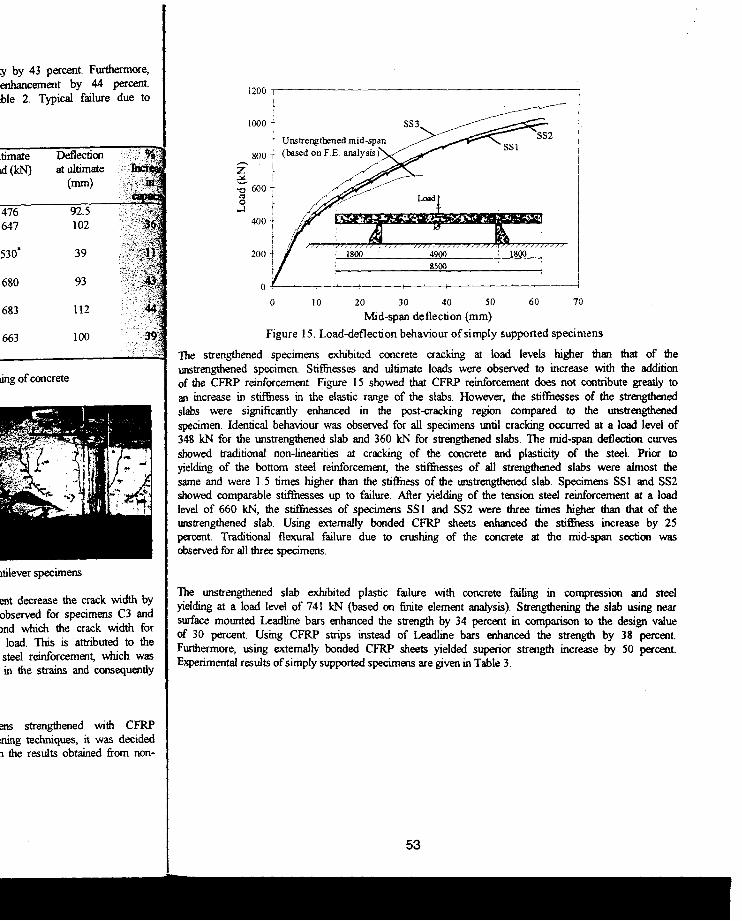
Figure 15. Load-deflection behaviour of simply supported specimens
The strengthened specimens exhibited concrete cracking at load levels higher than that of the unstrengthened specimen. Stiffnesses and ultimate loads were observed to increase with the addition of the CFRP reinforcement. Figure 15 showed that CFRP reinforcement does not contribute greatly to an increase in stiffness in the elastic range of the slabs. However, the stif'fuesses of the strengthened slabs were significantly enhanced in me post-cracking region compared to the unstrengthened specimen. Identical behaviour was observed for all specimens until cracking occurred at a load level of 348 kN for the unstrengthened slab and 360 kN for strengthened slabs. The mid-span deflection curves showed traditional non-Iinearities at cracking of the concrete and plasticity of the steel. Prior to yielding of the bottom steel reinforcement, the stiffnesses of all strengthened slabs were almost the same and were 1.5 times higher than the stiffness of the unstrengthened slab. Specimens SSI and SS2 showed comparable stif'fuesses up to failure. After yielding of the tension steel reinforcement at a load level of 660 kN, me stiffnesses of specimens S5 I and SS2 were t1vee times higher tI1an that of the unstrengthened slab. Using externally bonded CFRP sheets enhanced the stiffitess increase by 25 percent. Traditional flexural failure due to crushing of the concrete at the mid-span section was observed for all t1vee specimens.
The unstrengthened slab exhibited plastic failure wiili concrete failing in compression and steel yielding at a load level of 741 kN (based on finite element analysis). Strengthening the slab using near surface mounted Leadline bars enhanced me strength by 34 percent in compariSOfl to the design value of 30 percent. Using CFRP strips instead of Leadline bars enhanced ilie strength by 38 percent. Furtltermore, using externally bonded CFRP sheets yielded superior strength increase by 50 percent. Experimental results of simply supported specimens are given in Table 3.
53

Table 3. Experimental results of simply supported specimens
Specimen Strengthening Cracking Deflection Ultimate Deflection % technique load (kN) at load at ultimate Increase
cracking (kN) (mm) in (mm) capacity
SSl Near surface mOlmted 350 6.6 993 62.6 34' Leadline bars
SS2 Near surface momted 370 6.6 1022 62.0 38' CFRP strips
SS3 Externally bonded 362 6.8 IllS 67.2 50' CFRPsheets
'Ultimate load oflUlStrengthened specimen was based on non-linear F.E. analysis (Hassan et al,2000) - Failure of all specimens was due to crushing of the concrete
COST ANALYSIS
CONCLUSIONS Based on the findings of this i 1. The use of near St
strengthening/repair of co 2. Using externally bondec:
simply supported tests. 3. Strengthening using ext!
compared to 43 percent" 4. Strengthening using exte
strengthening in terms moment areas.
5. The crack width of u strengthened specimens.
6. Full composite action \\ strips) and the concrete ar
REFERENCES The prime objective of this study is to provide better understanding of the efficiency of each strengthening technique adopted. The efficiency needs to be defined in terms of strength enhancement I. and overall cost associated with it. The percentage increase in capacity, material cost, and overall cost
Blaschko, M., and Zild slits, Proc. of the J 2'h Int.
associated with each strengthening technique are shown in Figure 16.
60
50
40
Increase in capacity 30
(%)
20
10
o
I
• % Increase in capacity
• Conslruction costs in u.s. doU.",
Externally bonded CFRP strips
Near surface Mounted Leadline
bars
Near surface MOWlted C-BAR
bars
Near surface MOWlted
CFRP strips
Strengthening tedmique
200
160
120
80
40
o Externally bonded
CFRP sheets
Figure 16. Overall cost of various strengthening techniques
Cost in U.S. dollars
The figure indicates that using either near surface mounted CFRP strips or externally bonded CFRP i sheets yielded the maximum increase in strength. However, the overall cost of strengthening using' externally bonded CFRP sheets is only 2S percent of that using near surface mounted CFRP strips. Strengthening using either near surface mounted Leadline bars or C-BAR CFRP bars yielded approximately the same increase in ultimate load carrying capacity. With respect to cost, strengthening
. n L_~_ • _ J"''''' . " ,,--
2. Hassan, T., Horeczy, G.
3.
4.
Strengthening of Post-Te composite materials for 298. Tann, D. B. and Delpar~ narrow carbon strips, Pr< U.S. Department of Transportation Statistics.

ate Deflection % j at ultimate Increase ) (mrn) in
capacity 62.6 34"
2 62.0 3S·
5 67.2 50·
!lysis (Hassan et a1.,2000)
CONCLUSIONS Based on the findings of this investigation, the following conclusions can be drawn: 1. The use of near surface mounted CFRP reinforcement is feasible and effective for
strengthening/repair of concrete members especially in negative moment areas. 2. Using externally bonded CFRP sheets yielded superior strength increase for both cantilever and
simply supported tests. 3. Strengthening using externally bonded CFRP strips increased the ultimate capacity by II percent
compared to 43 percent when embedded inside the concrete. 4. Strengthening using externally bonded CFRP sheets has proven to be the most effective method of
strengthening in terms of strength, material cost and construction time especially in positive moment areas.
5. The crack width of unstrengthened specimens was two to three times larger than that of strengthened specimens.
6. Full composite action was observed between near surface mounted CFRP reinforcement (bars or strips) and the concrete and no slip was observed throughout the tests.
I1g of the efficiency of each REFERENCES terms of strength enhancement 1. Blaschko, M., and Zilch, K, (1999), Rehabilitation of concrete structures with strips glued into material cost, and overall cost slits, Proc. of the J jh Int. Con! on Composite Materials, Paris July 5th _9th, CD-Rom.
2. Hassan, T, Horeczy, G, Svecova, D., Rizkalla, S., Shehata, E., and Stewart, D., (2000) FleXliral Strengthening of Post-Tensioned Bridge Slab Using FRP, Proc. of the third Int. Con! on advanced
-----,- 200 composite materials for bridges and structures (ACMBS-Jl1), Ottawa, Ontario, July, 2000, 291-
160
120
Cost SO in U.S.
dollars
40
o :xtemally bonded
CFRP sheets
uques
JS or externally bonded CFRP ill cost of strengthening using surface mounted CFRP strips. C-BAR CFRP bars yielded
tt respect to cost, strengtherUng t strengthening using externally terms of strength improvement
29S. 3. Tann, D. B. and Delpark, R, (1999), Experimental Investigation of concrete beams reinforced with
narrow carbon strips, Proc. Int. Con! Structural Faults & Repair-99. CD-Rom 4. U.S. Department of Transportation (DOT), (1997), Bureau of Transportation Statistics,
Transportation Statistics Annual Report.
55