cost effective techniques for building construction …
TRANSCRIPT
l l / ' i j o r J l o b
COST EFFECTIVE TECHNIQUES FOR
BUILDING CONSTRUCTION
IN SRI LANKA by
W.D.R.P.Chitrangani
A thesis submitted to University of Moratuwa in partial fulfilment of the requirement for the degree of
Master of Structural Engineering Design
Research work supervised
by
Professor M.T.R.Jayasinghe and
Dr (Mrs) C. Jayasinghe
LIBRARY eiUIVERSITV OF MORATUWA, SRI LANKA
MORATUWA
DEPARTMENT OF CIVIL ENGINEERING UNIVERSITY OF MORATUWA
MORATUWA SRI LANKA
February 2006 l e . + . o U 6 * * )
University of Moratuwa
85383
85383

ABSTRACT
The cost of construction is gradually becoming a deterrent for large scale projects since a high capital cost will need higher returns from the facilities to make the investments viable. Therefore, there is an urgent need to control the cost of construction per square metre in order to make civil engineering projects financially more attractive. This can create more employment in the civil and building sectors for all segments involved. During the past decade, a large number of alternative building materials have been developed for the housing sector. Some of these include walling materials, alternative slab systems and roofing materials. Some of these can match the performance in both structural and durability terms while costing less. Some of these also allow reducing the amount of money spent for finishes and may have savings in formwork/falsework requirements. Most of these products are environmentally more acceptable. In this research, the structural concepts are developed for adopting the alternative building materials for reinforced concrete frame construction used in large engineering projects. Detailed designs and costing based on work studies have been used to evaluate the cost advantages offered by the use of these alternative materials. This thesis presents the details of this study in terms of structural performance, durability, savings in finishes and cost aspects which can make the alternative building products much more popular for large building projects.
In Sri Lanka cement stabilized soil block technology is used for single and two-storey construction. It is yet to penetrate to large building projects. Another alternative to brickwork is chip concrete blocks. These are initially introduced as hand moulded blocks, but now becoming popular with machine moulding. The main advantages are greater strength, lower shrinkage and lesser use of cement. The feasibility of using these materials as infill walls is investigated. Another advantage is the ability to avoid the plastering thus achieving further cost saving.
An alternative reinforced concrete precast slab system was introduced to the housing sector recently. The feasibility of using this in framed building is also investigated. Based on all these investigations, the design methodology, construction techniques and alternative finishes were presented. Detailed cost studies were carried out to determine the cost savings associated with different combinations of adopting above alternative materials. The cost savings were calculated as the basis of the actual costs and the associated project costs.
ii

Acknowledgement
I am grateful to the Vice Chancellor, Dean, Faculty of Engineering and Head of the Department of Civil Engineering for granting me an opportunity to follow the M. Eng. Degree on Structural Design. I wish to thank Dr. (Mrs.) M.T.P. Hettiarachchi for the encouragement given as the co-ordinator of research projects.
The staff members of Structural Engineering Division of Department of Civil Engineering who worked with much dedication during the lecture series are thanked with gratitude. The knowledge gained through lectures were of immense benefit to the research work presented in this thesis.
I am most grateful to my research supervisors Professor M.T.R.Jayasinghe and Dr Mrs. C. Jayasinghe of Department of Civil Engineering for their excellent support and encouragement given for the research work. A very special thank is due to them for their valuable advices and guidance from beginning till completion of this project.
1 am most grateful to Venerable Priest at Sri Sudarshana Bimbaramaya temple at Malamulla, Panadura for the excellent support and giving me an opportunity to visit the site at temple and employing his workers to cast machine moulded chip concrete blocks for my research work. Also I wish to thank the workers at the temple who helped me during that period with enthusiasm.
The staff of the Building Materials and Structural testing laboratories has helped me in many ways to make this research work a success. The excellent support given by them is acknowledged gratefully. Special thank is due for the technical officers Messers S.P.Madanayaka, S.L.Kapuruge and H.P.Nandaweera who took a special interest to carry out the laboratory work. Mr. G.V. Somaratna of computer laboratory also assisted with computer work.
Last, but not least, I wish to thank the staff of the Western Provincial Council who helped me in various ways to make this event a success.
I also wish to thank all those who have helped me to carry out this research work successfully.
iii

1
Contents
Abstract ii
Acknowledgement iii
Contents iv
* List of Figures xi
List of Tables xiii
Chapter 1: Introduction 1
1.1 General 1
1.2 Objectives 1
1.3 The methodology 2
1.4 Main findings 3
1.5 Arrangement of the thesis 4
Chapter 2: Literature review 5
2.1 General 5
2.2 Cement stabilised soil blocks 6
2.2.1 Stabilisation of soil 8
* 2.2.2 Physical identification of soils suitable for stabilisation . . . 8
2.2.3 Methods of stabilisation for soil blocks 10
2.2.4 Process of block making 11
2.2.5 Machines available for making compressed block 12
iv

2.2.5.1 Cinva ram machine
2.2.5.2 The Auram Press 3000
2.2.5.3 Modified Cinva ram Interlocking block press
2.2.6 Construction of structures with cement stabilised soil blocks
2.2.6.1 Foundations for cement stabilised soil block buildings
2.2.6.2 Plasters and coatings
2.2.7 Soil blocks with Aurum Press 3000
2.3 Hand moulded chip concrete blocks
2.3.1 Selection of mix proportions
2.3.2 Manufacturing of blocks
2.3.3 Compressive strength of hand moulded blocks
2.4 Concrete floor systems
2.4.1 Floor systems used in multi-storey buildings
2.4.1.1 One way slabs on beams and walls
2.4.1.2 Two-way slab on beams
2.4.1.3 One way pan joists and beams
2.4.1.4 One-way slab on beams and girders
2.4.1.5 Two way flat plate
2.4.1.6 Two way flat slab
2.4.1.7 Waffle flat slab
2.4.2 Alternative floor systems used for buildings in Sri Lanka
2.4.2.1 Precast prestressed concrete beam and insitu cast slab systems .

i 2.4.2.2 Precast prestressed concrete beam and slab systems with hollow blocks 28
2.4.2.3 Precast reinforced concrete beam and slab system 29
2.5 Summary 29
Chapter3 : Machine moulded chip concrete blocks 30
3.1 Introduction 30
3.2 Testing programme on machine moulded chip concrete blocks 30
3.2.1 Objectives of the research 30
3.2.2 The methodology carried out in the research programme ... 30
3.2.2.1 Selection of mix proportions 31
3.2.2.2 Manufacturing of Machine Moulded Chip Concrete Blocks ... 31
3.2.2.3 Testing of the Machine Moulded Chip Concrete Blocks for strength 31
3.2.2.4 Testing of the Machine Moulded Chip Concrete Blocks for shrinkage 31
3.3.1 The manufacturing of Machine Moulded Chip Concrete Blocks 31
* 3.3.2 Testing of Machine Moulded Chip Concrete Blocks for compressive 32 strength
3.3.2.1. Test results for compressing the Machine Moulded Chip Concrete 32 Blocks
3.3.2.2. Calculation of compressive strengths of the Machine Moulded Chip 32 Concrete Blocks
3.3.3 Shrinkage characteristics 33
3.3.3.1 Measuring Apparatus 33
3.3.3.2 Preparation of specimen 33
3.3.3.3 Measurement of drying shrinkage 34
3.3.3.4 Calculation of drying shrinkage of the MMCC Blocks 34
A
* 3.4 Summary 35
Chapter 4 : Precast reinforced concrete floor system 36
4.1 Introduction 36
4.2 Comparison between slab systems 36
4.3 The design study 37
4.3.1 Design of precast slab panels for construction and imposed loads 41
4.3.2 Design of precast beams for construction loads and imposed loads.. 42
4.3.3. Reinforcement details for precast slabs, beams and composite system.... 43
4.4 Adoption of alternative slabs for framed buildings 45
4.5 Summary 48
Chapter 5: Cost study 49
5.1 Introduction 49
5.2 The buildings used for case studies 49
5.3 Evaluation cost of individual items 51
5.3.1 Cost of machine moulded chip concrete blocks 51
5.3.1.1 Cost of cement 51
5.3.1.2 Cost of sand 52
5.2.1.3 Cost of chips 52
5.3.1.4 Cost of quarry dust 53
* 5.3.1.5 Cost of sand 53
5.2.1.6 Cost of machine usage 53
5.2.1.7 Cost of chip concrete blocks 53
5.3.1.8 Cost of 1:6 cement sand mortar for chip concrete blockwork 54
vii
A
5.3.1.8.1 Cost of mortar for 400mm x 100mm x 200 mm blocks
5.3.1.8.2 Cost of mortar for 151/2"x5"x71/2" blocks
5.3.1.9 Cost of labour for construction of chip concrete block walls
5.3.1.10 Total cost for construction of 1 m 2 area of chip concrete blockwork....
5.3.2 Cost of brick walls
5.3.2.1Cost of 210 mm thick brick walls
5.3.2.2 Cost of 110 mm thick brick walls
5.3.3 Cost of precast panels
5.3.3.1 Cost of concrete
5.3.3.2 Cost of reinforcement per panel
5.3.3.3 Cost of formwork
5.3.3.4 Cost of labour
5.3.3.5 Total cost per panel
5.3.4 Cost of precast beams
5.3.4.1 Cost of concrete
5.3.4.2 Cost of reinforcement per beam
5.3.4.3 Cost of formwork
5.3.4.4 Cost of labour
5.3.4.5 Total cost per beam
5.3.5 Cost of the composite slab
5.3.5.1 Cost of labour for the composite slab
5.3.5.2 Total cost of casting 1 m 2 of the composite slab
viii
T 5.4 The cost study 62
5.5 The results of the cost study 63
5.5.1 Cost of brick walls and MMCC block walls 63
5.5.1.1 Cost of 110mm. brick wall and 400 mm. x 100 mm. x 200 mm 63 MMCC block wall
5.5.1.2 Cost of 210mm. thick brickwall and 15 1/2"x5"x71/2" MMCC block 64 wall
5.5.2 Costs of buildings used for the case study 64
5.5.2.1 Total amount of Bill of Quantities and the Total Estimated Costs of 64 Buildingl
5.5.2.2 Total amount of Bill of Quantities and the Total Estimated Costs of 65 Building2
5.6 Analysis on cost study 65
5.6.1 Comparison of brick walls with MMCC block walls 65
5.6.1.1 Comparison of 110mm. thick brick wall with 400mm.xl00mm.x200m 65 4 MMCC block wall
5.6.1.2 Comparison of 210mm. thick brick wall with 151 /2"x5"x71 IT MMCC block 66 w a l l
5.6.2 Analysis of cost study for solid slab system and composite slab system 66
for Building 1 and Building 2
5.6.2.1 Comparison of overall costs of Building 1 and Building 2 67
5.6.2.2 Comparison of seven cases considered for Building 1 & Building 2... 68
5.7 Conclusions 69
5.7.1 Conclusions on machine moulded chip concrete blocks 69
5.7.2 Conclusions on precast reinforced concrete beam slab system 70
5.7.3 Conclusions on overall projects by adopting alternative building 71 materials
ix

5.8 Summary
Chapter 6: Conclusions and future work
6.1 General
6.2 Future works
References
Appendix
A Design of precast concrete reinforced concrete slab
Bl Bill of quantities for Building 1
B2 Summary sheet for Building 1
B3 Bill of quantities for Building 2
B4 Summary sheet for Building 1

Chapter 1
INTRODUCTION
1.1 General
The cost of buildings involving traditional materials and methods are becoming expensive which could become a deterrent for large-scale projects. This is because high capital cost will need higher returns from the facilities to make the investments viable. This is true for both government and private sector projects. Therefore, there is an urgent need to reduce the cost of construction per square meter in order to make civil engineering projects financially more attractive. If these alternative techniques could make a saving in the total quantity of materials, it could lead to reduced exploitation of natural resources thus giving additional benefits in environmental terms. Better financial viability also could create more projects and more employments in the civil and building sectors.
However, the alternative building material research and development has primarily concentrated on the housing sector where it would be easier to penetrate the industry. This is because the people facing financial constraints would be more receptive to alternative technology which could allow savings in the construction cost while providing acceptable level of finishes. In this thesis, the adoption of cement stabilised soil blocks, chip concrete blocks and precast beam slab systems for large buildings are presented. The extra savings that can be realized with some innovative approaches are also discussed.
1.2 The Objectives
The main objectives of the research work presented in this thesis is
to find suitable cost effective, environmentally friendly alternative building materials and systems that can be used for large buildings, which are as strong and durable as the conventional building materials
For the non-load bearing walls of buildings, cement stabilised soil blocks and machine moulded chip concrete blocks are introduced. For the floor slabs of multi-storey buildings, a more efficient and economical composite reinforced concrete precast slab system is introduced.
The alternative materials considered to fulfil the above objectives are the following:
1

Cement stabilised soil blocks
Laterite soil is found very close to the organic top soil in most parts of Sri Lanka. Laterite soil is an ideal material for stabilisation with cement. The stabilised soil can be used to make blocks using a suitable block-making machine. However, the use of these blocks as a building material for large buildings is yet to find wide acceptance due to inadequate use of available data on the strength and durability characteristics. In order to popularise this as a non load bearing material for large building construction, a study was carried out to identify the required strengths and durability of cement stabilised soil blocks.
Machine Moulded Chip Concrete Blocks
The alternative commonly used for the brickwork is the cement sand blockwork. The chips is of size 6-8 mm. These could be manufactured either using block making machines (Machine Moulded Chip Concrete (MMCC)) or alternatively could be hand moulded. Hand Moulded Chip Concrete blocks (HMCC) will be of particular use in rural areas. This thesis presents a study carried out for MMCC blocks for strength and shrinkage characteristics
Composite reinforced concrete beam slab systems
The majority of floor slabs constructed in Sri Lanka are of insitu cast reinforced concrete. These solid slab systems are not very efficient structurally since a considerable depth is required to control the deflections. In recent times, precast prestressed concrete composite slab systems also have been introduced, which need less formwork but need sophisticated factory conditions for manufacturing of precast components. Since the timber used for false work is in short supply, it would be quite useful to develop a slab system that can be cast with minimum formwork and falsework. The ability to precast the components at site may also be useful in reducing the costs. Such a system is introduced recently for residential buildings. (Jayasinghe and Perera 2000 a,b). The structural feasibility of adopting this system for framed buildings was investigated. A cost study was carried out to determine the cost savings.
1.3 The Methodology
The following methodology was adopted for this research:
1 . The past research studies on the selected alternative materials were reviewed.
2. The construction of a two-storied building using alternative building materials at

the Sri Sudarshana Bimbaramaya temple at Malamulla Panadura was closely supervised to gain the first hand experience on the use of alternative materials in framed buildings.
3. Machine moulded chip concrete blocks with different mixes were cast and tested in the laboratory at different ages to study the strength gaining pattern and to study its suitability to use as a walling material
4. The structural concepts that could be adopted or modified to accommodate the construction techniques of alternative building materials are developed.
5. The cost savings that could be realized with the adoption of alternative building materials were evaluated.
6. Two numbers of three storied buildings with the dimensions of 28.8m.x 18.0m. having grid intervals at 3.6 m and 4.5 m in one building and 3.6 m x 6.0 m. in the other building were designed using the conventional method and the alternative method.
7. Cost estimations were carried out for the above two buildings for several selected cases and cost comparisons were done for each case for both conventional and alternative materials.
1.4 Main Findings
1. The strength characteristics of machine moulded chip concrete blocks were determined based on the experimental programme. The shrinkage characteristics were also determined. It is found that the strengths are in excess of 1.2 N/mm specified in SLS 855:1989.
2. The structural concept for adopting the precast reinforced concrete slab was established.
3. The detailed cost studies with conventional and alternative building materials indicated cost savings in the range of 12 % to 16 % with the alternative materials and different types of finishes.
4. Such savings could make savings of 12 % to 16 % on the basis of overall costs of the projects.

1.5 Arrangement of the thesis
Chapter 2 presents a detailed literature review about cement stabilised soil blocks, machine moulded chip concrete blocks and floor slab systems.
Chapter 3 presents the details of the experimental research study carried out to determine the suitability of machine moulded chip concrete blocks for wall construction with different mix proportions.
Chapter 4 covers the detailed design programme carried out for an alternative precast reinforced concrete floor system. The details required for structural design purposes such as composite behaviour of precast components connected with insitu concrete, load sharing characteristics of precast slab panels connected with insitu cast concrete and the dynamic characteristics of the composite slab system are provided.
Chapter 5 gives a detailed cost study carried out for machine moulded chip concrete blocks and the composite slab system to show the cost effectiveness of the alternative building materials. Further it presents a detailed estimation for two numbers of three storied buildings with same areas but with different structural forms. Estimates for the conventional forms as well as the alternative forms are prepared for both buildings to give general conclusions about the adoption of cement stabilised soil blocks and machine moulded chip concrete blocks as a walling material and precast reinforced concrete composite beam slab systems for Sri Lanka.
Chapter 6 presents the conclusions and some guidance for future work.

Chapter 2
LITERATURE REVIEW
2.1 GENERAL
Rapid and uncontrolled urbanisation in many developing countries have resulted environmental problems in recent years. The need to search for alternative building materials is quite important in today's context with serious problems associated with clay and sand mining in Sri Lanka. Mining of clay for manufacturing of bricks has caused severs degradation of valuable land and this has also led to the lowering of water table in these areas. (Ranasinghe 1995) Sand mining is also a serious problem that has seriously undetermined the possibility to provide potable water due to intrusion of salt water. It is also desirable to reduce the use of brickwork in the present context since it uses bricks and sand extensively. In addition, brickwork requires plastering which also needs a considerable quantity of sand. Thus, brickwork can be considered as an expensive form of construction with respect to the cost and also due to the associated environmental problems.
The alternative commonly used for the blockwork is the cement sand blockwork. The cheapest block available in the market has a thickness of 100mm. However this block cannot be used for external walls of buildings. The building regulation currently adopted in Sri Lanka (Building Regulation 1985) requires a wall thickness of 125mm. for external walls. This means that when lOOmm.thick block walls are used, plastering should be applied both internally and externally. This increases the cost of construction significantly. An alternative to such drawback is chip concrete blocks with a thickness of 125mm (Jayasinghe, 2001).
In this context, it would be essential to explore the ways and means of optimising the use of resources available locally while paying sufficient attention to the safety and protection of the environment. Building construction with alternative building materials poses a challenge to the policy makers, planers, architects and engineers in view of the parameters that have to be looked into, such as social acceptability, adequate strength, security, economy, ease of maintenance, availability of materials, level of technology required, duration of construction and durability (Rao et al., 1983).
In this literature review, an attempt was made to give a comprehensive coverage to above parameters by using alternative building materials and methods. Since three areas of research is covered in this report, the literature review on alternative building materials can be divided into three main sections namely:
1. Cement stabilised soil blocks 2. Machine moulded chip concrete blocks 3. Concrete slab systems.

2.2 CEMENT STABILISED SOIL BLOCKS
The shortage of conventional construction materials and the associated environmental problems call for an urgent investigations into the possibility of using economical and environmentally friendly alternative materials that are available locally (Lim et al., 1984). One such material that is abundantly available is soil. Soil is a broad term used in engineering to include all deposits of loose materials in the earth crust. This definition separates soils from rock, from which soils have weathered due to physical, chemical and biological processes. This is a continuous process and therefore all soils are in transition which is in the geological time scale (Bryan, 1988a). This is the process that imparts the properties and great variety to the soils as it is found on the earth crust. The body of the soil fabric will normally contain a proportion of very small particles of clay minerals, generally less than 0.002 mm in effective diameter. Clay particles display two important characteristics; an ion exchange capacity and an affinity for water, which includes volumetric and plasticity changes with changes in moisture content (Rigassi, 1995).
One of the main reasons for lack of popularity of soil is it's undesirable qualities. Those are (Kateregga 1983):
1. It's low loadbearing capacity which makes it unsuitable for supporting heavy roofs of large span buildings,
2. It's low resistance to moisture movements and absorption that can lead to structural weakness,
3. It's low compressive strength due to low binding strength of particles,
4. It's very high shrinkage or swelling ratio resulting in major structural cracks of its products when exposed to different weather conditions and therefore making them unsuitable for building construction purposes, and
5. It's low resistance to wear and tear and low durability calling for frequent repairs and maintenance when used in building construction.
These are the main weaknesses, which put earth products at a disadvantageous position when compared with other widely used building materials such as concrete and bricks. These weaknesses cause a lot of fear, doubts and hesitations among designers, developers, users, decision makers, financiers, etc. in trying to accept soil products for building construction.

However, there are a number of qualities that make soil a good building material. Those are (Kateregga 1983):
1. it has a high resistance to fire, which is one of the most important qualities required in any building material,
2. it has very high thermal insulating value that enables to keep the interior of a building cool when outside is hot; this is specially important for tropical climates such as those prevailing in Sri Lanka,
3. it has good noise absorbent characteristics which is quite suitable for house designs, and,
4. since it is locally available, it is possible to minimise the transport costs.
Despite these advantages, not much attempt has been made to improve soil to minimise its disadvantages, so that it will become an economical, environmentally friendly, durable and strong construction material (Spence & Cook, 1983). One method that has been successfully used to improve soil characteristics is stabilisation with a suitable agent. The stabilisation agents can be cement, lime or bitumen (Norton, 1986). Gypsum has also been used when it is available (Kafescigln et al., 1983). Rice husk ash is another alternative that can be used (Rahman, 1986). Another technique that has been used with soil to obtain desirable characteristics is increasing the density by compaction.
With the advent of Cinva ram compressed block press in 1952 by Raoul Ramirez at the Cinva Centre of Bogota, Colombia, stabilisation and compaction of soil has been used to produce blocks of sufficient strength (Guillaud et al., 1995). Presently, there are a number of manual and motorised machines in use. The compaction pressure of these machines varies between 2 N/mm 2 to 10 N/mm 2 (Bryan, 1988 b).
The most popular stabilising agent has been cement due to its wide availability and its suitability to stabilise laterite soils found in tropical and sub-tropical countries. Lime and rice husk ash also have been used in certain areas. Lime is particularly suitable for stabilising soils with high clay contents.
In Sri Lanka, laterite soil can be found few centimetres below the ground level, beneath the organic topsoil. Laterite is a generic name given to a material found in tropical and sub-tropical areas of the world where the weather produces reasonable quantities of warm water filtering through the soil removing the soluble chemical salts, leaving a material, which is rich in compounds of iron and aluminium. This accounts for the general reddish appearance of lateritic soil (Lilley & Robinson, 1995). This name has originated from the Latin word 'later', which means 'brick', since laterite blocks have been used as bricks in India (Rahman, 1987).

It can appear in many forms with significantly different characteristics, depending on the distribution of particle sizes within an individual soil. A very important feature of lateritic soil is its clay content in relation to the overall particle size distribution, which can vary considerably at sites separated by a few hundred metres (Rigassi, 1995).
It has been suggested by Spence & Cook (1983) that one reason for soil construction being under utilised in developing countries is the enormous variability of the naturally occurring soils. This has created difficulties in making specifications and has led to selection of options such as bricks and concrete as conventional building materials.
2.2.1 Stabilisation of soil
Stabilisation of soil means alteration of its properties in such a way that the soil does not loose strength on saturation. Stabilisation of soil is intended to reduce the volume of voids, fill the voids that cannot be eliminated and increase the bond between the grains. Stabilisation is achieved by (Rigassi, 1995):
a. densification: this is the creation of a dense medium blocking pores,
b. reinforcement: creating an isotropic network limiting movement,
c. cementation: creating an inert matrix of opposing movements,
d. linkage: creating stable chemical bonds between clays and crystals,
e. imperviousness: surrounding soil grains with a water proofing film, and
f. water proofing: eliminating absorption.
2.2.2 Physical identification of soils suitable for stabilisation
There are some physical tests that can be used for the selection of a soil suitable for stabilisation. These physical tests can be used while manufacturing of blocks to check the consistency and suitability of the material prepared for block making. Since the soil characteristics vary from location to location, these simple physical tests can be extremely useful because it is not always possible to undertake laboratory testing while constructing buildings at various remote places. The following soils are unsuitable for making blocks and can be easily identified with physical testing (Norton, 1986):
1. soils containing organic matter,
2. soils which are highly expansive and
8

3. soils containing excessive amounts of soluble salts such as gypsum, chalk etc.
The following are the simple tests to identify the soil type:
1. By observation: Soils, which contain high amount of clay, tend to crack when dry. Cracking in dry soil indicate high clay in it. If a damp lump of soil is cut into half with a blade and if the cut surface is smooth and bright it has got clay in it. If the soil is in loose state and grainy, it contains a considerable amount of sand.
2. Touch: Rub the soil between fingers and if the soil is smooth or powdery, then clay is present. Sand is gritty and coarse in hand.
3. Smell: Presence of organic matter could be identified with a musty smell.
4. Cigar test: This test can be used to identify a soil suitable for stabilisation. Cigar test is carried out as follows (Riggasi, 1995). First all gravel from the sample is removed. Then soil is moistened and kneaded well until a smooth paste is obtained. It is left to stand for 30 minutes to allow it to become very smooth and rolled between the palms into a cigar shape to about 3 cm in diameter. Then the "cigar" is placed across the palm of the hand and pushed it gently forward with the other. Finally the length of the piece, which breaks off, is measured. The above procedure is repeated for several times. If the average length measured is less than 5 cm, the soil contains too much sand. If it is more than 15 cm, it contains too much clay and if it is between 5 and 15 cm, the soil is good.
5. Sedimentation test (Jar test): This test can be used to determine the fines content. A transparent cylindrical jar of at least XA litre capacity is used for this test. The jar is filled with soil up to about quarter of the capacity and the rest with water with some salt added to act as a dispersing agent. Then the top of the jar is sealed with the palm and shaken well. The jar is left to stand for at least 30 minutes and the sedimentation is observed. Generally the coarse material like gravel will be deposited at the bottom followed by sands and then silts with clay at the top. The depth of each layer gives an indication of the proportions of each type of material (Rigassi, 1995). The accuracy of jar test results was determined by Perera (1994) using results of sieve analysis. For soils containing fines (clay and silt) more than 20%, jar test could be used to determine the fines content within 5% of the actual value, where the values predicted by the jar test were always overestimates. This means that when the actual fines content is 30%, jar test may predict a value between 30% and 35%.
9

6. Shrinkage box test: This test can be used to determine the amount of cement required for proper stabilisation. Shrinkage box test can be carried out using a simple shrinkage box, which can be made, at the site.
The procedure given below should be followed:
• oil the internal surface of wooden box of 600 mm x 40 mm x 40 mm;
• select the sample of soil intended for stabilisation and add water to its optimum water content;
• tamp the soil into the box with a stick and smoothen the surface;
• sun dry the contents for three days and keep for a week in shade;
• when the sample is completely dry, push all the soil tightly up to one end of the box and measure the gap created by shrinkage in the soil.
Interpretation of results of shrinkage box test for the laterite soils available in Sri Lanka is given in Table 2.1 (Perera, 1994)
Table 2.1 Results of Shrinkage box test (Perera, 1994)
Shrinkage Cement: soil by volume
< 12 mm 1:18
12 mm - 24 mm 1:16
25 mm - 39 mm 1:14
40 mm - 50 mm 1:12
2.2.3 Methods of stabilisation for soil blocks
In cement stabilised laterite soil blocks, stabilisation is achieved by three different means.
10

Those are mechanical stabilisation, physical stabilisation and chemical stabilisation as illustrated below.
Stablised soil blocks
Chemical stabilisation -cement, lime,
bitumen, pozzolanas
Mechnical stabilisation -
compaction Physical
stabilisation -sieving
Mechanical stabilisation, in the form of compaction, is used to change the structure of the soil, thus improving density and mechanical strength. It will also reduce the porosity and permeability. Physical stabilisation is used to change the composition and texture. For example, large particles are removed by sieving. When the fines content is too high, sand is added. Chemical stabilisation is used by adding products like cement, lime etc. to modify the soil properties. Cement is a very popular and easy to use material for stabilisation.
2.2.4 Process of block making
Since machines are used for making cement stabilised soil blocks, it would be possible to achieve good dimensional accuracy and quality by following a proper block making process. According to Rigassi (1995), the following steps should be carefully followed:
1. Soil preparation: Lumps in soil should be broken manually. This soil is then be ready for screening. The mesh size of the sieve can be either 6 mm or 10 mm.
2. Measuring of quantities: Measuring can be done either by weight or by volume with volume batching being the most common and easiest. In volume batching, it is advisable to use a container of fixed volume.
3. Mixing: Mixing of soil with cement should be carried out in dry condition initially. Attention should be placed to obtain a homogeneous mix. After a thorough dry mixing, water can be sprinkled to bring soil cement mix to a desirable moisture content. The quantity of water to be added can be determined by performing a simple drop test. For the drop test, a fistful of moist material
11

taken and then it is shaped into a ball in the hand. It is then dropped from a height of 1.0 m on to a hard surface. If the ball has completely disintegrated, the mix is too dry. If it has broken into 4 to 5 pieces, the moisture content is acceptable. If it has flattened without breaking, it is too wet.
4. Compressing of blocks: A block making machine should be used for this purpose. It is important to use the correct quantity of soil with correct compaction procedure given for the machine. Use of less soil will result in weaker blocks since the compaction ratio is fixed.
5. Curing: For cement stabilised blocks, continuous presence of water within the block is crucial for development of adequate strength. Any rise in temperature within the block is also helpful. Therefore, green blocks should be carefully stacked and should be completely covered with black polythene so that it would be possible to create almost 100% moisture content around the blocks. This minimises any evaporation of moisture from blocks and also helps to raise the temperature around the blocks. Blocks should be kept covered for at least 7 days and preferably for 14 days.
During block making, as a quality controlling measure, it is possible to use a penetrometer with green blocks where the depth of penetration can be used as an indication of the degree of compaction. Excessive penetration of the penetrometer can be an indication of the use of insufficient soil or the use of too much water. Such penetrometers are generally supplied with the block making machines.
Larger particles from laterite soils left after sieving can be used as coarse aggregates in concrete. Many studies have been carried out on the use of lateritic soil in concrete such as Osunade (1993) and Adepegba (1983). The main emphasis of these studies was on replacing sand with finer fraction of laterite soils. It was shown by Rai (1987) that larger particles could be used as coarse aggregates in concrete and the compressive strengths obtained were in the range of 10-12 N/mm 2 at an age of 28 days. With such applications, it may be possible to further optimise the usage of materials. Such concrete can be used for non structural applications such as mass concrete paved on ground to lay cement rendering.
2.2.5 Machines available for making compressed blocks
A number of machines have been developed in various parts of the world for making compressed blocks. The compacting pressure of a hand operated simple machines like
2 2
Cinva ram is about 2 N/mm while a motorised press could provide about 10 N/mm (Bryan, 1988a). The manual machines can have compaction transferred through mechanical means such as in Cinva ram. It could be through hydraulic pistons as in Brepak machine developed at Building Research Establishment of United Kingdom. Such machines can deliver up to 10 N/mm 2 compacting pressure. In Brepak machine, the compression mechanism of Cinva ram machine is replaced with a hydraulic piston. For
12

large outputs, motorised machines have been produced where compaction pressures can be in the range of 10 N/mm 2 (Houben & Guillaud, 1989).
In this section, soil block making machines used in Sri Lanka are described in detail while the characteristics of other machines are given in tabular form in Table 2.2 (Houben & Verney, 1989). These machines are generally categorised as light manual, heavy manual, motorised and industrial units in Auram Press 3000 manual.
Table 2.2: Details of some of the cement stabilised soil block making machines (Houben and Verney, 1989)
Machine Name Size of block (cm)
Compaction ratio
Number of blocks per
cycle
Output per hour
Labour force required
ELLSON (heavy manual)
a) 29 x 1 4 x 9 b) 29 x 1 9 x 9
1.7:1 1 1
90 80
8 to 12 men
ASTRAM (light manual)
b) 30 x 14 x 10 c) 23 x 19 x 10
1.7:1 1 1
56 56
5 men
TARA BALRAM (heavy manual)
a) 23 x 11 x 5.5 1.8:1 1 124 5 men
CERAMEN (heavy manual)
a ) 2 2 x 10 .7x7 b) 29 x 1 4 x 8
2:1 2 1
300 150
5 men
DYNATE PRE 4M (Motorised)
a) 40 x 20 x 20 b) 40 x 1 5 x 2 0
2:1 4 4
250 250
8-10 men
CINVA RAM (light manual)
a) 29 x 1 4 x 9 1.5:1 1 40 4 men
Auram Press 3000 (heavy manual)
a) 29 x 1 4 x 9 b) 24 x 24 x 9
1.65:1 1.65:1
1 1
100 6 men
AIT interlocking (light manual)
a) 29 x 1 4 x 9 1.5:1 1 40 4 men
13

2.2.5.1 Cinva ram machine
Cinva ram was designed by Rural Ramirez in Inter-American Housing Centre (CINVA) in 1952 (Guillaud et al., 1995). This is the oldest, low cost portable soil block press. This machine has been used for housing construction in many parts of the world. The compaction ratio is 1.5:1. These blocks can generally satisfy the design strengths required for single storey houses, which are generally in the range of 0.25 - 0.4 N/mm 2
with light roofing materials. This machine is made entirely of steel and consists of a mould box with a cover. The mould box also has a movable base plate connected to a piston. The whole unit is mounted on a heavy wooden base board to provide stability during operation.
After greasing the sides of the mould the soil mix is filled in making sure that the corners are properly filled and slightly compressed by hand. When the machine is operated, it will first compress the block and then release the block by ejecting it. Then the green block can be removed and carefully stacked for curing.
A comprehensive block testing programme was reported by Perera (1994) for the blocks manufactured with Cinva ram machine. The variation of block strength with 0%, 2%, 4%, 6%, 8%, 10%, 15% and 20% cement percentages by weight have been investigated. Six soil samples with different fines (clay and silt) percentages were used. The compressive strengths were presented at the ages of 7 days and 28 days. The 28 day wet compressive strengths were also reported. The wet compressive strength of blocks was obtained after soaking in water for a minimum of 96 hours. A summary of the test results are given in Table 2.3. The details of the testing programme can be found in Perera (1993).
Table 2.3 Summary of test results for Cinva ram machine (Perera, 1994)
Cement % Average compressive
strength (N/mm ) 7 day
Average compressive
strength (N/mm 2) 28 day
Average wet compressive
strength (N/mm 2) 28 day
2 0.85 1.31 0.32
4 1.21 1.98 0.49
6 1.60 2.73 0.76
8 1.76 3.20 1.29
10 2.13 3.65 1.70
15 2.47 4.35 1.93
20 3.32 5.50 2.70
14

In order to determine the wall strengths that can be achieved with Cinva ram blocks, a panel testing programme was carried out by Perera & Jayasinghe (1995). The panel sizes used were two blocks in length and five blocks in height. The blocks used for the construction of panels were not cured, but kept in shade after casting. The results obtained were given in Table 2.4. These results also show that Cinva ram machine gives low compressive strengths. However, these strengths could be sufficient for single storey houses provided with roofs where light roofing materials such as asbestos are used.
Table 2.4: Characteristic compressive strength of panels made with Cinva ram blocks (Perera & Jayasinghe, 1995)
Fines % Cement % Average compressive
strength of uncured blocks (N/mm 2)
Characteristic compressive
strength of panels (N/mm 2)
20% 2% 0.955 0.255 4% 0.955 0.333
25% 2% 0.71 0.306 4% 0.79 0.348
30% 2% 0.43 0.279 4% 0.47 0.278
2.2.5.2 The Auram Press 3000
The Auram Press 3000 is manufactured by AUREKA, at Auroville India. The practical output is about 100 blocks per hour with three men working on the machine and three men for mixing and stacking. During operation, the lid is closed manually and it unlocks and opens automatically with the movement of the lever. Different moulds can be fitted on the frame which is either square or rectangular in shape. The height of block can be adjusted with washers from 5 cm to 10 cm, depending on the compression ratio required. The compacting pressure varies from 2.7 to 5.3 MPa.
In this machine, compression and ejection mechanisms are operated in the same direction, hence more efficient than Cinva ram machine. This leads to a higher output. The compaction ratio is adjustable from 1.6 up to 1.9. It is 1.65 for a block of height 90 mm. The press is self stable without any extra brace and two men are required to move the machine by haulage. It is possible to manufacture block sizes of 290 mm x 140 mm x 90 mm, 240 mm x 240 mm x 90 mm or many other sizes by using appropriate moulds.
15
2.2.5.3 Modified Cinva ram Interlocking block press
The interlocking blocks do not require any mortar joints in the masonry work. Positive and negative frogs provided on top and bottom of the blocks facilitate interlocking with each other. Grout holes are filled with 1:6 cement, sand slurry to give continuity in the vertical direction of the wall.
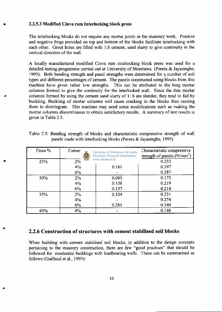
A locally manufactured modified Cinva ram interlocking block press was used for a detailed testing programme carried out at University of Moratuwa (Perera & Jayasinghe, 1995). Both bending strength and panel strengths were determined for a number of soil types and different percentages of cement. The panels constructed using blocks from this machine have given rather low strengths. This can be attributed to the long mortar columns formed to give the continuity for the interlocked wall. Since the thin mortar columns formed by using the cement sand slurry of 1: 6 are slender, they tend to fail by buckling. Buckling of mortar columns will cause cracking in the blocks thus causing them to disintegrate. This machine may need some modifications such as making the mortar columns discontinuous to obtain satisfactory results. A summary of test results is given in Table 2.5.
Table 2.5: Bending strength of blocks and characteristic compressive strength of wall panels made with interlocking blocks (Perera & Jayasinghe, 1995)
Fines % Cement % Bending strength (N/mm 2)
Characteristic compressive strength of panels (N/mm )
25% 2% 0.104 0.233 4% 0.181 0.197 6% - 0.287
30% 2% 0.095 0.173 4% 0.158 0.219 6% 0.157 0.214
35% 2% 0.104 0.231 4% - 0.274 6% 0.281 0.340
40% 4% - 0.148
2.2.6 Construction of structures with cement stabilised soil blocks
When building with cement stabilised soil blocks, in addition to the design concepts pertaining to the masonry construction, there are few "good practises" that should be followed for residential buildings with loadbearing walls. These can be summarised as follows (Guillaud et al., 1995):
16

1. Limitations on the plan layouts and opening sizes: The designer should be willing to adopt simple building systems that are compatible with the properties of the blocks such as good compressive strength, but low tensile, bending and shear strengths.
2. Protection of building elements: The designer should be willing to adopt design principles and building solutions, which are suitable for building with earth. These can be the use of large eaves or water repellent coatings to reduce the excessive moisture movements which is a main cause of degradation.
3. Quality controlling: It is necessary to ensure that the execution of the building work is carefully carried out with certain level of quality controlling. This is especially true for loadbearing cement stabilised soil block construction since the material strengths obtained with economical low cement contents are just sufficient to satisfy the safety margins imposed by the partial factors of safety used in masonry design.
With due consideration to these good practices, cement stabilised soil blocks have been successfully used for single storey houses, two storey houses with loadbearing walls, and multi-storey buildings such as hostel buildings (Guillaud et al., 1995, Middleton, 1985). These structures have been constructed in a number of countries including France, Australia, Morocco, Guyana, Saudi Arabia, India etc.
2.2.6.1 Foundations for cement stabilised soil block buildings
The foundations should fulfil two functions in buildings constructed with cement stabilised soil blocks. Those are as follows (Houben & Guillaud, 1989):
1 .provision of adequate distribution of wall loads to prevent failure of soils below the foundation and to provide adequate strength against disintegration of foundation due to settlements or earthquakes.
2. minimisation of ingress of moisture through the foundation since earth is inherently vulnerable to fluctuations in moisture content.
Thus the use of good foundation material such as random rubble masonry will be essential. Proper drainage also should be provided around the foundations.
The possibility of providing a reinforced concrete tie beam at the plinth level should also be considered. It was shown by Jayasinghe & Maharachchi (1998) that provision of a tie beam at window sill level can serve the dual purposes of reducing cracks due to thermal movement while enhancing the resistance of the structure to foundation settlements. It was reported by McHendry & May (1984) that the provision of adequate continuity by using reinforcement can enhance the earthquake resistance of stabilised soil walls.
17

2.2.6.2 Plasters and coatings
According to Bryan(1988 b), surface erosion could occur when driving rain or abrasive wind blown sand causes mechanical damage and then wash away the loosened material. Thus, when soil is used for building construction, good detailing and stabilisation could eliminate this problem. Many sheltered cob walls, which was a traditional earth construction in United Kingdom, has survived without any surface coatings over long durations sometimes exceeding one hundred years (Saxton, 1995).
For the climatic conditions prevailing in Sri Lanka, resistance to rain penetration is one of the most important functions of a building envelope. This should be achieved by controlling the rain penetration resistance of masonry walls (Chandrakeerthy, 1991 a).
Rain penetration is defined as the penetration of water into a wall either through the surface of the wall or through leakage at openings such as windows and doors. Common entry paths are through pores in the face of the masonry units and mortar, through cracks in masonry units and mortar, or through improperly sealed cracks between masonry and other building elements. Such entry paths can be substantially cut off in walls when external finishes such as renderings are applied. It is also possible to use large overhangs for these buildings.
As regards to rain penetration, bond strength of mortar is more important than its compressive strength. Thus the use of lime in mortar is preferred in this respect since it improves the workability and water retentivity of mortar, which is essential for maximum bond (Chandrakeerthy, 1991 a). It was reported Jamal & Sheikh (1987) that cement stabilised soil block walls can be made water resistant by painting them with liquid sodium silicate. It was recommended to apply three coats of sodium silicate at two-day intervals to the exterior walls.
2.2.7 Soil blocks with Aurum Press 3000
An extensive experimental programme was carried out by Jayasinghe (1999) for cement stabilised soil blocks using Aurum Press 3000. The aim was to popularise the use of soil blocks for both single and two storey houses.
There are two block sizes that can be easily adopted for houses. For load bearing two storey constructions, 240 x 240 x 90 mm (length x width x height) blocks can be used. For single storey houses or the upper floor of two storey houses, 290 x 140 x 90 mm blocks can be used.
These blocks were manufactured with compaction ratio of 1.65. Compaction ratio is defined as the volume of soil prior to compaction to volume of the block. Since the cross section is the same, the compaction ratio is given by the height of the soil in the mould to
18

LIBRARY
MORATUWA
the height of the block. The minimum compaction ratio recommended by Jayasinghe (1999) is 1.65 considering strength and durability.
The experimental programme covered block strengths, wall strengths and bending strengths that can be used for quality controlling purposes. These results are presented in tabular form in Tables 2.6 to 2.11 as reported by Jayasinghe (1999)
Table2.6: Average block strength Vs fines content for different percentages of cement with moist cured and uncured 290 mm x 140 mm x 90 mm blocks (28 day strengths) Jayasinghe C. (1999)
Fines % Cement % Compressive Average Average strength of cured compressive compressive blocks (N/mm 2) strength of cured strength of uncured
blocks (N/mm 2) blocks (N/mm 2)
20 2 1.40, 1.13, 1.55 1.36 1.07 4 2.36, 2.68, 2.44 2.49 1.57 6 3.30,2.79,3.36 3.15 1.77 8 4.14,4.04, 4.70 4.30 3.49
25 2 1.70, 1.87, 1.95 1.84 1.20 4 2.70,3.05,2.10 2.62 2.81 6 2.56,3.16,3.10 2.94 2.62 8 4.26,3.88,3.87 4.00 2.45
30 2 1.70, 1.95, 1.33 1.66 1.78 4 3.96, 3.97, 2.03 3.32 2.03 6 4.04, 3.80, 3.86 3.90 2.69 8 3.97, 3.98, 3.97 3.97 2.40
40 2 1.03, 1.28, 1.07 1.13 -4 2.26, 1.74, 1.80 1.93 -6 2.60, 2.70, 2.80 2.70 -8 2.89, 2.80, 2.98 2.89 -
45 2 1.08, 1.00, 1.04 1.04 -4 1.70, 1.83, 1.84 1.79 -6 2.13,2.07,2.30 2.17 -8 3.47,3.13,3.40 3.33 -
19
85383
W , J / £ o

Table 2.7: Panel strength vs block strength for different percentages of cement with cured 290 mm x 140 mm x 90 mm blocks (28 day strengths) Jayasinghe C. (1999)
Fines % Cement Average compressive Average Characteristic % strength of blocks compressive compressive strength
(N/mm 2) strength of panels of panels (N/mm 2) (N/mm 2)
20 2 1.36 1.27 1.053 4 2.49 0.964 0.803 6 3.15 1.11 0.916 8 4.30 1.545 1.287
25 2 1.84 0.94 0.783 4 2.62 1.225 1.021 6 2.94 1.183 0.986 8 4.00 1.694 1.41
30 2 1.66 0.91 0.753 4 3.32 1.18 0.983 6 3.90 1.34 1.120 8 3.97 1.44 1.200
40 2 1.13 0.53 0.44 4 1.93 0.67 0.558 6 2.70 1.045 0.871 8 2.89 1.075 0.896
45 2 1.04 0.46 0.383 4 1.79 0.925 0.771 6 2.17 0.85 0.703 8 3.33 1.04 0.866
20

Table 2.8: Average bending strength Vs fines content for different percentages of cement with moist cured 290 mm x 140 mm x 90 mm blocks (28 day strengths) Jayasinghe C. (1999)
Fines % Cement % 2" Average bending strength of blocks (N/mm )
20 2 0.116 4 0.184 6 0.208 8 0.327
25 2 0.109 4 0.160 6 0.184 8 0.273
30 2 0.072 4 0.191 6 0.289 8 0.257
40 2 0.084 4 0.163 6 0.249 8 0.342
45 2 0.085 4 0.187 6 0.259 8 0.244
Table 2.9: Characteristic compressive strength of panels for different cement percentages and fines content < 30% Jayasinghe C. (1999)
Cement percentage by volume (%)
Characteristic compressive strength of panels (N/mm )
2 0.86 4 0.94 6 1.00 8 1.30
21

Table 2.10: Characteristic compressive strength of panels for different cement percentages and fines content of 40% - 45% Jayasinghe C. (1999)
Cement percentage by volume (%)
Characteristic compressive strength of panels N/mm
2 0.41 4 0.66 6 0.79 8 0.88
The following strength relationships are presented by Jayasinghe (1999) based on the above results.
Table 2.11: Characteristic panel strength Vs average bending strength for different percentages of cement with cured 290 mm x 140 mm x 90 mm blocks Jayasinghe C. (1999)
Fines % Cement % Characteristic compressive
strength of wall panels (N/mm 2)
Average bending strength of blocks
(N/mm 2)
20 2 1.053 0.116 4 0.803 0.184 6 0.916 0.208 8 1.287 0.327
25 2 0.783 0.109 4 1.021 0.160 6 0.986 0.184 8 1.41 0.273
30 2 0.753 0.072 4 0.983 0.191 6 1.120 0.289 8 1.200 0.257
40 2 0.44 0.084 4 0.558 0.163 6 0.871 0.249 8 0.896 0.342
45 2 0.383 0.085 4 0.771 0.187 6 0.703 0.259 8 0.866 0.244
22

1. For soils with fines content between 20% - 30%, the characteristic compressive strength of walls is approximately given by 0.15a c + 0.55 where a c is the average compressive strength of the blocks.
2. For soils with fines content above 30% and up to 45%, the characteristic compressive strength of walls is approximately given by 0.20a c + 0.2 where a c is the average compressive strength of blocks
3. For soils with fines content between 20% - 30%, the characteristic compressive strength of walls is approximately given by 2rjb + 0.6 where c»b is the bending strength of the blocks.
4. For soils with fines content above 30% and up to 45%, the characteristic panel strength is approximately given by 2.0c?b + 0.25 where Ob is the bending strength of the blocks.
It can be seen that the cement stabilised soil blocks can be adopted as a good partition material in large structures since it can be used even for load bearing construction.
2.3 HAND MOULDED CHIP CONCRETE BLOCKS
An alternative suggested for the popular cement mortar block is chip concrete blocks. Initially, it was introduced as hand moulded chip concrete blocks by Jayasingha (2002). The idea was to cater for rural communities who will not be able to raise sufficient capital for bulk purchasing materials for wall construction. The ability to manufacture chip concrete blocks with the free time and gathering the required amount of blocks gradually over 2-3 months is very attractive when the capital is in short supply, but purchasing of raw materials is affordable.
Another key advantage of chip concrete blocks was the low usage of cement with mixes like 1:8:14 cement: sand: chips. This gives a mix of 1:22 instead of 1:10 or 1:12 usually used for cement mortar block manufacturing. Hands moulded blocks are manufactured as solid blocks.
The technical data available for hand moulded chip concrete blocks is very important for the present study. Although hand moulded blocks would not be feasible for large-scale projects under consideration, it can provide an insight into the characteristics that can be obtained with lower use of cement. This information can be used to develop a suitable machine moulded chip concrete block.
23

2.3.1 Selection of mix proportions
When selecting the mixes for block making with hand moulded blocks special attention was placed to minimise the usage of cement while achieving the required strength (Jayasinghe 2002). If the mix proportions are considered as cement: aggregate the mixes would be equivalent to 1 : 19, 1 : 22 , 1 : 25 and 1 : 28.
2.3.2 Manufacturing of blocks
For the manufacturing of blocks cement and fine aggregates were mixed. Then chips were placed on it and water was sprayed prior to mixing. The amount of water used was just sufficient to give a reasonably dry mix, so that the mould could be removed immediately after casting of the block. The water cement ratio was 0.9 for all the mixes. This appears as unrealistically high value for concrete.
However it occurs due to the use of very lean mixes where the cement to total aggregate ratio by volume varies between 1:15 to 1:22. Compaction was done manually with a 50mm. x 50mm. hammer weighing about 1.0 kg.
2.3.3 Compressive strength of hand moulded blocks
For each mix, three blocks were tested after 7 days, 28 days and 2 months. The strengths given in Table 2.12 were obtained for hand moulded chip concrete blocks by Jayasinghe 2002.
The blocks were uncapped for 3 and 7 days and were capped for 14 days and 28 days. SLS Part 1: 1989 allows the testing of both capped and uncapped blocks. The width of the block was 125mm.
Table 2.12: Results obtained by Jayasinghe (2002) for HMCC blocks with sand and quarry dust (Q.D.) as fine aggregates
Mix Average Compressive Strength N/mm Proportions
3 day 7 day 14 day 28 day
Sand Q.D. Sand Q.D. Sand Q.D. Sand Q.D.
1:7:12 1.86 1.16 2.03 1.27 2.31 1.33 2.73 1.65 1:8:14 1.23 0.87 1.88 1.19 2.03 1.40 1.83 1.73 1:9:16 1.05 0.61 1.45 1.24 1.37 1.48 1.88 1.52 1:10:18 0.83 - 0.87 - 1.08 - 1.38 -
It is recommended in SLS 855: Part 1: 1989, that the cement sand blocks should have a compressive strength of 1.2 N/mm 2 All mix proportions satisfied the conditions. The mix proportion of 1:8:14 cement: fine aggregates: chips had been selected for the detailed programme on block walls. The use of a mix weaker than this would not be desirable from the durability point of view.
It should be noted that there could be a certain scatter in the block strengths reported since the actual strengths of blocks will not depend only on the age, but the compaction effort and the degree of curing. For example, for 1:8:14 mix, the seven day strength with sand is usually higher and it is marginally over the strength value obtained for 28 days.
For all these blocks, the greatest strength increase has occurred over the first three days and generally upto seven being. After that the strength gain is to a lesser extent upto the 28 days. Thus, curing of blocks for the first seven days will be extremely important. This could be achieved by keeping the blocks moist by covering with a polythene sheet.
2.4 CONCRETE FLOOR SYSTEMS
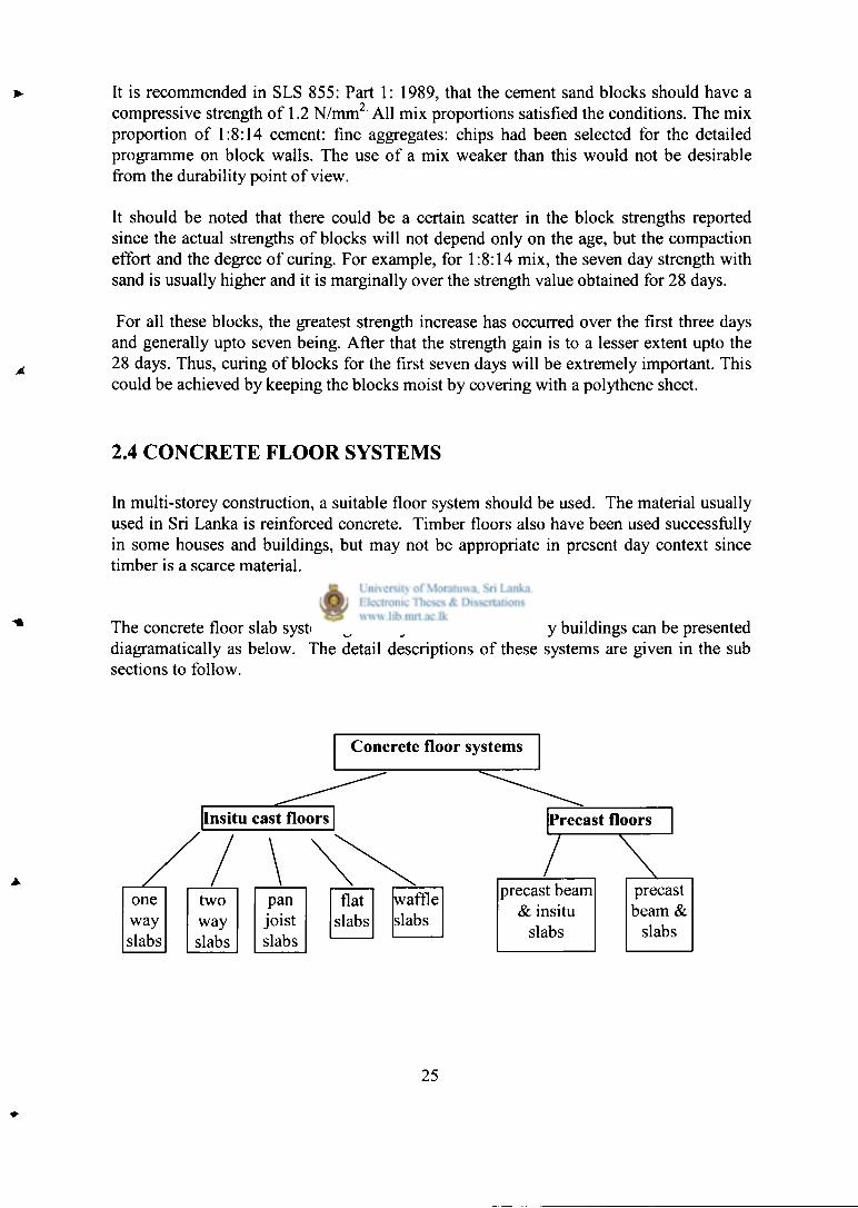
In multi-storey construction, a suitable floor system should be used. The material usually used in Sri Lanka is reinforced concrete. Timber floors also have been used successfully in some houses and buildings, but may not be appropriate in present day context since timber is a scarce material.
The concrete floor slab systems generally used in multi-storey buildings can be presented diagramatically as below. The detail descriptions of these systems are given in the sub sections to follow.
Concrete floor systems
one two pan way way joist slabs slabs slabs
flat slabs
waffle slabs
precast beam precast & insitu beam &
slabs slabs
25

2.4.1 Floor systems used in multi-storey buildings
An appropriate floor system is an important factor in the overall economy of two storey houses. Reinforced concrete floor systems can be grouped into two categories:
i. one-way slabs in which the slab spans in one direction between supporting beams and walls
ii two-way slabs, in which the slab spans in orthogonal directions.
In both systems, advantage of continuity over interior supports is utilised by providing negative moment reinforcement in the slab.
The floor systems that have been used in buildings can be categorised as follows (Smith &Coull 1991):
1. one way slabs on beams or walls,
2. two way slabs on beams or walls,
3. one way pan joists and beams,
4. one way slab on beams and girders,
5. two way flat plate,
6. two way flat slab, and
7. waffle flat slab.
2.4.1.1 One way slabs on beams and walls
A solid slab up to 200 mm thickness, spanning continuously over walls or beams up to 7.5 m apart provides a floor system requiring simple formwork with simple reinforcement.The thickness used for residential buildings vary between 115 mm to 150 mm. This system is heavy and inefficient in its use of both concrete and reinforcement (Smith & Coull, 1991).
2.4.1.2 Two-way slab on beams
The slab spans two ways between orthogonal set of beams that transfer the load to the columns and walls.The two way system allows a thinner slab and is economical than one
26

way slabs in the utilisation of concrete and reinforcement. The maximum length-to-width ratio for a slab to be effective in two directions is approximately 2 (BS 8110, 1985).
2.4.1.3 One way pan joists and beams
A thin, mesh-reinforced slab sits on closely spaced cast-in-place joists spanning between major beams which transfer the loads to the columns. The slab may be as thin as 60 mm while the joists are in 150 mm to 500 mm in depth and spaced 600 mm to 900 mm. The slab acting in composite with joists form in effect a set of closely spaced T-beams capable of spanning up to 12 m (Smith & Coull, 1991).
2.4.1.4 One-way slab on beams and girders
A one-way slab spans between beams at a relatively close spacing while the beams are supported by girders that transfer the load to the columns . The short spanning slab may be thin, from 75 mm to 150 mm thick, while the system is capable of providing long spans up to 14.0 m (Smith & Coull, 1991).
2.4.1.5 Two way flat plate
The uniformly thick, two way reinforced slab is supported directly by columns or individual short walls. It can span up to 8.0 m in the ordinary reinforced form and up to 11.0 m, when post-tensioned, specially in apartment and residential buildings where the imposed loads are not large. It can be economical in buildings due to saving obtained with simple formwork and reinforcement (Taranath, 1988).
2.4.1.6 Two way flat slab
The flat slab differs from the flat plate in having column heads and drop panels. The column heads increase the shear capacity while the drop panels increase both the shear and negative moment capacities at the supports, where the maximum values occur. Thus, two way flat slabs can carry heavier loads than flat plate (Taranath, 1988).
2.4.1.7 Waffle flat slab
A slab is supported by a square grid of closely spaced joists with filler panels over the columns. These joists carry loads simultaneously in both directions. The slabs and joists are pored integrally over square, domed forms that are omitted around the columns to form the filler panels. The forms which are of sizes up to 750 mm square and up to
27

500 mm deep provide a geometrically interesting soffit, which is often left without further finish (Taranath, 1988).
2.4.2 Alternative floor systems used for buildings in Sri Lanka
The conventional one way solid slabs, two way solid slabs and flat slabs have been used in buildings of Sri Lanka. However, due to shortage of timber and bamboos used for shuttering work, a number of alternative systems have been developed recently. These systems minimise the usage of formwork and falsework. They can be identified as:
1. Precast prestressed concrete beam and insitu cast slab system developed at National Engineering Research and Development centre (Kulasinghe,1998).
2. Precast prestressed concrete beam slab system with hollow blocks finished with a screed.
3. Precast reinforced concrete beam and slab system developed at University of Moratuwa, Jayasinghe & Perera (2000).
2.4.2.1 Precast prestressed concrete beam and insitu cast slab systems
This system consists of precast prestressed concrete beams of trapezoidal shape. The beams are cast with heights varying from 100 mm to 175 mm. Since prestressed concrete beams are used, those should be manufactured at factory conditions. These beams are recommended for spans varying from 3.0 m to 6.0 m. Those are located at 600 mm centres and a 50 mm slab is constructed by using a shuttering suspended from the beams. The reinforcement used for the slab is only 50 mm x 50 mm square mesh with 3 mm diameter wires. In this system, precast beams spaced at 600 mm centres can be seen from below.
The reinforced concrete slab of 50 mm thickness is cast using prefabricated shutter panels, which are suspended from the precast beams with binding wire. The top of the shutter, which is lined with a removable thin plastic liner, is kept one inch below the top of the precast beam. The reinforcement mesh is supported on top of the precast beams and a 50 mm thick concrete is cast embedding 25 mm of the beam. No props are required except for long spans of over 4.5 m where a prop is placed at the centre of the precast beams to prevent unacceptable deflections (Kulasinghe, 1998).
2.4.2.2 Precast prestressed concrete beam and slab systems with hollow blocks
This floor system consists of precast prestressed concrete beams spaced at 572 mm, which support infill blocks spanning between them. This floor system is similar to that
28
reported by Moss (1993). A 50 mm thick screed is laid on top of this system to give a continuous top surface.
The reinforcement is 50 mm x 50 mm square mesh or 6 mm diameter mild steel bars at 200 mm centres in both ways. The main advantage of this system is that it gives a flat soffit. No formwork or falsework is required for the construction.
2.4.2.3 Precast reinforced concrete beam and slab system
This system differs from the above two systems in the use of reinforced concrete beams instead of prestressed concrete beams. These are of length 1.5 m. Therefore, they can be placed on precast beams located at 1.5 m spacing. The thickness of the slab after the placement of insitu concrete is only 75mm. The reinforcement recommended for residential application is 3 Nos. of 6 mm diameter bars. Therefore, there is a substantial saving in the reinforcement and concrete. Precasting almost eliminates the need for formwork and falsework. The slab system can be manufactured without any specialized equipment and hence could be adopted for any building in any part of the country. Therefore it is adopted for the present study. Another advantage of this system is that it can be designed for BS 8110: Parti: 1985 Jayasingha & Perera (2000). This is particularly important when adopting the system for larger buildings since the imposed loads is different.
2.5 SUMMARY
A detailed literature review is presented on alternative building materials developed or adopted in Sri Lanka for the residential buildings. They include cement stabilised soil blocks, chip concrete blocks and precast reinforced concrete slab system.
The strength characteristics of cement stabilised soil blocks indicate the potential for applying them in larger buildings. The chip concrete blocks also indicate a similar possibility. These may be particularly suitable as infill panels in larger buildings since the loadbearing function would be carried out by the reinforced concrete frame.
The adoption of precast reinforced concrete slab will need some careful consideration since the floor slab acts as a rigid diaphragm in reinforced concrete frame buildings. It also needs to be designed for the imposed loads that can be expected in large buildings.
The adoption of these alternative building materials will be a significant deviation of the established practice for large buildings. However, it is worth exploring the cost implications of adopting alternative materials since they have the potential to reduce the amount of building materials needed for construction. This can have significant benefits in environmental terms by way of reducing the adverse effects on the environment.
29

Chapter3
MACHINE MOULDED CHIP CONCRETE BLOCKS
3.1 INTRODUCTION
In order to determine the suitability of chip concrete for the production of machine moulded chip concrete blocks (MMCC blocks), an experimental programme was carried out under the present research. This chapter presents the details and the results.
3.2 TESTING PROGRAMME ON MACHINE MOULDED CHIP CONCRETE BLOCKS.
The alternative commonly used for the brickwork is the cement sand blockwork. Generally, the blocks available in the market have a length of 390 mm and a height of 200 mm. The width of the blocks could be 100 mm or 150 mm or 200 mm. Use of blockwork has many advantages since it is possible to avoid internal and external plastering in carefully constructed block walls. The blocks manufactured in Sri Lanka should comply with SLS 855: Part 1: 1989: the specification for cement blocks. This standard allows the use of cement and a suitable aggregate for the manufacturing of blocks. At present, sand and quarry dust is extensively used.
3.2.1 Objectives of the experimental programme
The experimental research programme on Machine Moulded Chip Concrete (MMCC) Blocks had been carried out to achieve the following objectives:
1. To evaluate the cost effective mix proportions that could be used for MMCC blocks.
2. To determine the strength characteristics of blocks and to select a suitable mix for manufacturing MMCC blocks.
3.2.2 The methodology
In the experimental research programme on Machine Moulded Chip Concrete Blocks, the following methodology was adopted.
30

3.2.2.1 Selection of mix proportions
Four different types of mix proportions were selected for the testing programme. Mix proportions of cement: sand: quarry dust: chips were selected as 1:5:5:5. 1:4:3:10, 1:4:3:12 and 1:4:4:14 to manufacture blocks.
3.2.2.2 Manufacturing of Machine Moulded Chip Concrete Blocks
The machine moulded chip concrete blocks with different mix proportions of cement: sand: quarry dust: chips were cast using a normal block making machine. Two unskilled labourers can cast 60 blocks per hour. The manufacturing of blocks was done in the Sri Sudarshana Bimbaramaya temple at Malamulla, Panadura. They were cured by using wet gunny bags.
3.2.2.3 Testing of the Machine Moulded Chip Concrete Blocks for strength
The blocks manufactured with above mix proportions were tested at 3 days, 7 days, 28 days and 2 months to determine the strengths and the rate of strength development. Also the shrinkage tests were done for the manufactured blocks with different mixes.
3.2.2.4 Testing of the Machine Moulded Chip Concrete Blocks for shrinkage
The blocks manufactured with above mix proportions were tested were tested for shrinkage to determine the drying shrinkage of chip concrete blocks. Six specimen were tested for their wet readings and dry readings to calculate the value of drying shrinkage
3.3.1 The manufacturing of Machine Moulded Chip Concrete Blocks
When selecting the mixes for block making, special attention was placed to minimize the usage of cement while achieving the required strength. Therefore, machine moulded chip concrete blocks with different mix proportions of cement: Sand: quarry dust: chips were cast. Mix proportions used to cast blocks are 1:5:5:5. 1:4:3:10, 1:4:3:12 and 1:4:4:14.
For the manufacturing of blocks, cement and fine aggregates were mixed. Then chips were placed on it and water was sprayed prior to mixing. The amount of water used was just sufficient to give a reasonably dry mix so that the mould could be removed immediately after casting of the block moulded by machine. The length of the block is 400 mm. and the width is 100 mm. The height of the block is 210 mm.
For each mix, blocks were cast to carry out shrinkage tests and to find out the compressive strengths at ages of 7 days, 28 days and 2 months.
31

3.3.2 Testing of Machine Moulded Chip Concrete Blocks for compressive strength
Machine Moulded Chip Concrete Blocks with the mix proportions of cement: Sand: quarry dust: chips 1:5:5:5. 1:4:3:10, 1:4:312 and l:4:4:14.were tested after curing for the compressive strengths at ages of 7 days, 28 days and 2 months. Three sample blocks were tested for each test using the 200 Tonne compression testing machine available at the structural testing laboratory of Department of Civil Engineering.
3.3.2.1. Compressive Strength of Machine Moulded Chip Concrete Blocks
For each mix, three blocks were tested at the ages of 7 days, 28 days and 2 months. The results are given in Table 3.1.
Table 3.1 Crushing strengths of M.M.C.C. Blocks after 7 days, 28 days and 2 months
Mix Proportion Reading after 7 days (Tonne)
Reading after 28 days ((Tonne)
Reading after 60days(Tonne)
1:5:5:5 6 . 0 , 7 . 6 , 11.0 11.56, 12.2, 11.5 17.8, 18.9, 14.0 1:4:3:10 8.4 , 9.5 , 8.0 9 . 4 , 9 . 4 , 13.1 14.7, 14.4, 12.0 1:4:3:12 8.7 , 7.0 , 8.2 13.5, 13.5, 11.4 13.4, 15.4, 15.1 1:4:4:14 8.8, 12.2 , 11.5 11.4, 15.2, 13.1 14.8, 14.3, 13.5
3.3.2.2. Compressive strengths of the Machine Moulded Chip Concrete Blocks
The compressive strengths of the Machine Moulded Chip Concrete Blocks were calculated and the results given in Table 3.2 were obtained. Table 3.3 gives the average compressive strengths values.
Table 3.2 Compressive strengths of M.M.C.C. Blocks with different mixes
Mix proportion
Compressive strength N/mm
7 day 28 day 2 mont is 1:5:5:5 1.50 1.90 2.75 2.89 3.05 2.88 4.45 4.73 3.50
1:4:3:10 2.10 2.38 2.00 2.35 2.35 3.28 3.00 3.80 3.43 1:4:3:12 2.18 1.75 2.05 3.38 3.38 2.85 3.35 3.85 3.78 1:4:4:14 2.20 3.05 2.88 2.85 3.80 3.28 3.70 2.83 3.37
32
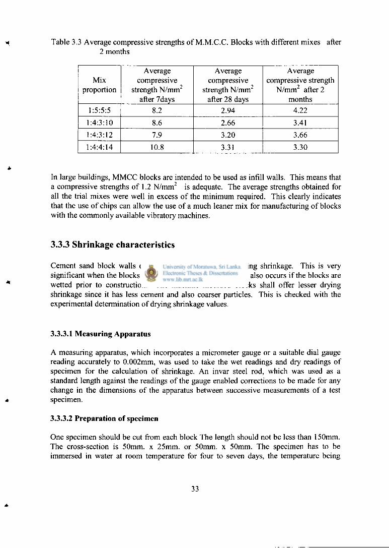
Table 3.3 Average compressive strengths of M.M.C.C. Blocks with different mixes after 2 months
Mix proportion
Average compressive
strength N/mm 2
after 7days
Average compressive
strength N/mm 2
after 28 days
Average compressive strength
N/mm 2 after 2 months
1:5:5:5 8.2 2.94 4.22
1:4:3:10 8.6 2.66 3.41 1:4:3:12 7.9 3.20 3.66 1:4:4:14 10.8 3.31 3.30
In large buildings, MMCC blocks are intended to be used as infill walls. This means that a compressive strengths of 1.2 N/mm 2 is adequate. The average strengths obtained for all the trial mixes were well in excess of the minimum required. This clearly indicates that the use of chips can allow the use of a much leaner mix for manufacturing of blocks with the commonly available vibratory machines.
3.3.3 Shrinkage characteristics
Cement sand block walls often develop cracks due to drying shrinkage. This is very significant when the blocks are used just after the casting. It also occurs if the blocks are wetted prior to construction. The machine moulded blocks shall offer lesser drying shrinkage since it has less cement and also coarser particles. This is checked with the experimental determination of drying shrinkage values.
3.3.3.1 Measuring Apparatus
A measuring apparatus, which incorporates a micrometer gauge or a suitable dial gauge reading accurately to 0.002mm, was used to take the wet readings and dry readings of specimen for the calculation of shrinkage. An invar steel rod, which was used as a standard length against the readings of the gauge enabled corrections to be made for any change in the dimensions of the apparatus between successive measurements of a test specimen.
3.3.3.2 Preparation of specimen
One specimen should be cut from each block The length should not be less than 150mm. The cross-section is 50mm. x 25mm. or 50mm. x 50mm. The specimen has to be immersed in water at room temperature for four to seven days, the temperature being
33

maintained at 27 ± 3 °C at least for the last four hours. The specimens prepared for the testing are of size 150x 50x 50 mm. and six specimens were prepared.
3.3.3.3 Measurement of drying shrinkage
Immediately after removal of specimen from the water, the length of each specimen has to be measured to an accuracy of 0.002mm by the measuring apparatus mentioned in Section 3.3.3.1. Rotate the specimen in the frame and observe the minimum reading. Then reverse the specimen end to end and observe the minimum reading in the same way. Determine the average of the two readings.
The specimen shall then be dried for at least 44 hours in the oven. It should be noted that during the drying process additional wet specimens shall not be placed in the same oven and there shall be free access of air to all surfaces of the specimens. It is necessary to maintain a temperature of 50 ± 1 °C in the oven for drying specimens. The specimens shall then be removed from the oven and cooled for at least four hours in a desiccator containing solid calcium chloride or a saturated solution of calcium chloride. Each specimen shall then be measured at a temperature of 27 ± 3 °C.
This cycle of drying, cooling, and measuring has to be repeated until constant length is received. That is when the differences between two consecutive measurements are less than 0.005 mm. for a 150 mm. specimen, and prorate for a larger specimen. The last measurement taken is the dry measurement. After the dry measurement is taken, the length of the specimen has to be taken and this length is the dry length.
3.3.3.4 Calculation of drying shrinkage of the Machine Moulded Chip Concrete Blocks
The drying shrinkage is calculated for each specimen as the difference between original wet measurement and the dry measurement expressed as the percentage of the dry length The drying shrinkage of the machine moulded chip concrete blocks was calculated using the above results and are given in Table 3.4
Table 3.4 Drying shrinkage of machine moulded chip concrete blocks
Sample 1 2 3 4 5 6
Drying Shrinkage (%) 0.05 0.059 0.013 0.012 0.039 0.057
34

3.4 Summary
For large buildings, machine moulded chip concrete blocks may be a good alternative to brickwork. When used as solid blocks, these can be used as both external infill panels and internal partition walls. The determination of suitable mixes and the corresponding strength characteristics is important for cost effective adoption of these blocks.
It is shown with an experimental programme thatl:4:4:14 and 1:4:3:12 mixes can be used. The strengths at 28 days were above 3 N/mm 2 . The drying shrinkage is less than 0.06% specified in SLS 855 1989. Therefore, it can be used as an alternative to brick walls in large buildings.
35

Chapter 4
PRECAST REINFORCED CONCRETE FLOOR SYSTEM
4.1 INTRODUCTION
In this study, the adoption of the precast reinforced concrete beam slab system described in Section 2.4.2 for framed buildings was investigated. The reason for selecting this system is the availability of a well developed design technique since it can be designed using the recommendation given in BS 8110: Part I: 1985 as suggested by Jayasinghe (1999). When adopted for large building, it should be designed for higher imposed loads such as in the range of 2.5 kN/m 2 or more. It is also necessary to introduce a suitable design method for framed reinforced concrete buildings when the precast reinforced concrete floor system is used.
4.2 A COMPARISON BETWEEN SLAB SYSTEMS
A brief discussion on various aspects of the commonly used solid slabs and the proposed precast reinforced concrete beam slab system is presented. This is important to gain an insight to the reasons for promoting the alternative slab system for large buildings.
1. In solid slabs, the thickness is often governed by the need to control the deflections. The thickness of the slab should be maintained to keep the span/effective depth ratios within allowable limit to satisfy deflection requirements. Sometimes, even the reinforcement quantities adjusted to control the deflection. Therefore, the usage of concrete and reinforcement is not optimized in the slabs and hence the cost of floor slabs is considered as a major cost item by many builders.
2. An insitu cast reinforced concrete solid slab needs falsework and formwork, which may have only one or two reuses. The formwork material generally used by builders comprises bamboo poles and untreated rubber wood planks, which are not quite durable construction materials. Both these materials can be considered as depleting resources and hence the prices are increasing at a somewhat higher rate than the other construction materials.
3. The concrete below the neutral axis in a solid slab serves the purpose of providing depth and cover to reinforcement. The depth to the neutral axis from the compression face in a solid slab is about 10% - 20% of the effective depth. However, a reasonable thickness has to be used for a solid slab in order to satisfy the deflection requirements. Thus, the concrete below the neutral axis adds to the dead weight of the structure while providing durability to the reinforcement.
36

4. Insitu cast reinforced concrete slab construction process involves erecting of falsework and formwork, fixing of reinforcement, concreting and curing.
As an alternative to solid slabs, the precast reinforced concrete beam slab construction is proposed.
It has the following advantages.
1. It uses reinforced concrete for precast units, thus can be manufactured locally at the site with minimum involvement of skilled labour when a sufficient number of reusable formwork sets is available.
2. It can minimise the need for falsework and formwork required during the actual erection of the slab. However, the scaffolding needed for the workers can be marginally higher than the traditional construction to facilitate the erection of precast units.
3. Due to the presence of precast beams, there is a reduction in the spans of the slabs. This can be used very effectively to reduce the depth required for controlling the deflection of the slabs. This will lead to a reduction in the quantity of concrete required with a corresponding reduction in the quantity of steel required. When the depth of the slab panel is low, flexural reinforcement requirement could be governing the reinforcement provided.
4. The precast slab panels, which are used for the erection of composite slabs, can be cast with a sufficient time lag so that the chances of cracking due to shrinkage of concrete will be remote.
5. When reduction of total construction duration is important, precasting of members can be quite useful. With this composite precast beam slab system, the construction duration of the floor slabs can be reduced to that of erecting the precast system and laying of insitu concrete to form the composite slab.
To adopt this slab system to large buildings, it should be designed for larger imposed loads.
4.3 THE DESIGN STUDY
It was shown by Jayasinghe & Perera (2000a) that the precast reinforced beam slab system can be designed for B.S. 8110: Part I: 1985 using design studies and full scale load testing. For this study, this alternative system was redesigned for higher loads that
37

would be acting in office building. The design of the slab system consists of the design of individual slab panels and the composite beam.
The design study was carried out with the following information. The design method used is same as that presented by Jayasinghe & Perera (2000) for the slab system.
1. The precast panels should be strong enough to carry the loads during construction and at service. A uniformly distributed imposed load of 4.0 kN/m 2
is considered which consists of a 2.5 kN/m 2 live load, 1.0 kN/m 2 of movable partition load and a load of 0.5 kN/m 2 for finishes. The concentrated load that could be expected in service is 2.7 kN (BS 6399: Part 1: 1984). It should be noted that such concentrated loads are not considered for structural design of solid slabs. However, this concentrated load is important in this case since the slab consist of individual precast panels connected with insitu cast concrete. The precast slab panels should also be able to support the weight of at least one person standing at the centre of a precast panel during construction. It should be noted that construction loads should be selected at the discretion of the design engineer. However, some guidelines may be obtained from BS 6399: Part 1: 1984 where it states that roofs and ceilings with access should be designed for a concentrated load of 0.9 kN. Thus, a construction load of 0.9 kN acting at the centre of a precast panel was also considered.
2. The precast beam in the composite slab system should be designed as a flanged beam. This means, it is desirable to have a sufficient insitu cast flange width for the precast beam The shape of the precast slab panels adopted to fulfill this requirement is shown in Figure 4.1 since there is a need to place insitu cast concrete to connect the precast panels. This is the panel shape used by Jayasinghe & Perera (2000a).
Figure 4.1 The shape of the precast panel used for composite slab
38

300 300 1500
(dimensions in mm)
300 PLAN
300 300
Figure 4.2 Plan & elevation of the pre cast slab panel
3. For a tapered length of 300 mm used in precast panels as shown in Figure 4.2, a width of 670 mm can be obtained for the flange of the beam when the precast panels are supported on a beam of width 150 mm. The precast panels should be provided with a bearing width of 40 mm. Thus, in order to determine the flange width to be used for the design calculations, the effective flange width can be calculated as for CI 3.4.1.5 of BS 8110: Part 1: 1985. This should be compared with the actual flange width of 670 mm and the lesser value should be adopted. The decision to limit the flange width to 670mm is an important one since the use of excessive tapered portions in one way precast slab panels may not be desirable with respect to carrying construction loads.
4. The use of the shape given in Figure 4.1 for precast slab panels also allows the placement of transverse reinforcement in the flange of the beam as given in Table 3.27 of BS 8110: Part 1: 1985.
5. It should be noted that the minimum thickness of the precast panel is limited to 40 mm. This is required to ensure sufficient capacity in resisting shear forces during construction.
6. In the middle portion of the precast slab panel, the width at the top was limited to 250 mm in order to provide connectivity between two adjacent precast panels by using insitu cast concrete as shown in Figure 4.3
39

Figure 4.3 The shape of the precast panel used for composite slab
7. For the precast slab panels, there was no intention to make them continuous over the precast beams. In CI 3.6.2 of BS 8110: Part 1: 1985, it is proposed that when slabs need not be made continuous, it is possible to curtail the top reinforcement at a distance of 0.15 of the span from the face of the support where top reinforcement will act only to prevent cracks at the top surface. The use of a tapered length of 300 mm in the slab panels will ensure that only a distance of 235 mm (300 - 40 - 25) will be available for the transverse reinforcement from the face of the beam. This length gives approximately 0.15 times the span (235/1500 = 0.1566).
8. The precast beam size selected was 200 mm in depth and 150 mm in width. The depth depends on the need for supporting the construction loads and controlling the deflection at service. The width required is just sufficient to provide a bearing width of 40 mm for each precast slab panel as specified in CI 5.2.3.2 of BS 8110: Part 1: 1985. This gives a clearance of 70 mm in between the precast slab panels as shown in Figure 4.4
670mm
200 mm
150mm
Figure 4.4 Composite flanged beam
40

4.3.1 Design of precast slab panels for construction and imposed loads
Precast slab panels selected with dimensions shown in Figure 4.2 should be designed for two different load cases.
1. Loads acting during construction.
2. Dead and imposed loads acting during service.
The loads acting during construction consists of the weight of workmen who would be walking on the panel. For this, a concentrated load of 0.9 kN acting at the centre of a panel was considered. During construction, load sharing between adjacent panels is not available. Thus, each panel should be designed for the total load acting on it. In order to obtain the design shear force, this concentrated load should be located at the ends of the precast panels.
When the precast panels are used to form a composite slab, it can be subjected either to uniformly distributed loads or concentrated loads. A uniformly distributed load of 2.5 kN/m 2 was considered as specified in BS 6399: Part 1: 1984 for general offices. Since this composite slab system consists of individual precast panels connected by insitu concrete, the behaviour of a panel subjected to a concentrated load of 2.7 kN is also important since excessive deflection of an individual panel due to a concentrated load may not be desirable. It was reported by Jayasinghe & Perera (2000b) that a slab will carry only about 66.7% of the load acting on it. Others will be shared by the adjacent panel. For these concentrated loads, there can be load sharing to a certain degree.
The design calculations performed for the precast slabs are given in Section A.5.3. The following can be summarised from these calculations:
1. The area of reinforcement required in the precast slab panels can be determined to satisfy flexural requirements at ultimate limit state in the longitudinal direction. In the transverse direction, the area of reinforcement required can be determined on the basis of minimum reinforcement required for crack controlling. The guidelines on the maximum clear distance between bars are also checked.
2. The shear carrying capacity of a panel should be evaluated at ultimate limit state for both construction loads and imposed loads. During construction, the shear capacity of a precast panel close to the support can be governing the design since the effective depth is reduced considerably due to the shape of the precast panel as shown in Figure 4.3. Once the insitu concrete hardens, a total depth of 75 mm will be effective at the supports.
3. The deflection should satisfy allowable span/effective depth ratios under service load conditions.

It can be seen from design calculations of precast slab panels that the following reinforcement areas are required in the longitudinal direction.
1. The longitudinal reinforcement area required to support construction loads is 77.10 mm" of mild steel as given in Section A.3.1.3
2. The longitudinal reinforcement area required to support a uniformly distributed load of 3.5 kN/m" is 73.26 mm" of mild steel as given in Section A.3.1.1.
3. With load sharing the reinforcement area required to support a point load of 2.7 kN acting at the centre of a panel is 77.4 mm 2 of mild steel as given in Section A. 3.1.4.
As the reinforcements of precast panel, 2 numbers of 6 mm diameter mild steel bars and one number of 8mm. diameter mild steel bar which give an area of 106.9 was selected. This satisfies the recommendations given by Jayasinghe & Perera (2000b) that 2/3 or 66.67% of the concentrated load could be taken by an edge panel or interior panel when load sharing is available
4.3.2. Design of precast beams for construction loads and imposed loads
The composite slab system consists of precast beams and precast slabs connected by insitu cast concrete. The composite slab system is designed for a superimposed dead load of 0.5 kN/m" representing a 20 mm cement rendering and an imposed load of 2.5 kN/m".
In the design of composite system, only the reinforced concrete flange beam needs to be designed since the precast slab panels have already been designed. For the structural design of the beam, a flanged beam of the shape given in Figure 4.4 was used. The precast slab panels supported on the precast beam were ignored since those may not be resting against each other to form a continuous slab. Thus, those would not form a compression flange for the beam.
It was shown in Section A3.2 that the actual depth to the neutral axis would only be about 15.25 mm and hence the compression zone will be within the depth of the flange. Thus, the design can be carried out as for a flanged beam having the neutral axis within the flange using BS 8110: Part 1: 1985.
The precast reinforced concrete beam should also be designed for construction loads. The construction loads consist of lifting stresses and the loads that act before the composite action is effective. During handling, the beam can be lifted in one of the ways shown in Figure 4.5. It is considered that the beam would be lifted at the ends, which will give a maximum sagging bending moment at the centre. Sufficient reinforcement should be provided to resist the flexural moments that would arise for either case.
42

reinforcement to be provided between two slab panels, which can be embedded in insitu cast concrete.
R 6
300 mm
1 f
t R 6 @ 150 c/c
4
R 8
1500mm R 6
Figure 4.6 Reinforcement details of precast slab panels
Figure 4.7 Arrangement of longitudinal and transverse crack controlling reinforcement within insitu cast concrete provided over the precast beam
43

4.4 ADOPTION OF PRECAST REINFORCED CONCRETE BEAM SLAB SYSTEMS FOR FRAMED BUILDINGS
In reinforced concrete insitu cast buildings, the floor slabs are expected to perform an important purpose. It is acting as a rigid diaphragm. This will prevent any local floor deformations on the plane of the reinforced concrete slabs. The alternative slab system consists of precast panels connected by insitu cast concrete with the provision of additional reinforcements. Therefore, it also cannot undergo any significant deformations on its own plane. Thus, this slab system can act as a rigid diaphragm.
For large buildings, the moments due to wind induced lateral loads can be significant. There are two ways of resisting these forces. It is possible to use either infill brick or blockwork panels. Alternatively, the frame can be designed as unbraced. Since there is a possibility to remove the infill panels at a latter date many designers prefer to consider the frame as unbraced. The alternative system also needs the main beam provided in one direction with the beam in perpendicular direction being optional. If the structure has to be designed as unbraced in two perpendicular directions, it is possible to use the following approaches.
1. In the direction of main beams, all the frames participate in resisting lateral loads. 2. In the direction of secondary beam, only the external frames participate in
resisting lateral loads
insitu cast beams in secondary beam direction
i
3.6m
0.3m
4.5m
1.5m
main beams
precz st beams at 1.5 m spacing to support the slabs
Figure 4.8 Slabs and beams arrangement in Building 1
44

ins i tu c a s t b e a m s in s e c o n d a r y b e a m d i r e c t i o n
6.0in — 1.5m
0.3m 3.6m m a i n b e a m s
precast beams at 1.5 in spacing to support the : abs
Figure 4.9 Slabs and beams arrangement in Building 2
This approach gives a sound design principle that can be adopted for framed buildings with the precast slab system. Since it can carry the loads that can be expected in office buildings this alternative slab system that uses less concrete, steel, formwork and false work should be considered seriously for actual adoption.
This system was used in two numbers of three storied buildings with reinforced concrete frames designed as unbraced. Figure 4.10 and Figure 4.11 show these two buildings. Figure 4.10 shows the Building 1 with grids at intervals of 4.5m and 3.6m. Figure 4.11 shows the Building 2 with grids at intervals of 6.0m and 3.6m. Both these buildings, Building I and Building 2 are of same length and same width. The length is 28.8 m. The width is 18.0 m.
The composite slab system consists of precast beams and precast slabs connected by insitu cast concrete. The design for this section is given in Appendix A of the thesis. Precast beams which carry the load of the composite slab are kept on insitu-cast concrete beams.
All the other structural elements other than the composite slabs and precast beams are designed according to the BS 8110: Parti: 1985 using the typical design method. The main beams, secondary beams, columns, foundations and stair cases of these two buildings are of insitu cast concrete and they are designed according to the BS 8110: Parti: 1985. The bearing capacity of the soil is assumed as 200 kN/m 2.
45

3.6m
j
-
3.6m
-
3.6m
-
, 1
E
28.8
m
, 1
E *o
28.8
m
3.6m
28.8
m
e
28.8
m
G
4 . 5m 4 . 5m 4 .5m 4.5 m
IR.<
Figure 4.10 Plan of the Building 1 with grid intervals at 3.6 m. and 4.5 m. intervals
3.6m
3.
6m
3.6m
3.
6m
1 1
28.8
m
3.6m
1 1
28.8
m
3.6m
-
3.6m
-
3.6m
-
6 . 0 m 6 . 0 m 6 . 0 m
18.0in
6 . 0 m
Figure 4.11 Plan of the Building 2 with grid intervals at 3.6 in. and 6.0 m. intervals
46

4.5 SUMMARY
In this chapter, the adoption of the precast reinforced concrete beam slabs constructions for large buildings was presented. The reinforcement requirements were decided for precast slab panels and beams for an imposed load of 2.5 kN/m 2 recommended for office buildings. An allowance of 1.0 kN/m 2 was used for movable partitions. A load of 0.5 kN/m 2 was allowed for finishes. The structural concepts needed for the design of framed buildings that utilizes the alternative slab system is highlighted
Two numbers of three storied framed buildings Building 1 and Building 2 were considered for the study of this alternative system. Theses two buildings are of the same length of 28.8 m and width of 18.8 m. The grid intervals of Building 1 are 3.6 m. and 4.5 m. The grid intervals of Building 2 are 3.6 m. and 6.0 m.
In order to carry out the cost study for these two buildings, it was required to design all the structural elements other than the composite slab and precast beams for the preparation of Bill of Quantities for Building 1 and Building 2. These structural elements were designed according to the BS 8110: Parti: 1985 using the typical design method.
47

4.5 SUMMARY
In this chapter, the adoption of the precast reinforced concrete beam slabs constructions for large buildings was presented. The reinforcement requirements were decided for precast slab panels and beams for an imposed load of 2.5 kN/m 2 recommended for office buildings. An allowance of 1.0 kN/m 2 was used for movable partitions. A load of 0.5 kN/m 2 was allowed for finishes. The structural concepts needed for the design of framed buildings that utilizes the alternative slab system is highlighted
Two numbers of three storied framed buildings Building 1 and Building 2 were considered for the study of this alternative system. Theses two buildings are of the same length of 28.8 m and width of 18.8 m. The grid intervals of Building 1 are 3.6 m. and 4.5 m. The grid intervals of Building 2 are 3.6 m. and 6.0 m.
In order to carry out the cost study for these two buildings, it was required to design all the structural elements other than the composite slab and precast beams for the preparation of Bill of Quantities for Building 1 and Building 2. These structural elements were designed according to the BS 8110: Parti: 1985 using the typical design method.
48

Chapter 5
THE COST STUDY
5.1 INTRODUCTION
The cost of construction is one of the key factors when decisions are taken about the adoption of alternative building materials. This wil l need the evaluation of the cost of alternative building materials on square meter basis. Walls can be constructed out of bricks, cement sand blocks, cement stabilized soil blocks, Hand Moulded Chip Concrete blocks (HMCC blocks), Machine Moulded Chip Concrete blocks (MMCC blocks) etc. In this cost study, cost comparison for the walls is done between brick walls and Machine Moulded Chip Concrete block walls. Floor slabs can be constructed using the conventional method of casting insitu concrete slabs and beams as well as keeping precast slabs on precast beams which are placed on in situ cast concrete beams and finally laying a reinforced screed on top connecting precast slab panels. In this cost study, cost comparison is done between these two methods.
When performing cost studies for project evaluation purposes, there are two different cost components, namely the actual cost and the cost that includes the provision for contingencies (10%), escalation (10%) and VAT (15%). This means that the actual cost on Bill of Quantities wil l be enhanced by about 35 % to detennine the projected cost of the building. Therefore, any reduction in the actual cost of the building can make a project proposal much more attractive at the project appraisal stages. In this study, attention was focused on both these costs.
5.2 THE BUILDINGS USED FOR CASE STUDIES
Two numbers of three storied office buildings with same lengths and widths but with different grids This size was selected to ensure that the effect of the dimensions of the building will not have significant effect on the construction were selected for the case study. The building is of length 28.8 m and a width of 18.0 m. Partition walls are not considered for cost analysis. In order to determine the effect of the grid spacing on the cost with alternative materials, two grid arrangements are selected in one direction. It is a grid spacing of 4.5 m .x 4 (Building 1) and 6.0 m. x 3 (Building 2) for the side with a width of 18 m. In the other direction, 8 bays were selected with a spacing of 3.6 m. Those are shown in Figure 5.1 and Figure.5.2. Details of the bill of quantities and estimates are given in the appendix B.
Building 1 is a three storied building and the length is 28.8m. and the width is 18.0m.
Figure.5.1 shows the plan of the concrete floor with the grid intervals of 3.6m. x 4.5 in. and Figure 5.2 shows the plan of the concrete floor with the grid intervals of 3.6m. x 6.0 m
49

e
E
E NO
E -o f"i
£ oo
6 «o
OO
S •o
E
4.5tn 4 5m
18. ) m
F i g u r e 5.1 P l a n o f the B u i l d i n g 1 w i t h gr id i n t e r v a l s a t 3 .6 m. a n d 4.5 m. i n t e r v a l s
Building 2 is a three-storied building and it is 28.8 m. long and 18.0 m. wide. Figure.5.2 shows the plan of the floor with the grid intervals of 3.6m. x 6.0m..
3.6m
3.
6m
3.6m
E vo E
OO OO E
E OO OO
3.6m
3.
6m j
-
3.6m
3.
6m j
-
3.6m
-
6.0m 6.0m 6.0m
I 8 . ( )m
F i g u r e 5.2 P lan o f the B u i l d i n g 2 w i t h gr id in terva l s at 3 . 6 ni. a n d 6.0 m . i n t e r v a l s
50

5.3 E V A L U A T I O N O F C O S T O F INDIVIDUAL ITEMS
In order to carry out the cost study, it is required to find out the cost of individual items. The cost of manufacturing of chip concrete block walls is determined in order to compare it with brick masonry walls. The cost of constructing the precast beam slab system is determined in order to compare it with the conventional cast in situ system of concrete slabs and beams. When carrying out the above calculations, the densities used are obtained from Kong & Evans (1983). They are as follows.
1. Bulk density of cement = 1450 kg/m 3
2. Solid density of cement = 3150 kg/m 3
3. Bulk density of aggregates (fine or coarse) = 1700 kg/m 3
4. Solid density of aggregates (fine or coarse) = 2600 kg/m 3
5. Cost of 50 kg of cement = Rs415/= 6. Cost of I m 3 of sand = Rs 883/= 8. Cost of 1 m 3 of water = Rs 20/= 9. Cost of 1 m 3 of 20mm. aggregate = Rs.840/= 10. Cost of 1 cube of chips = Rs.2000/= 11. Cost of I cube of quarry dust =Rs.. 1600/=
The cost was based on the prices remained in the B.S.R. of the Western Provincial Council for the Year 2004.
5.3.1 Cost of machine moulded chip concrete blocks
The cost of chip concrete blocks consists of cost of cement, sand, quarry dust, 6-8mm. chips labour and machinery. Chip concrete blocks can be manufactured either manually or mechanically. Only mechanically manufactured chip concrete blocks are considered in the thesis. Chip concrete blocks were manufactured using four different mixes of cement: sand: quarry dust: chips. The mixes are 1:5:5:5, 1:4:3:10, 1:4:3:12, 1:4:4:14.and the size of a block is 400mm.x 100mm.x200mm. The MMCC blocks used for the construction of two storied building at Sri Sudarshana Bimbaramaya temple at Malamulla Panadura were with the mix of 1:5:5:5 and the size is 151/2"x71/2"x5" (388mm.x 188mm. x 125mm.) and the cost calculation is done for this type of blocks. Machine Moulded Chip Concrete Blocks prepared for the laboratory testing are of the size 400 mm .x 100 mm. x 200 mm.
5.3.1.1 Cost of cement
The cost of cement depends on the amount of cement used for blocks. The cement requirements are shown in Table 5.1. The cost of a bag of cement is considered as Rs 415/= and the number of blocks that can be cast with a bag of 50kg. cement is 60. The cost of cement for a block of 151/2"x71/2"x5" is Rs .6.92.
51

Table 5.1 Number of blocks per bag of cement and cost of cement per block of size 400 mm .x 100 mm. x 200 mm.
Mix No. of blocks Cost ( Rs. )
1:5:5:5 65 6.38 . 1:4:3:10 70 5.93
1:4:3:12 75 5.53 1:4:4:14 82 5.06
5.3.1.2 Cost of sand
In the calculations, it was considered that the rate of a cube of sand as Rs. 1950/=. Cost of sand for a block of 151/2"x71/2"x5" with a mix of 1:5:5:5 is Rs.2.03. The cost of sand for different mixes of blocks with a size of 400 mm x 100 mm. x 200 mm. are given in Table 5.2.
Table 5.2 Cost of sand for different mixes of blocks with a size of 400mm.xl00mm.x200mm
Mix Cost (Rs.)
1 5:5:5 1.87 1 4:3:10 1.39 1 4:3:12 1.30 1 4:4:14 1.19
5.3.1.3 Cost of chips
In the calculations, it was considered that the rate of a cube of chips as Rs. 2000/=. Cost of chips for a block of 151/2 , ,x71/2"x5" with a mix of 1:5:5:5 is Rs 2.08. Cost of chips for a block for different mixes with a size of 400 mm .x 100 mm .x 200 mm. are given in Table 5.3
Table 5.3: Cost of chips for a block of different mixes with a size of 400 mm.xl00mm.x200mm.
Mix Cost (Rs . )
1:5:5:5 1.92 1 4:3:10 1.07 1 4:3:12 1.00 1 4:4:14 1.22
52

5.3.1.4 Cost of quarry dust
In the calculations, it was considered that the rate of a cube of quarry dust as Rs. 1600/=. Cost of quarry dust for a block of 151/2"x71/2"x5" with a mix of 1:5:5:5 is Rsl .67. The cost of quarry dust per block for different mixes with a size of 400 mm. x 100 mm. x 200 mm. are given in Table 5.4.
Table 5.4: Cost of quarry dust per block for different mixes with a size of 400 mm .x 100 mm. x 200 mm.
Mix Cost ( Rs.)
1:5:5:5 1.54 1:4:3:10 2.85 1:4:3:12 3.20 1:4:4:14 3.41
5.3.1.5 Cost of labour
It was found that two workers could make 60 machine molded chip concrete blocks with a mix of 1:5:5:5 per hour. This was obtained from a construction site at Sri Sudaishana Bimbaramaya temple at Malamulla, Panadura where a two storeied building was constructed using 1:5:5:5 machine molded chip concrete blocks. This number is not veiy much affected by the mix proportions. This could be attributed to the fact that the rate of operation of the machine, which is the same for any mix proportion, determines the number of blocks. Thus, a total of 480 blocks per day was used as the rate of production of blocks.
Assuming that the wage of an unskilled labourer is Rs 300/= per day, the cost of production of a block is Rs 1.25/=.
5.3.1.6 Cost of machine usage
The machine used for casting blocks can be used to manufacture about 500,000 blocks without much maintenance. Since usage of machine can cost about Rs 75,000/=, the machine cost per block is Rs 0.15/=
5.3.1.7 Cost of chip concrete blocks
On the basis of these costs, the cost of a block of size 151/2"x7l/2"x5" with a mix of 1:5:5:5 is Rs 6.92+2.03+2.08+1.67+1.25+0.15 = Rs. 14.10/=
Cost o f b locks for different mixes with a s ize o f 4 0 0 m m . x l 0 0 m m . x 2 0 0 m m . a r e g iven in Table 5.5
5.1

Table 5.5: Cost of blocks for different mixes with a size of 400 mm. x 100 mm x 200 mm.
Mix Cement Sand Chips Quarry Labour Total Cost Cost Cost dust + Material Cost
(Rs.) (Rs) Cost Cost (Rs) (Rs.) (Rs.)
1:5:5:5 6.38 1.87 1.92 1.54 1.40 13.11 1:4:3:10 5.93 1.39 1.07 2.85 1.40 12.64 1:4:3:12 5.53 1.30 1.00 3.20 1.40 12.43 1:4:4:14 5.06 1.19 1.22 3.41 1.40 12.28
5.3.1.8 Cost of 1:6 cement sand mortar for chip concrete blockwork
. The cost of material used for the calculations are the average values of those paid during the experimental study.
5.3.1.8.1 Cost of mortar for 400mm x lOOmni x 200 mm blocks
The effective size of a block with 10 mm mortar joints is 410mm x 100mm x 210 mm. The number of blocks per 1.0 m 2 is 11.61. The volume of mortar per 1.0 m" is 0.007m3. The water cement ratio used is 1.2 as measured during the experimental programme. Thus, the quantities required with cement, sand and water could be calculated as follows per bag of cement.
Bulk volume (m 3) Solid volume (m 3)
Cement 50/1450 = 0.0345 50/3150 = 0.0158 Sand 0.0345 x 6 = 0.207 0.207 x 1700/2600 = 0.135
Water 1.2 x 50/1000 = 0.06
Total solid volume =0.0158 + 0.135 + 0.06 = 0.2108 m 3
The cost per 0.007 m 3 of 1:6 cement sand mortar = [(50 x 415/50) + (0.207 x 883) + (0.06 x 20)] x (0.007/0.2108) = Rs 19.89/=
5.3.1.8.2 Cost of mortar for 151/2"x5"x71/2" blocks
Machine Moulded Chip Concrete Blocks of size 151/2"x5"x71/2" were used for the construction of the building at Sri Sudarshanaramaya temple at Malamulla, Panadura. These dimensions are converted into metric units for calculations.
54
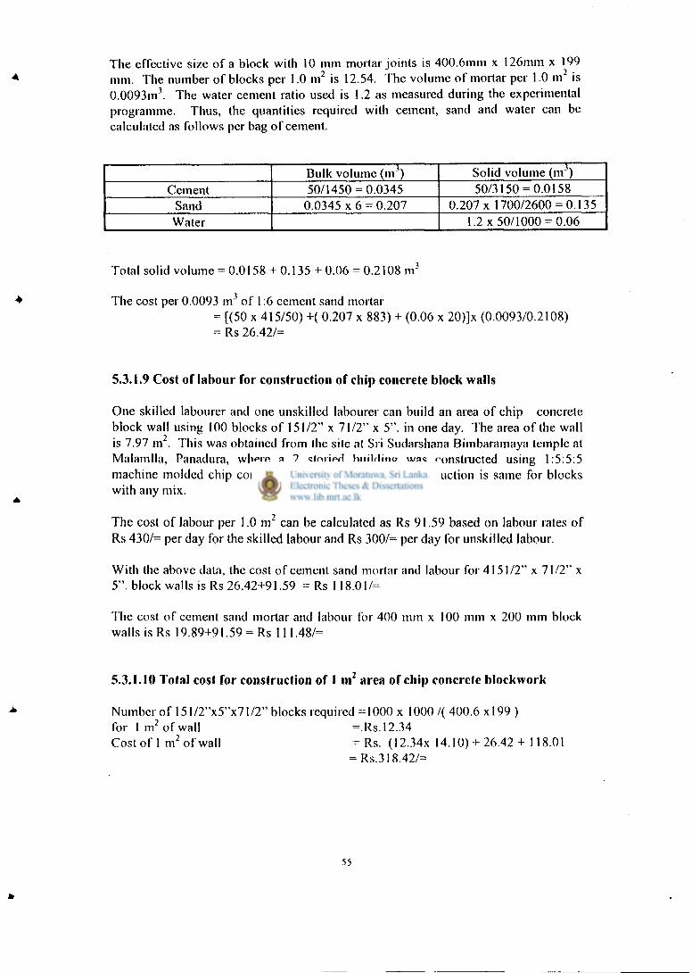
The effective size of a block with 10 mm mortar joints is 400.6mm x 126mm x 199 mm. The number of blocks per 1.0 m 2 is 12.54. The volume of mortar per 1.0 m 2 is 0.0093m3. The water cement ratio used is 1.2 as measured during the experimental programme. Thus, the quantities required with cement, sand and water can be calculated as follows per bag of cement.
Bulk volume (m 3) Solid volume (m 3) Cement 50/1450 = 0.0345 50/3150 = 0.0158
Sand 0.0345 x 6 = 0.207 0.207 x 1700/2600 = 0.135 Water 1.2 x 50/1000 = 0.06
Total solid volume = 0.0158 + 0.135 + 0.06 = 0.2108 m 3
The cost per 0.0093 m 3 of 1:6 cement sand mortar = [(50 x 415/50) +( 0.207 x 883) + (0.06 x 20)]x (0.0093/0.2108) = Rs 26.42/=
5.3.1.9 Cost of labour for construction of chip concrete block walls
One skilled labourer and one unskilled labourer can build an area of chip concrete block wall using 100 blocks of 151/2" x 71/2" x 5". in one day. The area of the wall i s 7.97 m'. This was obtained from the site at Sri Sudarshana Bimbaramaya temple al Malamlla, Panadura, where a 2 storied building was constructed using 1:5:5:5 machine molded chip concrete blocks. This rate of construction is same for blocks with any mix.
The cost of labour per 1.0 m 2 can be calculated as Rs 91.59 based on labour rates of Rs 430/= per day for the skilled labour and Rs 300/= per day for unskilled labour.
With the above data, the cost of cement sand mortar and labour for 4151/2" x 71/2" x 5". block walls is Rs 26.42+91.59 = Rs 118.01/=
The cost of cement sand mortar and labour for 400 mm x 100 mm x 200 mm block walls is Rs 19.89+91.59 = Rs 111.48/=
5.3.1.10 Total cost for construction of 1 m 2 area of chip concrete blockwork
Number of 151/2"x5"x71/2" blocks required =1000 x 1000 /( 400.6 x l99 ) for I m 2 of wall =.Rs. 12.34 Cost of 1 m 2 of wall = Rs. (I2.34x 14.10) + 26.42 + 118.01
= Rs.318.42/=
55

The cost of 1 m 2 of 400 mm. x 100 mm. x 200 mm. MMCC block wall with different mixes are given in Table 5.6
Table 5.6: Cost of 1 m 2 of 400 mm. x 100 mm. x 200 mm. MMCC block wall with different mixes
Cost of Cost of Total blocks labour and Cost
Mix (Rs.) mortar (Rs.) (Rs.)
1:5:5:5 152.07 111.48 263.55 1:4:3:10 146.62 111.48 253.10 1:4:3:12 144.18 111.48 255.66 1:4:4:14 142.45 111.48 253.93
5.3.2 Cost of brick walls
Since the bricks are of non-standard size, the material requirements given in Building Schedule of Rates cannot be used directly. Thus, material quantities are calculated using solid and bulk densities.
5.3.2.1 Cost of 210 mm thick brick walls
When bricks of 200 mm in length, 100 mm in width and 50 mm height are used, the effective height of a brick wil l be equal to 60 mm. Thus, the number of courses per 1 m height is 1000/60 = 16.67. The number of bricks per stretcher course is 2 x 1000/210 = 9.52. The number of bricks for the header course is 1000/110 = 9.09.
The volume of mortar in a stretcher brick is (210 x 105 x 60 - 200 x 100 x 50)x I0~9 = 0.000323 m \
The volume of mortar in a header brick is (210 x 110 x 60 - 200 x 100 x 50) x 10 9 = 0.000386m3.
The total volume of mortar for 1 m 2 of brickwork = (8.67 x 9.52 x 0.000323 + 8 x 9.09 x 0.000386) = 0.0593m3
The number of bricks for 1 m 2 of brickwork with 5% wastage, as allowed in Building Schedule of Rates for breakage
= (8.67 x 9.52 + 8 x 9.09) x 1.05= 163.01 bricks
The cost of bricks is Rs 3000.00/= for 1000 bricks, inclusive of transport and handling costs according lo the Building Schedule rates approved by the Western Provincial Council. For the calculations, a cost of Rs 3/= per brick was used. Thus, the cost for 163.01 bricks is Rs 489.03.
56

Cost of mortar is calculated by using the values in section 5.3.1.8.1
Cost of mortar = (20.17/0.007) x 0.0593 = Rs 170.96
Work norms as given in Building Schedule of Rates (BSR) adopted by Buildings Department states thai one square of brickwork; up lo l s l floor level needs 2.25 days mason and 3.75 days labourer. Labour cost for I square of brickwork = 2.25 x 430 + 3.75 x 300
= lis 2092.50 Labour cosl for 1 m 2 of brickwork = {2092.50 /(100/3.282)}
= Rs 225.12 Total cost of brickwork for 1.0 m 2 = Rs 489.03 + 170.96 + 225.12
= Rs 885.1 I
5.3.2.2 Cosl of 110 mm thick brick walls
When bricks of 200 mm in length, 100 mm in width and 50 mm height are used, the effective height of brick wi l l be equal to 60 mm. Thus, the number of courses per 1 in height is 1000/60 = 16.67. Number of bricks for a length of 1000 mm is 1000/210 = 4.76. Al l the bricks wil l be used as stretcher bricks.
The volume of mortar in a stretcher brick is (210 x I 10 x 60 - 200 x 100 x 50)x 10''' = 0.0004m3.
The total volume of mortar for l m 2 of brickwork = (16.67 x 4.76 x 0.0004) = 0.031 7 m 3
The number of bricks for I m 2 of brickwork with 5% wastage as allowed in Building Schedule of Rates
= (16.67 x 4.76) x 1.05 = 83.31 bricks
As per section 5.3.2.1,
Cost of bricks al Rs 3.00/= per unit = Rs 249.93
Cosl of mortar is calculated by using the values in section 5.3.1.8.1
Cosl of mortar =(20.17/007) x 0.0317 = Rs 91.34
Work norms as given in Building Schedule of Rates (BSR) adopted by Buildings Department states that one square of brickwork; up lo I s ' floor level needs 1.5 days mason and 2.0 days labourer.
Labour cosl for I square of brickwork = 1.5 x 430 + 2 x 300 = Rs 1245
Labour cosl for 1 m 2 of brickwork = {1245)/(100/3.282)} = Rs 133.94
Total cosl of brickwork for 1.0 m2 = Rs 249.93 + 91.34 + 133.9 = Rs 475.51
57
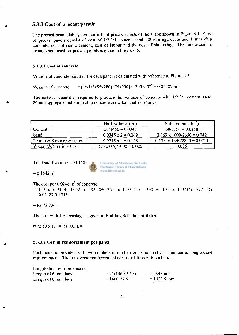
5.3.3 Cost of precast panels
The precast beam slab system consists of precast panels of the shape shown in Figure 4.1. Cost of precast panels consist of cost of 1:2:3:1 cement, sand, 20 mm aggregate and 8 mm chip concrete, cost of reinforcement, cost of labour and the cost of shuttering. The reinforcement arrangement used for precast panels is given in Figure 4.6.
5.3.3.1 Cost of concrete
Volume of concrete required for each panel is calculated with reference to Figure 4.2.
Volume of concrete = {(2xl/2x55x280)+75x900}x 300 x A)"9 = 0.02487 nr
The material quantities required to produce this volume of concrete with 1:2:3:1 cement, sand, 20 mm aggregate and 8 mm chip concrete are calculated as follows.
Bulk volume (m 1) Solid volume (in"') Cement 50/1450 = 0.0345 50/3150 = 0.0158 Sand 0.0345 x 2 = 0.069 0.069 x 1600/2650 = 0.042 20 mm & 8 mm aggregates 0.0345 x 4 = 0.138 0.138 x 1440/2800 = 0.0714 Water (W/C ratio = 0.5) (50 x0.5)/1000 = 0.025 0.025
Total solid volume = 0.0158 + 0.042+ 0.0714+ 0.025
= 0.1542nr
The cost per 0.0288 nr of concrete = (50 x 6.90 + 0.042 x 682.50+ 0.75 x 0.0714 x 1190 + 0.25 x 0.0714x 792.10)x
0.02487/0.1542
= Rs 72.83/=
The cost with 10% wastage as given in Building Schedule of Rates
= 72.83 x 1.1 = Rs 80.11/=
5.3.3.2 Cost of reinforcement per panel
Each panel is provided with two numbers 6 mm bars and one number 8 mm. bar as longitudinal reinforcement. The transverse reinforcement consist of lOos of 6mm bars
Longitudinal reinforcements, Length of 6 mm. bars = 2/(1460-37.5) = 2845mm. Length of 8 mm. bars = 1460-37.5 = 1422.5 mm.
5 8

Transverse reinforcement, Length of 6 mm. bars = 10 (300-50) = 2500 mm. Total length of 6 mm. bar =2845+2500 = 5345mm. Cost of reinforcement with 10% wastage
= (1.4225x1.1x0.395x66.40)+(5.345 x 1.1 x 0.222 x 66.40) = Rs. 127.70/=
5.3.3.3 Cost of formwork
It is preferable to have five sets of reusable formwork in order to ensure continuous construction. The formwork can be easily removed two hours after casting a panel. These five sets of formwork wil l need about 2.4 m 2 of timber of 20 mm thickness which can be considered at Rs 325/= per m 2 for non-durable timber species such as Rubber, Mango etc.
A caipcnter and a helper can make five sets in one day. The carpenter is paid at Rs 430/= and the helper at Rs 300/= per day. An additional cost of Rs 250/= is allocated for five formwork sets to meet the cost of nails, mould oil etc. It is also assumed that the formwork sets wil l be used for an area of 1000 square feet, which means a total of 200 panels wil l be cast.
The total cost for five formwork sets = Rs 25x30 + 300 + 4300 + 250 = Rs 1730/=
The formwork cost per panel = 1730/200 = Rs 8.65/=
5.3.3.4 Cost of labour
Two unskilled labourers, who are given sufficient training in the casting of panels, would be able to make ten panels per day according to the work study carried out at Sudarshna Bimbaiamaya temple at Malamulla site. Thus, the cost per panel with unskilled labourers being paid at Rs 300/= per day is Rs (300 x 2)/10 = Rs 60/=.
5.3.3.5 Total cost per panel
The total cost per panel should include the cost of concrete, cost of mild steel, cost of formwork and cost of labour.
Total cost per panel = Rs 80.11 + 127.70+8.65+60.00= Rs 276.46/=
5.3.4 Cost of precast beams The total cost of precast beams consist of cost of 1:2:4 cement, sand, 20 mm aggregate concrete, cost of reinforcement, cost of labour and the cost of shuttering. The reinforcement arrangement used for a precast beam is given in Figure A. 12
59

5.3.4.1 Cost of concrete
Volume of concrete required for each beam of cross section 200 mm deep x 125 mm wide x 3600 mm long = 0.15 x 0.2 x 3.6 = 0.108 m\
The material quantities required to produce this volume of concrete with 1:2:4 cement, sand, 20 mm aggregate concrete are calculated as follows.
Bulk volume (nr') Solid volume (m 3) Cement 50/1450 = 0.0345 50/3150 = 0.0158 Sand 0.0345 x 2 = 0.069 0.069 x 1600/2650 = 0.042 20 mm aggregates 0.0345 x 4 = 0.138 0.138 x 1440/2800=0.0714 Water (W/C ratio = 0.5) (50 x0.5)/1000 = 0.025 0.025
Total solid volume = 0.0158 + 0.042 + 0.0714+ 0.025 = 0.1542 nr
The cost per 0.09 nr of concrete required per beam
= (50 x 6.90 + 0.042x 682.50+ 0.0714 x 1190 + 0.025 x 20) x 0.108 / 0.1542 =Rs 321.22
5.3.4.2 Cost of reinforcement per beam
Each beam is provided with two 12 mm tor steel bars of length 3.6 m each as longitudinal reinforcement at bottom. The reinforcement requirement for shear links and the two 6 mm mild steel bars provided as top reinforcement in the precast beam to resist handling stresses is of length 12.81 m..
Length of 12 mm. diameter bars = 2x3.6 = 7.2 m. Length of 6mm diameter bars =2x3.6 = 7.2 m. Length o of 6mm diameter stirrups =21x0.610 = 12.81m. Total length of 6mm. diameter bars = 7.2 + 12.81 = 20.01 m.
Allow 10% wastage.
Cost of reinforcement =(20.01 x 0.222 x 66.40 x 1.1) + (7.2 x 1.1 x 0.617x66.40) = Rs.648.93/=
5.3.4.3 Cost of formwork
Reinforced concrete beams can be precast on cement rendered area using only the side shutters. The area of formwork required is (3.6 + 0.15) x 0.2 x 2 = 1.5m2. Formwork timber cost is calculated at Rs 325/= per m 2. A carpenter and a helper would have to work less than half a day to make a set of formwork. The carpenter is paid at Rs 430/= and the helper at Rs 300= per day. It is assumed that this fornrwork set can be used for casting 8 beams.
Allow 10% wastage.
6 0

The cost o r beam formwork = Rs 1.5x325 x 1.1 +(430+ 300)0.5 = Rs.758.25/=
The formwork cost per beam is calculated by considering that the total cost of formwork is Rs 758.25.This can be used 8 times.
Cost of formwork per beam = Rs. 94.78/=
5.3.4.4 Cost of labour
One skilled labourer and one unskilled labourer can cast one beam per day attending to tasks like preparation of reinforcement, mixing of concrete, placing of concrete etc. Thus, the cost per beam with the skilled labourer being paid at Rs 430/= per d ay and the unskilled labourers being paid at Rs 300/= per day is Rs 430+300 = Rs 730/=
5.3.4.5 Total cost per beam
The total cost per beam should include the cost of concrete, cost of tor steel, cost of mild steel, cost of formwork and cost of labour.
Total cost per beam = Rs 321.22 +648.93+ 94.78+ 730
= Rs 1794.93/=
5.3.5 Cost of the composite slab
The cost of composite slab includes the cost of precast beams and slab panels, cost for placing precast elements and laying the insitu concrete.
5.3.5.1 Cost of labour for the composite slab
The casting of composite slab of the building constructed at Sri Sudarshna Bimbaramaya temple required one skilled labourer and five unskilled labourers for placing the precast beams and slab panels and laying of the insitu cast concrete for an area of 3.6 m x 4.5 m.
The cost of labour for an area of 3.6 m x 4.5 m in Building I
= 430 x 1 +300 x 5 = Rs. 1930/=
The cost of labour required for an area of 3.6 m.x 6.0 m. is interpolaed and the labour cost is Rs. 2573.33 in Building 2
61
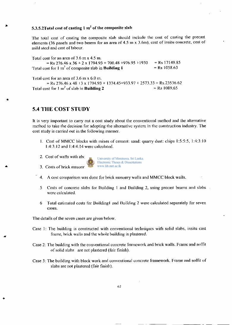
5.3.5.2Total cost of casting 1 in 2 of the composite slab
The total cost of casting the composite slab should include the cost of casting the precast elements (36 panels and two beams for an area of 4.5 m x 3.6m), cost of insitu concrete, cost of mild steel and cost of labour.
Total cost for an area of 3.6 m x 4.5 m. = Rs 276.46 x 36 + 2 x 1794.93 + 700.48 +976.95 +1930 = Rs 17149.85
Total cost for 1 m 2 of composite slab in Building 1 = Rs 1058.63
Total cost for an area of 3.6 m x 6.0 m. = Rs 276.46 x 48 +3 x 1794.93 + 1374.45+933.97 + 2573.33 = Rs.23536.62
Total cost for 1 m 2 of slab in Building 2 = Rs 1089.65
5.4 THE COST STUDY
It is very important to carry out a cost study about the conventional method and the alternative method to take the decision for adopting the alternative system in the construction industry. The cost study is carried out in the following manner.
1. Cost of MMCC blocks with mixes of cement: sand: quarry dust: chips 1:5:5:5, 1:4:3:10 1:4:3:12 and 1:4:4:14 were calculated.
2. Cost of walls with above MMCC blocks were calculated.
3. Costs of brick masonry walls were calculated.
4. A cost comparison was done for brick masonry walls and MMCC block walls.
5 Costs of concrete slabs for Building 1 and Building 2, using precast beams and slabs were calculated.
6 Total estimated costs for Buildingl and Building 2 were calculated separately for seven cases.
The details of the seven cases are given below.
Case 1: The building is constructed with conventional techniques with solid slabs, insitu cast frame, brick walls and the whole building is plastered.
Case 2: The building with the conventional concrete framework and brick walls. Frame and soffit of solid slabs are not plastered (fair finish).
Case 3: The building with block work and conventional concrete framework. Frame and soffit of slabs are not plastered (fair finish).
62
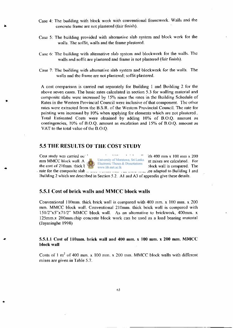
Case 4: The building with block work with conventional framework. Walls and the concrete frame are not plastered (fair finish).
Case 5: The building provided with alternative slab system and block work for the walls. The soffit, walls and the frame plastered.
Case 6: The building with alternative slab system and blockwork for the walls. The walls and soffit are plastered and frame is not plastered (fair finish).
Case 7: The building with alternative slab system and blockwork for the walls. The walls and the frame are not plastered; soffit plastered.
A cost comparison is carried out separately for Building 1 and Building 2 for the above seven cases. The basic rates calculated in section 5.3 for walling material and composite slabs were increased by 15% since the rales in the Building Schedule of Rates in the Western Provincial Council were inclusive of that component. The other rates were extracted from the B.S.R. of the Western Provincial Council. The rate for painting was increased by 10% when applying for elements which are not plastered.. Total Estimated Costs were obtained by adding 10% of B.O.Q. amount as contingencies, 10% of B.O.Q. amount as escalation and 15% of B.O.Q. amount as VAT to the total value of the B.O.Q.
5.5 THE RESULTS OF THE COST STUDY
Cost study was carried out by comparing 110mm brick wall with 400 mm x 100 mm x 200 mm MMCC block wall. Also cost of M M C C walls with different mixes are calculated. For the cost of 210mm. thick brick wall, 151/2"x5"x71/2" M M C C block wall is compared. The rate for the composite slab is also worked out. All these rates are adapted to Building 1 and Building 2 which are described in Section 5.2. A l and A3 of appendix give these details.
5.5.1 Cost of brick walls and MMCC block walls
Conventional 110mm. thick brick wall is compared with 400 mm. x 100 mm. x 200 mm. MMCC block wall. Conventional 210mm. thick brick wall is compared with 151/2"x5"x71/2" MMCC block wall. As an alternative to brickwork, 400mm. x 125mm.x 200mm.chip concrete block work can be used as a load bearing material (Jayasinghe 1998)
5.5.1.1 Cost of 110mm. brick wall and 400 mm. x 100 mm. x 200 mm. MMCC block wall
Costs of 1 m 2 of 400 mm. x 100 mm. x 200 mm. MMCC block walls with different mixes are given in Table 5.7.
63

Table 5.7: Cost of 1 m 2 of 400 mm. x 100 mm. x 200 mm. MMCC block wall with different mixes
Cost of Cost of Total blocks labour and Cost
Mix (Rs.) mortar (Rs.) (Rs.)
1:5:5:5 152.07 111.48 263.55 1:4:3:10 146.62 111.48 258.18 1:4:3:12 144.18 111.48 255.66 1:4:4:14 142.45 111.48 253.98
Cost of 1.0 m 2 of 110mm. thick brickwall = Rs 479.51 /=
5.5.1.2 Cost of 210mm. thick brickwall and 151/2"x5"x71/2" MMCC block wall
Cost of 1 m 2 of I51 /2 "X5"X71 /2 " MMCC block wall = Rs. 318.42 Cost of 1.0 m 2 of 210mm. thick brickwall = Rs 885.11
5.5.2 Costs of buildings used for the case study
Bill of Quantities are prepared for Building 1 and Building 2 and the rates are adopted as described in Section 5.4. A l and A3 of appendix give these details. A3 and A4 of the appendix give the costs of different trades separately and the B.O.Q. amounts and total estimated costs of Building 1 and Building 2 respectively.
5.5.2.1 Total amount of Bill of Quantities and the Total Estimated Costs of Building I
The B.O.Q for the Building 1 for the above seven cases are shown in B l of the Appendix. B2 of the appendix shows the total figures of each trade and the estimates for all the seven cases of Building 1 and these figures are shown in Table 5.8.
Table 5.8 Costs for seven cases analyzed on Building 1
Case N o 1 2 3 4 5 6 7
B.O.Q.amount in 000' 14260 13820 12951 12760 12842 12528 12036
Total Estimated Cost in 000'
19252 18657 17484 17227 17337 16913 16249
Rate/sq.m.(Rs) 12379 11996 11242 11077 11147 10875 10448

5.5.2.2 Total amount of Bill of Quantities and the Total Estimated Costs of Building2
The B.O.Q for the Building 2 for the above seven cases are shown in B3of the Appendix. B4 of the appendix shows the total figures of each trade and the estimates for all the seven cases of Building 2 and these figures are shown in Table 5.9.
Table 5.9 Costs for seven cases analyzed on Building 2
Case No 1 2 3 4 5 6 7
B.O.Q.amount in 000'
14299 13790 12981 12,812, 13166 12858 12450
Total Estimated Cost in 000'
19303 18617 17525 17296 17775 17358 16807
Rate/sq.m.(Rs) 12412 11971 11268 11121 11429 11161 10807
5.6 ANALYSIS ON COST STUDY
The analysis is carried out in the following manner.
1. A comparison for the rates of brick walls and MMCC block walls is carried out.
2. A comparison of total amount of concrete work for solid slab system and composite slab system is done separately for Buildingl and Building 2. Further analysis is carried out to find out the saving with respect to the overall cost of building.
3. The above comparison is done for different combinations of walls and slabs of Building l and Building 2 which consists of seven types of combinations sa described in Section 5.4.
5.6.1 Comparison of brick walls with M M C C block walls
The basic rates worked out in Section 5.3.1 and 5.3.2 for MMCC block walls and brick walls are analysed as below.
5.6.1.1 Comparison of 110mm. thick brick wall with 400mmxl00mmx200mm MMCC block wall
Cost of 1.0 m 2 of I 10mm. thick brickwall = Rs 475.51 Cost of 1.0 m 2 of 1:5:5:5 MMCC block wall =Rs. 263.55 % Saving = 475.5l-263.55x 100
475.51 =44.57 %
65

Cost of MMCC block walls with different mixes are compared with brick wall and the % savings for different mixes are given in Table 5.10.
Table 5.10 Cost of 1 m 2 of 400 mm. x 100 mm. x 200 mm. MMCC block wall with different mixes and % savings
Mix Total Cost
(Rs.) % saving
1:5:5:5 263.55 44.57 1:4:3:10 258.18 45.76 1:4:3:12 255.66 46.23 1:4:4:14 253.93 46.59
5.6.1.2 Comparison of 210inm. thick brick wall with 151/2"x5"x71/2" MMCC block wall
Cost of 1 m 2 of 15l/2"x5"x71/2" MMCC block wall = Rs. 318.42 Cost of 1.0 m 2 of 210mm. thick brickwall = Rs 885.11 % saving w.r.t. brick work = 885.11-318.42 x 100
885.11 = 64.02%
5.6.2 Analysis of cost study for solid slab system and composite slab system for Building 1 and Building 2
Bl of the Appendix provides the B.O.Q. for Building 1 for all the seven cases explained in Section 5.4. 132 of the Appendix shows the summary sheet for Building 1 giving total costs for each trade separately for all these cases. Similarly, B3 and B4 of the Appendix give details for Building 2 for all the seven cases.
By comparing the costs of concrete works, the % saving that could be gained by adopting the composite slab system can be obtained for each building.
As per the summary sheet B2 of the Appendix for Building!,
The total cost of concrete work with solid slab system = Rs. 4,832,638.49
The total cost of concrete work with composite slab system = Rs. 4,110,500.46
Saving for the concrete work of Building 1 = Rs. 4,832,638.49 - 4,1 10,500.46 = Rs. 722,138.03
% of the saving w. r. t. solid slab = 722,138.03 x 100 4832638.49
= 14.94%
6 6

% of the saving w. r. t. overall cost
Saving for the concrete work of Building 2
% of the saving
% of the saving w. r. t. overall cost
= 722138.03 x 100 14260000
= 5.06%
= Rs. 4,802,803.21 -4,325,722.15 = Rs.477081.06
= 477081.06 x 100 4802803.21
= 9.93 %
= 477081.06 x 100 19303000
= 2.47 %
Building 1 and Building 2 are of same length and same width but with different grid intervals. Building 1 has the grid intervals 4.5 m. spacing whereas the Building 2 has the grids at 6.0 m. intervals. The above calculations show that the savings are more when grid intervals are at closer spacing.
5.6.2.1 Comparison of overall costs of Building I and Building 2
The B.O.Q. amounts and the total estimated costs of Building I and Building 2 are given in Table 5.8 and Table 5.9 respectively for all cases considered.
The % saving for all cases are worked out with respect to case 1 of both buildings.
% saving for Building 1 for case 2 = 14260000-13820000 x 100 14260000
=3.09% % savings of total costs of Building 1 and Building 2 for all seven cases are given in Table 5.11.
Table 5.11; % saving of total costs of Building 1 and Building 2 for all seven cases
Case No 1 2 3 4 5 6 7
% saving in Building I
- 3.09 9.18 10.52 9.95 12.15 15.60
% saving in Building 2
- 3.55 9.21 10.40 7.92 10.08 12.93
The first four cases are associated with the conventional slab system of building; where as the other cases are associated with the alternative slab system of building. It can be seen that the % variations are almost same for both buildings with conventional slab system despite of their grid spacing.
But with alternative slab systems, the % variation for different cases is in the range of 2.03 %-2.67 %. Since the perimeters of Building 1 and Building 2 are same, the cost
67

of alternative wall ing material does not contribute to this effect. Therefore, it is clear that the costs o f alternative slab system with pre cast beams and slabs has the effect on savings of buildings and the savings are more when the grid intervals are closer.
5.6.2.2 Comparison of seven cases considered for Building 1 and Building 2
Cost analysis was carried out for different cases to study the effect o f using alternative systems for both Bui ldingl and Building 2. Table 5.12 gives the details considered for different cases o f Building 1 and Building 2. The % savings given in the Table 5.12 were the average values for Building 1 and Building 2, which were shown in Table 5.11.
Table 5.12: Details o f cases with average saving percentages
Case No
Type of material Plastered / Not plastered Saving %
Case No
Walls Slab Walls Slab Frame
Saving %
1 Brick in situ concrete plastered plastered plastered -
2 Brick in situ concrete plastered not plastered not plastered 3.32
3 Block in situ concrete plastered not plastered not plastered 9.20
4 Block in situ concrete not plastered plastered not plastered 10.46 5 Block precast slab-beam plastered plastered plastered 8.94 6 Block precast slab-beam plastered plastered not plastered 11.12 7 Block precast slab-beam not plastered plastered not plastered 14.27
Table 5.12 shows the saving percentages that can be obtained by not plastering walls and frame o f the buildings. However, the soffit o f the slab with precast beams and panels has to be plastered.
The rate per sq. m. is compared for Building 1 and Building 2 for all cases is shown in Table 5.12. By comparing the B.O.Q. amount or total estimated cost or square meter rate, the % saving receives for any case is same.
The maximum % saving can be obtained from case 7 for both buildings. In this case the building is provided with M M C C block walls and precast slab beam system. The walls and the frame are not plastered, but the soffit is plastered. The % saving for Building 1 and Building 2 are 15.60% and 12.93% respectively. This indicates that it is not possible to get a substantial cost reduction due to the adoption o f the above strategies. This is because the cost o f structure and plastering is about 40% o f the overall cost. However, the strategies presented are extremely pertinent in the present day context since the steel prices have increased substantially along with severe restrictions on sand supply.
68

The total costs presented in Table 5.8 and Table 5.9 indicates that the adoption o f proposed strategies can result in significant savings in the project costs. This could make the projects financially more attractive. The costs that can be used for financial calculations also can vary between Rupees 10450/= to 12400/= per sq.m. Thus, the adoption o f alternative strategies can provide a larger building when the budget is already fixed which may have more benefits to the occupants. Alternatively, a project with alternative building materials may be more attractive when a higher number of projects can be competed for limited amount o f funding
5.7 CONCLUSIONS
The escalating costs of traditional building materials are increasing the cost of construction at a rapid rate, which may make some building projects not viable in financial terms. One solution to this is the adoption o f alternative building materials that can provide adequate structural performance and durability.
It is shown that the adoption o f alternative wall ing materials w i l l not need much deviation since the presently adopted design philosophy uses an unbraced frame for carrying most of the lateral and vertical loads. The same approach makes the adoption o f the precast beam slab system also straightforward. This is an encouraging finding for the designers who contemplate the use o f these alternatives in future.
The detailed cost study carried out for a typical office building has indicated that the cost o f structural members can be reduced by about 9.93% - 14.94% from the conventional solid slab construction depending upon the grid spacing... When the savings possible with plastering are considered with machine moulded blocks, the overall cost o f the building can be reduced by about 9.2% as shown in Table 5.12. Therefore, there is a strong reason to pursue further research and development in the adoption o f alternative building materials even for large projects in order to make building projects more attractive in financial terms.
The use o f lesser amount o f cement has a benefit in environmental terms. Cement in considered as responsible for 5% o f the green-house gas emission in the world. Thus, every attempt to minimize this essential ingredient in future building projects wi l l have substantial benefits in term of minimizing the global warming.
5.7.1 Conclusions on machine moulded chip concrete blocks
Chip concrete blocks can be produced either as hand molded (hand molded chip concrete - HMCC) or with machines (machine moulded chip concrete blocks - MMCC) . For large projects, machine moulded chip concrete blocks would be ideal due to the quantities
6 9

required. Chip concrete block differ from the generally manufactured cement sand blocks with the use o f 6-8 mm chips. This allows the use o f mixes such as 1:7:12 or 1:8:I4 with cement: sand: chips. Thus cement to aggregate ratio is 1:19 or 1:22, respectively. It is much higher than 1:10 ratio usually recommended for cement sand blocks. Laboratory experiments carried out under this project have indicated strength in excess o f 1.2 N/mm 2
recommended in SLS 855 . In Sri Lanka, these blocks manufactured in machines are provided with a plaster. However, the accurate dimensions o f these blocks provide an ideal opportunity to construct the walls with greater care so that a pleasing finish can be given without the plastering. This is one o f the options that should be actively pursued for future building projects.
5.7.2 Conclusions on precast reinforced concrete beam slab system
Traditional insitu cast reinforced concrete solid slabs generally used in buildings have certain disadvantages as listed below:
1. In lightly loaded reinforced concrete slabs having low spans, the reinforcement requirement is generally governed by serviceability requirement such as crack controlling, not by flexural requirements. Hence, the usage of reinforcement is not optimum. Since, considerable slab thicknesses are required for controlling the deflections, concrete usage is also not optimum. These can contribute to cost increases and, thus, the cost of reinforced concrete floor slabs is considered as a major cost item.
2. The concrete below the neutral axis serves only the putpose of providing durability to reinforcement while adding to the dead weight.
3. The insitu cast concrete slabs need falsework and formwork which has no significant use after the construction of the slab.
4. Construction of insitu cast floor slabs is a lime consuming process and this activity generally lies on the critical path of construction. Hence, it wil l determine the total construction duration of buildings.
Thus, it is necessary to find an alternative slab system that optimises the use of concrete and reinforcement, and also to minimize the use of formwork Any reduction in the time of construction is also very important. In order to overcome above drawbacks, at least to some extent, a precast reinforced concrete composite beam slab system can be introduced. It has the following advantages:
1 Since reinforced concrete is used for producing the precast slab panels, precasting operation can be successfully carried out even with unskilled labourers after giving them some training.
2 The precast beams are located at 1.5 m spacing. Thus, the span of precast slab panels is 1.5 m. This helps to reduce the flexural reinforcement requirement in the precast slab panels.
70
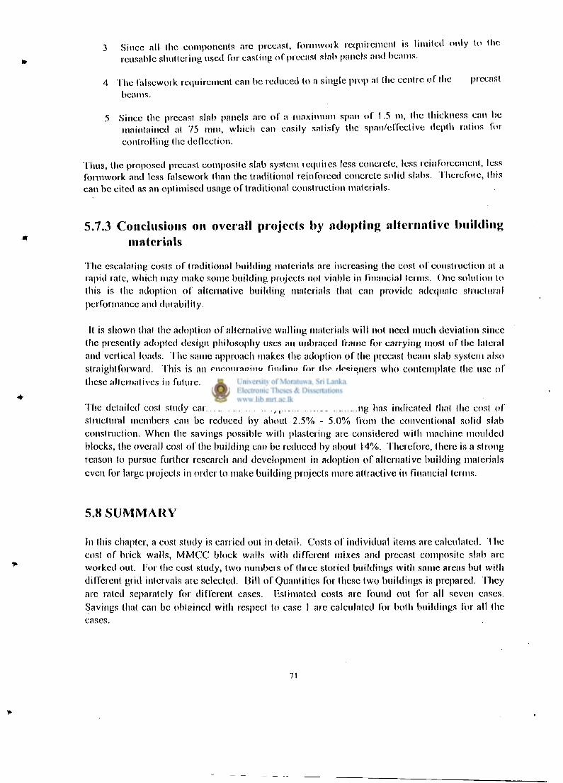
3 Since all (lie components arc precast, formwork requirement is limited only to tlic reusable shuttering used for casting of precast slab panels and beams.
4 The falsework requirement can be reduced to a single prop at the centre oT the precast beams.
5 Since the precast slab panels arc of a maximum span of 1.5 m, the thickness can be maintained at 7 5 mm, which can easily satisfy the span/effective depth ratios for controlling the deflection.
Thus, the proposed precast composite slab system requires less concrete, less reinforcement, less formwork and less falsework than the traditional reinforced concrete solid slabs. Therefore, this can be cited as an optimised usage of traditional construction materials.
5.7.3 Conclusions on overall projects by adopting alternative building materials
The escalating costs of traditional building materials are increasing the cost of construction al a rapid rate, which may make some building projects not viable in financial terms. One solution to this is the adoption of alternative building materials that can provide adequate structural performance and durability.
It is shown thai the adoption of alternative walling materials wil l not need much deviation since (he presently adopted design philosophy uses an unbraced frame for carrying most of the lateral and vertical loads. The same approach makes the adoption of (he precast beam slab system also straightforward. This is an encouraging finding for the designers who contemplate (he use of these alternatives in future.
The detailed cost study carried out for a typical office building has indicated that the cost of structural members can be reduced by about 2 . 5 % - 5 . 0 % from the conventional solid slab construction. When the savings possible with plastering are considered with machine moulded blocks, the overall cost of the building can be reduced by about 14%. Therefore, there is a strong reason to pursue further research and development in adoption of alternative building materials even for large projects in order to make building projects more attractive in financial terms.
5.8 SUMMARY
In this chapter, a cost study is carried out in detail. Costs of individual items are calculated. The cost of brick walls, MMCC block walls with different mixes and precast composite slab arc worked out. For the cost study, two numbers of three storied buildings with same areas but with different grid intervals are selected. Dill of Quantities for these two buildings is prepared. They arc rated separately for different cases. Estimated costs are found out for all seven cases. Savings thai can be obtained with respect to case I are calculated for both buildings for all the cases.
71

Chapter 6
C O N C L U S I O N S A N D F U T U R E W O R K
6.1 General
The cost o f construction is one o f the key factors that can influence the decision making about the adoption o f alternative building materials. For this, a cost study is carried out by adopting the alternative wall ing materials and slab systems to a typical three storey office building. The building is of length 28.8 m and a width o f 18.0 m. It is not provided with any internal partition walls. In order to determine the effect o f the grid spacing on the cost wi th alternative materials, two grid arrangements were selected in one direction. It is a grid spacing o f 4.5m.x 4 (Building 1) and 6.0 m. x 3 (Building 2) for the side with a width o f 18 in. In the other direction, 8 bays were selected wi th a spacing o f 3.6 m. The details o f the cost study are shown in chapter 5.
When performing cost studies for the use in project evaluation purposes, there are two different cost components, namely the actual cost and the cost that includes the provision for contingencies (10%), escalation (10%) and V A T (15%). This means that the actual cost on Bi l l o f Quantities wi l l be enhanced by about 35% to determine the projected cost o f the building. Therefore, any reduction in the actual cost o f the building can make a project proposal much more attractive at the project appraisal stages. In this study, attention was focused on both these. The escalating costs o f traditional building materials are increasing the cost o f construction at a rapid rate which may make some building projects not viable in financial terms. One solution to this is the adoption o f alternative building materials that can provide adequate structural performance and durability at a lower cost. It is shown that the adoption o f alternative wall ing materials w i l l not need much deviation since the presently adopted design philosophy uses an unbraced frame for carrying most o f the lateral and vertical loads. The same approach makes the adoption o f the precast beam slab system also straightforward. This is an encouraging f inding for the designers who contemplate the use o f these alternatives in future.
The detailed cost study carried out for a typical office building has indicated that the cost o f structural members can be reduced by about 2.5%-5% from the conventional solid slab construction. When the savings possible with plastering are considered with machine moulded blocks, the overall cost o f the building can be reduced by about 14%. Therefore, there is a strong reason to pursue further research and development in the adoption o f alternative building materials even for large projects in order to make building projects more attractive in financial terms.
72

6.2 FUTURE WORK
In this research study, attention was focused on the alternative materials that can be used for loadbearing walls and floor slabs o f multistorey buildings. It may be possible to find alternative roof systems such as those using optimised steel designs to replace the traditional timber framework since timber has become a depleting source.
Another area that can be useful is the performance o f alternative surface coatings and plasters that can be used with cement stabilised soil blocks and chip concrete blocks. A successful development o f such water repellent coatings would enable the use o f cement stabilised soil blocks with more confidence even at locations where there is a risk o f occasional floods.
It would be useful to assess the performance o f cement stabilised soil blocks as a loadbearing material at locations where foundations are liable to undergo differential settlements such as clayey soils. The development o f cost effective strong foundation systems could also be useful.
For the composite slab system, the use o f economical non structural screeds such as 1:3:3 cement, sand and 8 mm chips could be beneficial with respect to stiffening the slab. A detailed study into the feasibility o f using these screeds properly could be beneficial since this stiffening can be used to improve the dynamic characteristics o f the composite slab, in addition to reducing deflections associated with heavy loads.
I f cement stabilised soil blocks are manufactured as commercial ventures, it may be appropriate to carry out detailed environmental impact assessment so that adequate measures could be taken to minimise the damage to environment.
When alternative building materials and methods are introduced, it w i l l be important to determine the strategies that can be adopted for popularising such techniques so that the majority o f the population could enjoy any benefits.
73

REFERENCES
Auram Press 3000 manual (undated), Production and use of compressed earth blocks, CRATerre-EAG, Aurovi l le building centre, India, 141 p.
Bryan, A. J. (1988 a), "Criteria for the suitability o f soil for cement stabilisation", Building and Envionment, Vo l . 23, No. 4 , pp 309-320.
Bryan, A. J. (1988 b), "Soil/cement as a wall ing materal - 1, Stress/strain properties" Building and Environment, Vo l . 23, No. 4, pp 321-330.
Bryan, A. J. (1988 c), "Soi l / cement as a wall ing material - 2, Some measures o f durabil ity", Building and Environment, Vo l . 23, No. 4 , pp 331-336.
BS 12 : 1978, British Standard Specification for ordinary and rapid hardening port land cement, B.S.I., London.
BS 1377 : 1975, Methods oftest for soil for civil engineering purposes, B. S. I., London.
BS 5628 : 1978: Part 1, Code of practice for structural use of masonry - Unreinforced masonry, B.S.I., London.
BS 6399 : Part 1 : 1984, Code ofpractice for dead and imposed loads, B.S.I., London.
BS 8110 : Part 1 : 1985, British Standard for Structural Use of Concrete, B.S.I., London.
BS 8110 : Part 2 : 1985, British Standard for Structural Use of Concrete, B.S.I., London.
Building Regulations (1985), City of Colombo Development Plan, Volume I I , Colombo Municipal Council, 74 p.
Building Shedule o f Rates, Department o f Buildings, Ministry o f Housing and Construction, Sri Lanka.
Chandrakeerthy, S. R. De S. (1987), "Influence o f some current brick laying practices on structural behaviour o f br ickwork", Engineer, pp 90 - 102.
Chandrakeerthy, S. R. De S. (1991 a), "Control o f rain penetration o f masonry with special reference to Sri Lankan conditions", Engineer, March, pp 29-38.
Chandrakeerthy, S. R. De S. (1991 b), "Detail ing and other important considerations o f blockwork", Engineer, September, pp 3-19.
74

Crowley, M.H. "Portland cement: The construction industries .greenhouse gas problem " in CIB 2003 International Conference on Smart and sustainable built environment Nov. 19-21, 2003. Brisbane, Australia.
Guillaud H. , Jeffroy T. & Odul P., (1995), Compressed earth blocks, Vol . 2 , CRATcrre-EAG, The international centre for earth construction, France, 148 p.
Hendry, A. W., Sinha, B. P., Davies, S. R. (1981), An introduction to loadbearing design, Ellis Horwood, England, 184 p.
Jamal, S. Q., Sheikh, A. S. (1987), "The use and performance o f soil stabilised building blocks in flood affected rural areas, Proceedings, Building materials for low-income housing,Tha\\and, January, E & F.N. Spon, pp 302 - 309.
Jayasinghe C. , Perera A.A.D.A.J. "Alternative concrete floor slab system for residential buildings", Engineer , Journal of Institution of Engineers, Sri lanka, Vo l xxx i i i , No 2 September 2000 pp 54-65. (2000 a)
Jayasinghe C . , Perera A.A.D.A.J. An alternative Concrete Floor Slab System for Residential Buildings pp 54 -65 Journal Engineer. Septwember 2000
Jayasinghe C , (1999) Alternative Building Materials for Sri Lanka, PhD. Thesis, Department o f Civi l Engineering, University o f Moratuwa. ( 2000 b)
Jayasinghe C , Perera A.A.D.A.J. Load testing on a reinforced precst slab system for Residential Buildings Transactions (2000) pp96-106
Jayasinghe C , Studies on Load Bearing Characteristics o f Cement Stabilised Soil Blocks Transactions (1999) pp 63-72
Jayasinghe, M. T. R (1997), Loadbearing brickwork construction for Sri Lanka, Strad Consultants, Sri Lanka, 141 p.
Jayasinghe M. T. R. (1998), "Loadbearing construction with local bricks", Engineer, Journal o f IESL, Vol . xxv i i , No. 1, pp 49-57.
Jayasinghe, M. T. R., Maharachchi, D. P. K. (1998), "Use o f reinforced brickwork for crack freeloadbearing construction", Proc. Research for Industry - 1998, University o f Moratuwa, Sri Lanka, November, pp 38-51.
Jayasinghe, M. T. R (2002), Suitability of hand moulded chip concrete blocks for single storey houses Engineer, Journal o f IESL, September pp 24-30.
75

Kulasinghe, A. N. S. (1998), "Bui ld ing research and development", Newsletter o f National Bui lding Research Organisation o f Sri Lanka, March/June, Vo l . 8, Number 1-2, pp 1-4.
Lahlauh E. A. & Waldron P., (1992), "Memebrane action in one way slab strips", Proceedings of Institution of Civil Engineers, Structures and Buildings, 94, Nov. pp 419-428.
McHendry, P. G., May, G. W. (1984), Adobe and rammed earth buildings, A Wiley Interscience Publications, New York, 217 p.
Moss R. M., (1993), "Load testing o f beams and block concrete floors", Proceedings of Institute Civil Engineers, Structures and Buildings, 99, May, pp 211-223.
Moss R. M. (1994), "Assessment o f stiffness increase due to non-structural screeds", The Structural Engineer, Vol . 72, No. 14, July, pp 221-228.
Perera A. A. D. A. J., (1992), "Lessons from used low cost housing methods", Transactions - Institute of Engineers, Sri Lanka, pp 128-132.
Perera A. A. D. A. J., (1993), Landcrete blocks, Research Monograph, Department o f Civ i l Engineering, University o f Moratuwa, 16 p.
Perera, A. A. D. A. J. (1994), "Cement stabilised soil block houses", Trasactions -Institution of Engineers, pp 115 - 128.
Perera, A. A. D. A. J. & Jayasinghe, C. (1995), Introduction of compressed soil blocks to Sri Lanka, Research Report, Department o f Civ i l Engineering, University o f Moratuwa, 116 p.
Ranasinghe, M. (1997), "Clay miniming for building materials: Future land use", Engineer, Vo l . X X V I , December, pp 42-49.
Reddy, B. V. , Jagadish , J. S. (1989), "Properties o f soil - cement block masonry", Masonry International, Vo l . 3, No. 2, October pp 80-84.
Reddy, B. V. (1995), "Wal ls using stabilised mud blocks", Proceedings, Building construction for district primary education programme of West Bangalore, Salt Lake City, India. Jayasinghe C. , Perera A.A.D.A.J.
Saxton, R. H. (1995), "The performance o f cob as a building material", The Structural Engineer, Vo l . 73, No. 7, pp 111 -115
SLS 855:Part I: 1989, Specification for Cement Blocks- Requirements, SLSI, 19p.
76

SLS 855: Part 2: 1989, Specification for Cement Blocks- Test Methods SLSI, 12pp-16pp
Smith B. S. & Coull A., (1991), Tall building structures, Jon Wiley, New York, p 537.
Taranath, B. S. (1988), Strucutural analysis and design of tall buildings, McGraw Hi l l , New York, 739 p
Thorburn, S (1997), "The challenges o f structural engineering : safety with economy and harmony", The Structural Engineer, Vo l . 75, No. 20, pp 349-354.
Vembersky, J. N. J. A. (1994), "Precast concrete in buildings today and in the future", The Structural Engineer, Vo l . 72, No. 15, Aug, pp 237-242.
Wil l iams, M. S., Waldron, P. (1994), "Evaluation o f methods o f predicting occupant induced vibrations in concrete floors", The Structural Engineer, Vo l . 72, No. 20, pp 334-340.
77

APPENDIX A
A.l Design of precast concrete reinforced concrete slab
A.2 DESIGN OF COMPOSITE PRECAST BEAM SLAB SYSTEM
Design o f composite precast beam slab system was clone for two buildings with grid intervals at 3.6m.and 4.5m. in one bui lding and grid intervals at 3.6m.and 6.0m.intervals in the other building. The length and the width o f the two buildings are same. Both o f them are three storied buildings and the length and the width are 28.8m. and 18.0m. They are named as Bui lding I and Bui lding 2.
In both o f these buildings,3.6m. long precast beams and 300mm. wide precast slabs are selected for the design o f precast beam slab system.
I i " e
G
E •o B
OO
e
G
E •o B
OO
e
G
E •o B
OO
E OO
,
B
E
B
OO
,
, ,
B
E
B
OO
4.5m | 4.5m | 4.5m j <l.5in
I 8 .0m
Figure A.l Plan of the Building 1 with grid intervals at 3.6 in. and 4.5 in. intervals

3.6m
3.
6m
3.6m
3.
6m
E OO OO
3.6m
E OO OO
3.6m
3.
6m
3.6m
6 . 0 m 6 . 0 m 6 . 0 m
18.0m
6 . 0 m
Figure A.2 Plan of the Building 2 with grid intervals at 3.6 m. and 6.0 m. intervals
The fol lowing design data has been used for the structural design o f composite reinforced concrete precast beam slab system.
Density o f concrete = 24 kN /m 3
Weight o f finishes = 0.5 kN /m 2 (assuming 20 mm thick cement rendering) Weight o f partitions (movable) = 1.0 kN /m 2
Imposed load = 2.7 kN o f concentrated load or 2.5 kN /m 2 o f uniformly distributed load Construction load = 0.9 kN o f concentrated load Cover to reinforcement = 25 mm (BS 8110) Reinforcement used = 6 mm diameter Grade 250 mi ld steel bars
A.3 The design of precast concrete slabs
A slab panel o f length 1500mm, width 300 mm and o f dimensions shown in Figure.A.3 was used for the calculations. These slab panels can be supported either by load bearing walls or reinforced concrete beams o f suitable cross section. An end bearing o f 40 mm was used with the slab panels.
79
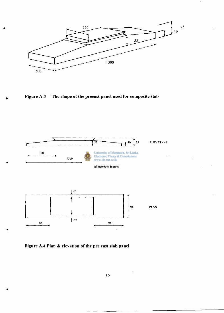
Figure A.3 The shape of the precast panel used for composite slab
r " 5 5 ~ 75 ELEVATION
300 300
1500
(dimensions in mm)
300 PLAN
Figure A.4 Plan & elevation of the pre cast slab panel
80

The slab is designed for the fol lowing load cases.
1. Slab subjected to a uniformly distributed imposed load o f 2.5 kN/m with an allowance o f 0.5 kN /m 2 for finishes and 1.0 kN /m 2 for movable partitions.
2. Slab subjected to a concentrated imposed load o f 2.7 kN acting at the centre with an allowance o f 0.5 k N / m 2 for finishes and 1.0 k N / m 2 for movable partitions.
3. Precast slab subjected to a concentrated load of 0.9 kN acting at the centre during the construction.
A.3.1.1 Design for a uniformly distributed load
The precast panels w i l l form a continuous floor slab once connected with insitu cast concrete. Thus, each panel can be subjected to a uniformly distributed imposed load o f 3.5 k N / m 2
Design for flexure
Dead load = 0.3 x 0.075x 24 = 0.54 kN / m
Superimposed dead load = 0.5 x 0.3 = 0.15 kN/m
Imposed load = 3.5 kN /m 2
Design bending moment at mid span
= 1.4 x (0.54 + 0.15) x 1.462/8 +{ 1.6 x (3.5x 0.3) x 1.462/8} = 0.71 kNm
The quantity o f reinforcement is calculated as specified in CI 3.4.4.4 o f BS 8110: Part 1: 1985
Effective depth = 75 -25 -3 = 47 mm
K= M/bd 2 f c u = 0.71 x 10 6 / 300 x 47 2 x 20 = 0.053< 0.156
Z = d{0.5 + (0.25 - K/0.9) , / 2 } = 0.948 d < 0.95 d
A s = M/ 0.87 f y Z = 0.7lx 106 / 0.87 x 250 x 0.948 x 47 = 73.26 m m 2
Three 6 mm diameter mi ld steel bars are sufficient. However, two 6mm diameter & one 8 mm. diameter mild steel bars wi l l be used.
81

Design for shear
Design shear force = 1.4 (0.54 + 0.15) x 1.46/2 +(1.6 x 4.5 x 0.3) x 1.46/2 = 2.28kN
Design shear stress = v = 2.28x10 3 /(300 x 47) = 0.162 (Table 3.9 )
100 Ag/byd = 100 x 108.9/(300 x 47) = 0.352<3
400/d = 400/47 = 8.51
v c = 0.79(0.758) l / 3 (8.51) l / 4 / l .25 = 0.983
v < v c
Hence satisfactory.
Determination of bearing width
It is necessary to check whether a bearing width o f 40 mm would be sufficient for the precast panels.
Net bearing width required is given in CI 5.2.3.2 o f BS 8110: Part l:1985as the design ultimate support reaction per member divided by the product o f design effective bearing length and ultimate bearing stress. The design ultimate support reaction is 2.28 kN as calculated above. The bearing length per panel is 300 mm and the ultimate bearing stress is 0.4 x f c u. Thus, the bearing width required can be calculated as follows.
Net bearing width = 2.28x 10³/(300 x 0.4 x 20) = 0.95 mm
Thus, a bearing width o f 40 mm should be provided (CI 5.2.3.2 o f BS 8110/1).
A.3.1.2 Design for a concentrated load
The magnitude o f the concentrated load that acts as an imposed load at the centre o f a precast panel is 2.7 kN. When this load acts on the panel, load sharing between adjacent panels should be available since the panels are connected with insitu concrete. However, the precast panel is designed for a ful l load o f 2.7 kN ignoring any reduction in the load due to load sharing.
Dead load = 0.3 x 0.075 x 24 = 0.54 kN / m
Superimposed dead load = 0.5 x 0.3 = 0.15 kN/m
82

Design bending moment with concentrated load assuming that one panel resists the total load
= {1.4 x (0.54 + 0.15) x 1.462/8} + {1.6 x 2.7 x 1.46/4} = 1.82 kNm
Effective depth = 75 -25 -3 = 47 mm
K = M / b d 2 f c u = 1.82 x 10 6 / 300 x 47 2 x 20 = 0.14 < 0.156
Z = d{ 0.5 + ( 0.25 - K/0.9) , / 2 } = 0.807 d (CI 3.4.4.4, BS 8110/1)
A s = M/0.87f y Z = 1.82 x 10 6 /(0.87 x 250 x 0.807 x 47) = 220 m m 2
Number o f 6 mm diameter bars required = 7.7
It should be noted that there would be load sharing to a certain extent between precast panels once those are connected with insitu cast concrete. Since the aim was to verify whether BS 8110: Part 1: 1985 could be used for the design o f precast panels for construction and service loads, lesser amount o f reinforcement than required for this case was provided. The reinforcement provided is 2 Nos, 6 mm diameter and one number o f 8 mm. diameter mi ld steel bars. In Section A.3.1.4, it is shown that this amount o f reinforcement is satisfactory with load sharing.
A s provided = 2x28.3 + 50.3 = 106.9 m m 2
This quantity has to be checked with the minimum amount o f reinforcement.
100 A s / bh = 0.475% > 0.24% (C1.3.12.6, BS 8110/1)
Hence satisfactory.
Design for shear
In order to determine the design shear force, the concentrated load o f 2.7 kN should be located very close to the face o f the support. Thus, the shear force due to the point load is taken as 2.7 kN for the calculations.
Design shear force = 1.4 (0.54 + 0.15) x 1.46/2 +(1.6 x 2.7/2) = 2.64 kN
Design shear stress = 2.64 x 10³ /(300 x 47) = 0.187kN/m 2
100 A s /b v d = 100 x 106.8/(300 x 47) = 0.758 <3
83

v c = 0.790.758 l / 3(400/47) l / 4 /1.25 = 0.983
v c = 0.983 N/mm 2 > 0.352N/mm 2 (Table 3.10, BS 8110/1)
Hence satisfactory.
Check for deflection
The precast panel o f depth 75 mm should be checked for serviceability l imit state o f deflection.
Modification factor for tension reinforcement = 2.0 (Table 3.11, BS 8110/1)
Allowable span / effective depth ratio = 40
Actual span / effective depth ratio = 1460/47 = 31.06
Hence satisfactory.
Distribution reinforcement in transverse direction
A s = 0.24 x 1448 x75/ 100 = 260.64 m m 2 = 9.2 bars
Hence provide 6 mm bars at 150 mm centers. This marginally violates the maximum clear spacing of reinforcement given by the 3 x effective depth rule which gives a value o f 141 mm. The actual clear spacing is 144 mm.
A.3.1.3 Design for construction loads
During construction there w i l l not be any load sharing. The superimposed dead load also wi l l not be acting on the slab. The dead load is varying along the length o f the slab, but it is assumed as a weight equivalent to a concrete thickness o f 75 mm. A construction load o f 0.9 kN acting at the centre o f the precast panel is considered since there is hardly any space on a panel o f width 300 mm x length 1500mm to have more than one worker occupying it at the centre. In BS 6399: Part 1: 1984, it is stated that for roofs and ceilings with access, a concentrated load o f 0.9 kN should be considered for design purposes.
Basic span / effective depth = 20 (CI. 3.4.6.3, BS 8110/1)
100 A s / b h = 0.24 (CI 3.12.5.3, BS 8110/1)
84

Flexural design at mid section for construction loads
Design bending moment
= 1.4 x 0.54 x 1.462/8 + 1.6 x 0.9 x 1.46 IA = 0.201+ 0.525= 0.726 kNm
Since the shape shown in Figure A.3 was used, the width o f the compression area during construction is 250 mm
K = M/bd 2 f c u = 0.726 x 10 6 / 250 x 47 2 x 20 = 0.065 < 0.156
Z = d { 0.5+ ( 0.25- K/0.9)" 2 } = 0.921 d < 0.95 d
A s = M/ 0.87 f y Z = 0.726 x 10 6 / (0.87 x 250 x 0.921 x 47) = 77.1 m m 2
The number o f 6 mm diameter bars required is 2.72. Therefore, the steel provided is sufficient.
Flexural design at other critical sections
Since the thickness of the section is varying at the tapered portion o f the precast slab panel, the flexural reinforcement required is calculated at another section, which has a possibility to govern longitudinal reinforcement requirement.
c:
280 mm
55 mm
1180 mm
Figure A. 5 Dimensions of other critical sections for flexure in precast panel
85
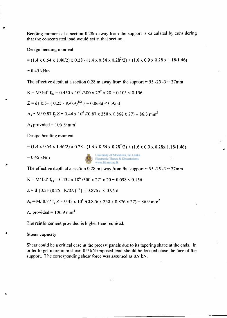
Bending moment at a section 0.28m away from the support is calculated by considering that the concentrated load would act at that section.
Design bending moment
= (1.4 x 0.54 x 1.46/2) x 0.28 - (1.4 x 0.54 x 0.28 2/2) + (1.6 x 0.9 x 0.28 x 1.18/1.46)
= 0.45 kNm
The effective depth at a section 0.28 m away from the support = 55 -25 -3 = 27mm
K = M/ bd 2 f c u = 0.450 x 10 6 /300 x 27 2 x 20 = 0.103 < 0.156
Z = d{ 0.5+ ( 0.25 - K/0.9) l / 2 } = 0.868d < 0.95 d
A s = M/ 0.87 f y Z = 0.44 x 10 6 /(0.87 x 250 x 0.868 x 27) = 86.3 m m 2
A s provided = 106 .9 m m 2
Design bending moment
= (1.4 x 0.54 x 1.46/2) x 0.28 - (1.4 x 0.54 x 0.28 2/2) + (1.6 x 0.9 x 0.28x 1.18/1.46)
= 0.45 kNm
The effective depth at a section 0.28 m away from the support = 55 -25 -3 = 27mm
K = M7 bd 2 f c u = 0.432 x 10 6 /300 x 27 2 x 20 = 0.098 < 0.156
Z = d {0.5+ (0.25 - K/0.9) l / 2 } = 0.876 d < 0.95 d
A s = M/ 0.87 f y Z = 0.45 x 10A /(0.876 x 250 x 0.876 x 27) = 86.9 m m 2
A s provided = 106.9 m m 2
The reinforcement provided is higher than required.
Shear capacity
Shear could be a critical case in the precast panels due to its tapering shape at the ends. In order to get maximum shear, 0.9 kN imposed load should be located close the face o f the support. The corresponding shear force was assumed as 0.9 kN .
86

Design shear force = ( 1.4 x 0.54 x 1.46/2 + 1.6 x 0.9 ) = 1.99 kN
Depth at support critical section taken as the face o f the support as shown in Figure A.6 = {(55 - 40V300} x 40 + 40 = 42 mm
4 0 m m
Figure A. 6 Critical section for shear in precast panels
The effective depth = 42 - 25 - 6/2 = 14 mm
Design shear stress = 1.99 x 10 3 / (300x 14.0) = 0.47 N/mm 2 (CI 3.4.5.2, BS 8110/1)
100 A s / b v d = 100 x 84.9/ (300 x 14.0) = 2.02 (Table 3.9, BS 8110/1)
v c = 1.08 N/mm 2 > 0.47N/mm 2
Hence satisfactory.
A.3.1.4 Check for a concentrated load with load sharing
It is shown that when the precast panels are connected with insitu concrete to form a slab, a maximum o f 66.67% o f a concentrated load acting on a precast panel would be carried by it. due to load sharing. The remaining portion w i l l be carried by the panels on either side. (Jayasingha C, 1999).
87

Dead load = 0.3 x 0.075x 24 = 0.54 kN / m Superimposed dead load = 0.5 x 0.3 = 0.15 kN/m Imposed load = 2.7 kN Design bending moment at mid span
= 1.4 x (0.54 + 0.15) x 1.462/8 + { 1.6 x 2.7 x 0.667 x 1.46/4} =0.802 kNm
The quantity o f reinforcement is calculated as specified in CI 3.4.4.4 o f BS 8110: Part 1: 1997 Effective depth = 75 -25 -3 = 47 mm
K= M/bd 2 f c u = 0.802 x 10 6 / 300 x 47 2 x 20 = 0.06 < 0.156
Z = d{0.5 + (0.25 - K/0.9) l / 2 } = 0.928 d < 0.95 d
A s = M/ 0.87 f y Z = 0.802 x 10 6 / 0.87 x 250 x 0.928 x 47 =77.42 m m 2
The steel area provided was 106.9 m m 2
Shear and deflection was satisfactory even without load sharing. Hence, those were not checked with load sharing being effective.
A. 3.1.5 Reinforcement arrangement for precast slab panels
The reinforcement arrangement shown in Figure A.7 was selected for precast panels on the basis o f the design calculations presented above.
R 6
R 6 ( ^ 1 5 0 c/c
^ i i
1500inm
& '-1
Figure A.7 Reinforcement details for the precast slab panels
88

A.3.2 The design of the composite beam
The composite beam consists o f a precast beam provided with an insitu cast concrete flange. Hence, it should be designed for loads at service and those occur during construction.
For the design o f composite beam for loads at service, the flange action provided only by the insitu cast concrete is considered. The composite beam used for the structural design is shown in Figure A.8. The dead load on the beam is calculated assuming that the precast slabs are simply supported. The length o f the beam was selected as 3.6 m in order to support slab panels.
670mm
200 mm
150mm
Figure A.8 Composite flanged beam used for design calculation
The composite slab is designed for the fol lowing loads. The dead load consists o f weight o f precast slab panels, precast beam and insitu cast concrete. The slab is represented by a thickness o f 75 mm. The beam is represented by a section o f 150 mm in width x 200 mm in depth.
The superimposed dead load due to finishes = 0.5 k N / m 2
The imposed load = 3.5 k N / m 2
Since the beam is designed as a flanged beam, the effective flange width should be calculated. The length o f the beam is considered as 3600 mm.
Effective flange width = 3600/5 + 150 = 870 mm (CI 3.4.1.5 o f BS 8110/1) The actual width = 670mm
Design dead load = 1.4 (0.150 x 0.20 x 24 + 0.075 x 1.5 x 24) + 1.4 x 0.5 x 1.5 = 5.83 kN/m
Design imposed load = 1.6 x 3.5 x 1.5= 8.4 kN/m Design bending moment = 5.83 x 3.62/8 + 8.4 x 3.62/8 =23.05 kNm
89

Effective depth = 275-25 - 6 - (12/2) = 238 mm
K = M/ bd 2 f c u = 23.05 x 10 f7 (670x 238 2 x 20)
= 0.03 < 0.156
Z = d{ 0.5+ ( 0.25- K/0.9)" 2 } = 0.96d > 0.95 d
Z = 0.95 d should be used for the calculations.
Z = d- x/2; thus the depth to the neutral axis, x, used for calculations = 0.1 d = 23.8 mm
Actual depth to the neutral axis = (1 - 0.96) x 2 x d = 0.08 d = 19.04 mm
A s = M / 0.87 f y Z = 23.05 x 10 6 /(0.87 x 460 x 0.95 x 238) = 254.7 m m 2
A s provided = 3,12 mm diameter bars = 339 m m 2
Design for shear
Design shear force = 5.83 x 3.6/2 + 8.4 x 3.6/2 = 25.61 kN
Design shear stress (v) = 25.61 x 10³/150 x 238 = 0.0.717 N/mm 2 (Ci 3.4.5.2, BS 8110/1)
1 0 0 A s / b d = 100x 339/(150x 238) = 0.94
400/d = 400/238 = 1.68
v c = 0.717(0.94) , / 3 ( l .68) l / 4 /1.25 = 0.64
0.5 v c < v < v c+0.4
0.32 < 0.717 < I .04
Provide minimum links
A s v = 0.4 b v S v /0.87f y v = 0.4 x 150 x S v /(0.87 x 250)
S v = 28.3 x 2 x 0.87 x 250/(0.4 x 150) = 205 mm c/c
0.75 d = 0.75 x 238 = 179.5 mm
Provide 6 mm diameter links at 175 mm c/c.
90

Horizontal shear due to design ultimate load
At the interface o f the precast and in situ components, the horizontal shear force due to design ultimate loads has to be checked (CI 5.4.7.1 o f BS 8110: Part 1: 1985). In this case, the interface is in tension zone since the actual depth to the neutral axis is only 15.25 mm. The horizontal shear force due to design ultimate loads is the compression calculated from the ultimate bending moment. This can be taken as 0.4 f c u x breadth o f the compression flange x depth to the neutral axis.
Design horizontal shear force = 0.4 x 20 x 670 x 19.04 x 10 3 =102.05 kN
The contact width for the precast and insitu interface is 75 mm since the beam width is 150mm and the bearing width for each precast slab panel is 40 mm (150 - 2 x 40 = 75 mm). The average horizontal design shear stress is calculated by dividing the design horizontal shear force by the area given by mult iplying the contact width by the beam length between the point o f maximum moment and the point o f zero moment.
The average horizontal design shear stress = (102.05 x 10 3)/(70 x 3600/2) = 0.81 N/mm 2
The average design shear stress should then be distributed in proportion to the vertical design shear force diagram to give the horizontal shear at any point along the length o f the member. Since the shear stress distribution is triangular, the design shear stress, at the end o f the beam can be calculated as follows.
The maximum horizontal design shear stress = 0.81 x 2 = 1.62 N/mm 2
The allowable design ultimate horizontal shear stress at interface is 1.2 N /mm 2 for grade 25 concrete as indicated in Table 5.5 o f BS 8110/1. The maximum horizontal design shear stress exceeds this value and hence all the horizontal shear force should be carried on reinforcement anchored either side o f the interface (CI 5.4.7.4 o f BS 8110/1). The amount o f steed required in mm 2 /m is given by
AS= 1000 x 70x1.62 0.87x 250
A s = 421.37 mm 2 .
Since each 6 mm diameter l ink has two legs, the area o f reinforcement per l ink is 2 x 28.8 = 56.6 mm 2 . Thus, the link spacing required is 1000/(421 / 56.6 ) = 134.4 mm c/c.
This can be satisfied by providing 6 mm links at 125 mm c/c. It should be noted that the links provided should be o f triangular shape with the top portion projecting out o f the precast beam so that it can be embedded in the insitu cast concrete.
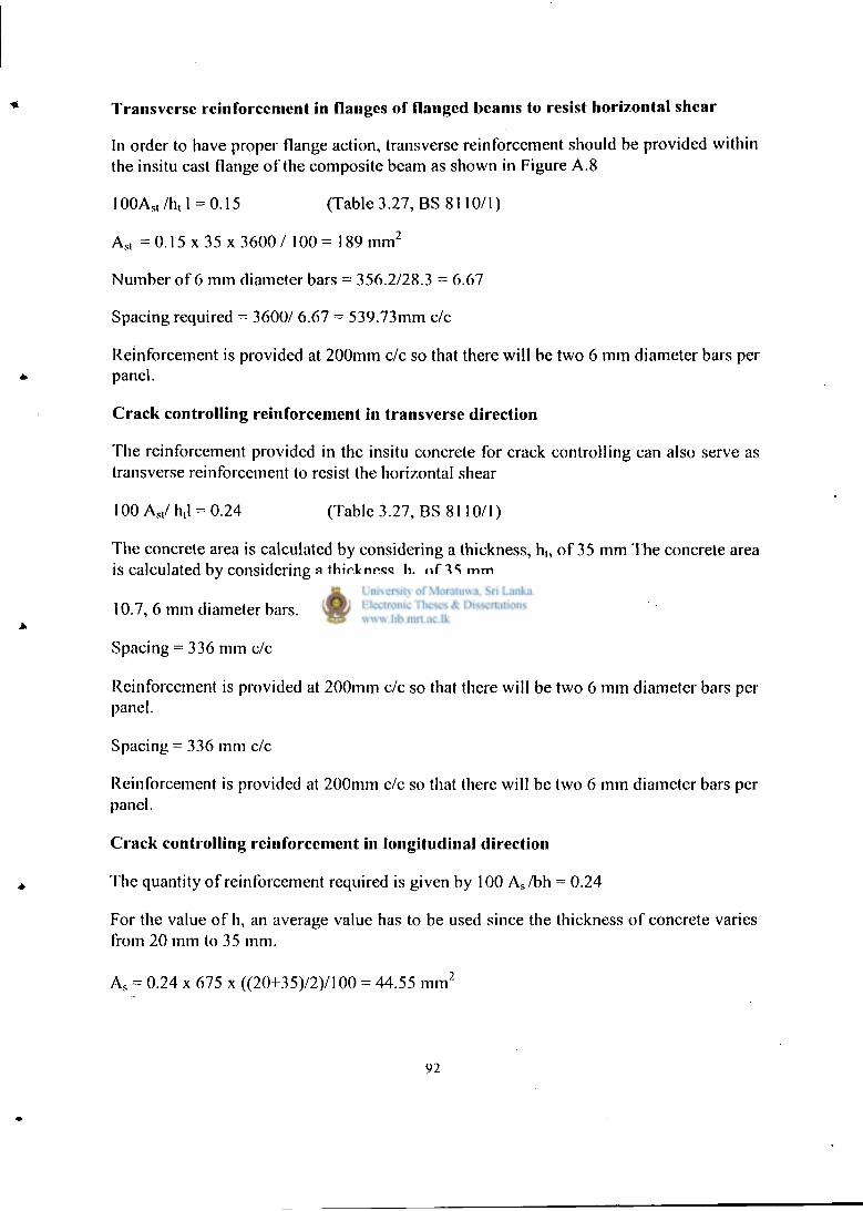
Transverse reinforcement in flanges of flanged beams to resist horizontal shear
In order to have proper flange action, transverse reinforcement should be provided within the insitu cast flange o f the composite beam as shown in Figure A . 8
100As, /h, 1 = 0.15 (Table 3.27, BS 8110/1)
A s , =0.15 x 35 x 3 6 0 0 / 1 0 0 = 189 m m 2
Number o f 6 mm diameter bars = 356.2/28.3 = 6.67
Spacing required = 3600/ 6.67 = 539.73mm c/c
Reinforcement is provided at 200mm c/c so that there w i l l be two 6 mm diameter bars per panel.
Crack controlling reinforcement in transverse direction
The reinforcement provided in the insitu concrete for crack controll ing can also serve as transverse reinforcement to resist the horizontal shear
100 A s , / h,l = 0.24 (Table 3.27, BS 8110/1)
The concrete area is calculated by considering a thickness, h,, o f 35 mm The concrete area is calculated by considering a thickness, h,, o f 35 mm.
10.7, 6 mm diameter bars.
Spacing = 336 mm c/c
Reinforcement is provided at 200mm c/c so that there w i l l be two 6 mm diameter bars per panel.
Spacing = 336 mm c/c
Reinforcement is provided at 200mm c/c so that there wi l l be two 6 mm diameter bars per panel.
Crack controlling reinforcement in longitudinal direction
The quantity o f reinforcement required is given by 100 A s / b h = 0.24
For the value o f h, an average value has to be used since the thickness o f concrete varies from 20 mm to 35 mm.
A s = 0.24 x 675 x ((20+35)12)1100 = 44.55 m m 2
92

Two 6 mm. diameter bars are sufficient. But provide four bars considering additional safety.
Figure A.9 Arrangement of longitudinal and transverse crack controlling reinforcement within insitu cast concrete provided over the precast beam
Crack controlling reinforcement can be provided in the longitudinal direction when the slab panels are supported on walls. The area o f this reinforcement can be equal to the crack controll ing reinforcement specified in CI 3.12.5.3 o f BS 8110: Part 1: 1985, which is given by 100 A s /bh = 0.24
Since the thickness o f concrete is varying from 35 mm to 20 mm, an average value was used for the calculations.
As = 0.24 x 300 x [(20+35)/2] /100 = 19.8 m m 2
One 6 mm diameter bar is sufficient. But provide two considering additional safety. This reinforcement could also be useful in providing some connectivity to the precast slab panels.
Deflection
The deflection check is made for a beam with a flange o f width 675 mm.
b w / b = 150 / 675 = 0.225 < 0.3
Basic span / effective depth = 20 M/bd 2 = 23.05 x 10 6 / (675 x 263 2) = 0.602 fy = (5/8) x 460 x 235/339= 199 N/mm 2
93

Modification factor = 2.0 (Table 3.11, BS 8110/1)
Allowable span / effective depth = 40
Actual span / effective depth - 3600 / 238 = 15.1 < 40
Hence satisfactory.
Figure A. 10 Arrangement of crack contro l l ing reinforcement provided wi th in insitu cast concrete over a load bearing wal l
A.3.2.1 Design of precast beam for construction loads
The precast beam should be designed for lifting stresses that arise during erection of the beams and also for the dead and imposed loads that would act during the construction of the slab.
Design of the precast beam for l i f t ing stresses
The precast beam can be lilted either as A or B given in Figure A.l I. The usual way of lilting is B. I lowcvcr, if the precast beam is lifted as shown in A, still it should be able to withstand the bending moments due to self weight.
94

B
A I
150 mm
V < >
200 mm
< > 150 mm
Figure A. 11 Lifting arrangements that can be used with precast beam
Design self weight = 0.150 x 0.2 x 24 x 1.4 = 1.008 kN/m
Design bending moment = 1.008 x 3.6 2 /8 = 1.633 kNm
Effective depth = 150 - 25 - 6 - 12/2 = 113 mm
K = M / b d 2 f c u = 1.633 x I 0 6 / 2 0 0 x 1132 x 20 = 0.0319 < 0.156
Z = d { 0.5 + (0.25 - K/0.9) , / 2 } = 0.963 d
A s = M / 0 . 8 7 f y Z = 1.633 x 10 6 /(0.87 x 460 x 0.95 x 113) = 38.01 m m 2
The steel area provided is 339mm 2 .
A.3.2.2 Design of the precast beam for precast slab loads
Since it is diff icult to predict the construction load exactly, the fol lowing strategy was adopted. The beam was designed to carry the load o f precast slabs, insitu concrete and the weight o f three people, each with 0.6 kN , while being supported at a spacing o f 3.6 m. However, a prop is provided at the centre o f the beam during construction so that any extra loads due to construction can be taken without failure. Designing o f the beam considering the full span would ensure that the possibilities for failure are extremely remote even i f the prop is removed accidentally while erecting the slabs.
Design load (only dead) = 1.4 ( 0.150x 0.2 x 24 + 0.075 x 1.5 x 24) = 4.79 kN/m
A
A
200 mm
95

Design imposed load = 0.6 x 3 x 1.6 = 2.88 kN
Design bending moment = 4.79 x 3.6 2 /8 + 2.88 x 3.6 /4 = 10.34 kNm
Effective depth = 200 - 25 - 6 -12/2 = 163 mm
K = M / b d 2 f c u = 10.34 x 10 6 / 150x 163 2 x 20 = 0.129 < 0.156
Z = d {0.5 + (0.25 - K/0.9) l / 2 } = 0.826d
A s = M/ 0.87 f y Z = 10.34 x 10 6 /(0.87 x 460 x 0.95 x 163) = 166.85mm 2
Hence provide 2, 12 mm diameter bars.
spacer bars al 1.0 in intervals
10mm mild steel bars provided to resist handling stresses
200 mm
Figure A. 12 Reinforcement arrangement for the precast beam
96

Bi l l o f Q u a n t i t i e s f o r B u i l d i n g 1 A P P E N D I X B I
ITEM No.
Description (Building 1)
>> £v
ci l ;
~ I 1
E
1 - -z ~ £ « t i < * ~
W U £ -
T J 1
_ J £ ^
2 * * £ "~ S E -c = i •=
• I r i W £ K
< i
Sf~ « Z = € A Z z 1 « J n 1: « E* y E I S
e <
K e
<
•2 Z
K *-~ : c
< I" IT £ *. « « *"~
5 E c ~ Z Z < £ 1 c £ =-
s 2 i
£ i *e —
< -& £ m "
U -
A EXCAVATION AND E A R T H W O R K
A Q . j Allow for clearing site Item 1 50.000.00 50.000.00 50.000.00 50.000.00 50.000.00 1 50.000.00 50.000.00 50.000.00
A O : Coiumn pits nv 76 272.00 20.672.00 20.672.00 20.672.00 20.672.00 76 20.672.00 20.672.00 20.672.00
A 03 Wall foundation m' 19 272.00 5.168.00 5.168.00 5.168.00 5.168.00 19 5.168.00 5.168.00 5.168.00
A 04 Staircase foundation nv 0.9 272.00 244.80 244.80j 244.80J 244.80 0.9 244.80 244.80 244.80
Earth Work 1 1 1 I ' Fi l l ins : 1 1
A 05 Approved hard earth filiinp under floors m' 551.53 290.00 159.943.70 159.943.70j 159.943.70 159.943.70 551.53 159.943.70 159.943.701 159.943.70
Excavation & Earth Work to Summary 236.028 .50 236.028.50J 236.028.50 2 3 6 , 0 2 8 . 5 0 236.028 .50 236.028 .50 236.028.50
B CONCRETE W O R K | | 75mm. Thick lean cement concrete 1:3:6 (40mm) in the following.
B 0 1 Column footings m' 60.10 331.00 •9.893.10 19.893.10 19.893.10 19.893.10 60.10 19.893.10 19.893.10 19.893.10
BG2 Staircase foundation m' 1.15 331.00 380.65 380.65 380.65 380.65 1.15 380.65 380.65 380.65
B03 wall foundation m' 85.00 331.00 28.135.00 28.135.00 28.135.00 28.135.00 85.00 28.135.00 28.135.00 28.135.00
Reinforced cement concrete 1:2:4 (20mm) in the following.
g | Column footings nv' 16.71 5.691.00 95.096.61 95.096.61 95.096.61 95.096.61 16.71 95.096.61 95.096.61 95.096.61
B 0 5 Staircase foobngs nv 0.30 5.691.00 1.707.30 1.707.30 1.707.30 1.707.30 0.30 1.707.30 1.707.30 1.707.30
B 0 9 Beams nr 43.16 5.691.00 245.623.56 245.623.56 245.623.56 245.623.56 26.32 149.787.12 149.787.12 149.787.12
B 10 l i : .5mroThick floor slab. m" 518.00 662.00 342.916.00 342.916.00 342.916.00 342.916.00 0.00 0.00 0.00 0.00
B 11 125mm Thick floor slab. m" 0.00 716.00 0.00 0.00 0.00 0.00 0.00 0.00 0.00 0.00
B 12 Waist and steps in staircases. nv' 2.60 5.691.00 14.796.60 14.796.60 14.796.60 14.796.60 2.60 14.796.60 14.796.60 14.796.60
B 13 150mm. Thick landing slab in staircase. m" 7.20 860.00 6.192.00 6.192.00 6.192.00 6.192.00 7.20 6.192.00 6.192.00 6.192.00
B 14 Landing beam nv 0.40 '5.691.00 2-276.40 2.276.40 2.276.40 2.276.40 0.40 2.276.40 2.276.40 2.276.40

; _ e - FAR FC
—*
Item NO.
Description (Building 1.) | 1 | W —
" M t £ < | S *" Sr = f -
* f
1 I ~ =
f - § f & = = •= e s c £
c * s e —
<
fa.
> «.
n
< r XT. S fc, ffi
= r — ^ Z
" • 22 ^ ^ Z — < =
< I •
f - § f & = = •= e s c £
c * s e —
< < - " i I
B 1;
75mm Thick cetnen; concreir !: 2 1.2:5 (25mm) thici: iri ground floor siab bedding.
m" 51 £ . 0 0 352.00 1E2336 .00J 182336 .00 182336 . 0 0 1823 36.0 0 518 .00 182336 . 00 1 S2336.0C 182336.00
B 16 200mir. iascii m' 0 .0( ' 5.691.00 O.OOj 0 . 0 0 0 . 0 0 0 . 0 0 0.94 5349.54 5349.54 j 5349.54
j F i m i floor level to second floor level. 1 ! 1 1 I I 1 1 Reinfon-ed Cement Concrete 1:2:4 ( 2 0 M M ) I in tbe follfowing. • !
E l * Composite siab witn precas: slabs i : beams m* 0.00 '12154.00 0 . 0 0 0 . 00 O.OOj 0 . 0 0 518.40 650.073.60 650.075.60 650.073.60
B I f |! ! 2 . 5 m i T . Thick fioo- slab. tr. : 518 .00 6E2.00| 3522376.00 253376 . 00 2532376.00J 3532376.00 0 . 0 0 1 O.OOj 0 . 0 0 0 .00
E 19 |': 25imr, Tnick floor siac. IT:' 0.00 "38 .00 0 . 0 0 O.OOj 0 . 0 0 ! 0 .00! 0.00 j O.OOj 0 .00! 0 .00
B 20 ICoiumr, shaft nv 6.32 6.062.00 3 8 3 1 ; . 84 38311.84! 3E311.84J 38311.84J 6.32 | J
3 8 3 i i.84| 38311.84! 38311.84
B : I I Beams nY 15.62 6.062.00 94.68844 94.688.44j 94.688.44j 94.68844| 19.12 I 115.905.44j 115.905.44 i 15.905.44
[Staircase beair, nv 0 40 c.062.00 2.424.80 2.424.80j 2.424.80| 2.424.80 040 | 2.424.80! 2.424.80 2.424.80
j200mir. fasci* nr 0.00 6.062.00 0 . 0 0 o.oo; O.OOj 0 .00! 0.94 j 5.698.28 5.698238 5.69828
(Second flon- level to roof level j | j | i [ i | 1
IReiniorced Cemeni Concrete 1:2:4 ( 2 0 M M ) I | ! i lin the follfowins 1 i i 1
! B : 4 1 Column shaft nr' 6.32 6367 .00 4C.239.44j 402339.44! 402339.44 402339.44J 632 | 40339.44 40339.44 4033944
B25 | Staircase beam IT."' 0.40 6J6T.O0 2.546.80 2346.80| 2346.80J 2.546.80J 0.40 | 2.546.80J 2.546.80 2346.80
B 2 6 1 Roof Beams i
nr 6.95 63 67.00 44 .123.31! ]
44.123.31 44.122.31 44.123.311 I
6.95 | 44.125.31 44.123.31 44.12331
lUsing ordinary plywood of 15nux thick!
Ibeading as follows.
llipto first floor level | 1 | i I 1 I i B : T | Sides of column footings n r 21.60 245.00 5392.00J 52392.001 52392 .00 52392.00! 21.60 | 5392.00J 52392.00 5392 .00
B28 j Sides of coiumn shaft. n r —
1 8 8 . 0 0 693.00 I3C22 84 .00! 1
1302384.00 1302384.00 1302384.00 188 .00 | 130384.00J 130384 .00! 130384 .00
B29 j Sides of staircase foundation. nr i . 0 0 693.00 693. OOj 693 .00 693 .00J 693 .00 ' I i.00 j 693 .00 695 .00; 693.00
B3C | Sides of staircase shaft. n r 3.90 693.00J 2.702.70 2.702.70J 2.702.70J 2.702.70 3.90 j 2.702.70 2.702.70| 2.702.70
B31 JSOFFII of slab. •
m 460 .00 594.00 273J40.00J 2752340.00 273340.00J i
2732340.00 0 . 0 0 j 0 . 0 0 O.OOj 0 .00
B22 |Sides and soffit of beams. nr 176.00 813.00 143.088.00j 145.O88.O0j 143.088.00j 143.088.00l 142.20 | 115.608.60 115.608.60j 115.608.60
- B33 jSides and soffit of tie beams. m" 184.00 813.00 149.5S2.00j 149.592.00J 149.592 .00 149392 .00 184.00 1492592.00 149.592.00j 149392 .00
B34 jSides and soffit of staircase with landing. nr 25.69 594.00 14.071.86 14.071.86 14.071.86 14.071.86 25.69 14.07i.86 14.071.86 14.071.86
|F i r s i floor level to second floor level. | I 1 B 3 5 jSofii i of siab. m : 460.00 624.00| 287.040 .00 287.040.00 287.040 .00 287.040 .00 0 . 0 0 0 . 0 0 0 . 0 0 0 .00
g 3 ^ | Sides of coiumn shaft nr 1.00.00 727.65 72.765 .00 "2.765 .00 72.765 .00 72.765 .00 1 0 0 . 0 0 72.765 .00 72.765 .00| 72.765.00

Item No. Description (Building 1) U
nit 3>
U
Rat
e
Cas
e 1
Bld
g.lA
mou
nt
(pla
ster
ed)
Cas
e 2
Bld
g.l A
mou
nt
fram
e&sl
ab
unpl
aste
red
Cas
e 3
Bld
g.l
Am
ount
wit
h bl
ock
wal
l ( f
ram
e &
sla
b un
plas
tere
d)
Cas
e 4
Bld
g.l
Am
ount
wit
h bl
ocks
(w
alls
& f
ram
e un
plas
tere
d)
Alt
erna
tive
.! Q
ty
Cas
e S
Alt.
. 1 w
alls
&
fram
e pl
aste
red.
Cas
e 6
Alt
.l (w
alls
pl
aste
red
fram
e un
plas
tere
d)
Cas
e 7A
lt.l
wal
ls &
fr
ame
unpl
aste
red
B 15 75mm Thick cement concrete 1: 2 1/2:5 (25mm) thick in ground floor slab bedding. rrf 518.00 352.00 182.336.00 182.336.00 182.336.00 182.336.00 518.00 182.336.00 182.336.00 182.336.00
B 16 200mm fascia i m 0.00 5.691.00 0.00 0.00 0.00 0.00 0.94 5,349.54 5.349.54 5.349.54
Firtst floor level to second floor level.
Reinforced Cement Concrete 1:2:4 (20mm) in the follfowing.
B 17 Composite slab with precast slabs & beams rrf 0.00 1.254.00 0.00 0.00 0.00 0.00 518.40 650.073.60 650.073.60 650.073.60
B 18 112.5mm Thick floor slab. m~ 518.00 682.00 353.276.00 353.276.00 353.276.00 353,276.00 0.00 0.00 0.00 0.00
B 19 125mm Thick floor slab. m" 0.00 738.00 0.00 0.00 0.00 0.00 0.00 0.00 0.00 0.00
B 2 0 Column shaft m 6.32 6.062.00 38.311.84 38.311.84 38.311.84 38,311.84 6.32 38.311.84 38.311.84 38.311.84
B21 Beams m 15.62 6.062.00 94.688.44 94.688.44 94,688.44 94,688.44 19.12 115,905.44 115.905.44 115.905.44
B22 Staircase beam i m
0.40 6.062.00 2.424.80 2.424.80 2.424.80 2,424.80 0.40 2,424.80 2.424.80 2,424.80
B 2 3 200mm fascia i m 0.00 6,062.00 0.00 0.00 0.00 0.00 0.94 5,698.28 5.698.28 5.698.28
Second floor level to roof level
Reinforced Cement Concrete 1:2:4 (20mm) in the follfowing.
B24 Column shaft rn5 6.32 6.367.00 40,239.44 40.239.44 40,239.44 40,239.44 6.32 40.239.44 40.239.44 40.239.44
B25 Staircase beam m 0.40 6.367.00 2.546.80 2.546.80 2.546.80 2.546.80 0.40 2.546.80 2.546.80 2.546.80
B26 Roof Beams i m 6.93 6.367.00 44,123.31 44.123.31 44,123.31 44.123.31 6.93 44,123.31 44.123.31 44.123.31
Using ordinary plywood of 15mm thick beading as follows.
Unto flrst floor level
B27 Sides of column footings m" 21.60 245.00 5.292.00 5.292.00 5.292.00 5.292.00 21.60 5.292.00 5.292.00 5.292.00
B28 Sides of column shaft. m" 188.00 693.00 130.284.00 130.284.00 130.284.00 130.284.00 188.00 130,284.00 130.284.00 130.284.00
B29 Sides of staircase foundation. m" 1.00 693.00 693.00 693.00 693.00 693.00 1.00 693.00 693.00 693.00
B30 Sides of staircase shaft. n r 3.90 693.00 2.702.70 2.702.70 2.702.70 2,702.70 3.90 2.702.70 2.702.70 2.702.70
B31 Soffit of slab. m" 460.00 594.00 273.240.00 273.240.00 273.240.00 273.240.00 0.00 0.00 0.00 O.OO
B32 Sides and soffit of beams. m* 176.00 813.00 143,088.00 143.088.00 143.088.00 143,088.00 142.20 115.608.60 115.608.60 115.608.60
B33 Sides and soffit of tie beams. m" 184.00 813.00 149,592.00 149.592.00 149,592.00 149.592.00 184.00 149.592.00 149.592.00 149.592.00
B34 Sides and soffit of staircase with landing. m" 23.69 594.00 14.071.86 14.071.86 14.071.86 14.071.86 23.69 14.071.86 14.071.86 14.071.86
First floor level to second floor level.
B35 Soffit of slab. m" 460.00 624.00 287.040.00 287.040.00 287.040.00 287.040.00 0.00 0.00 0.00 0.00
B36 Sides of column shaft. m" 100.00 727.65 72.765.00 72.765.00 72.765.00 72.765.00 100.00 72.765.00 72.765.00 72.765.00
98

¥
Item No.
Description (Building 1) s ee X
c — £ ^
S < £ u « • = 2 —
~ = - t Z E ce -
° « J 1
c R
i f <e f £ z i Z s c ~
f. _ CC ee «. e £ •=
0 E = < S
- z s _ t i l l 5 1 « 1 £ . = = = -CC = EC S
U £ * = <
5 c
K e
<
£ C CC
< Z" E Cy CC
I* W ee '—
% z _ t « £
< i I * £ =. 6 i I CC ^
< = & z £ I L> -
g 3 7 | Sides and soffit ofbeams. m" 176.00 854.00 150304.00 150.304.00 150.304.00 !50_304.00| 142.20 j 121.438.80 121.438.80 121.438.80
B 38 1 Sides and soffit of staircase beam m" 4.90 854.00 4 .184.60 4.184.60 4.184.60 4.184.60 4 .90 j 4.184.60 4.184.60 4.184.60
g 3 0 |200 mm fascia m" 0.00 854.00 0.00 0.00 0.00 0.00 42.12 | 35.970.48 35.970.48 35.970.48
| Second floor to roof level
B 4 0 Sides of column shaft. m" 100.00 741.50 74.150.00 74.150.00 74.150.00 74.150.00 100.00 74.150.00 74.150.00 74.150.00
B 4 ! | Sides and soffit of staircase beam m' 4.90 870.00 4J63.00 4.263.00 4.263.00 4J63.00 4 .90 4/263.00 4.265.00 4.263.00
g 4 1 j Sides and soffit of roof beam m' 82.62 870.00 71.879.40 71.879.40 71.879.40 71.879.40 82.62 71.879.40 71.879.40 71.879.40
IReinforements 1 IJDto first floor Level
T o r steel rod reinforcements as follows.
G 4 " , 11 Omm dia. in column footings. Kg j 505.32 112.10 56.646.37 56.646.37 56.646.37 56.646.37 505.32 56.646.37 56.646.37 . 56.646.37
g 4 4 |20mm dia in column shaft Kg. | 0.00 112.10 0.00] 0.00 0.00 0.00 • 0.00 0.00 0.00
B 4 5 12mm dia. in column shaft. Kg 849.00 i 12.10 95.172.90 95.172.90 95.172.90 95.172.90 849.00 95.172.90 95.172.90 95.172.90
B 4 6 1 Omm dia. Staircase footings Kg. 14.40 112.10 1.614.24 1.614.24 1.614.24 1.614.24 14.40 i.614.24 1.614.24 1.614224
B47 1 Omm dia. Staircase shaft Kg. 40.00 112.10 4.484.00 4.484.00 4,484.00 4.484.00 40.00 4.484.00 4.484.00 4.484.00
g 4 £ j20mm dia in beams Kg. 0.00 112.10 0.00 0.00 0.00 0.00 0.00 0.00 0.00 0.00
B 4 9 i2mro dia in ne beams Kg 1086.90 112.10 I2 i .841.49 121.841.49 121.84i.49 121.841.49 1086.90 i2!.841.49 121.841.49 121.841.49
B 5 0 12mm dia in floor beams Kg. 91.46 112.10 102252.67 10.252.67 10.252.67 10.252.67 1199.00 134.407.90 134.407.90 134.407.90
B 5 1 1 Omm dia. in slab Kg 2604.00 112.10 291.908.40 291.908.40 291.908.40 291.908.40 0.00 0.00 0.00 0.00
B 52 16mm dia in floor beams Kg. 2239.00 112.10 250.991.90 250.991.90 250.991.90 250.991.90 629.60 70.578.16 70.578.16 70.578.16
Mild steel rod reinforcements as follows.
B 5 3 6mm dia in tie beams Kg. 651.60 107.70 70.177.32 70.177.32 70.177.32 70.177.32 751.00 80.882.70 80.882.70 80.882.70
B 54 6mm dia. Stirrups in column shaft. Kg. 291.93 107.70 31.440.86 31.440.86 31.440.86 31.440.86 291.93 31.440.86 31.440.86 31.440.86
B55 6mm dia.in fascia Kg 0.00 107.70 0.00 0.00 0.00 0.00 72.70 7.S29.79 7.S29.79 7.829.79
F i rs t floor Level to second floor level.
Tor steel rod reinforcements as follows.
B 5 6 20mm Dia. in column. Kg. 0.00 114.90 0.00 0.00 0.00 0.00 0.00 0.00 0.00 0.00
B57 12mm Dia. in column. Kg. 849.00 114.90 97.550.10 97.550.10 97.550.10 97.550.10 849.00 | 97.550.10 97.550.10 97.550.10
B 5 S !2mm Dia. In waist, steps and landings 0 staircase
Kg 142.00 114.90 16.315.80 16315.80 16.315.80 16.315.80 142.00 16315.80 16.315.80 16.315.80
B 5 9 lOmro Dia. In waist steps and landings 0 staircase
Kg. 177.00 114.90 20.337.30 20.337.30 20.337.30 20.337.30 177.00 20.337.30 20.337.30 20.337.30
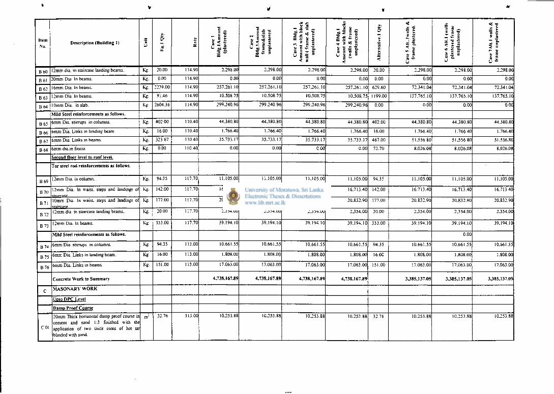
Item No.
Description (Building 1) E 5 ,°f
ce
c
- I i s i s ° | l
£ J = • =
- « ~ i 2 fc
8 2 1 « I 4 =
- ! T ~ cr — _J *e •c .e * t E = ^
is e ~. ^ c *i Q.
< *
- • S i * .£:•= 5 E
MS * S c = 1 R s R c (J c i =
E ~ <
>-. 5 >
c k. <
— c,
R L.
R
— c < C, «• £ a. R If. k. R
Cas
e 6
All.
1 (w
alls
pl
aste
red
fram
e iin
pla
slcr
rd)
=8 -" i ^ i * S
— c
— c
< -
B 6 0 12mm dia. in staircase landing beams.. Kg. 20.00 114.90 22298.00 22298.00 2.298.00 2.298.00 20.00 22298.00 2.298.00 2398.00
B 6 1 20mm Dia. In beams. Kg. 0.00 114.90 0.00 0.00 0.00 0.00 0.00 0.00 0.00 0.00
B 6 : 16mm Dia. In beams. Kg. 2239.00 114.90 2572261.10 2572261.10 257.261.10 2572261.10 629.60 72.341.04 72.341.04 72341.04
B 6 3 12mm Dia. In beams. Kg. 91.46 114.90 10.508.75 10.508.75 10.508.75 10.508.75 1199.00 137.765.10 137.765.10 137.765.10
B 6 4 10mm Dia. in slab. Kg. 2604.36 114.90 299.240.96 2992240.96 299.240.96 2992240.96 0.00 0.00 0.00 0.00
Mild Steel reinforcements as follows.
B 6 5 6mm Dia. stirrups in columns. Kg. 402.00 110.40 44.380.80 44.380.80 44.380.80 44.380.80 402.00 44.380.80 44.380.80 44.380.80
B 6 6 6mm Dia. Links in Landing beam. Kg. 16.00 110.40 1.766.40 1.766.40 1.766.40 1.766.40 16.00 1.766.40 1.766.40 1.766.40
B 6 7 6mm Dia. Links in beams. Kg 323.67 110.40 35.733.17 35.733.17 35.733.17 35.733.17 467.00 51.556.80 51.556.80 51.556.80
B68 6mm dia.in fascia Kg 0.00 110.40 0.00 0.00 0.00 0.00 72.70 8.026.08 8.026.08 8.026.08
Second floor level to roof level.
T o r steel rod reinforcements as follows.
B 6 9 12mm Dia. in column. Kg. 94.35 117.70 11.105.00 11.105.00 11.105.00 11.105.00 94.35 11.105.00 11.105.00 11.105.00
B70 12mm Dia. In waist, steps and landings of Kg. 142.00 117.70 16.713.40 16.713.40 16.713.40 16.713.40 142.00 16.713.40 16.713.40 16.713.40
B 7 1 10mm Dia. In waist, steps and landings of Kg- 177.00 117.70 20.832.90 20.832.90 20.832.90 20.832.90 177.00 20.832.90 20.832.90 20.832.90
B72 12mm dia. in staircase landing beams. Kg. 20.00 117.70 2.354.00 2.354.00 2.354.00 2.354.00 20.00 2.354.00 2.354.00 2354.00
B73 12mm Dia. In beams. Kg. 333.00 117.70 39.194.10 39.194.10 39.194.10 39.194.10 333.00 39.194.10 39.194.10 39.194.10
Mild Steel reinforcements as follows. 0.00
B74 6mm Dia. stirrups in columns. Kg- 94.35 113.00 10.661.55 10.661.55 10.661.55 10.661.55 94.35 10.661.55 10.661.55 10.661.55
B 7 5 6mm Dia. Links in landing beam. Kg 16.00 113.00 1.808.00 1.808.00 1.808.00 1.808.00 16.00 1.808.00 1.808.00 1.808.00
B 7 6 6mm Dia. Links in beams. Kg. 151.00 113.00 17.063.00 17.063.00 17.063.00 17.063.00 151.00 17.063.00 17.063.00 17.063.00
Concrete Work to Summary 4,738,167.89 4,738.167.89 4,738,167.89 4,738,167.89 3385,137.05 3385,137.05 3385,137.05
C MASONARY W O R K
LiDto DPC Level
Damn Proof Course
C 01
20mm Thick horizontal damp proof course in cement and sand 1:3 finished with the application of two thick coats of hot tar blinded with sand.
m" 32.76 313.00 10.253.88 102253.88 10.253.88 10.253.88 32.76 10.253.88 10.253.88 10.253.88

•4
Item No. Description (Building 1) U
nit
Eg-
• Q
ty
Kat
e
Cas
e 1
Bld
g.lA
mou
nt
(pla
ster
ed)
Cas
e 2
Bld
g.lA
mou
nt
fram
e&sl
ab
unpl
aste
red
Cas
e 3
Bld
g.l
Am
ount
wit
h bl
ock
wal
l ( f
ram
e &
sla
b un
plas
tere
d)
Cas
e 4
Bld
g.l
Am
ount
wit
h bl
ocks
(w
alls
St
fram
e un
plas
tere
d)
Alt
erna
tive
.! Q
ty
Cas
e 5
Alt.
. 1 w
alls
St
fra
me
plas
tere
d.
Cas
e 6
Alt
.l (w
alls
pl
aste
red
fram
e un
plas
tere
d)
Cas
e 7A
lt.l
wal
ls &
fr
ame
unpl
aste
red
C02 Random rubble stone work (150 -225mm) in cement and sand 1:5 in wall foundation.
m"' 26.00 3,227.00 83.902.00 83,902.00 83.902.00 83.902.00 26.00 83.902.00 83.902.00 83.902.00
Masonary Work to Summary 94,155.88 94,155.88 94,155.88 94,155.88 94,155.88 94,155.88 94,155.88
D BRICK WORK / CHIP CONCRETE BLOCKWORK Upto first floor Level:
D 0 1 Chip concrete block work in 125mm n r 0.00 366.00 0.00 0.00 96.950.00 96,950.00 350.00 128,100.00 128,100.00 128,100.00
D02 Brick work in cement and sand 1:8 in 225mm walls
m" 350.00 1,018.00 356,300.00 356,300.00 0.00 0.00 0.00 0.00 0.00 0.00
First floor level to second floor level
D03 Chip concrete block work in 125mm m" 0.00 384.00 0.00 0.00 101.850.00 101,850.00 350.00 134,400.00 134.400.00 134,400.00
D04 Brick work in cement and sand 1:8 in 225mm walls
m" 350.00 1,069.00 374,150.00 374,150.00 0.00 0.00 0.00 0.00 0.00 0.00
Second floor to roof level
D 05 Chip concrete block work in 125mm walls
m" 0.00 392.00 0.00 0.00 103,600.00 103,600.00 350.00 137,200.00 137.200.00 137,200.00
D 0 6 Brick work in cement and sand 1:8 in 225mm walls
trf 350.00 1.089.00 381.150.00 381,150.00 0.00 0.00 0.00 0.00 0.00 0.00
Brick work/ Chip concrete block work to Summary 1,111,600.00 1,111,600.00 302,400.00 302,400.00 399,700.00 399,700.00 399,700.00
E STRUCTURAL STEEL WORK
E O ! Steel truss : 18m span No. 7.00 80.000.00 560.000.00 560.000.00 560.000.00 560,000.00 7.00 560.000.00 560,000.00 560.000.00
E 0 2 Supply and tlx 50 x 50 x 6mm angle iron purlin at 750mm c/c .
m 750.00 380.00 285.000.00 285.000.00 285.000.00 285.000.00 750.00 285.000.00 285.000.00 285,000.00
E 0 3
Allow for hiring of mobile crane to hoist and place 11 No. roof trusses. Rate to include for necessary fuel and including crane operator charge.
Item 1.00 250,000.00 250.000.00 250,000.00 250.000.00 250,000.00 1.00 250,000.00 250,000.00 250,000.00
Structural Steel Work to Summary 1,095,000.00 1,095,000.00 1,095,000.00 1,095,000.00 1,095,000.00 1,095,000.00 1,095,000.00
F METAL WORK
Aluminium Doors and Windows.
FOI Aluminium (Non-colour) anodised frame glazed door swing type D l . 1500 x 2850mm hiim
m" 38.52 15.495.00 596.867.40 596.867.40 596.867.40 596.867.40 38.52 596.867.40 596.867.40 596.867.40
1(11

V »
i t em
No. Descript ion (Bu i ld ing 1) E
u
Rat
e
Cas
e 1
B
ldg
.lA
mo
un
t (p
last
ered
)
Cas
e 2
B
ldg
.lA
mo
un
t fr
am
e&
sla
b
un
pla
ster
ed
Ca
se
3
Bld
g.l
Am
ou
nt
wit
h b
lock
w
all
( f
ram
e &
sla
b
un
pla
ster
ed)
Cas
e 4 B
ldg
.l
Am
ou
nt
wit
h b
lock
s (w
alls
& f
ram
e
un
pla
ster
ed)
Alt
ern
ati
ve
.!
Qty
Cas
e 5
Alt
.. 1
wal
ls
& f
ram
e p
last
ered
.
Cas
e 6 A
lt.l
(w
all
s
pla
ster
ed f
ram
e
un
pla
ster
ed)
Cas
e 7
Alt
.l w
alls
&
fra
me
un
pla
ster
ed
F02
Aluminium (non-color) anodized frame glazed door hinged type D2 1050 x 2100mm high
m' 39.69 6.725.00 266.915.25 266.915.25 266.915.25 266.915.25 39.69 266.915.25 266.915.25 266.915.25
F03 Aluminium (Non-color) anodised frame glazed window rype W l . 750 x [950mm hioh
m" 546.93 4.412.00 2.413.055.16 2.413.055.16 2.413.055.16 2.413.055.16 546.93 2.413.055.16 2.413.055.16 2.413.055.16
F04 Fabricate, supply and Fix G.l. rube staircase handrail
rn 70.00 900.00 63.000.00 63.000.00 63.000.00 63.000.00 70.00 63.000.00 63.000.00 63.000.00
M e t a l work to S u m m a r y 3 3 3 9 , 8 3 7 . 8 1 3 3 3 9 , 8 3 7 . 8 1 3 3 3 9 , 8 3 7 . 8 1 3 3 3 9 , 8 3 7 . 8 1 3 3 3 9 , 8 3 7 . 8 1 3 3 3 9 , 8 3 7 . 8 1 3 3 3 9 3 3 7 . 8 1
G C A R P E N T R Y A N D J O I N E R Y
Cei l ing
G01 4.6mmt hick asbestos flat cement sheet ceiling
m" 518.40 1.040.00 539.136.00 539.136.00 539.136.00 539.136.00 518.40 539.136.00 539.136.00 539.136.00
G02 4.6mm. Thick asbestos flat cement sheet ceiling at eaves
m" 316.80 778.00 246.470.40 246.470.40 246.470.40 246.470.40 316.80 246.470.40 246.470.40 246.470.40
Valance and Barse B o a r d 0.00
G03 300 x 25mm thick finished size Ginisapu timber valance board
m 93.60 360.00 33.696.00 33.696.00 33.696.00 33.696.00 93.60 33.696.00 33.696.00 33.696.00
Carpent ry and Joinery w o r k to Stimmarv 8 1 9 3 0 2 . 4 0 8 1 9 3 0 2 . 4 0 8 1 9 3 0 2 . 4 0 8 1 9 3 0 2 . 4 0 8 1 9 3 0 2 . 4 0 8 1 9 3 0 2 . 4 0 8 1 9 3 0 2 . 4 0
H R O O F C O V E R I N G A N D R O O F P L U M B I N G
M a i n Roof
HOI Corrugated asbestos cement sheet roofing m~ 849.12 488.00 414.370.56 414.370.56 414.370.56 414.370.56 849.12 414.370.56 414.370.56 414.370.56
H02 Calicut pattern ridge m 34.80 226.00 7.864.80 7.864.80 7.864.80 7.864.80 34.80 7.864.80 7.864.80 7.864.80
Roof P lumbing 0.00
H03 150 x 100mm Squre PVC eave gutter m 69.60 280.00 19.488.00 19.488.00 19.488.00 19.488.00 69.60 19.488.00 19.488.00 19.488.00
H04 82mm Dia. PVC down pipe m 170.00, 255.00 43.350.00 43.350.00 43.350.00 43.350.00 170.00 43,350.00 43.350.00 43.350.00
Roof Cover ing and Roof P l u m b e r to
S u m m a r y 4 8 5 , 0 7 3 3 6 4 8 5 , 0 7 3 3 6 4 8 5 , 0 7 3 3 6 4 8 5 , 0 7 3 3 6
0.00 4 8 5 . 0 7 3 3 6 4 8 5 , 0 7 3 3 6
J Plastering
JOl Plinth plastering m~ 28.08 187.00 5.250.96 5.250.96 5.250.96 5.250.96 28.08 5.250.96 5.250.96 5.250.96
J02 Plastering external ground floor walls m~ 350.00 173.00 60.550.00 60.550.00 60.550.00 0.00 350.00 60.550.00 60.550.00 0.00
J03 Plastering external First floor walls m" 350.00 182.00 63.700.00 63.700.00 63.700.00 0.00 350.00 63.700.00 63.700.00 0.00
J04 Plastering external second floor walls m" 350.00 190.00 66.500.00 66.500.00 66.500.00 0.00 350.00 66.500.00 66.500.00 0.00
J05 Plastering external columns in ground m" 25.92 173.00 4.484.16 0.00 0.00 0.00 25.92 4.484.16 0.00 0.00
1(15

Item No.
Description (Building 1) c 5 at
re a
e
- I*
c
1 £ •= *^ C 4, » < « « * _ ft «
s £ § as
- ! ^ _ a % I €
w « c
" I s . " < *
s i l l * 1 * 1 a = re c
U | £ =
<
5 4.
re c k.
a.
<
E a. et u S St "7. re
5 1 IT. e (W CC
re u *
— A.
* i s : I t = -g % < - s
* £ a
s s i <3
« * * re — "a. c < = r - ft. «. E re k. u
J06 Plastering external columns in first floor. m" 25.92 182.00 4.717.44 0.00 0.00 0.00 25.92 4.717.44 0.00 0.00
J 07 Plaster external columns in second floor. m" 15.84 190.00 3.009.60 0.00 0.00 0.00 15.84 3.009.60 0.00 0.00
Internal Plastering
J 08 Plastering walls in ground floor. m" 350.00 292.00 1022200.00 102.200.00 102.200.00 0.00 350.00 1022200.00 102.200.00 0.00
J09 Plastering walls in first floor. m' 350.00 307.00 107.450.00 107.450.00 107.450.00 0.00 350.00 107.450.00 107.450.00 0.00
J 10 Plastering walls in second floor. m" 350.00 321.00 112.350.00 112.350.00 112.350.00 0.00 350.00 1 12.350.00 112.350.00 0.00
J 11 Plastering columns in ground floor. m" 103.68 307.00 31.829.76 31.829.76 0.00 0.00 103.68 31.829.76 0.00 0.00 J 12 Plasterinc columns in first floor. m" 103.68 307.00 31.829.76 31.829.76 0.00 0.00 103.68 31.829.76 0.00 0.00
J 13 Plastering columns in second floor. nr 45.36 321.00 14.560.56 14.560.56 0.00 0.00 45.36 14.560.56 0.00 0.00
J 14 Plastering first floor soffii m" 460.00 324.00 149.040.00 0.00 0.00 149.040.00 440.64 142.767.36 142.767.36 142.767.36
J 15 Plastering second floor soffit m" 460.00 348.00 160.080.00 0.00 0.00 160.080.00 440.64 153.342.72 153.342.72 153.342.72
J 16 Plastering first floor beams m2 176.00 324.00 57.024.00 0.00 0.00 0.00 315.30 102.157.20 0.00 0.00 J 17 Plastering second floor beams m2 176.00 348.00 61.248.00 0.00 0.00 0.00 315.30 109.724.40 0.00 0.00 J 18 Plastering roof beams m2 83.00 353.00 29.299.00 0.00 0.00 0.00 83.00 29.299.00 0.00 0.00
Plastering to Summary' 1.065.123 24 596.221.04 518 .000.96 314370 .96 1.145.722.92 814.111.04 301.361.04 K Floor Rendering
KOI 12.5mm thick cement rendering in ground n
m" 518.00 207.00 107.226.00 107226.00 107.226.00 107.226.00 0.00 0.00 0.00 0.00
K02 12.5mm thick cement rendering in first floor.
m" 518.00 217.00 112.406.00 112.406.00 112.406.00 112.406.00 518.00 112.406.00 112.406.00 112.406.00
K03 12.5mm thick cement rendering in second floor.
m" 518.00 228.00 118.104.00 118.104.00 118.104.00 118.104.00 518.00 118.104.00 118.104.00 118.104.00
Floor Rendering to Summary 337.736.00 337.736.00 337.736.00 337.736.00 230310.00 230310 .00 230.510.00 L Painting
L01 Two coats of paint to plinth. m" 28.08 95.00 2.667.60 2.667.60 2.667.60 2.667.60 28.08 2.667.60 2.667.60 2.667.60
L02 One coat of primer and two coats ol weather shield emulsion paint to wall in ground floor.
m" 350.00 196.00 68.600.00 68.600.00 68.600.00 75.460.00 350.00 68.600.00 68.600.00 75.460.00
L03 One coat of primer and rwo coals two coats of weather shield emulsion paint to wall in first floor.
m" 350.00 202.00 70.700.00 70.700.00 70.700.00 77.770.00 350.00 70.700.00 70.700.00 77.770.00
L04 One coat of primer and two coats two coats of weather shield emulsion paint to wall in second floor.
m : 350.00 208.00 72.800.00 72.800.00 72.800.00 80.080.00 350.00 72.800.00 72.800.00 80.080.00
L05 Two coats of Weathershield emulsion paint to isolated columns in ground floor.
m : 25.92 196.00 5.080.32 5.588.35 5.588.35 6.147.19 25.92 5.080.32 5.588.35 5.588.35
L06 Two coals of Weathershield emulsion paint to isolated columns in first floor.
m : 25.92 202.00 5.235.84 5.759.42 5.759.42 6.335.37 25.92 5.235.84 5.759.42 5.759.42
L07 Two coats of Weathershield emulsion paint to isolated columns in second floor.
m : 15.84 208.00 3.294.72 3.624.19 3.624.19 3.986.61 15.84 3.294.72 3.624.19 3.624.19
103

hern No.
Description (Building 1) "c u u:
b es 2
s
- It 8 J |
c £ i " i - t U t i g £
ss "~
c w
i f * f = i n
< *
- £ | -« s i "g e = "Z £ •» * * g cc s cs c (J 1 i =
<
5 b <e e b <
£ "C — b CS «
1 £ «• E g £
- J t X t: < Z £
1 = 5 « 5
<* •= <r. f •5 £ s I
< = r- b b E g ;
L08 One coat of primer and two coats of Emulsion paint approved color to walls in pround floor.
rrf 350.00 168.00 58.800.00 58.800.00 64.680.00 71.148.00 350.00 58.800.00 58.800.00 58.800.00
L 0 9 One coat of primer and two coats of Emulsion paint approved color to walls in first floor.
rrf 350.00 175.00 612250.00 612250.00 67.375.00 67.375.00 350.00 61250.00 61.250.00 61250.00
L 10 One coat of primer and rwo coats of Enamel paint approved color to walls in second floor.
m" 350.00 178.00 62.300.00 62.300.00 68.530.00 68.530.00 350.00 62.300.00 62.300.00 62.300.00
L 11 Two coats of emulsion paint to isolated columns in pround floor.
m" 103.68 168.00 17.418.24 19.160.06 19.160.06 19.160.06 103.68 17.418.24 19.160.06 19.160.06
L 12 Two coats of emulsion paint to isolated columns in first floor.
m" 103.68 175.00 18.144.00 19.958.40 19.958.40 19.958.40 103.68 18.144.00 19.958.40 19.958.40
L 13 Painting first floor slab soffit m" 460.00 168.00 772280.00 85.008.00 85.008.00 77280.00 440.64 74.027.52 74.027.52 74.027.52
L 14 Painting second floor soffit m" 460.00 178.00 81.880.00 90.068.00 90.068.00 81.880.00 440.64 78.433.92 78.433.92 78.433.92
L 15 Painting first floor beams m2 176.00 173.00 30.448.00 33.492.80 33.492.80 33.492.80 315.30 54.546.90 60.001.59 60.001.59 L 16 Painting second floor beams m2 176.00 178.00 31.328.00 34.460.80 34.460.80 34.460.80 315.30 56.123.40 61.735.74 61.735.74 L 17 Paiminp roof beams m2 83.00 183.00 15.189.00 16.707.90 16.707.90 16.707.90 83.00 15.189.00 16.707.90 16.707.90
Ceil ins
L18 Two coats of emulsion paint to asbestos ceiling sheets and two coats of enamel paint to cover fillets and cover mouldings (including eave ceiling).
m" 835.20 180.00 150.336.00 150.336.00 150.336.00 150.336.00 835.20 150.336.00 150.336.00 150.336.00
Valance Board
L 19 Prepare and apply one coat of Primer and rwo coats of gloss enamel paint approve*: color to of valance board.
m" 69.60 167.00 11.623.20 11.62320 11.623.20 11.623.20 69.60 11.623 2 0 11.623.20 11.623.20
Painting to Summary 8442374.92 872.904.73 891,139.73 904.398.93 886.570.66 904.073.90 925J83.90
104

S u m m a r y S h e e t F o r B u i l d i n g 1 A P P E N D I X B 2
rs - 0) o>
rs E _ •c •o 2 ~
Discription
Case
1 B
Idg
.
Am
ou
nt
(pla
stered
)
Case
2 B
Idg
.
fram
e &
sla
l
un
pla
steret
Case
3 B
Idg
ilh
blo
ck
s fr
a
& s
lab
un
pla
slered
Case
4 B
Idg
ilh
blo
ck
s fr
a
& w
all
un
pla
stered
rs o
< -m a £ c -
5 2 ase
6 A
lt.2
bl
Wa
lls
pla
ster
fra
me
un
pla
stered
ase
7 A
lt.2
bl
(Wa
lls&
fra
rr
un
pla
stered
$ 3 o — o E x c a v a t i o n & E a r t h W o r k 236.028.50 236,028.50 236,028.50 236.028.50 236.028.50 236.028.50 236.028.50
C o n c r e t e W o r k 4.832,638.49 4.832.638.49 4.832,638.49 4.832,638.49 4.110,500.45 4,110.500.45 4.110.500.45
M a s o n a r y W o r k
B r i c k w o r k / C h i p c o n c r e t e b l o c k w o r k
94,155.88 94.155.88 94,155.88 94.155.88 94.155.88 94.155.88 94,155.88 M a s o n a r y W o r k
B r i c k w o r k / C h i p c o n c r e t e b l o c k w o r k 1,111,600.00 1.111.600.00 302.400.00 302,400.00 399.700.00 399,700.00 399.700.00
S t r u c t u r a l S tee l W o r k 1.095,000.00 1,095.000.00 1.095,000.00 1.095,000.00 1.095.000.00 1,095,000.00 1.095,000.00
Meta l w o r k 3,339,837.81 3.339.837.81 3,339,837.81 3,339,837.81 3.339.837.81 3.339,837.81 3.339.837.81
C a r p e n t r y a n d J o i n e r y w o r k
R o o f C o v e r i n g a n d R o o f P l u m b e r
819.302.40 819,302.40 819.302.40 r 819.302.40 819,302.40 819.302.40 819,302.40 C a r p e n t r y a n d J o i n e r y w o r k
R o o f C o v e r i n g a n d R o o f P l u m b e r 485,073.36 485.073.36 485,073.36 485,073.36 485.073.36 485.073.36 485,073.36
P l a s t e r i n g
F l o o r R e n d e r i n g
1,065,123.24 596.221.04 518.000.96 314,370.96 1,145,722.92 814,111.04 301.361.04 P l a s t e r i n g
F l o o r R e n d e r i n g 337,736.00 337,736.00 337,736.00 337,736.00 230,510.00 230.510.00 230.510.00
P a i n t i n g 844.374.92 872.904.73 891.139.73 904,398.93 886,570.66 904.073.90 925.283.90 T O T A L A M O U N T O F B . O . Q . 14 .260,870.60 13,820,498.21 1 2 , 9 5 1 , 3 1 3 . 1 3 1 2 , 7 6 0 , 9 4 2 . 3 3 12.842.401.98 1 2 , 5 2 8 . 2 9 3 . 3 4 12,036.753.34
C o s t d i f f e r e n c e 440,372.39 1,309,557.47 1,499,928.27 1,418.468.62 1.732.577.26 2,224,117.26 % V a i a t i o n 3.09 9.18 10.52 9.95 12.15 15.60 % V a i a t i o n
C o n t i n g e n c i e s - 1 0 %
E s c a l a t i o n • 10%
1,426,087.06 1.382,049.82 1,295.131.31 1,276,094.23 1.284.240.20 1.252.829.33 1,203.675.33 C o n t i n g e n c i e s - 1 0 %
E s c a l a t i o n • 10% 1.426.087.06 1,382,049.82 1.295,131.31 1.276.094.23 1.284.240.20 1.252.829.33 1.203,675.33 V A T - 1 5 % 2.139.130.59 2.073.074.73 1,942.696.97 1.914.141.35 1.926.360.30 1.879.244.66 1.805.513.00 T O T A L A M O U N T O F E S T I M A T E 19,252,175.31 1 8 , 6 5 7 , 6 7 2 . 5 9 1 7 , 4 8 4 , 2 7 2 . 7 3 1 7 . 2 2 7 , 2 7 2 . 1 4 17.337,242.67 16.913,196.01 16.249,617.01
C o s t d i f f e r e n c e 594,502.72 1,767,902.58 2,024,903.17 1.914,932.64 2,338,979.30 3,002,556.30 % V a i a t i o n 3.09 9 18 10.52 9.95 12.15 15.60 R a t e p e r S q . M e t e r 12,379.23 1 1 , 9 9 6 . 9 6 1 1 . 2 4 2 . 4 6 11,077221 11,147.92 10.875.25 10 ,448 .57
105

V
Bill of Quantities for Building 2 APPENDIX B3
Iters No.
Description (Building 2) 5-BX
B
~ £ « it «£
r~ i =
<
1 * s K « S
1« 1 N (i R
I I I
= f
5 S t
c c. «• 1 £ " 1
f * f
I s = * I
5 IN
ex
<
*"1 ? ~ Z < <r. 2:
• 4
*• ^ i r ^ S -r t &
< ? i f ^ -
Z 5s fc
< = i
r- « c
A EXCAVATION AND E A R T H WORK
A 0 1 Allow for clearing site Item 50.000.00 1.00 50000 .00 50000 .00 50000 .00 50000 .00 l 50.000 .00 50 .000 .00 50.000.00
A 02 Column pits nr' 272.00 109.00 29648 .00 29648 .00 29648 .00 29648 .00 109 29.64S.00 29 .648 .00 29.648.00
a o ; Wall foundation nr 272.00 19.00 5168 . 00 5168 .00 5168 .00 5168 .00 19 5.16S.O0J 5 .168.00 5. I6S.00
A CM Staircase foundauon nr 272.00 0.90 244.80 244.80 244.80 244.80 0 .9 244.80 244 .80 244.80
Earth Work
(Filling :
A 05 | Approved hard earth filling under floors m' 290.00 551.53 159943.70 159943.70 159943.70 159943.70 551.53 159.943.70 159.943.70 159.943.70
Excavation & Earth Work to Summary 245.004 3 0 245.004 3 0 245.00430 245.00430 245,00430 245.00430 245.00430
B CONCRETE WORK
75mm. Thick lean cement concrete 1:3:6 (40mm) in the following.
B 0 1 Column footings m" 331.00 63.50 21018.50 21018.50 21018.50 21018.50 63.5 21.018 .50 21.018 .50 21.018.50
B 0 2 Staircase foundation m" 331.00 1.15 380.65 380.65 380.65 380.65 1.15 380.65 380.65 380.65
B 0 3 wall foundation m" 331.00 85 .00 28135 . 00 26135 .00 28135 .00 28135 . 00 85 28 .135 .00 2 8 . 1 3 5 . 0 0 28.135.00
Reinforced cement concrete 1:2:4 (20mm) in the following.
0.00
B 0 4 Coiumn footings nr 5.691.00 18.00 102438 .00 102436 .00 102438 .00 102438 .00 18 102.438.00 102.438.00 102.438.00
B 0 5 Staircase footings nr' 5.691.00 0.30 1707.30 1707.30 1707.30 1707.30 0 .3 1.707.30 1.707.30 1.707.30
B 0 6 Staircase wall shaft nr' 5.691.00 1.30 7398.30 7398.30 7398.30 7398.30 1.3 7.398.30 7 .398.30 7.398.30
UDto first floor slab level. Reinforced cement concrete 1:2:4 (20mm; in the following.
B 0 7 Column shaft nr' 5.691.00 12.47 70966.77 70966.77 70966.77 70966.77 12.47 70.966 .77 70 .966 .77 70.966.77
106

Item No.
Description (Building 2) « 5
« I ei Si
11 I 1
w £ <
•"1 — •C V: ~
8 * s * E =• S « H
^ Z 111 = £ J
,K -
% * 1 ~> s Z
£ c — .« x %
5 e ei
<
1 1 2 Z < ~ c -• £; •=
s i t
i l l *ii es «
^ E 3 ^ i ^ w £
11 I** « c > s B*. R
B O ? j Beams nr" 5.691.00 44.27 251940.57 251940 .57 251940.57 251940.57 47.84 272257.44 272257.44 272257.44
B 0 9 Composite slab with precast slab 7 beams 100mm thick floor slab
m" 12253.00 0.00 0.00 0.00 0.00 0.00 518.4 649.55520 649.555 2 0 649.55520
B 10 112.5mm Thick floor slab. rrf 662.00 0.00 0.00 0.00 0.00 0.00 0 0.00 0.00 0.00
B 11 125mm Thick floor slab. rrf 716.00 516.00 370888.00 370888.00 370888.00 370886.00 0 0.00 0.00 0.00
b 12 Waist and steps in staircases. nr 5.691.00 2.60 14796.60 14796.60 14796.60 14796.60 2.6 14.796.60 14.796.60 14.796.60
B 13 150mm. Thick landing slab m staircase. m" 860.00 7220 6192.00 6192.00 6192.00 6192.00 7.2 6.192.00 6.192.00 6.192.00
B 14 Landing beam nr 5.691.00 0.40 2276.40 2276.40 2276.40 2276.40 0,40 2276.40 2276.40 2276.40
b i ; 75mm Thick ceroeni concrete 1: 2 1/2:5 (25mml thick in ground floor slab bedding.
rrf 352.00 518.00 182336.00 182336.00 182336.00 182336.00 0.00 0.00 0.00 0.00
B 16 200mm fascia nr' 5.69 i . 00 0.00 0.00 0.00 0.00 0.00 0.94 5.349.54 5.349.54 5.349.54
Firtst floor level to second floor level. 0.00 0.00
Reinforced Cement Concrete 1:2:4 (20mm) in tbe follfowing.
0.00 0.00
B 17 Composiie slab with precas: slab 7 beams 100mm thick floor slab
rrf 12291.00 0.00 0.00 0.00 0.00 0.00 518.00 668.738.00 668.738.00 668.738.00
B 18 112.5mm Thick floor slab. m" 682.00 0.00 0.00 0.00 0.00 0.00 0.00 0.00 0.00 0.00
B 19 125mm Thick floor slab. nr 738.00 518.00 382284.00 382284.00 382284.00 382284.00 0.00 0.00 0.00 0.00
B20 Column shaft nr" 6.062.00 9.23 55952.26 55952.26 55952.26 55952.26 9.23 55.952.26 55.95226 55.95226
B 21 Beams m' 6.062.00 16.73 101417.26 101417.26 101417.26 101417.26 20.30 123.058.60 123.058.60 123.058.60
B22 Staircase beam nr' 6.062.00 0.40 2424.80 2424.80 2424.80 2424.80 0.40 2.424.80 2.424.80 2.424.80
B23 200mm fascia nr' 6.062.00 0.00 0.00 0.00 0.00 0.00 0.94 5.69828 5.69828 5.69828
Second floor level to roof level
Reinforced Cement Concrete 1:2:4 (20mm) in the follfowirez.
B 24 Column shaft m' 6.367.00 4.78 30434.26 30434.26 30434.26 30434.26 4.78 30.434.26 30.43426 30.434.26
B25 Staircase beam m' 6.367.00 0.40 2546.80 2546.80 2546.80 2546.80 0.40 2.546.80 2.546.80 2.546.80
B26 Roof Beams nr 6.367.00 7 .53 47943.51 47943.51 47943.51 47943.51 7.53 47.943.51 47.943.51 47.943.5!
107

Item No.
Description (Building 2) C
$ ~ E a T
I I
- I <
~- - •= I « 1
i i « f £
t, <« ?
4 = & 5 J< :
6s
1 * ? 4 * s £ c "S .
5 w
<
**i ? S s-< 7. \r. .n «. C « 2 y .=
•e T T
2 l i ^ IT. 5
a »" et
S £ -e 3 « y « 1 5 £
Hi r~ et c
e Form Work 1 I Using ordinary plywood of 15mm thick heading as follows. Unto f irst floor level
B27 Sides of column fooungs nr 245.00 71.00 17395.00 17395.00 17395.00 17395.00 71.00 17.395.00 I7J95.00 17.395.00
B 28 Sides of column shaft nr 693.00 186.00 130284.00 130284.00 130284.00 130284.00 188.00 1302284.00 1302284.00 1302284.00
B29 Sides of staircase foundation. nr 693.00 1.001 693.00 693.00 693.00 693.00 1.00 693.00 693.00 693.00
B30 Sides of staircase shaft. nr 693.00 3.90J 2702.70 2702.70 2702.70 2702.70 3.90 2.702.70 2.702.70 2.702.70
B 3 ! Soffit of siab. nr 594.00 460.00 273240.00 273240.00 273240.00 273240.00 0.00 0.00 0.00 0.00
B 32 jSides and soffit of beams. m' 813.00 161.03 130917.39 130917.39 130917.39 130917.39 172.00 139.836.00 139.836.00 139.836.00
B 33 1 Sides and soffit of tie beams. nr 813.00 184.00 149592.00 149592.00 149592.00 149592.00 184.00 149.592.00 149.592.00 149.592.00
B34 Sides and soffit of staircase with landing. nr 594.00 23.69 14071.86 14071.86 14071.86 14071.86 23.69 14.071.86 14.071.86 14.071.86
j First floor level to second floor level
B35 Soffit of slab. nr 624.00 460.00 287040.00 287040.00 287040.00 287040.00 0.00 0.00 0.00 0.00
B36 Sides of column shaft. nr 727.65 100.00 72765.00 72765.00 72765.00 72765.00 100.00 72.765.00 72.765.00 72.765.00
B37 Sides and soffit of beams. m" 854.00 161.03 137519.62 137519.62 137519.62 137519.62 172.00 146.888.00 146.888.00 146.888.00
B38 Sides and soffit of staircase beam m' 854.00 4.90 4184.60 4184.60 4184.60 4184.60 4.90 4.184.60 4.184.60 4.184.60
B39 200 mm fascia m" 854.00 0.00 0.00 0.00 0.00 0.00 42.12 35.970.48 35.970.48 35.970.48
Second floor to roof level
B40 Sides of coiumn shaft. m" 741.50 100.00 74150.00 74150.00 74150.00 74150.00 100.00 74.150.00 74.150.00 74.150.00
B 4 I Sides and soffit of staircase beam nr 870.00 4.90 4263.00 4263.00 4263.00 4263.00 4.90 42263.00 42263.00 42263.00
B42 Sides and soffit of roof beam nr 870.00 88.02 76577.40 76577.40 76577.40 76577.40 88.02 76.577.40 76.577.40 76.577.40
Reinforements
Upto f irst floor Level
Tor steel rod reinforcements as follows.
B43 10mm dia. In column footings. Kg 112.10 575.00 64457.50 64457.50 64457.50 64457.50 575.00 64.457.50 64.457.50 64.457.50
B44 20mm dia in column shaft Kf- 112.10 1.226.00 137434.60 137434.60 137434.60 137434.60 1.226.00 137.434.60 137.434.60 137.434.60
B45 12mm dia. in column shaft. Kg. 112.10 218.30 24471.43 24471.43 24471.43 24471.43 218.30 24.471.43 24.471.43 24.471.43
B46 10mm dia. Staircase footings Kg. 112.10 14.40 1614.24 1614.24 1614.24 1614.24 14.40 1.614.24 1.614.24 1.614.24
B47 10mm dia. Staircase shaft 112.10 40.00 4484.00 4484.00 4484.00 4484.00 40.00 4.484.00 4.484.00 4.484.00
108

>
Item No.
Description (Building 2) Uni
t
Ral
e 5 U "C
E
2 S
S 1 < C
ase
2 R
ldg.
2 fr
ame
& s
lab
unpl
aste
red
Cas
e 3
Bld
g.2
with
bl
ocks
fra
me
& s
lab
unpl
aste
red)
Cas
e 4
llldg.
2 w
ith
bloc
ks f
ram
e &
w
all u
npla
ster
ed)
& at t: .s
<
b - |_ < <r. 2. b c £ «
.s
Cas
e 6
Alt.
2 bl
dg.
( W
alls
pla
ster
ed
fram
e un
plas
tere
d)
2 £ £ ri *
HI r~ ee c b > s If. ee
B48 20mm dia in beams Kg. 112.10 1.753.00 196511.30 196511.30 196511.30 196511.30 786.65 88.183.47 88.183.47 88.183.47
B 4 9 12mm dia in tie beams Kg. 112.10 1,087.00 121852.70 121852.70 121852.70 121852.70 1,087.00 121.852.70 121.852.70 121.852.70
B50 12mm dia in floor beams Kg. 112.10 14.40 1614.24 1614.24 1614.24 1614.24 460.30 51.599.63 51.599.63 51.599.63
B 5 1 10mm dia. In slab Kg. 112.10 1,467.00 164450.70 164450.70 164450.70 164450.70 0.00 0.00 0.00 0.00
B52 16mm dia in floor beams Kg. 112.10 964.00 108064.40 108064.40 108064.40 108064.40 867.90 97.291.59 97.291.59 97.291.59
Mild steel rod reinforcements as follows.
B53 6mm dia in tie beams Kg. 107.70 652.00 70220.40 70220.40 70220.40 70220.40 820.00 88.314.00 88,314.00 88.314.00
B54 6mm dia. Stirrups in column shaft. Kg 107.70 291.93 31440.86 31440.86 31440.86 31440.86 291.93 31,440.86 31.440.86 31.440.86
B55 6mm dia.in fascia Kg 107.70 0.00 0.00 0.00 0.00 0.00 72.70 7.829.79 7.829.79 7.829.79
Fi rs t floor Level to second floor level. 0.00
Tor steel rod reinforcements as follows. 0.00
B 5 6 20mm Dia. in column. Kg. 114.90 330.00 37917.00 37917.00 37917.00 37917.00 330.00 37.917.00 37.917.00 37.917.00
B57 12mm Dia. in column. Kg 114.90 169.00 19418.10 19418.10 19418.10 19418.10 169.00 19.418.10 19,418.10 19.418.10
B58 12mm Dia. In waist steps and landings of staircase
Kg. 114.90 142.00 16315.80 16315.80 16315.80 16315.80 142.00 16.315.80 16.315.80 16.315.80
B 5 9 I Omm Dia. In waist steps and landings of staircase
Kg 114.90 177.00 20337.30 20337.30 20337.30 20337.30 177.00 20.337.30 20.337.30 20.337.30
B 6 0 12mm dia. in staircase landing beams.. Kg 114.90 20.00 2298.00 2298.00 2298.00 2298.00 20.00 2.298.00 2.298.00 2.298.00
B 6 I 20mm Dia. In beams. Kg. 114.90 1,753.00 201419.70 201419.70 201419.70 201419.70 787.00 90.426.30 90.426.30 90.426.30
B62 16mm Dia. In beams. Kg. 114.90 964.00 110763.60 110763.60 110763.60 110763.60 867.90 99.721.71 99.721.71 99.721.71
B63 12mm Dia. In beams. Kg. 114.90 14.40 1654.56 1654.56 1654.56 1654.56 460.30 52.888.47 52.888.47 52.888.47
B64 10mm Dia. in slab. Kg. 114.90 1.467.00 168558.30 168558.30 168558.30 168558.30 0.00 0.00 0.00 0.00
Mild Steel reinforcements as follows.
B65 6mm Dia. stirrups in columns. Kg. 110.40 402.00 44380.80 44380.80 44380.80 44380.80 402.00 44.380.80 44.380.80 44.380.80
B66 6mm Dia. Links in landing beam. Kg. 110.40 16.00 1766.40 1766.40 1766.40 1766.40 16.00 1.766.40 1.766.40 1.766.40
B67 6mm Dia. Links in beams. Kg- 110.40 529.00 58401.60 58401.60 58401.60 58401.60 820.00 90.528.00 90.528.00 90.528.00
B68 6mm dia.in fascia Kg. 110.40 0.00 0.00 0.00 0.00 0.00 72.70 8.026.08 8.026.08 8.026.08
Second floor level to roof level.
Tor steel rod reinforcements as follows.
B69 12mm Dia. in column. Kg. 117.70 532.00 62616.40 62616.40 62616.40 62616.40 532.00 62.616.40 62.616.40 62.616.40
109

lrem No.
Description (Building 2) = 0. C
5 DC
•B
s
a £
II u i <
ci « "5 S
« i I
^ * ^ £ I £ E = S
* a,
£ f * ^ ~ I £ £ - §• •» = » g =
u *
5
<
— Z < 7. u-. * sy B.
£ "
~ 1 1 5 - =
111 d ^ i
Z E •=
i~ r e
S. < B cs u B70 12mm Dia. In waist, steps and landings of
cra i r ras f Kg- 117.70 142.00 16713.40 16713.40 16713.40 16713.40 142.00 16.713.40 16.713.40 16.713.40
B 7 1 lOmm Dia. In waist, steps and landings of Kg. 117.70 177.00 20832.90 20832.90 20832.90 20832.90 177.00 20.832.90 20.832.90 20.832.90
B72 12mm dia. in staircase landing beams.. Kg. 117.70 20.00 2354.00 2354.00 2354.00 2354.00 20.00 2.354.00 2.354.00 2.354.00
B 7.1 12mm Dia. In beams. Kg. 117.70 14.40 1694.88 1694.88 1694.88 1694.88 14.40 1.694.88 1.694.88 1.694.88
Mild Steel reinforcements as follows.
B74 6mm Dia. stirrups in columns. Kg. 113.00 94.35 10661.55 10661.55 10661.55 10661.55 94.35 10.661.55 10.661.55 10.661.55
B75 6mm Dia. Links in landing beam. Kg. 113.00 16.00 1808.00 1808.00 1808.00 1808.00 16.00 1.808.00 1.808.00 1.808.00
B 76 6mm Dia. Links in beams. Kg. 113.00 154.00 17402.00 17402.00 17402.00 17402.00 154.00 17.402.00 17.402.00 17.402.00
Concrete Work to Summary 4.802,803.21 4.802.803.21 4.802,803.21 4.802,803.21 42325,722.15 4J25.722.15 4J25.722.I5
C MASONARY W O R K
Unto DPC Level
Damp Proof Course
COI 20mm Thick horizontal damp proof course in cement and sand 1:3 finished with the application of two thick coats of hot tai blinded with sand.
m" 313.00 32.76 10253.88 10253.88 10253.88 10253.88 32.76 10253.88 10.253.88 10.253.88
C02 Random rubble stone work (150 - 225mm) in cement and sand 1:5 in wall foundation.
m' 3.227.00 26.00 83902.00 83902.00 83902.00 83902.00 26.00 83.902.00 83.902.00 83.902.00
Masonary Work to Summary 94,155.88 94.155.88 94.155.88 94.155.88 94.155.88 94.155.88 94.155.88
110

Item No.
Description (Building 2) w
Of
re a
5 ei
a
ei H
I f a. c £ e U I <
1 •= •= ox = S
X V. t S a -#S ft, « I i = u i =
Cas
e 3
Bld
g.2
with
bl
ocks
fra
me
& s
lab
unpl
aste
red)
Cas
e 4
Bld
g.2 w
ith
bloc
ks f
ram
e &
w
all
unpl
aste
red)
5 ox
<
— 4 . < ~. IT. «
a, c s 4
EI ~ 4 .
JS a ~. <x g £ = a S ; < V> S * ^ *• S > £ u i
| I ? x « £ t>* £
Hi r - A c a- r> r s u
D B R I C K W O R K / CHIP CONCRETE B L O C K W O R K LiDto first floor Level:
D01 Chip concrete block work in 125mm walls m" 366.00 0.00 0.00 0.00 96.950.00 96.950.00 350.00 128.100.00 128.100.00 128.100.00
D02 Brick work in cement and sand 1:8 in 225mm walls
m" 1.018.00 350.00 356300.00 356300.00 0.00 0.00 0.00 0.00 0.00 0.00
Fi rs t floor level to second floor level 0.00
D03 Chip concrete block work in 125mm walls m" 384.00 0.00 0.00 0.00 101.850.00 101.850.00 350.00 134.400.00 134.400.00 134.400.00
D04 Brick work in cement and sand 1:8 in 225mm walls
m" 1.069.00 350.00 374150.00 374150.00 0.00 0.00 0.00 0.00 0.00 0.00
Second floor to roof level 0.00
D05 Chip concrete block work in 125mm walls m" 392.00 0.00 0.00 0.00 103.600.00 103.600.00 350.00 137.200.00 137.200.00 137.200.00
D06 Brick work in cement and sand 1:8 in 225mm walls
m : 1.089.00 350.00 381150.00 381150.00 0.00 0.00 0.00 0.00 0.00 0.00
Brick work/ Chip concrete block work to Summary
1.111,600.00 1.111,600.00 302 ,400.00 302,400.00 399 ,700.00 399 ,700.00 399,700.00
E S T R U C T U R A L S T E E L W O R K
E 0 1 Steel truss :18m span No. 80.000.00 7.00 560000.00 560000.00 560000.00 560000.00 7 .00 560.000.00 560.000.00 560.000.00
E02 Supply and fix 50 x 50 x 6mm angle iron purlin at 750mm dc .
m 380.00 750.00 285000.00 285000.00 285000.00 285000.00 750.00 285.000.00 285.000.00 285.000.00
E03
Allow for hiring of mobile crane to hoist and place 11 No. roof trusses. Rate to include for necessary fuel and including crane operatot charge.
Item 250.000.00 1.00 250000.00 250000.00 250000.00 250000.00 1.00 250.000.00 250.000.00 250.000.00
Structural Steel Work to Summary 1,095.000.00 1.095,000.00 1,095.000.00 1,095,000.00 1,095.000.00 1,095,000.00 0.00
F M E T A L W O R K 0.00
Aluminium Doors and Windows. 0.00
F 0 1
Aluminium (Non-colour) anodised frame glazed door swing type D l . 1500 x 2850mm high
m" 15.495.00 38.52 596867.40 596867.40 596867.40 596867.40 38.52 596.867.40 596.867.40 596.867.40
111
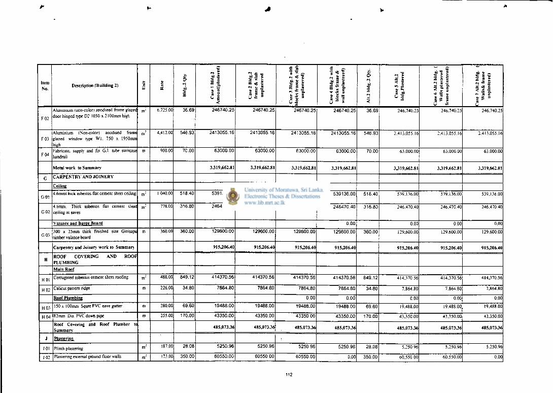
Item No.
Description (Building 2) E ay
a. ex "z E
oi a
| f
« i <
Cas
e 2
Bld
g.2
fram
e &
sla
b un
plas
tere
d * ~ : ST ~ * ? 4 I S e J 5 f , a. "SB 5 1
U -it
in & e.
•ff £ l % 2 I
5 oi 2
»N
<
T5 r4 ft. 2= Cy < o -
. c
^ k By x £ S
_. IK R
ot *; ~ 2 E -o £ es ?. m >S Z
m f- R C ft, 3 R
F02
Aluminium (non-color) anodized frame glazed door hinged type D2 1050 x 2100mm high
m" 6.725.00 36.69 246740.25 246740.25 246740.25 246740.25 36.69 246.740.25 246.740.25 246.740.25
F03 Aluminium fNon-color) anodised frame glazed window type W l . 750 x 1950mm high
m" 4.412.00 546.93 2413055.16 2413055.16 2413055.16 2413055.16 546.93 2.413.055.16 2.413.055.16 2.413.055.16
F04 Fabricate, supply and fix G.I. tube staircase handrail
m 900.00 70.00 63000.00 63000.00 63000.00 63000.00 70.00 63.000.00 63.000.00 63.000.00
Metal work to Summary' 3J19.662.81 3J19.662.81 3J19.662.81 3J19.662.81 3J19.662.81 3J19.662.81 3J19.662.81
G C A R P E N T R Y AND J O I N E R Y
Ceiling
G 01 4.6mmt hick asbestos flat cement sheet ceiling nr 1.040.00 518.40 539136.00 539136.00 539136.00 539136.00 518.40 539.136.00 539.136.00 539.136.00
G02 4.6mm. Thick asbestos flat cement sheet ceiling at eaves
m" 778.00 316.80 246470.40 246470.40 246470.40 246470.40 316.80 246.470.40 246.470.40 246.470.40
Valance and Baree Board 0.00 0.00 0.00 0.00
G03 300 x 25mm thick finished size Ginisapu timber valance board
m 360.00 360.00 129600.00 129600.00 129600.00 129600.00 360.00 129.600.00 129.600.00 129.600.00
Carpentry and Joinery work to Summary 915.206.40 9152206.40 915206.40 915206.40 9152206.40 915206.40 915206.40
H ROOF COVERING AND ROOF PLUMBING Main Roof
HOI Corrugated asbestos cement sheet roofing m' 488.00 849.12 414370.56 414370.56 414370.56 414370.56 849.12 414.370.56 414.370.56 4I4J70.56
H02 Calicut pattern ridge m 226.00 34.80 7864.80 7864.80 7864.80 7864.80 34.80 7.864.80 7.864.80 7.864.80
Roof Plumbirffi 0.00 0.00 0.00 0.00 0.00
H03 150 x 100mm Squre P VC eave gutter m 280.00 69.60 19488.00 19488.00 19488.00 19488.00 69.60 19.488.00 19.488.00 19.488.00
H04 82mm Dia. PVC down pipe m 255.00 170.00 43350.00 43350.00 43350.00 43350.00 170.00 43.350.00 43.350.00 43.350.00
Roof Covering and Roof Plumber to Summary
485.073J6 485.073J6 485.073J6 485.073J6 485.073J6 485.073J6 485.073J6
J Plasteri na
J01 Plinth plastering nr 187.00 28.08 5250.96 5250.96 5250.96 5250.96 28.08 5.250.96 5.250.96 5.250.96
J02 Plastering external ground floor walls nr 173.00 350.00 60550.00 60550.00 60550.00 0.00 350.00 60.550.00 60.550.00 0.00
112

Item No.
Description (Building 2) E 5 BE
£
~ t oi £
i f *- e 5 1 <
Cas
e 2
Bld
g.2
fram
e &
sla
b un
plas
lere
d
Cas
e 3
lllrig
.2 w
ith
bloc
ks f
ram
e &
sla
b un
plas
tere
d)
S w a.
' T = '• s. =
U *
5 oi
Z
<
• k. — ty < ~. V. « * -
«15 1 * 11 H I " * -5 E u £
01 £ — 2 E •= •c a £ M • £ a < = ± r— re c £ S = ee J03 Plastering external first floor walls m" 182.00 350.00 63700.00 63700.00 63700.00 0.00 350.00 63.700.00 63.700.00 0.00
J04 Plastering external second floor walls nr 190.00 350.00 66500.00 66500.00 66500.00 0.00 350.00 66.500.00 66.500.00 0.00
J05 Plastering external columns in ground floor. nf 173.00 25.92 4484.16 0.00 0.00 0.00 25.92 4.484.16 0.00 0.00
J06 Plastering external columns in first floor. m" 182.00 25.92 4717.44 0.00 0.00 0.00 25.92 4.717.44 0.00 0.00
J07 Plaster external columns in second floor. m" 190.00 15.84 3009.60 0.00 0.00 0.00 15.84 3.009.60 0.00 0.00
Internal Plastering
J08 Plastering walls in ground floor. m" 292.00 350.00 102200.00 102200.00 102200.00 0.00 350.00 102.200.00 102.200.00 0.00
J09 Plastering walls in first floor. nr 307.00 350.00 107450.00 107450.00 107450.00 0.00 350.00 107.450.00 107.450.00 0.00
J 10 Plastering walls in second floor. nr 321.00 350.00 112350.00 112350.00 112350.00 0.00 350.00 112.350.00 112.350.00 0.00
J 11 Plastering columns in ground floor. m" 307.00 103.68 31829.76 0.00 0.00 0.00 103.68 31.829.76 0.00 0.00 J 12 Plastering columns in first floor m" 307.00 103.68 31829.76 0.00 0.00 0.00 103.68 31.829.76 0.00 0.00
J 13 Plastering columns in second floor. nr 321.00 45.36 14560.56 0.00 0.00 0.00 45.36 14.560.56 0.00 0.00
J 14 Plastering first floor soffil nr 324.00 456.00 147744.00 0.00 0.00 147.744.00 462.68 149.908.32 149.908.32 149.908.32
J 15 Plastering second floor soffil m" 348.00 456.00 158688.00 0.00 0.00 158.688.00 462.68 161.012.64 161.012.64 161.012.64
J 16 Plastering first floor beams m2 324.00 161.00 52164.00 0.00 0.00 0.00 314.56 101.917.44 0.00 0.00 J 17 Plastering second floor beams m2 348.00 161.00 56028.00 0.00 0.00 0.00 314.56 109.466.88 0.00 0.00 J 18 Plastering roof beams m2 353.00 88.00 31064.00 0.00 0.00 0.00 88.00 31.064.00 0.00 0.00
Plastering to Summary 1.054.120.24 518.000.96 518.000.96 311.682.96 1.161.80132 828.921.92 316.171.92 K Floor Rendering
KOI 12.5mm thick cement rendering in ground f lnnr
m" 207.00 518.00 107226.00 107226.00 107226.00 107226.00 0.00 0.00 0.00 0.00
K 0 2 12.5mm thick cement rendering in first floor. m~ 217.00 518.00 112406.00 112406.00 112406.00 112406.00 518.00 112.406.00 112.406.00 112.406.00
K 0 3 12.5mm thick cement rendering in second floor.
m" 228.00 518.00 118104.00 118104.00 118104.00 118104.00 518.00 118.104.00 118.104.00 118.104.00
Floor Rendering to Summary 337.736.00 337.736.00 337.736.00 337.736.00 230310.00 230310.00 230310.00 L Painting
L 0 1 Two coats of paint to plinth. m" 95.00 28.08 2667.60 2667.60 2667.60 2667.60 28.08 2.667.60 2.667.60 74.906.21
L02 One coat of primer and two coats of weathet shield emulsion paint to wall in ground floor
m" 196.00 350.00 68600.00 68600.00 68600.00 75460.00 350.00 68.600.00 75.460.00 75.460.00
L03 One coal of primer and two coats two coats of weather shield emulsion paint to wall in first floor.
m" 202.00 350.00 70700.00 70700.00 70700.00 77770.00 350.00 70.700.00 70.700.00 77.770.00
L04 One coat of printer and two coats two coats of weather shield emulsion paint to wall in second floor.
nr 208.00 350.00 72800.00 72800.00 72800.00 80080.00 350.00 72.800.00 72.800.00 80.080.00
113

Item No.
Description (Building 2) ee a.
5 f*» ei
E
<N £ 01 £ 2 s - 1 * 1 « i <
"! •= •= M « J
•c ~ -e < ~ » E a s £ 1 y £ =
Cas
e 3
Bld
g.2
with
bl
ocks
fram
e &
sla
b un
plas
tere
d)
Cas
e 4
Bld
g.2
with
bl
ocks
fra
me
&
wal
l unp
last
ered
)
5 oi
<
— £
y 2 .&
2 1 1 * 11 5 7 I
5 £
| 1 r
^ ! 5 1 1 p- ee c c, £ = ee
L 0 5 Two coats of Weathershield emulsion paint to isolated columns in ground floor.
m : 196.00 25.92 5080.32 5588.35 5588.35 6147.19 25.92 5.080.32 5.588.35 5.588.35
L 0 6 Two coats of Weathershield emulsion paint to isolated columns in first floor.
m : 202.00 25.92 5235.84 5759.42 5759.42 6335.37 25.92 5.235.84 5.759.42 5.759.42
L07 Two coats of Weathershield emulsion paint to isolated columns in second floor.
m : 208.00 15.84 3294.72 3624.19 3624.19 3986.61 15.84 3.294.72 3.624.19 3.624.19
LOS One coat of primer and two coats of Emulsion paint approved color to walls in ground floor.
m' 168.00 350.00 58800.00 58800.00 58800.00 64680.00 350.00 58.800.00 58.800.00 64.680.00
L 0 9 One coat of primer and rwo coats of Emulsion paint approved color to walls in first floor.
nf 175.00 350.00 61250.00 61250.00 61250.00 67375.00 350.00 61.250.00 612250.00 67.375.00
L 10 One coat of primer and two coats of Enamel paint approved color to walls in second floor.
nr 178.00 350.00 62300.00 62300.00 62300.00 68530.00 350.00 62.300.00 62.300.00 68.530.00
L 11 Two coats of emulsion paint to isolated columns in ground floor.
m" 168.00 103.68 17418.24 19160.06 19160.06 21076.07 103.68 17.418.24 19.160.06 19.160.06
L 12 Two coats of emulsion paint to isolated columns in first floor.
m" 175.00 103.68 18144.00 19958.40 19958.40 21954.24 103.68 18.144.00 19.958.40 19.958.40
L 13 Painting first floor slab soffit nr 168.00 456.00 76608.00 84268.80 84268.80 76608.00 462.68 77.730.24 77.730.24 77.730.24
L 14 Painting second floor soffit m" 178.00 456.00 81168.00 89284.80 89284.80 81168.00 462.68 82.357.04 82.357.04 82.357.04
L 15 Painting first floor beams m2 173.00 161.00 27853.00 30638.30 30638.30 33702.13 314.56 54.418.88 59.860.77 59.860.77 L 1 6 Painting second floor beams m2 178.00 161.00 28658.00 31523.80 31523.80 34676.18 314.56 55.991.68 61.590.85 61.590.85 L 17 Painting roof beams m2 183.00 88.00 16104.00 17714.40 17714.40 19485.84 88.00 16.104.00 17.714.40 17.714.40
Ceiling
L 18 Two coats of emulsion paint to asbestos ceiling sheets and two coats of enamel paint to cover fillets and cover mouldings (including eave ceiling).
m" 180.00 835.20 150336.00 150336.00 150336.00 150336.00 835.20 150.336.00 150.336.00 150.336.00
Valance Board 0.00
L 19 Prepare and apply one coat of Primer and two coats of gloss enamel paint approved color to of valance board.
m ; 167.00 69.60 11623.20 11623.20 11623.20 11623.20 69.60 11.623.20 11.623.20 11.623.20
Painting to Summary 838.640.92 866-597 J 3 866397233 903.661.43 894.851.76 91928033 1.024,104.14

Summary Sheet For Building 2 APPENDIX B4
Cas
e 1
Bld
g.2
Am
ount
(p
last
ered
)
Cas
e 2
Bld
g.2
fram
e &
sla
b
unpl
aste
red
Cas
e 3
Bld
g.2
with
blo
cks
fram
e &
slab
un
plas
tere
d)
Cas
e 4
Bld
g.2
w
ith b
lock
s fr
ame
&w
all
unpl
aste
red)
Cas
e 5
Alt.
2 b
ldg
.Pla
ster
ed
Cas
e 6
Alt.
2 bl
dg.
(Wal
ls p
last
ered
fr
ame
unpl
aste
red)
Cas
e 7
Alt.
2 b
ldg
. (W
alls
& f
ram
e un
plas
tere
d)
Excavation & Earth Work Concrete Work Masonary Work
Brick work/ Chip concrete block work Structural Steel Work Metal work Carpentry and Joinery work Roof Covering and Roof Plumber Plastering Floor Rendering Painting
245,004.50 245,004.50 245,004.50 245,004.50 245,004.50 245,004.50 245,004.50 Excavation & Earth Work Concrete Work Masonary Work
Brick work/ Chip concrete block work Structural Steel Work Metal work Carpentry and Joinery work Roof Covering and Roof Plumber Plastering Floor Rendering Painting
4,802,803.21 4,802,803.21 4,802,803.21 4,802,803.21 4,325,722.15 4,325,722.15 4,325,722.15
Excavation & Earth Work Concrete Work Masonary Work
Brick work/ Chip concrete block work Structural Steel Work Metal work Carpentry and Joinery work Roof Covering and Roof Plumber Plastering Floor Rendering Painting
94,155.88 94,155.88 94,155.88 94,155.88 94,155.88 94,155.88 94,155.88
Excavation & Earth Work Concrete Work Masonary Work
Brick work/ Chip concrete block work Structural Steel Work Metal work Carpentry and Joinery work Roof Covering and Roof Plumber Plastering Floor Rendering Painting
1,111,600.00 1,111,600.00 302,400.00 302,400.00 399,700.00 399,700.00 399,700.00
Excavation & Earth Work Concrete Work Masonary Work
Brick work/ Chip concrete block work Structural Steel Work Metal work Carpentry and Joinery work Roof Covering and Roof Plumber Plastering Floor Rendering Painting
1,095,000.00 1,095,000.00 1,095,000.00 1,095,000.00 1,095,000.00 1,095,000.00 1,095,000.00
Excavation & Earth Work Concrete Work Masonary Work
Brick work/ Chip concrete block work Structural Steel Work Metal work Carpentry and Joinery work Roof Covering and Roof Plumber Plastering Floor Rendering Painting
3,319,662.81 3,319,662.81 3,319,662.81 3,319,662.81 3,319,662.81 3,319,662.81 3,319,662.81
Excavation & Earth Work Concrete Work Masonary Work
Brick work/ Chip concrete block work Structural Steel Work Metal work Carpentry and Joinery work Roof Covering and Roof Plumber Plastering Floor Rendering Painting
915,206.40 915,206.40 915,206.40 915,206.40 915,206.40 915,206.40 915,206.40
Excavation & Earth Work Concrete Work Masonary Work
Brick work/ Chip concrete block work Structural Steel Work Metal work Carpentry and Joinery work Roof Covering and Roof Plumber Plastering Floor Rendering Painting
485,073.36 485,073.36 485,073.36 485,073.36 485,073.36 485,073.36 485,073.36
Excavation & Earth Work Concrete Work Masonary Work
Brick work/ Chip concrete block work Structural Steel Work Metal work Carpentry and Joinery work Roof Covering and Roof Plumber Plastering Floor Rendering Painting
1,054,120.24 518,000.96 518,000.96 311,682.96 1,161,801.52 828,921.92 316,171.92
Excavation & Earth Work Concrete Work Masonary Work
Brick work/ Chip concrete block work Structural Steel Work Metal work Carpentry and Joinery work Roof Covering and Roof Plumber Plastering Floor Rendering Painting
337,736.00 337,736.00 337,736.00 337,736.00 230,510.00 230,510.00 230,510.00
Excavation & Earth Work Concrete Work Masonary Work
Brick work/ Chip concrete block work Structural Steel Work Metal work Carpentry and Joinery work Roof Covering and Roof Plumber Plastering Floor Rendering Painting 838,640.92 866,597.33 866,597.33 903,661.43 894,851.76 919,280.53 1,024,104.14
TOTAL AMOUNT OF B.O.Q. 14,299,003.32 13,790,840.45 12,981,640.45 12,812,386.55 13,166,688.38 12,858,237.54 12,450,311.15
Cost difference
% Vaiation
Contingencies • 10%
Escalation - 1 0 %
VAT-15%
508,162.87 1,317,362.87 1,486,616.77 1,132,314.95 1,440,765.78 1,848,692.17 Cost difference
% Vaiation
Contingencies • 10%
Escalation - 1 0 %
VAT-15%
3.55 9.21 10.40 7.92 10.08 12.93
Cost difference
% Vaiation
Contingencies • 10%
Escalation - 1 0 %
VAT-15%
1,429,900.33 1,379,084.05 1,298,164.05 1,281,238.65 1,316,668.84 1,285,823.75 1,245,031.12
Cost difference
% Vaiation
Contingencies • 10%
Escalation - 1 0 %
VAT-15%
1,429,900.33 1,379,084.05 1,298,164.05 1,281,238.65 1,316,668.84 1,285,823.75 1,245,031.12
Cost difference
% Vaiation
Contingencies • 10%
Escalation - 1 0 %
VAT-15% 2,144,850.50 2,068,626.07 1,947,246.07 1,921,857.98 1,975,003.26 1,928,735.63 1,867,546.67
TOTAL AMOUNT OF ESTIMATE 19,303,654.48 18,617,634.61 17,525,214.61 17,296,721.84 17,775,029.31 17,358,620.68 16,807,920.06
Cost difference
% Vaiation
Rate per Sq. Meter
686,019.87
3.55
1,778,439.87
9.21
2,006,932.65
10.40
1,528,625.18
7.92
1,945,033.80
10.08
2,495,734.43
12.93
Cost difference
% Vaiation
Rate per Sq. Meter 12,412.33 11,971.22 11,268.79 11,121.86 11,429.42 11,161.66 10,807.56
115