µc/os-ii - korea universityesca.korea.ac.kr/.../an1xxx-rtos/an1013-ucos-ii-microblaze/an-10… ·...
TRANSCRIPT

MicriµmMicriµmMicriµmMicriµm Empowering Embedded Systems
µC/OS-II and the
Xilinx MicroBlaze Processor
Application Note AN-1013
www.Micrium.com

Micriµm µC/µC/µC/µC/OSOSOSOS----IIIIIIII for the Xilinx MicroBlaze
2
Table of Contents 1.00 Introduction 3
1.01 µC/OS-II 3 2.00 The Xilinx MicroBlaze 6 2.01 The MicroBlaze Programmer’s Model 6
3.00 Using the µC/OS-II MicroBlaze Port 9 4.00 Directories and Files 10 4.01 os_cpu.h 10 4.02 os_cpu_c.c 13 4.03 os_cpu_a.s 15
4.03.01 os_cpu_a.s, OSStartHighRdy() 16 4.03.02 os_cpu_a.s, OSCtxSw() 17 4.03.03 Handling Interrupts 22 4.03.04 os_cpu_a.s, OS_CPU_ISR() 24 4.03.05 os_cpu_a.s, OSIntCtxSw() 26 4.03.06 os_cpu_a.s, OS_CPU_SR_Save() 27 4.03.07 os_cpu_a.s, OS_CPU_SR_Restore() 28
4.04 os_dbg.c 28 5.00 An Example Application 29 5.01 bsp.h 29 5.02 bsp.c 29 5.03 helloworld.c 31
6.00 Configuring µC/OS-II 34 7.00 Running the Example Application 36 Licensing 37 Acknowledgements 37 References 37 Contacts 38

Micriµm µC/µC/µC/µC/OSOSOSOS----IIIIIIII for the Xilinx MicroBlaze
3
1.00 Introduction
This application note describes the µC/OS-II port for the Xilinx MicroBlaze soft processor core. A ‘port’ is
the part of the software that adapts µC/OS-II to different processor architectures. The files that comprise
the MicroBlaze port are included with this document, as is an example µC/OS-II-based application. This
application uses a rather generic board support package (which is also included), so it should run on most MicroBlaze systems with little or no modification. In order to run the example application, you will need
µC/OS-II’s processor-independent source code, which is included with this document.
This document assumes that you have µC/OS-II V2.9 or higher.
1.01 µC/OS-II
µC/OS-II is a completely portable, ROMable, scalable, preemptive, real-time, multitasking kernel.
µC/OS-II is written in ANSI C and contains a small portion of assembly language code to adapt it to
different processor architectures. To date, µC/OS-II has been ported to over 45 different processor
architectures.
µC/OS-II Book
The inner workings of µC/OS-II are described in the µC/OS-II book written by author Jean J. Labrosse
(see References at the end of this application note).
Source Code µC/OS-II consists of about 5500 lines of what is probably the cleanest source code in the industry.
Portable Most of µC/OS-II is written in highly portable ANSI C, with target microprocessor-specific code written in
assembly language. Assembly language is kept to a minimum to make µC/OS-II easy to port to other
processors. µC/OS-II can be ported to nearly any microprocessor as long as the microprocessor
provides a stack pointer, and the CPU registers can be pushed onto and popped from the stack. Also, the C compiler should provide either in-line assembly or language extensions that allow you to enable and
disable interrupts from C. µC/OS-II can run on most 8-, 16-, 32-, or even 64-bit microprocessors or
microcontrollers, and DSPs.
ROMable µC/OS-II was designed for embedded applications and thus µC/OS-II can be embedded as part of a
product.
Scalable µC/OS-II was designed so that you can use only the services that you need in your application. This
means that a product with minimal needs can use just a few µC/OS-II services, while another product
can benefit from the full set of features. This allows you to reduce the amount of memory (both RAM and
ROM) needed by µC/OS-II on a per-product basis. Scalability is accomplished with the use of conditional
compilation. Simply specify (through #define constants) which features you need for your application or
product. Everything has been done to reduce both the code and data space required by µC/OS-II.
Micriµm µC/µC/µC/µC/OSOSOSOS----IIIIIIII for the Xilinx MicroBlaze
4
Preemptive µC/OS-II is a fully preemptive real-time kernel. This means that µC/OS-II always runs the highest
priority task that is ready to run. Most commercial kernels are preemptive, and µC/OS-II can offer
comparable or, in many cases, improved performance.
Multitasking µC/OS-II can manage up to 256 tasks. Each task has a unique priority assigned to it, which means that
µC/OS-II does not currently facilitate round-robin scheduling. Thus, there are 256 priority levels.
Deterministic Execution time of all µC/OS-II functions and services is deterministic. This means that you can always
know how much time µC/OS-II will take to execute a function or a service. Except for OSTimeTick()
and some of the event flag services, execution time of µC/OS-II services does not depend on the number
of tasks running in your application.
Task Stacks Each task requires its own stack; however, µC/OS-II allows each task to have a different stack size. This
allows you to reduce the amount of RAM needed in your application. With µC/OS-II’s stack-checking
feature, you can determine exactly how much stack space each task actually requires.
Services µC/OS-II provides a number of system services, such as semaphores, mutual exclusion semaphores,
event flags, message mailboxes, message queues, fixed-sized memory partitions, task management, time management functions, and more.
Interrupt Management Interrupts can suspend the execution of a task. If a high priority task is awakened as a result of the interrupt, then that task will run as soon as the ISR completes.
Robust and Reliable In July of 2000, µC/OS-II was certified in an avionics product by the Federal Aviation Administration
(FAA) for use in commercial aircraft by meeting the demanding requirements of the RTCA DO-178B standard for software used in avionics equipment. In order to meet the requirements of this standard it must be possible to demonstrate through documentation and testing that the software is both robust and safe. This is particularly important for an operating system as it demonstrates that it has the proven
quality to be usable in any application. Every feature, function and line of code of µC/OS-II has been
examined and tested to demonstrate that it is safe and robust enough to be used in Safety Critical Systems where human life is on the line.
MISRA C µC/OS-II is 99% compliant with the Motor Industry Software Reliability Association (MISRA) C Coding
Standards. These standards were created by MISRA to improve the reliability and predictability of C programs in critical automotive systems. Members of the MISRA consortium include Delco Electronics, Ford Motor Company, Jaguar Cars Ltd., Lotus Engineering, Lucas Electronics, Rolls-Royce, Rover Group Ltd., and other firms and universities dedicated to improving safety and reliability in automotive electronics. Full details of this standard can be obtained directly from the MISRA web site, http://www.misra.org.uk. A
detailed µC/OS-II compliance matrix describing all of MISRA's 127 C Coding Rules is available from the
Micriµm web site. This continues the quality focus for µC/OS-II. Customers demand that their RTOS
perform reliably in safety-critical environments.
Used in Hundreds of Products

Micriµm µC/µC/µC/µC/OSOSOSOS----IIIIIIII for the Xilinx MicroBlaze
5
µC/OS-II has been used in hundreds of products from companies all around the world.
Colleges and Universities Many colleges and universities around the world are using µC/OS-II in courses focused on real-time
systems. This ensures that new engineers are trained and ready to use µC/OS-II in products.

Micriµm µC/µC/µC/µC/OSOSOSOS----IIIIIIII for the Xilinx MicroBlaze
6
2.00 The Xilinx MicroBlaze The MicroBlaze is a 32-bit soft processor core. Running at 150 MHz, the MicroBlaze processor delivers 125 D-MIPS for building complex systems for the networking, telecommunication, data communication, embedded, and consumer markets. The MicroBlaze processor features a RISC architecture with Harvard-style separate 32-bit instruction and data busses running at full speed to execute programs and access data from both on-chip and external memory. A standard set of peripherals offers MicroBlaze designers compatibility and reuse. The Embedded Development Kit (EDK), including the MicroBlaze soft processor core and a standard set of peripherals, is available from Xilinx and its distribution partners. The kit features a complete set of GNU-based software tools, including the compiler, assembler, debugger, and linker. Tests of this port were made using version 12.1 of the Xilinx EDK.
2.01 The MicroBlaze Programmer’s Model The visible registers in a MicroBlaze processor are shown in Figure 2-1. The MicroBlaze architecture defines 32 general purpose registers (GPRs). These registers are classified as volatile, non-volatile, and dedicated. The volatile registers are used as temporaries and do not retain values across the function calls. Registers R3 through R12 are volatile, of which R3 and R4 are used for returning values to the caller
function. Registers R5 through R10 are used for passing parameters between sub-routines.
Registers R19 through R31 retain their contents across function calls and are hence termed non-volatile
registers. The callee function is expected to save any non-volatile registers that are being used. These are typically saved to the stack during the prologue and then reloaded during the epilogue. Certain registers are used as dedicated registers and programmers are not expected to use them for any other purpose. Registers R14 through R17, for example, are used for storing the return address from
interrupts, sub-routines, traps, and exceptions, in that order. Sub-routines are called using the branch and link instruction, which saves the current Program Counter (PC) onto register R15. Small data area
pointers are used for accessing certain memory locations with a 16-bit immediate value. The read only (R/O) small data area (SDA) anchor R2 is used to access constants. The other SDA anchor, R13, is
Read/Write (R/W) and is used for accessing the values in the small data read-write section. Register R1 stores the value of the stack pointer and is updated on entry and exit. R1 points to the last
element placed onto the stack. You will notice that the MicroBlaze designers decided to number the bits from left (Bit #0) to right (Bit #31). Also, for this application note, we separated 32-bit numbers with a comma in order to make such numbers more readable (e.g. 0x0000,0010). This is purely a convention.

Micriµm µC/µC/µC/µC/OSOSOSOS----IIIIIIII for the Xilinx MicroBlaze
7
Figure 2-1, MicroBlaze Register Model
MicroBlaze designates certain address locations for handling interrupts and exceptions, as indicated in Table 2-1. Note that the comma separating the hexadecimal number DOES NOT represent a fraction but is used to make the 32-bit number easier to read. This is strictly a convention used in this document.
On MicroBlaze jumps to … Description
Start/Reset 0x0000,0000 Hardware Reset Exception 0x0000,0008 Exception Handler Interrupt 0x0000,0010 Interrupt Handler
Table 2-1, MicroBlaze Interrupt and Exception Handling
R0
R1 (SP)
R2
R3
R4
R5
R6
R7
R8
R9
R10
R11
R12
R13
R14
R15
R16
R17
R18
R19
R20
R21
R22
R23
R24
R25
R26
R27
R28
R29
R30
R31
PC
MSR
0 31
Always contains 0x0000,0000
Stack Pointer
Return address for Interrupts
Return address for Sub-routines
Return address for Trap (Debugger)
Return address for Exceptions
Program Counter
Machine Status Register
Dedicated
Dedicated
Dedicated
Dedicated
Dedicated
Dedicated
Dedicated
Dedicated
Dedicated Reserved for Assembler
Volatile
Volatile
Volatile
Volatile
Volatile
Volatile
Volatile
Volatile
Volatile
Volatile
Return Values
Return Values
Passing Parameters/Temporaries
Passing Parameters/Temporaries
Passing Parameters/Temporaries
Passing Parameters/Temporaries
Passing Parameters/Temporaries
Passing Parameters/Temporaries
Temporaries
Temporaries
R/W, Small Data Area Anchor
R/O, Small Data Area Anchor
Non-Volatile
Non-Volatile
Non-Volatile
Non-Volatile
Non-Volatile
Non-Volatile
Non-Volatile
Non-Volatile
Non-Volatile
Non-Volatile
Non-Volatile
Non-Volatile
Non-Volatile
Special
Special
Micriµm µC/µC/µC/µC/OSOSOSOS----IIIIIIII for the Xilinx MicroBlaze
8
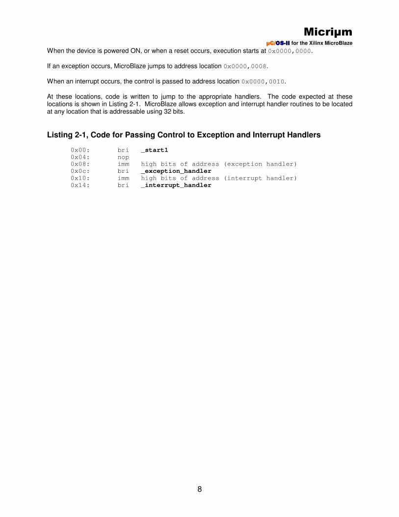
When the device is powered ON, or when a reset occurs, execution starts at 0x0000,0000.
If an exception occurs, MicroBlaze jumps to address location 0x0000,0008.
When an interrupt occurs, the control is passed to address location 0x0000,0010.
At these locations, code is written to jump to the appropriate handlers. The code expected at these locations is shown in Listing 2-1. MicroBlaze allows exception and interrupt handler routines to be located at any location that is addressable using 32 bits.
Listing 2-1, Code for Passing Control to Exception and Interrupt Handlers
0x00: bri _start1 0x04: nop 0x08: imm high bits of address (exception handler)
0x0c: bri _exception_handler 0x10: imm high bits of address (interrupt handler)
0x14: bri _interrupt_handler

Micriµm µC/µC/µC/µC/OSOSOSOS----IIIIIIII for the Xilinx MicroBlaze
9
3.00 Using the µC/µC/µC/µC/OSOSOSOS----IIIIIIII MicroBlaze Port
The µC/OS-II MicroBlaze port is capable of running on most MicroBlaze systems. The port expects an
interrupt controller and a timer/counter peripheral to be present in hardware, but these are essentially the only requirements. If your system includes these two components, you should be able to run the port with little or no modification. At most, you will only need to make slight changes to the BSP files that accompany the port.
The following steps should be taken to use µC/OS-II in your MicroBlaze system:
1. Unzip the “Micrium_SDK.zip” to the location specified by the “Readme.txt” and in section 4.00(pg.
10) 2. Modify the BSP files as described in sections 5.01 and 5.02(pg. 29) 3. Within Xilinx Software Development Kit (SDK), create a new board support package project and
specify µC/OS-II as your board support package; you may then configure µC/OS-II options as
described in section 6.00(pg. 34), Configuring µC/OS-II
After completing the above steps, you will be ready to begin developing µC/OS-II-based applications.
µC/OS-II projects can be built and downloaded using SDK, just like any other software project. You may
want to begin with a simple application to make sure that the port is working properly on your system. One such application is included within the “Micrium_SDK.zip” which will be automatically generated as a project template once the zip file is unzipped. Section 7.00(pg. 36), Running the Example Application, details what must be done to use this application.
Micriµm µC/µC/µC/µC/OSOSOSOS----IIIIIIII for the Xilinx MicroBlaze
10
4.00 Directories and Files The software included in AN-1013.zip, the zip file in which this document is often distributed, is
described below. When you unzip AN-1013.zip, you will find the following directory and files:
Micrium\AppNotes\AN1xxx-RTOS\AN1013-uCOS-II-MicroBlaze ReadMe.txt Micrium_SDK.zip
Micrium\AppNotes\AN1xxx-RTOS\AN1013-uCOS-II-MicroBlaze
This directory contains the documentation for the µC/OS-II MicroBlaze port (i.e. this document). AN-1013.pdf
ReadMe.txt
This file gives instructions as to where the “Micrium_SDK.zip” file should be unzipped. This file must be unzipped in the version number of your Xilinx install path(i.e. Xilinx\12.1) in order for the
µC/OS-II BSP template and the µC/OS-II example application to show up as options in SDK.
Micrium_SDK.zip
This zip file contains the µC/OS-II BSP and example application that will be used by SDK. The
zip file is set up in such a way that when it is unzipped in the correct location, it will automatically place the correct files in their respective locations to allow for the automatic generation of the
BSP and the example application. More specifically, it will place the µC/OS-II bsp where all of the
other bsp templates are located(Xilinx\12.1\SDK\SDK\sw\lib\bsp) and place the example application where all of the other example applications are located(Xilinx\12.1\SDK\SDK\sw\lib\sw_apps).
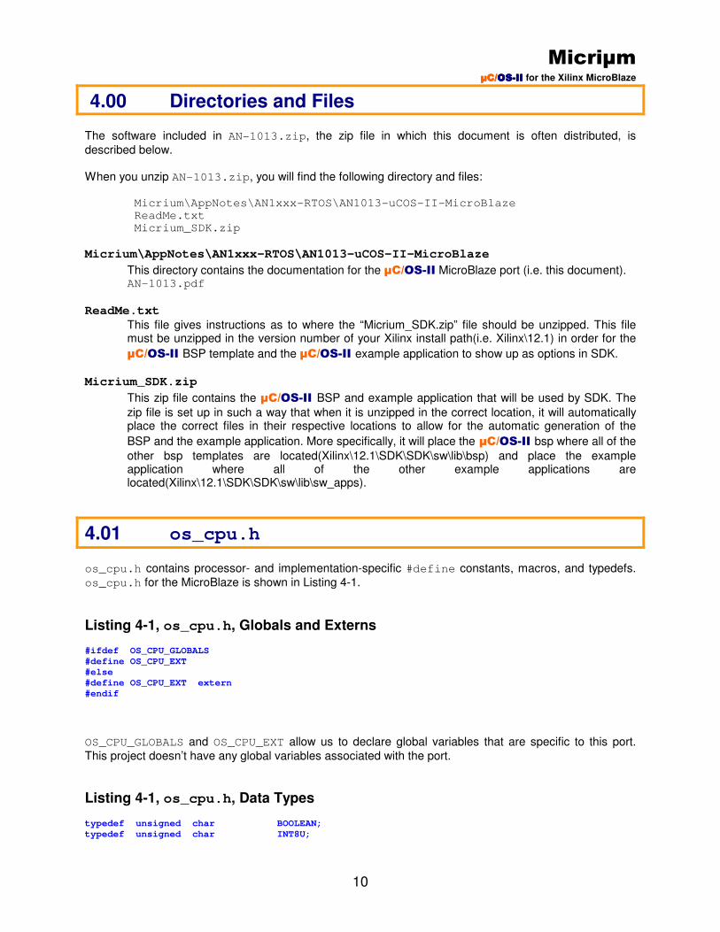
4.01 os_cpu.h
os_cpu.h contains processor- and implementation-specific #define constants, macros, and typedefs.
os_cpu.h for the MicroBlaze is shown in Listing 4-1.
Listing 4-1, os_cpu.h, Globals and Externs #ifdef OS_CPU_GLOBALS
#define OS_CPU_EXT
#else
#define OS_CPU_EXT extern
#endif
OS_CPU_GLOBALS and OS_CPU_EXT allow us to declare global variables that are specific to this port.
This project doesn’t have any global variables associated with the port.
Listing 4-1, os_cpu.h, Data Types typedef unsigned char BOOLEAN;
typedef unsigned char INT8U;

Micriµm µC/µC/µC/µC/OSOSOSOS----IIIIIIII for the Xilinx MicroBlaze
11
typedef signed char INT8S;
typedef unsigned short INT16U; /* (1) */
typedef signed short INT16S;
typedef unsigned int INT32U;
typedef signed int INT32S;
typedef float FP32; /* (2) */
typedef double FP64;
typedef unsigned int OS_STK; /* (3) */
typedef unsigned int volatile OS_CPU_SR; /* (4) */
L4-1(1) If you were to consult the GNU compiler documentation, you would find that a short is
16 bits and an int is 32 bits.
L4-1(2) Floating-point data types are included even though µC/OS-II doesn’t make use of
floating-point numbers. L4-1(3) A stack entry for the MicroBlaze processor is always 32 bits wide, and OS_STK is
declared accordingly. All task stacks must be declared using OS_STK as their data type.
L4-1(4) The status register (the MSR) on the MicroBlaze processor is 32 bits wide. The
OS_CPU_SR data type is used when OS_CRITICAL_METHOD #3 is used (described
below). In fact, this port only supports OS_CRITICAL_METHOD #3 because it’s the
preferred method for µC/OS-II ports.
Listing 4-1, os_cpu.h, OS_ENTER_CRITICAL() and OS_EXIT_CRITICAL() #define OS_CRITICAL_METHOD 3
#define OS_ENTER_CRITICAL() cpu_sr = OS_CPU_SR_Save();
#define OS_EXIT_CRITICAL() OS_CPU_SR_Restore(cpu_sr);
µC/OS-II, as with all real-time kernels, needs to disable interrupts in order to access critical sections of
code and re-enable interrupts when done. µC/OS-II defines two macros to disable and enable interrupts:
OS_ENTER_CRITICAL() and OS_EXIT_CRITICAL(), respectively. µC/OS-II defines three ways to
implement these macros, but a µC/OS-II port only needs to use one of the three methods. MicroC/OS-II,
The Real-Time Kernel, 2nd
Edition (see References, at the end of this document) describes the three different methods. The appropriate method for a given project depends on the processor and compiler. The preferred method is OS_CRITICAL_METHOD #3, which is used for the MicroBlaze port
OS_CRITICAL_METHOD #3 implements OS_ENTER_CRITICAL() by calling a function that will save the
status register of the CPU in a variable. OS_EXIT_CRITICAL() invokes another function to restore the
status register from the variable. The code for these two functions is declared in os_cpu_a.s, which is
described in subsequent sections of this document.
Listing 4-1, os_cpu.h, Stack Growth
#define OS_STK_GROWTH 1
The stacks on the MicroBlaze grow from high memory to low memory. This convention is indicated to
µC/OS-II by setting OS_STK_GROWTH to 1.
Micriµm µC/µC/µC/µC/OSOSOSOS----IIIIIIII for the Xilinx MicroBlaze
12
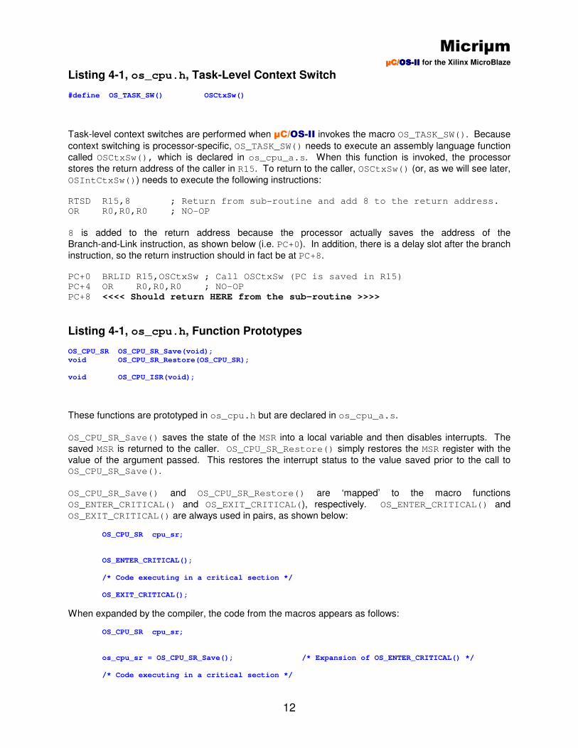
Listing 4-1, os_cpu.h, Task-Level Context Switch #define OS_TASK_SW() OSCtxSw()
Task-level context switches are performed when µC/OS-II invokes the macro OS_TASK_SW(). Because
context switching is processor-specific, OS_TASK_SW() needs to execute an assembly language function
called OSCtxSw(), which is declared in os_cpu_a.s. When this function is invoked, the processor
stores the return address of the caller in R15. To return to the caller, OSCtxSw() (or, as we will see later,
OSIntCtxSw()) needs to execute the following instructions:
RTSD R15,8 ; Return from sub-routine and add 8 to the return address. OR R0,R0,R0 ; NO-OP
8 is added to the return address because the processor actually saves the address of the
Branch-and-Link instruction, as shown below (i.e. PC+0). In addition, there is a delay slot after the branch
instruction, so the return instruction should in fact be at PC+8.
PC+0 BRLID R15,OSCtxSw ; Call OSCtxSw (PC is saved in R15) PC+4 OR R0,R0,R0 ; NO-OP
PC+8 <<<< Should return HERE from the sub-routine >>>>
Listing 4-1, os_cpu.h, Function Prototypes OS_CPU_SR OS_CPU_SR_Save(void);
void OS_CPU_SR_Restore(OS_CPU_SR);
void OS_CPU_ISR(void);
These functions are prototyped in os_cpu.h but are declared in os_cpu_a.s.
OS_CPU_SR_Save() saves the state of the MSR into a local variable and then disables interrupts. The
saved MSR is returned to the caller. OS_CPU_SR_Restore() simply restores the MSR register with the
value of the argument passed. This restores the interrupt status to the value saved prior to the call to OS_CPU_SR_Save().
OS_CPU_SR_Save() and OS_CPU_SR_Restore() are ‘mapped’ to the macro functions
OS_ENTER_CRITICAL() and OS_EXIT_CRITICAL(), respectively. OS_ENTER_CRITICAL() and
OS_EXIT_CRITICAL() are always used in pairs, as shown below:
OS_CPU_SR cpu_sr;
OS_ENTER_CRITICAL();
/* Code executing in a critical section */
OS_EXIT_CRITICAL();
When expanded by the compiler, the code from the macros appears as follows:
OS_CPU_SR cpu_sr;
os_cpu_sr = OS_CPU_SR_Save(); /* Expansion of OS_ENTER_CRITICAL() */
/* Code executing in a critical section */

Micriµm µC/µC/µC/µC/OSOSOSOS----IIIIIIII for the Xilinx MicroBlaze
13
OS_CPU_SR_Restore(cpu_sr); /* Expansion of OS_EXIT_CRITICAL() */
OS_CPU_ISR(), which is described in a later section of this document, is the entry point for all CPU
interrupts.
4.02 os_cpu_c.c
A µC/OS-II port requires that you write ten fairly simple C functions:
OSInitHookBegin() OSInitHookEnd() OSTaskCreateHook() OSTaskDelHook() OSTaskIdleHook() OSTaskStatHook()
OSTaskStkInit() Described in this section. OSTaskSwHook() OSTCBInitHook() OSTimeTickHook()
µC/OS-II really only requires OSTaskStkInit(). The other functions MUST be declared but can be
empty.
OSTaskIdleHook() is called when µC/OS-II has no other task to run. As described in MicroC/OS-II,
The Real-Time Kernel, 2nd
Edition (see References, at the end of this document), OSTaskIdleHook()
can be used to place the CPU in a low power mode.
To use the µC/OS-II required functions declared in this file, the MISCELLANEOUS parameter
OS_CPU_HOOKS_EN should be set to 1 using your project’s Board Support Package Settings. If
OS_CPU_HOOKS_EN is set to 0, then you must declare the functions listed above in another file. You
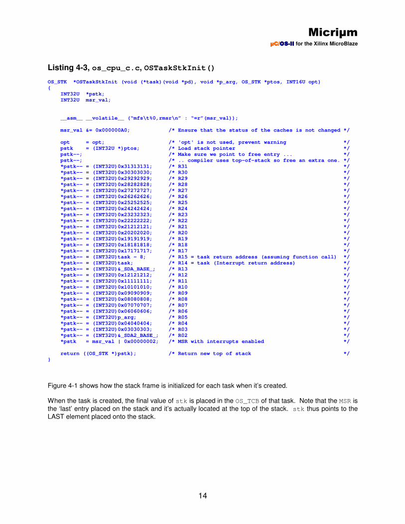
should thus note that these functions MUST always be declared even though they might not contain any code. Listing 4-3 shows the code for OSTaskStkInit(). You should note that we initialized the CPU registers
to values corresponding to their register number. This makes it convenient to find the registers on the stack when you use a debugger. Also, R16 is not saved onto the stack since it’s used by the debugger
and we don’t want to interfere with the debugger during context switching. The GNU compiler also uses two data ‘anchors’: _SDA_BASE_ occupies R13 and _SDA2_BASE_ is in R2.
As per the MicroBlaze register usage convention, the first argument of a function is passed in R5. Recall
that a task is declared as shown in Listing 4-2. The task receives an optional argument, p_arg. That’s
why p_arg is passed in R5 when the task’s stack is created by OSTaskStkInit() (see Listing 4-3).
Listing 4-2, µC/µC/µC/µC/OSOSOSOS----IIIIIIII Task void MyTask (void *p_arg)
{
/* Do something with ‘p_arg’, optional */
while (1) {
/* Task body */
}
}
Micriµm µC/µC/µC/µC/OSOSOSOS----IIIIIIII for the Xilinx MicroBlaze
14
Listing 4-3, os_cpu_c.c, OSTaskStkInit() OS_STK *OSTaskStkInit (void (*task)(void *pd), void *p_arg, OS_STK *ptos, INT16U opt)
{
INT32U *pstk;
INT32U msr_val;
__asm__ __volatile__ (“mfs\t%0,rmsr\n” : “=r”(msr_val));
msr_val &= 0x000000A0; /* Ensure that the status of the caches is not changed */
opt = opt; /* 'opt' is not used, prevent warning */
pstk = (INT32U *)ptos; /* Load stack pointer */
pstk--; /* Make sure we point to free entry ... */
pstk--; /* .. compiler uses top-of-stack so free an extra one. */
*pstk-- = (INT32U)0x31313131; /* R31 */
*pstk-- = (INT32U)0x30303030; /* R30 */
*pstk-- = (INT32U)0x29292929; /* R29 */
*pstk-- = (INT32U)0x28282828; /* R28 */
*pstk-- = (INT32U)0x27272727; /* R27 */
*pstk-- = (INT32U)0x26262626; /* R26 */
*pstk-- = (INT32U)0x25252525; /* R25 */
*pstk-- = (INT32U)0x24242424; /* R24 */
*pstk-- = (INT32U)0x23232323; /* R23 */
*pstk-- = (INT32U)0x22222222; /* R22 */
*pstk-- = (INT32U)0x21212121; /* R21 */
*pstk-- = (INT32U)0x20202020; /* R20 */
*pstk-- = (INT32U)0x19191919; /* R19 */
*pstk-- = (INT32U)0x18181818; /* R18 */
*pstk-- = (INT32U)0x17171717; /* R17 */
*pstk-- = (INT32U)task - 8; /* R15 = task return address (assuming function call) */
*pstk-- = (INT32U)task; /* R14 = task (Interrupt return address) */
*pstk-- = (INT32U)&_SDA_BASE_; /* R13 */
*pstk-- = (INT32U)0x12121212; /* R12 */
*pstk-- = (INT32U)0x11111111; /* R11 */
*pstk-- = (INT32U)0x10101010; /* R10 */
*pstk-- = (INT32U)0x09090909; /* R09 */
*pstk-- = (INT32U)0x08080808; /* R08 */
*pstk-- = (INT32U)0x07070707; /* R07 */
*pstk-- = (INT32U)0x06060606; /* R06 */
*pstk-- = (INT32U)p_arg; /* R05 */
*pstk-- = (INT32U)0x04040404; /* R04 */
*pstk-- = (INT32U)0x03030303; /* R03 */
*pstk-- = (INT32U)&_SDA2_BASE_; /* R02 */
*pstk = msr_val | 0x00000002; /* MSR with interrupts enabled */
return ((OS_STK *)pstk); /* Return new top of stack */
}
Figure 4-1 shows how the stack frame is initialized for each task when it’s created. When the task is created, the final value of stk is placed in the OS_TCB of that task. Note that the MSR is
the ‘last’ entry placed on the stack and it’s actually located at the top of the stack. stk thus points to the
LAST element placed onto the stack.

Micriµm µC/µC/µC/µC/OSOSOSOS----IIIIIIII for the Xilinx MicroBlaze
15
Figure 4-1, The Stack Frame for Each Task
4.03 os_cpu_a.s
A µC/OS-II port requires that you write four fairly simple assembly language functions. These functions
are needed because you normally cannot save/restore registers from C functions. The four functions are:
OSStartHighRdy() OSCtxSw() OSIntCtxSw() OS_CPU_ISR()
4.03.01 os_cpu_a.s, OSStartHighRdy()
OSTCBStkPtr
R2 (_SDA2_BASE)
R3
R4
R5 (p_arg)
R6
R7
R8
R9
R10
R11
R12
R13 (_SDA_BASE_)
R14 (task)
R15 (task – 8)
R17
R18
R20
R21
R22
R23
R24
R25
R26
R27
R28
R29
R30
R31
MSR
OS_TCB
Low Memory
High Memory
stk
ptos
R19
Micriµm µC/µC/µC/µC/OSOSOSOS----IIIIIIII for the Xilinx MicroBlaze
16
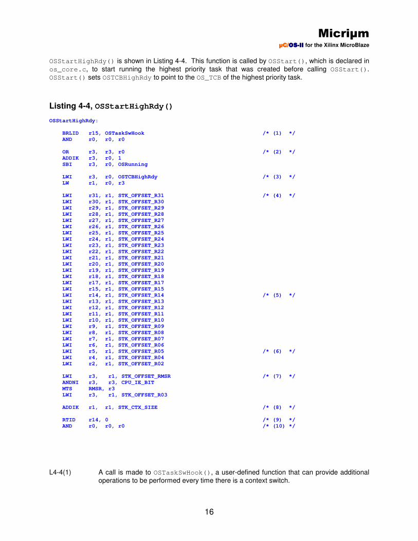
OSStartHighRdy() is shown in Listing 4-4. This function is called by OSStart(), which is declared in
os_core.c, to start running the highest priority task that was created before calling OSStart().
OSStart() sets OSTCBHighRdy to point to the OS_TCB of the highest priority task.
Listing 4-4, OSStartHighRdy() OSStartHighRdy:
BRLID r15, OSTaskSwHook /* (1) */
AND r0, r0, r0
OR r3, r3, r0 /* (2) */
ADDIK r3, r0, 1
SBI r3, r0, OSRunning
LWI r3, r0, OSTCBHighRdy /* (3) */
LW r1, r0, r3
LWI r31, r1, STK_OFFSET_R31 /* (4) */
LWI r30, r1, STK_OFFSET_R30
LWI r29, r1, STK_OFFSET_R29
LWI r28, r1, STK_OFFSET_R28
LWI r27, r1, STK_OFFSET_R27
LWI r26, r1, STK_OFFSET_R26
LWI r25, r1, STK_OFFSET_R25
LWI r24, r1, STK_OFFSET_R24
LWI r23, r1, STK_OFFSET_R23
LWI r22, r1, STK_OFFSET_R22
LWI r21, r1, STK_OFFSET_R21
LWI r20, r1, STK_OFFSET_R20
LWI r19, r1, STK_OFFSET_R19
LWI r18, r1, STK_OFFSET_R18
LWI r17, r1, STK_OFFSET_R17
LWI r15, r1, STK_OFFSET_R15
LWI r14, r1, STK_OFFSET_R14 /* (5) */
LWI r13, r1, STK_OFFSET_R13
LWI r12, r1, STK_OFFSET_R12
LWI r11, r1, STK_OFFSET_R11
LWI r10, r1, STK_OFFSET_R10
LWI r9, r1, STK_OFFSET_R09
LWI r8, r1, STK_OFFSET_R08
LWI r7, r1, STK_OFFSET_R07
LWI r6, r1, STK_OFFSET_R06
LWI r5, r1, STK_OFFSET_R05 /* (6) */
LWI r4, r1, STK_OFFSET_R04
LWI r2, r1, STK_OFFSET_R02
LWI r3, r1, STK_OFFSET_RMSR /* (7) */
ANDNI r3, r3, CPU_IE_BIT
MTS RMSR, r3
LWI r3, r1, STK_OFFSET_R03
ADDIK r1, r1, STK_CTX_SIZE /* (8) */
RTID r14, 0 /* (9) */
AND r0, r0, r0 /* (10) */
L4-4(1) A call is made to OSTaskSwHook(), a user-defined function that can provide additional
operations to be performed every time there is a context switch.
Micriµm µC/µC/µC/µC/OSOSOSOS----IIIIIIII for the Xilinx MicroBlaze
17
L4-4(2) The µC/OS-II flag OSRunning is set to TRUE, indicating that µC/OS-II will be running
once the first task is started. L4-4(3) We then get the pointer to the task’s top-of-stack (was stored by OSTaskCreate() or
OSTaskCreateExt()). See Figure 4-1 (stk is stored in the OS_TCB of the created
task). L4-4(4) We then load all the registers from the task’s stack (except R0 and R1). R0 is never
stored because it always contains 0x0000,0000. R1 is actually the Stack Pointer (SP),
which was stored in the OS_TCB of the task. Note that we used STK_OFFSET_??? labels
instead of hard-coding numbers for stack offsets. This allows us to easily change where registers are placed on the stack frame. STK_OFFSET_??? labels are declared at the
beginning of os_cpu_a.s.
L4-4(5) When the task is created, OSTaskCreate() or OSTaskCreateExt() places the
starting address of the task in R14.
L4-4(6) When the task is created, OSTaskCreate() or OSTaskCreateExt() places the
argument to pass to the task in R5.
L4-4(7) The last value that was added to the stack by OSTaskStkInit() is placed in the MSR.
Subsequently, R3, which was used as a temporary location for this stack entry, is loaded
with the appropriate data. L4-4(8) The stack frame is then cleaned up by moving the stack pointer up by the number of
bytes used to store all the registers. We add this number to the stack pointer since those registers are now in the CPU.
L4-4(9) We finally perform a return from interrupt, which will cause the MicroBlaze to start
executing the task’s code. This instruction ALSO sets the IE bit in the MSR register to 1,
enabling interrupts for the task. L4-4(10) A NO-OP instruction is inserted to fill the delay slot.
4.03.02 os_cpu_a.s, OSCtxSw() A task-level context switch occurs when a task is no longer able to run. For example, if your code calls OSTimeDly(10), then the current task needs to be suspended until 10 clock ticks expire. Since the task
can no longer run, µC/OS-II needs to find the next most important task that is ready to run and resume
execution of that task. The flow of code is as follows: Your task calls OSTimeDly(10);
OSTimeDly() calls OS_Sched();
OS_Sched() disables Interrupts;
OS_Sched() finds the highest priority task that’s ready to run;
OS_Sched() calls OSCtxSw();
OSCtxSw() performs the context switch;
Execution resumes in the new task;
Micriµm µC/µC/µC/µC/OSOSOSOS----IIIIIIII for the Xilinx MicroBlaze
18
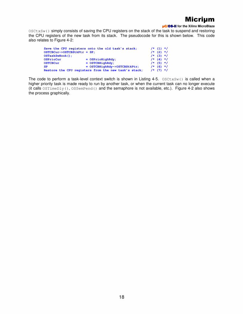
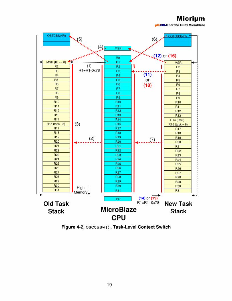
OSCtxSw() simply consists of saving the CPU registers on the stack of the task to suspend and restoring
the CPU registers of the new task from its stack. The pseudocode for this is shown below. This code also relates to Figure 4-2: Save the CPU registers onto the old task’s stack; /* (1) */
OSTCBCur->OSTCBStkPtr = SP; /* (2) */
OSTaskSwHook(); /* (3) */
OSPrioCur = OSPrioHighRdy; /* (4) */
OSTCBCur = OSTCBHighRdy; /* (5) */
SP = OSTCBHighRdy->OSTCBStkPtr; /* (6) */
Restore the CPU registers from the new task’s stack; /* (7) */
The code to perform a task-level context switch is shown in Listing 4-5. OSCtxSw() is called when a
higher priority task is made ready to run by another task, or when the current task can no longer execute (it calls OSTimeDly(), OSSemPend() and the semaphore is not available, etc.). Figure 4-2 also shows
the process graphically.
Micriµm µC/µC/µC/µC/OSOSOSOS----IIIIIIII for the Xilinx MicroBlaze
19
Figure 4-2, OSCtxSw(), Task-Level Context Switch
R2
R3
R4
R5
R6
R7
R8
R9
R10
R11
R12
R13
R14
R15 (task - 8)
R17
R18
R19
R20
R21
R22
R23
R24
R25
R26
R27
R28
R29
R30
R31
MSR (IE == 0)
OSTCBStkPtr
R2
R3
R4
R5
R6
R7
R8
R9
R10
R11
R12
R13
R14 (task)
R15 (task – 8)
R17
R18
R19
R20
R21
R22
R23
R24
R25
R26
R27
R28
R29
R30
R31
MSR
OSTCBStkPtr
MSR
R2
R3
R4
R5
R6
R7
R8
R9
R10
R11
R12
R13
R14
R15
R17
R18
R19
R20
R21
R22
R23
R24
R25
R26
R27
R28
R29
R30
R31
R0
R1
PC
(1)
R1=R1-0x78
(4)
(5) (6)
(7) (2)
(12) or (16)
(11) or
(18)
MicroBlaze
CPU
New Task
Stack
Old Task
Stack
(14) or (19)
R1=R1+0x78
High
Memory
(3)

Micriµm µC/µC/µC/µC/OSOSOSOS----IIIIIIII for the Xilinx MicroBlaze
20
Listing 4-5, OSCtxSw() OSCtxSw:
ADDIK r1, r1, -STK_CTX_SIZE /* (1) */
SWI r2, r1, STK_OFFSET_R02 /* (2) */
SWI r3, r1, STK_OFFSET_R03
SWI r4, r1, STK_OFFSET_R04
SWI r5, r1, STK_OFFSET_R05
SWI r6, r1, STK_OFFSET_R06
SWI r7, r1, STK_OFFSET_R07
SWI r8, r1, STK_OFFSET_R08
SWI r9, r1, STK_OFFSET_R09
SWI r10, r1, STK_OFFSET_R10
SWI r11, r1, STK_OFFSET_R11
SWI r12, r1, STK_OFFSET_R12
SWI r13, r1, STK_OFFSET_R13
SWI r14, r1, STK_OFFSET_R14
SWI r15, r1, STK_OFFSET_R15 /* (3) */
SWI r17, r1, STK_OFFSET_R17
SWI r18, r1, STK_OFFSET_R18
SWI r19, r1, STK_OFFSET_R19
SWI r20, r1, STK_OFFSET_R20
SWI r21, r1, STK_OFFSET_R21
SWI r22, r1, STK_OFFSET_R22
SWI r23, r1, STK_OFFSET_R23
SWI r24, r1, STK_OFFSET_R24
SWI r25, r1, STK_OFFSET_R25
SWI r26, r1, STK_OFFSET_R26
SWI r27, r1, STK_OFFSET_R27
SWI r28, r1, STK_OFFSET_R28
SWI r29, r1, STK_OFFSET_R29
SWI r30, r1, STK_OFFSET_R30
SWI r31, r1, STK_OFFSET_R31
MFS r3, RMSR /* (4) */
SWI r3, r1, STK_OFFSET_RMSR
LWI r3, r0, OSTCBCur /* (5) */
SW r1, r0, r3
BRLID r15, OSTaskSwHook
AND r0, r0, r0
LBUI r3, r0, OSPrioHighRdy
SBI r3, r0, OSPrioCur
LWI r3, r0, OSTCBHighRdy
SWI r3, r0, OSTCBCur
LW r1, r0, r3 /* (6) */
LWI r31, r1, STK_OFFSET_R31 /* (7) */
LWI r30, r1, STK_OFFSET_R30
LWI r29, r1, STK_OFFSET_R29
LWI r28, r1, STK_OFFSET_R28
LWI r27, r1, STK_OFFSET_R27
LWI r26, r1, STK_OFFSET_R26
LWI r25, r1, STK_OFFSET_R25
LWI r24, r1, STK_OFFSET_R24
LWI r23, r1, STK_OFFSET_R23
LWI r22, r1, STK_OFFSET_R22
LWI r21, r1, STK_OFFSET_R21
LWI r20, r1, STK_OFFSET_R20
LWI r19, r1, STK_OFFSET_R19
LWI r18, r1, STK_OFFSET_R18
LWI r17, r1, STK_OFFSET_R17
LWI r15, r1, STK_OFFSET_R15
LWI r14, r1, STK_OFFSET_R14
Micriµm µC/µC/µC/µC/OSOSOSOS----IIIIIIII for the Xilinx MicroBlaze
21
LWI r13, r1, STK_OFFSET_R13
LWI r12, r1, STK_OFFSET_R12
LWI r11, r1, STK_OFFSET_R11
LWI r10, r1, STK_OFFSET_R10
LWI r9, r1, STK_OFFSET_R09
LWI r8, r1, STK_OFFSET_R08
LWI r7, r1, STK_OFFSET_R07
LWI r6, r1, STK_OFFSET_R06
LWI r5, r1, STK_OFFSET_R05
LWI r4, r1, STK_OFFSET_R04
LWI r2, r1, STK_OFFSET_R02
LWI r3, r1, STK_OFFSET_RMSR /* (8) */
ANDI r3, r3, CPU_IE_BIT /* (9) */
BNEI r3, OSCtxSw_SavedByISR /* (10) */
LWI r3, r1, STK_OFFSET_RMSR /* (11) */
MTS RMSR,r3 /* (12) */
LWI r3, r1, STK_OFFSET_R03 /* (13) */
ADDIK r1, r1, STK_CTX_SIZE /* (14) */
RTSD r15, 8 /* (15) */
AND r0, r0, r0
OSCtxSw_SavedByISR:
LWI r3, r1, STK_OFFSET_RMSR /* (16) */
ANDNI r3, r3, CPU_IE_BIT /* (17) */
MTS RMSR,r3
LWI r3, r1, STK_OFFSET_R03 /* (18) */
ADDIK r1, r1, STK_CTX_SIZE /* (19) */
RTID r14, 0 /* (20) */
AND r0, r0, r0
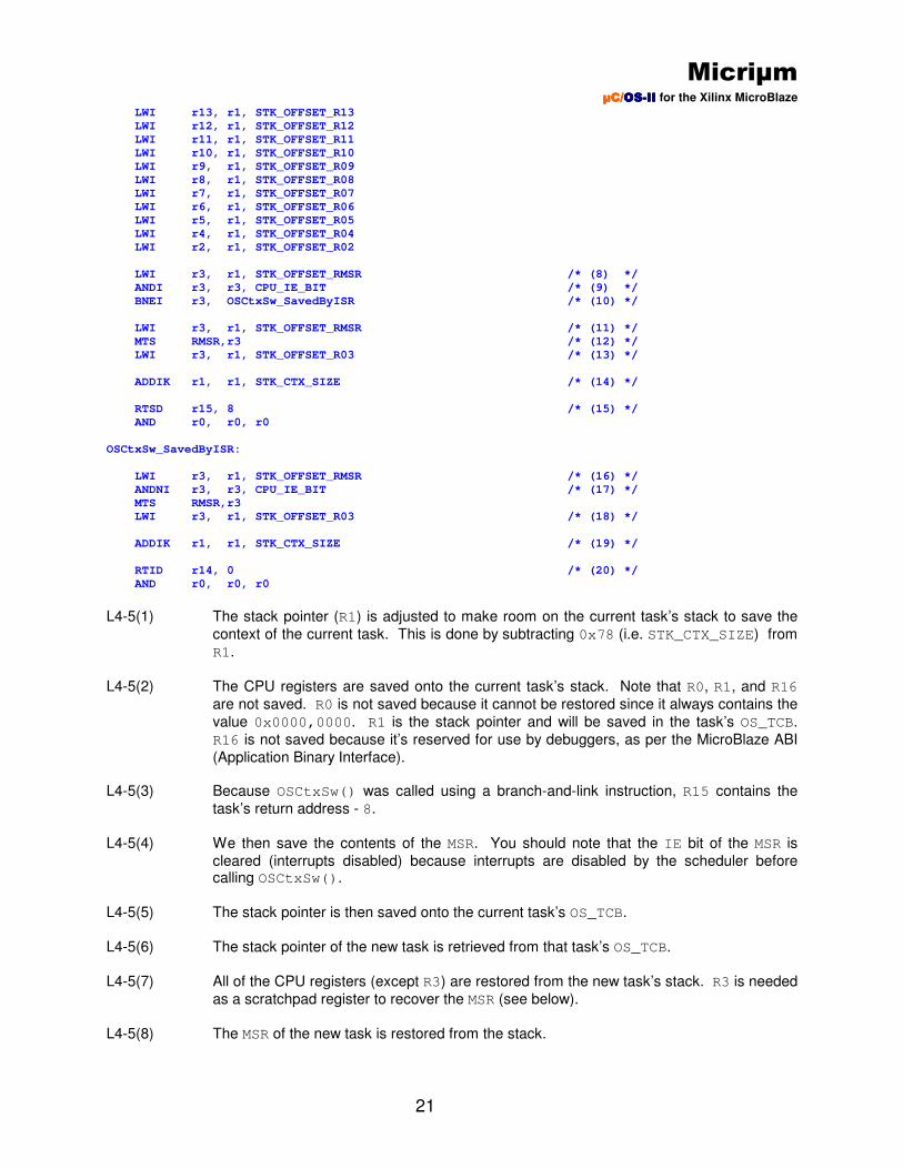
L4-5(1) The stack pointer (R1) is adjusted to make room on the current task’s stack to save the
context of the current task. This is done by subtracting 0x78 (i.e. STK_CTX_SIZE) from
R1.
L4-5(2) The CPU registers are saved onto the current task’s stack. Note that R0, R1, and R16
are not saved. R0 is not saved because it cannot be restored since it always contains the
value 0x0000,0000. R1 is the stack pointer and will be saved in the task’s OS_TCB.
R16 is not saved because it’s reserved for use by debuggers, as per the MicroBlaze ABI
(Application Binary Interface). L4-5(3) Because OSCtxSw() was called using a branch-and-link instruction, R15 contains the
task’s return address - 8.
L4-5(4) We then save the contents of the MSR. You should note that the IE bit of the MSR is
cleared (interrupts disabled) because interrupts are disabled by the scheduler before calling OSCtxSw().
L4-5(5) The stack pointer is then saved onto the current task’s OS_TCB.
L4-5(6) The stack pointer of the new task is retrieved from that task’s OS_TCB.
L4-5(7) All of the CPU registers (except R3) are restored from the new task’s stack. R3 is needed
as a scratchpad register to recover the MSR (see below).
L4-5(8) The MSR of the new task is restored from the stack.
Micriµm µC/µC/µC/µC/OSOSOSOS----IIIIIIII for the Xilinx MicroBlaze
22
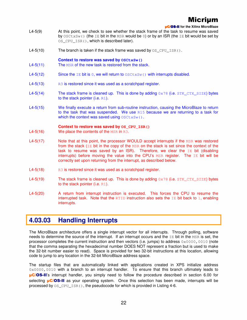
L4-5(9) At this point, we check to see whether the stack frame of the task to resume was saved by OSCtxSw() (the IE bit in the MSR would be 0) or by an ISR (the IE bit would be set by
OS_CPU_ISR(), which is described later).
L4-5(10) The branch is taken if the stack frame was saved by OS_CPU_ISR().
Context to restore was saved by OSCtxSw()
L4-5(11) The MSR of the new task is restored from the stack.
L4-5(12) Since the IE bit is 0, we will return to OSCtxSw() with interrupts disabled.
L4-5(13) R3 is restored since it was used as a scratchpad register.
L4-5(14) The stack frame is cleaned up. This is done by adding 0x78 (i.e. STK_CTX_SIZE) bytes
to the stack pointer (i.e. R1).
L4-5(15) We finally execute a return from sub-routine instruction, causing the MicroBlaze to return
to the task that was suspended. We use R15 because we are returning to a task for
which the context was saved using OSCtxSw().
Context to restore was saved by OS_CPU_ISR()
L4-5(16) We place the contents of the MSR in R3.
L4-5(17) Note that at this point, the processor WOULD accept interrupts if the MSR was restored
from the stack (IE bit in the copy of the MSR on the stack is set since the context of the
task to resume was saved by an ISR). Therefore, we clear the IE bit (disabling
interrupts) before moving the value into the CPU’s MSR register. The IE bit will be
correctly set upon returning from the interrupt, as described below. L4-5(18) R3 is restored since it was used as a scratchpad register.
L4-5(19) The stack frame is cleaned up. This is done by adding 0x78 (i.e. STK_CTX_SIZE) bytes
to the stack pointer (i.e. R1).
L4-5(20) A return from interrupt instruction is executed. This forces the CPU to resume the
interrupted task. Note that the RTID instruction also sets the IE bit back to 1, enabling
interrupts.
4.03.03 Handling Interrupts The MicroBlaze architecture offers a single interrupt vector for all interrupts. Through polling, software needs to determine the source of the interrupt. If an interrupt occurs and the IE bit in the MSR is set, the
processor completes the current instruction and then vectors (i.e. jumps) to address 0x0000,0010 (note
that the comma separating the hexadecimal number DOES NOT represent a fraction but is used to make the 32-bit number easier to read). Space is provided for two 32-bit instructions at this location, allowing code to jump to any location in the 32-bit MicroBlaze address space. The startup files that are automatically linked with applications created in XPS initialize address 0x0000,0010 with a branch to an interrupt handler. To ensure that this branch ultimately leads to
µC/OS-II’s interrupt handler, you simply need to follow the procedure described in section 6.00 for
selecting µC/OS-II as your operating system. Once this selection has been made, interrupts will be
processed by OS_CPU_ISR(), the pseudocode for which is provided in Listing 4-6.
Micriµm µC/µC/µC/µC/OSOSOSOS----IIIIIIII for the Xilinx MicroBlaze
23
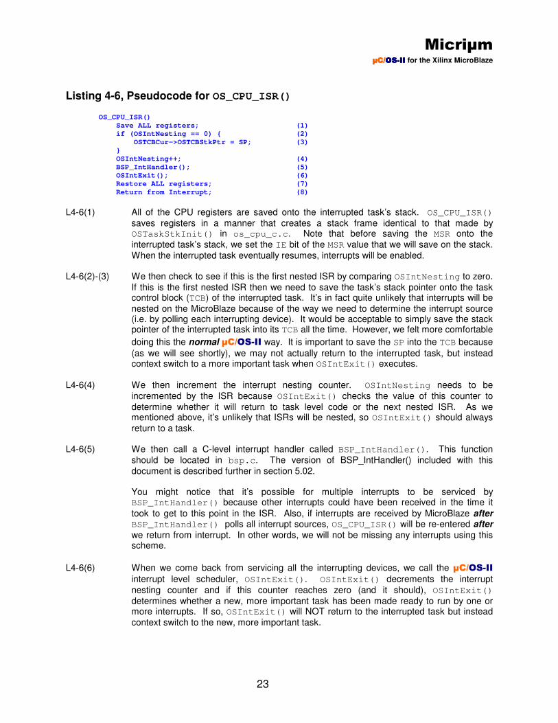
Listing 4-6, Pseudocode for OS_CPU_ISR()
OS_CPU_ISR()
Save ALL registers; (1)
if (OSIntNesting == 0) { (2)
OSTCBCur->OSTCBStkPtr = SP; (3)
}
OSIntNesting++; (4)
BSP_IntHandler(); (5)
OSIntExit(); (6)
Restore ALL registers; (7)
Return from Interrupt; (8)
L4-6(1) All of the CPU registers are saved onto the interrupted task’s stack. OS_CPU_ISR()
saves registers in a manner that creates a stack frame identical to that made by OSTaskStkInit() in os_cpu_c.c. Note that before saving the MSR onto the
interrupted task’s stack, we set the IE bit of the MSR value that we will save on the stack.
When the interrupted task eventually resumes, interrupts will be enabled. L4-6(2)-(3) We then check to see if this is the first nested ISR by comparing OSIntNesting to zero.
If this is the first nested ISR then we need to save the task’s stack pointer onto the task control block (TCB) of the interrupted task. It’s in fact quite unlikely that interrupts will be
nested on the MicroBlaze because of the way we need to determine the interrupt source (i.e. by polling each interrupting device). It would be acceptable to simply save the stack pointer of the interrupted task into its TCB all the time. However, we felt more comfortable
doing this the normal µC/OS-II way. It is important to save the SP into the TCB because
(as we will see shortly), we may not actually return to the interrupted task, but instead context switch to a more important task when OSIntExit() executes.
L4-6(4) We then increment the interrupt nesting counter. OSIntNesting needs to be
incremented by the ISR because OSIntExit() checks the value of this counter to
determine whether it will return to task level code or the next nested ISR. As we mentioned above, it’s unlikely that ISRs will be nested, so OSIntExit() should always
return to a task. L4-6(5) We then call a C-level interrupt handler called BSP_IntHandler(). This function
should be located in bsp.c. The version of BSP_IntHandler() included with this
document is described further in section 5.02.
You might notice that it’s possible for multiple interrupts to be serviced by BSP_IntHandler() because other interrupts could have been received in the time it
took to get to this point in the ISR. Also, if interrupts are received by MicroBlaze after BSP_IntHandler() polls all interrupt sources, OS_CPU_ISR() will be re-entered after
we return from interrupt. In other words, we will not be missing any interrupts using this scheme.
L4-6(6) When we come back from servicing all the interrupting devices, we call the µC/OS-II
interrupt level scheduler, OSIntExit(). OSIntExit() decrements the interrupt
nesting counter and if this counter reaches zero (and it should), OSIntExit()
determines whether a new, more important task has been made ready to run by one or more interrupts. If so, OSIntExit() will NOT return to the interrupted task but instead
context switch to the new, more important task.

Micriµm µC/µC/µC/µC/OSOSOSOS----IIIIIIII for the Xilinx MicroBlaze
24
L4-6(7)-(8) If the interrupted task is still the most important task after servicing the interrupt, then OSIntExit() returns, resulting in a return to that task (blue path in Figure 4-3). If a
more important task has been made ready to run by one or more interrupting devices, then OSIntExit() resumes the higher priority task (red path in Figure 4-3).
Figure 4-3, Servicing Interrupts with OS_CPU_ISR()
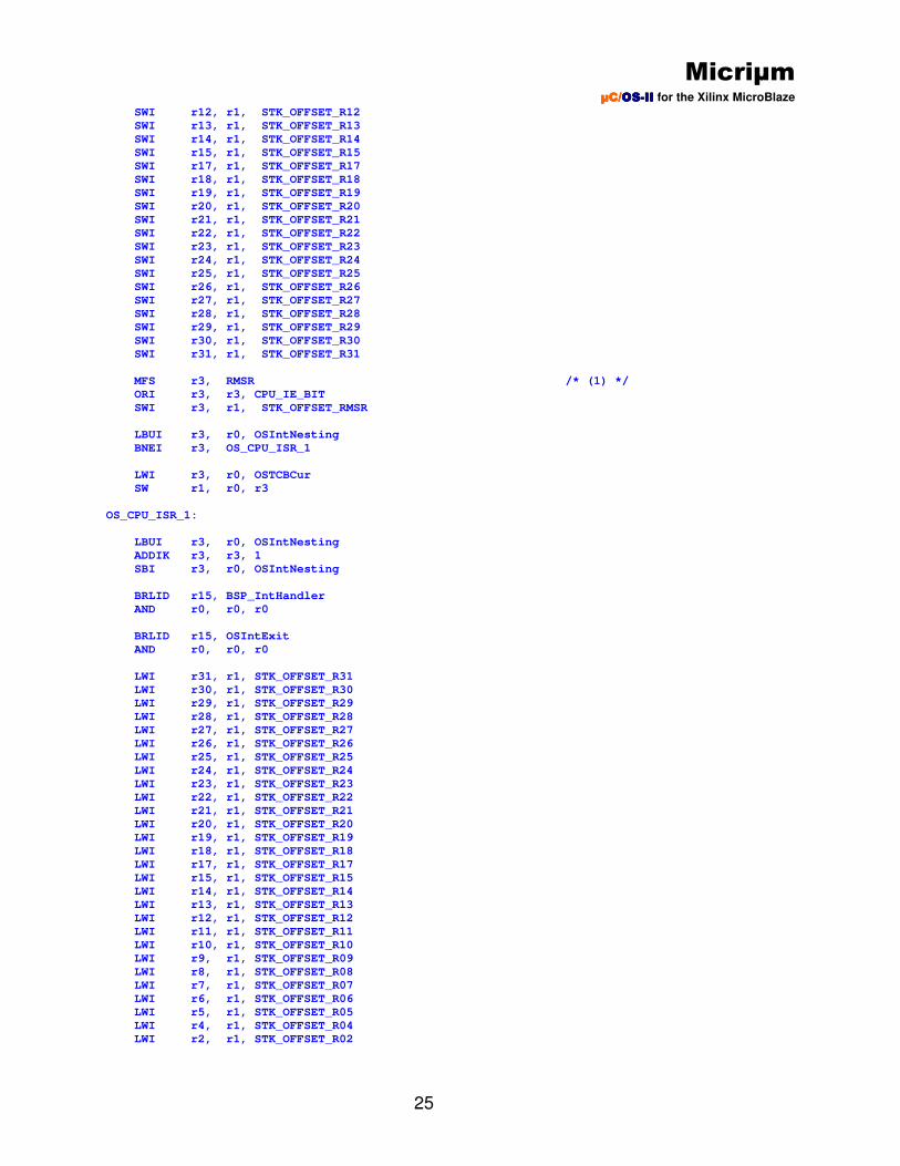
4.03.04 os_cpu_a.s, OS_CPU_ISR() The actual code to implement OS_CPU_ISR() is shown in Listing 4-7 and follows the pseudocode
presented in the previous section.
Listing 4-7, OS_CPU_ISR() OS_CPU_ISR:
ADDIK r1, r1, -STK_CTX_SIZE
SWI r2, r1, STK_OFFSET_R02
SWI r3, r1, STK_OFFSET_R03
SWI r4, r1, STK_OFFSET_R04
SWI r5, r1, STK_OFFSET_R05
SWI r6, r1, STK_OFFSET_R06
SWI r7, r1, STK_OFFSET_R07
SWI r8, r1, STK_OFFSET_R08
SWI r9, r1, STK_OFFSET_R09
SWI r10, r1, STK_OFFSET_R10
SWI r11, r1, STK_OFFSET_R11
Task Code
Gets
Interrupted
OS_CPU_ISR: Save ALL registers; (Set IE to 1 on the stack frame) if (OSIntNesting == 0) { OSTCBCur->OSTCBStkPtr = SP; } OSIntNesting++;
BSP_IntHandler();
OSIntExit();
Restore ALL registers; Return from Interrupt;
IE=0
BSP_IntHandler() Determine source of Interrupt(s);
Service ALL interrupts!
Return;
IE=1
Interrupted
Task Code
Resumed
High
Priority
Task
Suspended
High
Priority
Task
Resumed
Task Code Suspended
IE=1
IE=1
OSIntExit() if (Higher priority task Ready) Restore ALL registers; Return from Interrupt; else
Micriµm µC/µC/µC/µC/OSOSOSOS----IIIIIIII for the Xilinx MicroBlaze
25
SWI r12, r1, STK_OFFSET_R12
SWI r13, r1, STK_OFFSET_R13
SWI r14, r1, STK_OFFSET_R14
SWI r15, r1, STK_OFFSET_R15
SWI r17, r1, STK_OFFSET_R17
SWI r18, r1, STK_OFFSET_R18
SWI r19, r1, STK_OFFSET_R19
SWI r20, r1, STK_OFFSET_R20
SWI r21, r1, STK_OFFSET_R21
SWI r22, r1, STK_OFFSET_R22
SWI r23, r1, STK_OFFSET_R23
SWI r24, r1, STK_OFFSET_R24
SWI r25, r1, STK_OFFSET_R25
SWI r26, r1, STK_OFFSET_R26
SWI r27, r1, STK_OFFSET_R27
SWI r28, r1, STK_OFFSET_R28
SWI r29, r1, STK_OFFSET_R29
SWI r30, r1, STK_OFFSET_R30
SWI r31, r1, STK_OFFSET_R31
MFS r3, RMSR /* (1) */
ORI r3, r3, CPU_IE_BIT
SWI r3, r1, STK_OFFSET_RMSR
LBUI r3, r0, OSIntNesting
BNEI r3, OS_CPU_ISR_1
LWI r3, r0, OSTCBCur
SW r1, r0, r3
OS_CPU_ISR_1:
LBUI r3, r0, OSIntNesting
ADDIK r3, r3, 1
SBI r3, r0, OSIntNesting
BRLID r15, BSP_IntHandler
AND r0, r0, r0
BRLID r15, OSIntExit
AND r0, r0, r0
LWI r31, r1, STK_OFFSET_R31
LWI r30, r1, STK_OFFSET_R30
LWI r29, r1, STK_OFFSET_R29
LWI r28, r1, STK_OFFSET_R28
LWI r27, r1, STK_OFFSET_R27
LWI r26, r1, STK_OFFSET_R26
LWI r25, r1, STK_OFFSET_R25
LWI r24, r1, STK_OFFSET_R24
LWI r23, r1, STK_OFFSET_R23
LWI r22, r1, STK_OFFSET_R22
LWI r21, r1, STK_OFFSET_R21
LWI r20, r1, STK_OFFSET_R20
LWI r19, r1, STK_OFFSET_R19
LWI r18, r1, STK_OFFSET_R18
LWI r17, r1, STK_OFFSET_R17
LWI r15, r1, STK_OFFSET_R15
LWI r14, r1, STK_OFFSET_R14
LWI r13, r1, STK_OFFSET_R13
LWI r12, r1, STK_OFFSET_R12
LWI r11, r1, STK_OFFSET_R11
LWI r10, r1, STK_OFFSET_R10
LWI r9, r1, STK_OFFSET_R09
LWI r8, r1, STK_OFFSET_R08
LWI r7, r1, STK_OFFSET_R07
LWI r6, r1, STK_OFFSET_R06
LWI r5, r1, STK_OFFSET_R05
LWI r4, r1, STK_OFFSET_R04
LWI r2, r1, STK_OFFSET_R02
Micriµm µC/µC/µC/µC/OSOSOSOS----IIIIIIII for the Xilinx MicroBlaze
26
LWI r3, r1, STK_OFFSET_RMSR /* (2) */
ANDNI r3, r3, CPU_IE_BIT /* (3) */
MTS RMSR,r3
LWI r3, r1, STK_OFFSET_R03 /* (4) */
ADDIK r1, r1, STK_CTX_SIZE /* (5) */
RTID r14, 0
AND r0, r0, r0
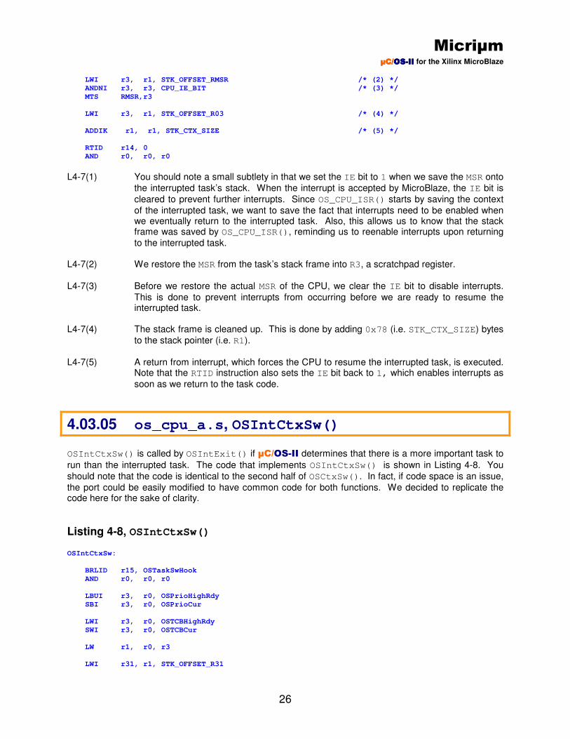
L4-7(1) You should note a small subtlety in that we set the IE bit to 1 when we save the MSR onto
the interrupted task’s stack. When the interrupt is accepted by MicroBlaze, the IE bit is
cleared to prevent further interrupts. Since OS_CPU_ISR() starts by saving the context
of the interrupted task, we want to save the fact that interrupts need to be enabled when we eventually return to the interrupted task. Also, this allows us to know that the stack frame was saved by OS_CPU_ISR(), reminding us to reenable interrupts upon returning
to the interrupted task. L4-7(2) We restore the MSR from the task’s stack frame into R3, a scratchpad register.
L4-7(3) Before we restore the actual MSR of the CPU, we clear the IE bit to disable interrupts.
This is done to prevent interrupts from occurring before we are ready to resume the interrupted task.
L4-7(4) The stack frame is cleaned up. This is done by adding 0x78 (i.e. STK_CTX_SIZE) bytes
to the stack pointer (i.e. R1).
L4-7(5) A return from interrupt, which forces the CPU to resume the interrupted task, is executed.
Note that the RTID instruction also sets the IE bit back to 1, which enables interrupts as
soon as we return to the task code.
4.03.05 os_cpu_a.s, OSIntCtxSw()
OSIntCtxSw() is called by OSIntExit() if µC/OS-II determines that there is a more important task to
run than the interrupted task. The code that implements OSIntCtxSw() is shown in Listing 4-8. You
should note that the code is identical to the second half of OSCtxSw(). In fact, if code space is an issue,
the port could be easily modified to have common code for both functions. We decided to replicate the code here for the sake of clarity.
Listing 4-8, OSIntCtxSw() OSIntCtxSw:
BRLID r15, OSTaskSwHook
AND r0, r0, r0
LBUI r3, r0, OSPrioHighRdy
SBI r3, r0, OSPrioCur
LWI r3, r0, OSTCBHighRdy
SWI r3, r0, OSTCBCur
LW r1, r0, r3
LWI r31, r1, STK_OFFSET_R31

Micriµm µC/µC/µC/µC/OSOSOSOS----IIIIIIII for the Xilinx MicroBlaze
27
LWI r30, r1, STK_OFFSET_R30
LWI r29, r1, STK_OFFSET_R29
LWI r28, r1, STK_OFFSET_R28
LWI r27, r1, STK_OFFSET_R27
LWI r26, r1, STK_OFFSET_R26
LWI r25, r1, STK_OFFSET_R25
LWI r24, r1, STK_OFFSET_R24
LWI r23, r1, STK_OFFSET_R23
LWI r22, r1, STK_OFFSET_R22
LWI r21, r1, STK_OFFSET_R21
LWI r20, r1, STK_OFFSET_R20
LWI r19, r1, STK_OFFSET_R19
LWI r18, r1, STK_OFFSET_R18
LWI r17, r1, STK_OFFSET_R17
LWI r15, r1, STK_OFFSET_R15
LWI r14, r1, STK_OFFSET_R14
LWI r13, r1, STK_OFFSET_R13
LWI r12, r1, STK_OFFSET_R12
LWI r11, r1, STK_OFFSET_R11
LWI r10, r1, STK_OFFSET_R10
LWI r9, r1, STK_OFFSET_R09
LWI r8, r1, STK_OFFSET_R08
LWI r7, r1, STK_OFFSET_R07
LWI r6, r1, STK_OFFSET_R06
LWI r5, r1, STK_OFFSET_R05
LWI r4, r1, STK_OFFSET_R04
LWI r2, r1, STK_OFFSET_R02
LWI r3, r1, STK_OFFSET_RMSR
ANDI r3, r3, CPU_IE_BIT
BNEI r3, OSIntCtxSw_SavedByISR
LWI r3, r1, STK_OFFSET_RMSR
MTS RMSR,r3
LWI r3, r1, STK_OFFSET_R03
ADDIK r1, r1, STK_CTX_SIZE
RTSD r15, 8
AND r0, r0, r0
OSIntCtxSw_SavedByISR:
LWI r3, r1, STK_OFFSET_RMSR
ANDNI r3, r3, CPU_IE_BIT
MTS RMSR,r3
LWI r3, r1, STK_OFFSET_R03
ADDIK r1, r1, STK_CTX_SIZE
RTID r14, 0
AND r0, r0, r0
4.03.06 os_cpu_a.s, OS_CPU_SR_Save() OS_CPU_SR_Save() is responsible for saving the MSR and disabling interrupts, as per the requirements
of OS_CRITICAL_METHOD #3. When this function returns, R3 contains the state of the MSR prior to
disabling interrupts. The µC/OS-II MicroBlaze port actually provides two implementations of
OS_CPU_SR_Save(), the simpler of which is shown in Listing 4-9. Although this version of the function is
more concise, it utilizes the MSRCLR instruction, which is not recognized by all MicroBlaze processors.
Thus, a second, slightly larger version of OS_CPU_SR_Save() is also provided. This version can be seen
in Listing 4-10. When your application is built, the Tcl file provided with the µC/OS-II MicroBlaze port
actually decides which version of the function should be used.

Micriµm µC/µC/µC/µC/OSOSOSOS----IIIIIIII for the Xilinx MicroBlaze
28
Listing 4-9, OS_CPU_SR_Save() OS_CPU_SR_Save:
RTSD r15, 8
MSRCLR r3, CPU_IE_BIT
Listing 4-10, Alternate OS_CPU_SR_Save() OS_CPU_SR_Save:
ADDIK r1, r1, -4
SW r4, r1, r0
MFS r3, RMSR
ANDNI r4, r3, CPU_IE_BIT
MTS RMSR, r4
LW r4, r1, r0
ADDIK r1, r1, 4
AND r0, r0, r0
AND r0, r0, r0
AND r0, r0, r0
RTSD r15, 8
AND r0, r0, r0
4.03.07 os_cpu_a.s, OS_CPU_SR_Restore() The code in the listing below implements the function that restores the MSR register for
OS_CRITICAL_METHOD #3. When the function is called, it’s assumed that R5 contains the desired state
of the MSR register.
Listing 4-11, OS_CPU_SR_Restore() OS_CPU_SR_Restore
RTSD r15, 8
MTS rMSR, r5
4.04 os_dbg.c
os_dbg.c is a file that was added in V2.62 to allow Kernel Aware debuggers to extract information about
µC/OS-II and its configuration. Specifically, os_dbg.c contains a number of constants that are placed in
ROM (code space). These constants can be read and displayed by the debugger. This file is not actually used in the MicroBlaze port since Kernel Awareness is not supported by the debugger.
Micriµm µC/µC/µC/µC/OSOSOSOS----IIIIIIII for the Xilinx MicroBlaze
29
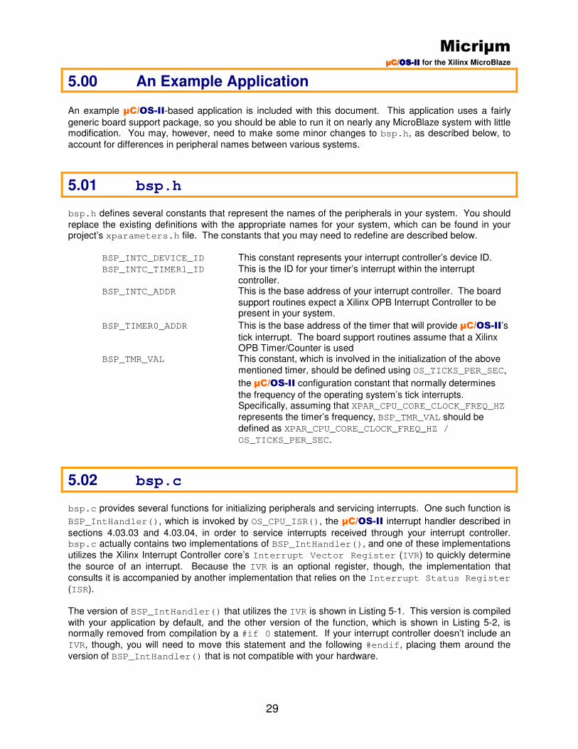
5.00 An Example Application
An example µC/OS-II-based application is included with this document. This application uses a fairly
generic board support package, so you should be able to run it on nearly any MicroBlaze system with little modification. You may, however, need to make some minor changes to bsp.h, as described below, to
account for differences in peripheral names between various systems.
5.01 bsp.h
bsp.h defines several constants that represent the names of the peripherals in your system. You should
replace the existing definitions with the appropriate names for your system, which can be found in your project’s xparameters.h file. The constants that you may need to redefine are described below.
BSP_INTC_DEVICE_ID This constant represents your interrupt controller’s device ID.
BSP_INTC_TIMER1_ID This is the ID for your timer’s interrupt within the interrupt
controller. BSP_INTC_ADDR This is the base address of your interrupt controller. The board
support routines expect a Xilinx OPB Interrupt Controller to be present in your system.
BSP_TIMER0_ADDR This is the base address of the timer that will provide µC/OS-II’s
tick interrupt. The board support routines assume that a Xilinx OPB Timer/Counter is used
BSP_TMR_VAL This constant, which is involved in the initialization of the above
mentioned timer, should be defined using OS_TICKS_PER_SEC,
the µC/OS-II configuration constant that normally determines
the frequency of the operating system’s tick interrupts. Specifically, assuming that XPAR_CPU_CORE_CLOCK_FREQ_HZ
represents the timer’s frequency, BSP_TMR_VAL should be
defined as XPAR_CPU_CORE_CLOCK_FREQ_HZ /
OS_TICKS_PER_SEC.
5.02 bsp.c
bsp.c provides several functions for initializing peripherals and servicing interrupts. One such function is
BSP_IntHandler(), which is invoked by OS_CPU_ISR(), the µC/OS-II interrupt handler described in
sections 4.03.03 and 4.03.04, in order to service interrupts received through your interrupt controller. bsp.c actually contains two implementations of BSP_IntHandler(), and one of these implementations
utilizes the Xilinx Interrupt Controller core’s Interrupt Vector Register (IVR) to quickly determine
the source of an interrupt. Because the IVR is an optional register, though, the implementation that
consults it is accompanied by another implementation that relies on the Interrupt Status Register
(ISR).
The version of BSP_IntHandler() that utilizes the IVR is shown in Listing 5-1. This version is compiled
with your application by default, and the other version of the function, which is shown in Listing 5-2, is normally removed from compilation by a #if 0 statement. If your interrupt controller doesn’t include an
IVR, though, you will need to move this statement and the following #endif, placing them around the
version of BSP_IntHandler() that is not compatible with your hardware.

Micriµm µC/µC/µC/µC/OSOSOSOS----IIIIIIII for the Xilinx MicroBlaze
30
Listing 5-1, BSP_IntHandler() void BSP_IntHandler (void)
{
INT32U int_status;
INT32U int_mask;
INT32U int_vector;
XIntc_Config *CfgPtr;
XIntc_VectorTableEntry *tbl_ptr;
CfgPtr = &XIntc_ConfigTable[0];
int_status = XIntc_mGetIntrStatus(BSP_INTC_ADDR);
while (int_status != 0) {
int_vector = *(INT32U *)(BSP_INTC_ADDR + 0x00000018);
int_mask = 1 << int_vector;
if (((CfgPtr->AckBeforeService) & int_mask) != 0) {
XIntc_mAckIntr(BSP_INTC_ADDR, int_mask);
}
tbl_ptr = &(CfgPtr->HandlerTable[int_vector]);
tbl_ptr->Handler(tbl_ptr->CallBackRef);
if (((CfgPtr->AckBeforeService) & int_mask) == 0) {
XIntc_mAckIntr(BSP_INTC_ADDR, int_mask);
}
int_status = XIntc_mGetIntrStatus(BSP_INTC_ADDR);
}
}
Listing 5-2, Alternate BSP_IntHandler() void BSP_IntHandler (void)
{
Xuint32 IntrStatus;
Xuint32 IntrMask = 1;
int IntrNumber;
XIntc_Config *CfgPtr;
CfgPtr = &XIntc_ConfigTable[(Xuint32)BSP_INTC_DEVICE_ID];
IntrStatus = XIntc_mGetIntrStatus(CfgPtr->BaseAddress);
for (IntrNumber = 0; IntrNumber < XPAR_INTC_MAX_NUM_INTR_INPUTS; IntrNumber++) {
if (IntrStatus & 1) {
XIntc_VectorTableEntry *TablePtr;
if (CfgPtr->AckBeforeService & IntrMask) {
XIntc_mAckIntr(CfgPtr->BaseAddress, IntrMask);
}
TablePtr = &(CfgPtr->HandlerTable[IntrNumber]);
TablePtr->Handler(TablePtr->CallBackRef);
if ((CfgPtr->AckBeforeService & IntrMask) == 0) {
XIntc_mAckIntr(CfgPtr->BaseAddress, IntrMask);
}
if (CfgPtr->Options == XIN_SVC_SGL_ISR_OPTION) {
return;
}
}
IntrMask <<= 1;
IntrStatus >>= 1;
if (IntrStatus == 0){
break;
}
}
}

Micriµm µC/µC/µC/µC/OSOSOSOS----IIIIIIII for the Xilinx MicroBlaze
31
5.03 helloworld.c
helloworld.c is a simple application that you can use to verify your µC/OS-II and BSP setup. You
may wish to use this application as a starting point for your own µC/OS-II-based applications on your
MicroBlaze system. The code in helloworld.c is described in Listing 5-3, Listing 5-4, Listing 5-5, and
Listing 5-6.
Listing 5-3, helloworld.c, main() int main (void)
{
CPU_INT8U err;
BSP_IntDisAll(); /* (1) */
OSInit(); /* (2) */
OSTaskCreateExt(FirstTask, /* (3) */
(void *)0,
&FirstTaskStk[TASK_STK_SIZE – 1],
TASK1_ID,
TASK1_PRIO,
&FirstTaskStk[0]
TASK_STK_SIZE,
(void *)0,
OS_TASK_OPT_STK_CHK | OS_TASK_OPT_STK_CLR);
OSTaskNameSet(APP_TASK_FIRST_PRIO, “App Task First”, &err); /* (4) */
OSStart(); /* (5) */
return 0; /* (6) */
}
L5-3(1) BSP_IntDisAll(), which is declared in bsp.c, is used to make sure that the interrupt
controller does not allow any interrupts until we are ready.
L5-3(2) OSInit() must be called to initialize µC/OS-II before you actually use any of the other
services (i.e. functions) provided by the operating system. L5-3(3) OSTaskCreateExt() creates a single application task called FirstTask(). This task will
be described later. L5-3(4) OSTaskNameSet() provides a means of assigning a name to each task in the application.
Task names can be used during debugging. Names can only be assigned to tasks that have been created using OSTaskCreateExt().
L5-3(5) OSStart() is called to give control to µC/OS-II and start multitasking. OSStart() finds
the highest priority task of all the tasks created (in this case, it’s AppTaskFirst()) and
starts executing that task. OSStart() never returns.
L5-3(6) Return 0 so that the compiler does not throw any warnings about no valid returns.
Listing 5-4, helloworld.c, FirstTask()

Micriµm µC/µC/µC/µC/OSOSOSOS----IIIIIIII for the Xilinx MicroBlaze
32
static void FirstTask (void *p_arg)
{
p_arg = p_arg;
BSP_InitIO(); /* (1) */
#if OS_TASK_STAT_EN > 0
OSStatInit(); /* (2) */
#endif
AppTaskCreate(); /* (3) */
while (1) {
printf(“First task says Hello World\n”); /* (4) */
OSTimeDlyHMSM(0,0,3,0);
}
}
L5-4(1) FirstTask() calls BSP_InitIO() to initialize the I/O devices, which in this case consist of
an interrupt controller, a timer/counter, and a GPIO core. The initializations for the interrupt controller involve enabling the timer interrupt and specifying a handler for this interrupt. The timer is set up to cause an interrupt at a frequency of OS_TICKS_PER_SEC, a value which
can be adjusted using the Board Support Package Settings dialog box described in the next section.
L5-4(2) OSStatInit() is called to initialize a statistics task, which will determine the percentage of
CPU time that is being used by your application. OSStatInit() should only be called if
OS_TASK_STAT_EN, which can be set through the Board Support Package Settings dialog
box, has a value of 1. Additionally, OSStatInit() must be called after BSP_InitIO(),
because it depends on the tick interrupt enabled by that function. Further information about OSStatInit() and the methods that it uses to compute CPU usage can be found in the
µC/OS-II book (see References, at the end of this application note).
L5-4(3) AppTaskCreate () is a separate function to create all the other tasks after the first one.
L5-4(4) In µC/OS-II-based applications, the body of each task is an infinite loop. FirstTask()
simply prints a message within this loop, indicating that everything is running properly.
Listing 5-5, helloworld.c, SecondTask() static void SecondTask (void *p_arg)
{
p_arg = p_arg;
while (1) {
printf(“Second task says Hello World\n”); /* (1) */
OSTimeDlyHMSM(0,0,3,0);
}
}
L5-5(1) In µC/OS-II-based applications, the body of each task is an infinite loop. SecondTask()
simply prints a message within this loop, indicating that everything is running properly.
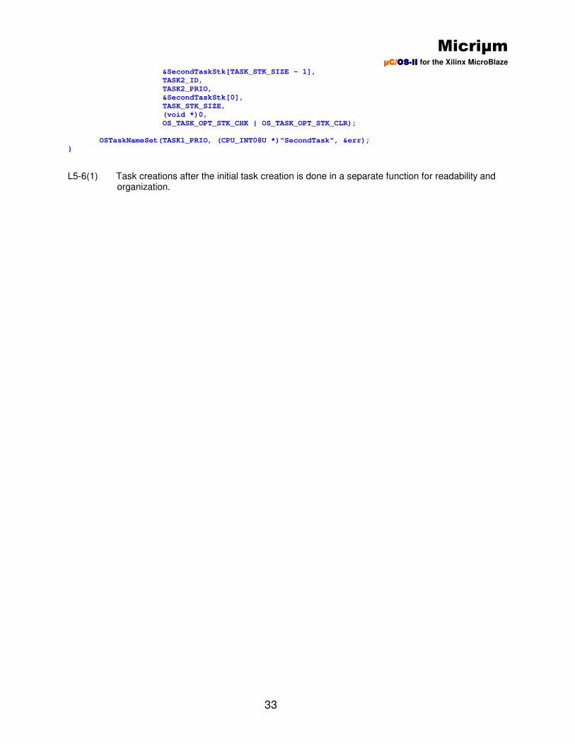
Listing 5-6, helloworld.c, AppTaskCreate() static void AppTaskCreate (void)
{
CPU_INT08U err;
OSTaskCreateExt(SecondTask, /* (1) */
(void *)0,
Micriµm µC/µC/µC/µC/OSOSOSOS----IIIIIIII for the Xilinx MicroBlaze
33
&SecondTaskStk[TASK_STK_SIZE - 1],
TASK2_ID,
TASK2_PRIO,
&SecondTaskStk[0],
TASK_STK_SIZE,
(void *)0,
OS_TASK_OPT_STK_CHK | OS_TASK_OPT_STK_CLR);
OSTaskNameSet(TASK1_PRIO, (CPU_INT08U *)"SecondTask", &err);
}
L5-6(1) Task creations after the initial task creation is done in a separate function for readability and organization.
Micriµm µC/µC/µC/µC/OSOSOSOS----IIIIIIII for the Xilinx MicroBlaze
34
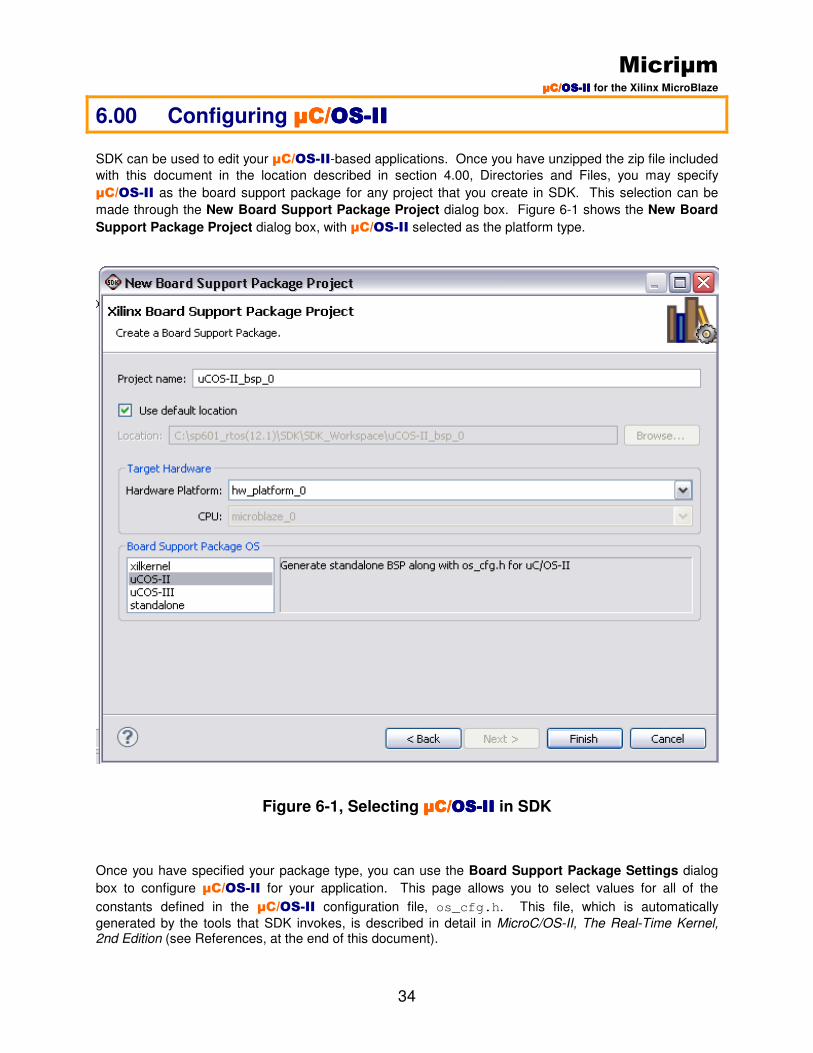
6.00 Configuring µC/µC/µC/µC/OSOSOSOS----IIIIIIII
SDK can be used to edit your µC/OS-II-based applications. Once you have unzipped the zip file included
with this document in the location described in section 4.00, Directories and Files, you may specify
µC/OS-II as the board support package for any project that you create in SDK. This selection can be
made through the New Board Support Package Project dialog box. Figure 6-1 shows the New Board
Support Package Project dialog box, with µC/OS-II selected as the platform type.
Figure 6-1, Selecting µC/µC/µC/µC/OSOSOSOS----IIIIIIII in SDK
Once you have specified your package type, you can use the Board Support Package Settings dialog
box to configure µC/OS-II for your application. This page allows you to select values for all of the
constants defined in the µC/OS-II configuration file, os_cfg.h. This file, which is automatically
generated by the tools that SDK invokes, is described in detail in MicroC/OS-II, The Real-Time Kernel,
2nd Edition (see References, at the end of this document).

Micriµm µC/µC/µC/µC/OSOSOSOS----IIIIIIII for the Xilinx MicroBlaze
35
In addition to providing a means of assigning values to µC/OS-II configuration constants, the uC-OSII
page allows you to specify the location of your µC/OS-II source files. If µC/OS-II is selected as your
operating system, these files should be located in the folders described in section 4.00, Directories and Files. If you did not place the files in these locations, however, you will need to use the FILE_LOCATION parameters, which can be seen in Figure 6-2, to specify the location of the files. You should also be
aware of the fact that if you have not purchased µC/Probe, and, consequently, you do not have
µC/Probe source files, you should select a value of 0 for the uC-Probe parameters PROBE_EN, and
PROBE_OS_EN so these files will be ignored.
Figure 6-2, Modifying the Default File Locations

Micriµm µC/µC/µC/µC/OSOSOSOS----IIIIIIII for the Xilinx MicroBlaze
36
7.00 Running the Example Application After you have made any needed changes to the BSP files, you can use the included sample application to check that these files are correctly accessing your hardware. First, however, you should make sure that
you have completed the steps listed in section 3.00, Using the µC/OS-II MicroBlaze Port. After these
steps have been taken, you should create a new project on top of your µC/OS-II platform by creating a
new Xilinx C Project, and then creating the uC_OS-II Hello World application. You then have the option
of creating the µC/OS-II BSP along with the application or choose the BSP as an exsisting one if it has
already been created. After the application is created, the entry for your software project in the projects tab of SDK should resemble that shown in Figure 7-1.
Figure 7-1, Example Application
Once µC/OS-II has been chosen as your BSP, you should be able to build and run the example
application. This process is somewhat project-specific, so you should follow the steps that you normally take to download a software application. If the application is running correctly, you should see both hello
world messages print out on the stdout peripheral that is designated to the µC/OS-II bsp. By default this
should be your RS232 UART device but it can be changed in the the µC/OS-II board support package
settings. If the messages are not displaying, you may need to look over section 3.00, Using the µC/OS-II
MicroBlaze Port, and make sure that you have taken all the steps needed to use the port. You may also want to review section 5.01, bsp.h, and verify that the values specified for the constants in that file indeed
match those defined for your system in xparameters.h.
Micriµm µC/µC/µC/µC/OSOSOSOS----IIIIIIII for the Xilinx MicroBlaze
37
Licensing
µC/OS-II source and object code can be used by accredited Colleges and Universities without requiring a
license, as long as there is no commercial application involved. In other words, no licensing is required if
µC/OS-II is used for educational purposes.
You need to obtain an 'Object Code Distribution License' to embed µC/OS-II in a product that is sold with
the intent to make a profit or if the product is not used for education or 'peaceful' research. For additional details, contact us at [email protected] or by calling us (see Contacts).
Acknowledgements
We would like to thank the following people for their support in making the µC/OS-II MicroBlaze port
possible:
Xilinx: Mr. Jim Burnham Mr. Goran Bilski, the designer of the MicroBlaze.
Memec: Mr. Jim Beneke who is responsible for Memec’s worldwide Xilinx technical marketing activities. Mr. Bryan Fletcher who is responsible for Spartan and MicroBlaze marketing programs, general hardware tools technical support. Mr. Nasser Poureh who is responsible for Virtex-II Pro and PowerPC marketing programs and general hardware tools technical support. Mr. Poureh has been especially helpful and patient in getting us up and running on the Xilinx tools. Mr. Ron Wright who is responsible for software applications on MicroBlaze and PowerPC and general software tools technical support.
References MicroC/OS-II, The Real-Time Kernel, 2
nd Edition
Jean J. Labrosse R&D Technical Books, 2002 ISBN 1-5782-0103-9

Micriµm µC/µC/µC/µC/OSOSOSOS----IIIIIIII for the Xilinx MicroBlaze
38
Contacts Micriµm 1290 Weston Road, Suite 306 Weston, FL 33326 USA +1 954 217 2036 +1 954 217 2037 (FAX) e-mail: [email protected] WEB: www.Micrium.com CMP Books, Inc. 1601 W. 23rd St., Suite 200 Lawrence, KS 66046-9950 USA +1 785 841 1631 +1 785 841 2624 (FAX) WEB: http://www.rdbooks.com e-mail: [email protected] Xilinx Inc. 2100 Logic Drive San Jose, CA 95124-3400 USA +1 408 559 7778 WEB: http://www.Xilinx.com