corsa performance exhaust systems installation instructions · pn: 14744, 14744blk note: during...
TRANSCRIPT

IMPORTANT WARRANTY & INSTALLATION INSTRUCTIONS ATTACHED
Please Forward All Attached Information to Consumer Warranty Not Valid Unless Returned to CORSA Performance
STOP
Cat Back Exhaust System
Single Side Exit w/ Twin 4.0” Pro-Series Tips
2015+ Chevrolet Colorado/GMC Canyon 3.6L
128.3” & 140.5” Wheel Base
PN: 14744, 14744BLK
Please take time to read and understand these installation instructions.
CORSA recommends that the installation of this system be performed by a qualified service center or professional
muffler installer who has the necessary equipment, tools and experienced personnel. However, if you decide to
perform this install, the use of a lift and an additional person will be required.
CAUTION: Never work on a hot exhaust system. Allow time for the vehicle to cool. Always wear eye protection when
working under a vehicle.
Recommended Tools: 3/8” drive ratchet
3/8” drive 15mm deep socket
Torque Wrench
Safety glasses
Grommet pullers
Penetrating Lubricant
Soap and water solution
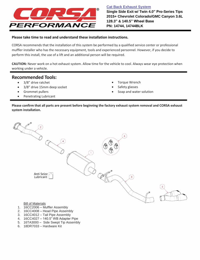
Please confirm that all parts are present before beginning the factory exhaust system removal and CORSA exhaust system installation.
Bill of Materials 1. 16CC2006 – Muffler Assembly2. 16CC4008 – Head Pipe Assembly3. 16CC4012 – Tail Pipe Assembly4. 16CC4027 – 140.5” WB Adapter Pipe5. 16TA3000 – Side Swept Tip Assembly6. 18DR7033 – Hardware Kit
Cat Back Exhaust System
Single Side Exit w/ Twin 4.0” Pro-Series Tips
2015+ Chevrolet Colorado/GMC Canyon 3.6L
128.3” & 140.5” Wheel Base
PN: 14744, 14744BLK
Factory Exhaust System Removal:
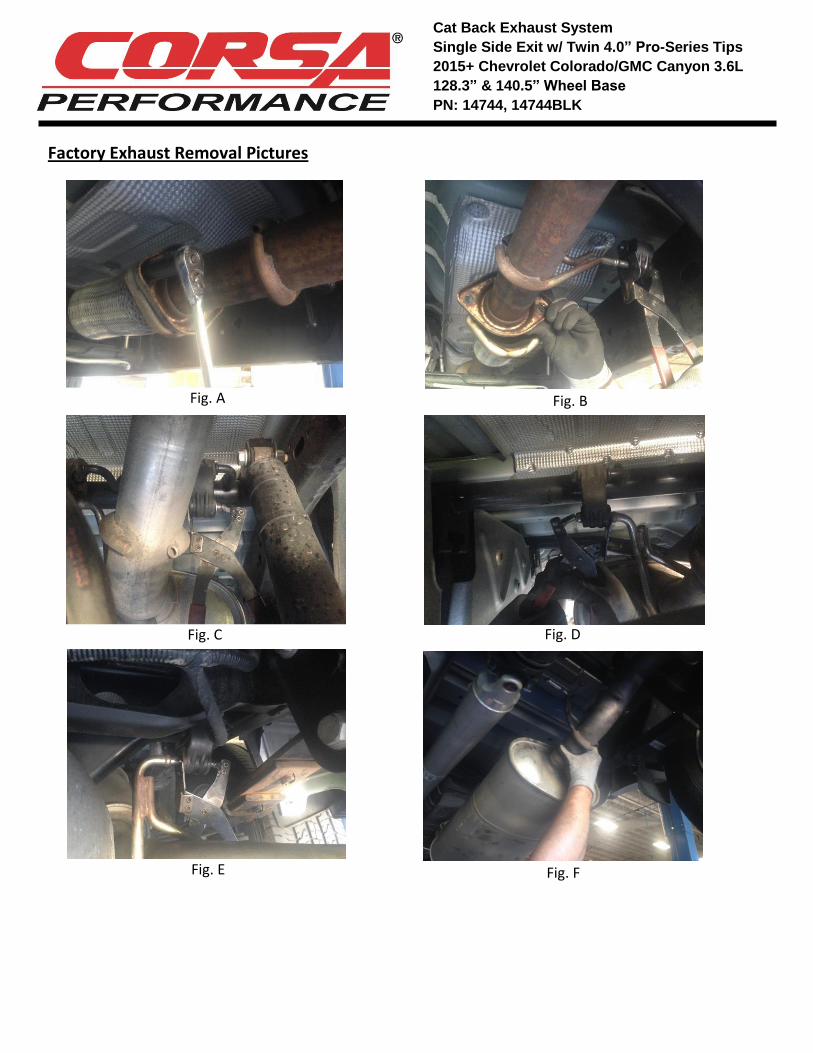
1. Beginning near the factory flex section, remove the two retaining nuts at the flange connection using the ratchetand 15mm deep socket. Place the nuts in a safe location, as they will be reused during the installation of theCorsa exhaust system. (Fig A)
Note: Penetrating lubricant may make this step easier.
2. Downstream of the flange connection, remove the hanger from the rubber grommet using grommet pullers or asimilar device. (Fig B)
Note: A soap and water solution may aid in the removal of hangers.
3. Support the front portion of the exhaust system (just in front of the muffler) using a jack stand or similar device.
4. Remove the two hangers from the rubber grommets downstream of the muffler using grommet pullers or asimilar device. (Fig C & D)
Note: At this point, the exhaust is only supported by the jack stand and the hanger near the tip. Take care to notlet the exhaust system tip or roll as it may damage the vehicle and/or cause personal injury.
5. Using the grommet pullers, remove the last hanger near the tip. (Fig E)
6. Carefully remove the factory exhaust system from the vehicle by pulling the exhaust system forward through thechassis, rotating it as needed to clear the suspension and spare tire heat shield. (Fig F)
Note: Take care to not damage the brake lines or wires near the rear axle when moving the exhaust system.
7. This concludes the factory exhaust system removal process.
Cat Back Exhaust System
Single Side Exit w/ Twin 4.0” Pro-Series Tips
2015+ Chevrolet Colorado/GMC Canyon 3.6L
128.3” & 140.5” Wheel Base
PN: 14744, 14744BLK
Factory Exhaust Removal Pictures
Fig. A Fig. B
Fig. C Fig. D
Fig. E Fig. F
Cat Back Exhaust System
Single Side Exit w/ Twin 4.0” Pro-Series Tips
2015+ Chevrolet Colorado/GMC Canyon 3.6L
128.3” & 140.5” Wheel Base
PN: 14744, 14744BLK
Installation of CORSA Exhaust System:
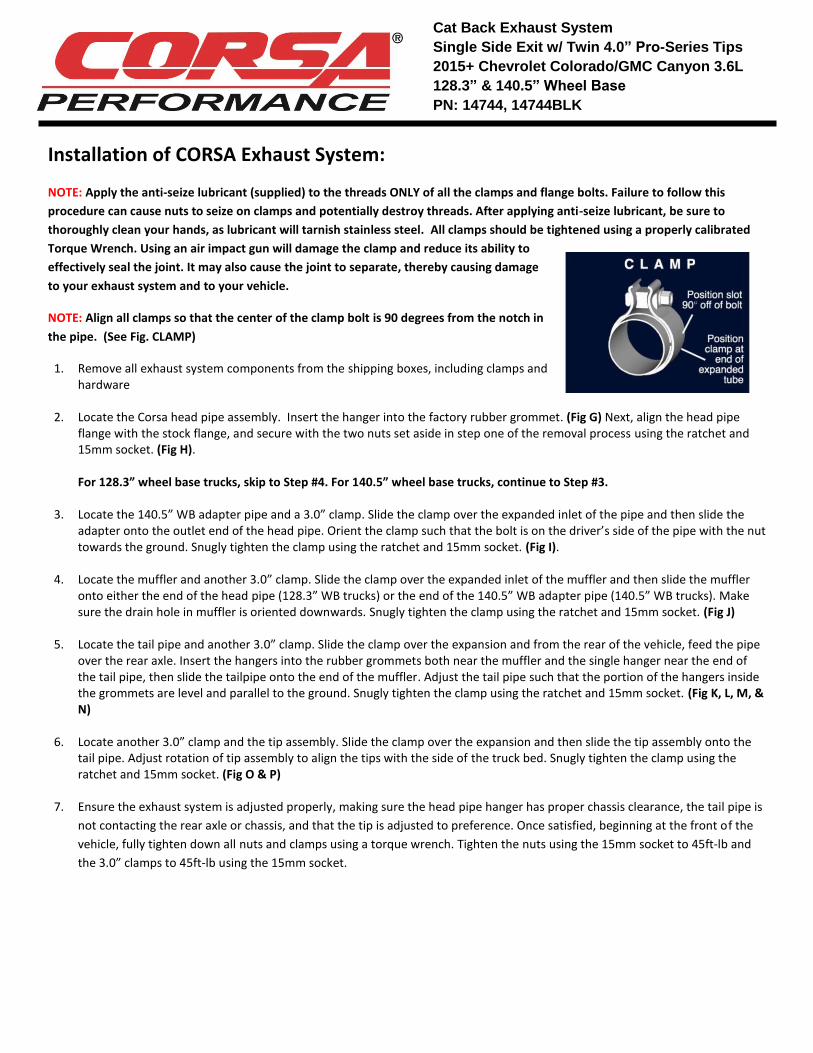
NOTE: Apply the anti-seize lubricant (supplied) to the threads ONLY of all the clamps and flange bolts. Failure to follow this
procedure can cause nuts to seize on clamps and potentially destroy threads. After applying anti-seize lubricant, be sure to
thoroughly clean your hands, as lubricant will tarnish stainless steel. All clamps should be tightened using a properly calibrated
Torque Wrench. Using an air impact gun will damage the clamp and reduce its ability to
effectively seal the joint. It may also cause the joint to separate, thereby causing damage
to your exhaust system and to your vehicle.
NOTE: Align all clamps so that the center of the clamp bolt is 90 degrees from the notch in
the pipe. (See Fig. CLAMP)
1. Remove all exhaust system components from the shipping boxes, including clamps andhardware
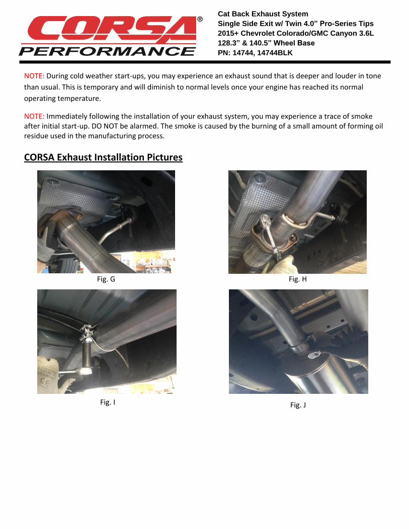
2. Locate the Corsa head pipe assembly. Insert the hanger into the factory rubber grommet. (Fig G) Next, align the head pipeflange with the stock flange, and secure with the two nuts set aside in step one of the removal process using the ratchet and15mm socket. (Fig H).
For 128.3” wheel base trucks, skip to Step #4. For 140.5” wheel base trucks, continue to Step #3.
3. Locate the 140.5” WB adapter pipe and a 3.0” clamp. Slide the clamp over the expanded inlet of the pipe and then slide theadapter onto the outlet end of the head pipe. Orient the clamp such that the bolt is on the driver’s side of the pipe with the nuttowards the ground. Snugly tighten the clamp using the ratchet and 15mm socket. (Fig I).
4. Locate the muffler and another 3.0” clamp. Slide the clamp over the expanded inlet of the muffler and then slide the muffleronto either the end of the head pipe (128.3” WB trucks) or the end of the 140.5” WB adapter pipe (140.5” WB trucks). Makesure the drain hole in muffler is oriented downwards. Snugly tighten the clamp using the ratchet and 15mm socket. (Fig J)
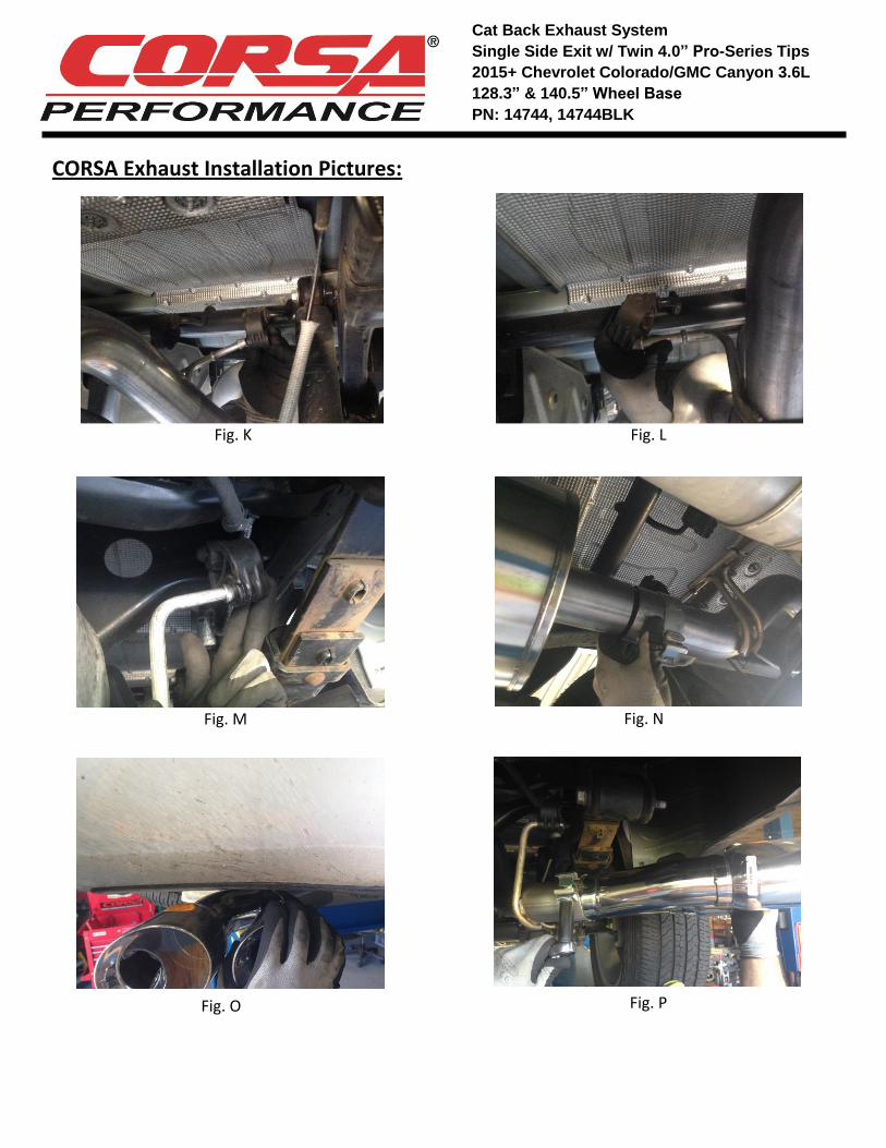
5. Locate the tail pipe and another 3.0” clamp. Slide the clamp over the expansion and from the rear of the vehicle, feed the pipeover the rear axle. Insert the hangers into the rubber grommets both near the muffler and the single hanger near the end ofthe tail pipe, then slide the tailpipe onto the end of the muffler. Adjust the tail pipe such that the portion of the hangers insidethe grommets are level and parallel to the ground. Snugly tighten the clamp using the ratchet and 15mm socket. (Fig K, L, M, &N)
6. Locate another 3.0” clamp and the tip assembly. Slide the clamp over the expansion and then slide the tip assembly onto thetail pipe. Adjust rotation of tip assembly to align the tips with the side of the truck bed. Snugly tighten the clamp using theratchet and 15mm socket. (Fig O & P)
7. Ensure the exhaust system is adjusted properly, making sure the head pipe hanger has proper chassis clearance, the tail pipe is
not contacting the rear axle or chassis, and that the tip is adjusted to preference. Once satisfied, beginning at the front of the
vehicle, fully tighten down all nuts and clamps using a torque wrench. Tighten the nuts using the 15mm socket to 45ft-lb and
the 3.0” clamps to 45ft-lb using the 15mm socket.
Cat Back Exhaust System
Single Side Exit w/ Twin 4.0” Pro-Series Tips
2015+ Chevrolet Colorado/GMC Canyon 3.6L
128.3” & 140.5” Wheel Base
PN: 14744, 14744BLK
NOTE: During cold weather start-ups, you may experience an exhaust sound that is deeper and louder in tone
than usual. This is temporary and will diminish to normal levels once your engine has reached its normal
operating temperature.
NOTE: Immediately following the installation of your exhaust system, you may experience a trace of smoke after initial start-up. DO NOT be alarmed. The smoke is caused by the burning of a small amount of forming oil residue used in the manufacturing process.
CORSA Exhaust Installation Pictures
Fig. G Fig. H
Fig. I Fig. J
Cat Back Exhaust System
Single Side Exit w/ Twin 4.0” Pro-Series Tips
2015+ Chevrolet Colorado/GMC Canyon 3.6L
128.3” & 140.5” Wheel Base
PN: 14744, 14744BLK
CORSA Exhaust Installation Pictures:
Fig. K Fig. L
Fig. M Fig. N
Fig. O Fig. P