corrosion in the refining industry nace fcw, · pdf filenace corrosion in the oil refining...
TRANSCRIPT

NACE Corrosion in the Oil Refining Industry
Corrosion in the Refining Industry
NACE FCW, 1996
Corrosion and Other Failures
Lynne Kaley
DNV (USA) Inc. - Houston, Texas

NACE Corrosion in the Oil Refining Industry
Purpose
• Brief overview of the types of corrosion and other deterioration mechanisms active in typical refinery processes
• Discussion of corrosion and other types of damage occuring at high and low temperature conditions
• Description of low and high temperature corrosion principles and the process conditions that drive them

NACE Corrosion in the Oil Refining Industry
Low Temperature Corrosion
• Below 500OF (260OC)
• Presence of water (even in very small amounts)
• Electrolyte in hydrocarbon stream
• Obeys electrochemical laws
• Stable films can reduce or prevent corrosion
• Vapor streams - at water condensation points

NACE Corrosion in the Oil Refining Industry
High Temperature Corrosion
• Above 500OF (260OC)
• No water present
• Result of a reaction between metal and process ions (such as oxygen, sulfur, etc.)

NACE Corrosion in the Oil Refining Industry
Causes of Deterioration
• Normal operation, upset, startup/shutdown conditions
• Refineries contain over (15) different process units
• Material/Environment condition interactions
• Many combinations of corrosive process streams and temperature/pressure conditions
• In the absence of corrosion, mechanical and metallurgical deterioration can occur
NACE Corrosion in the Oil Refining Industry
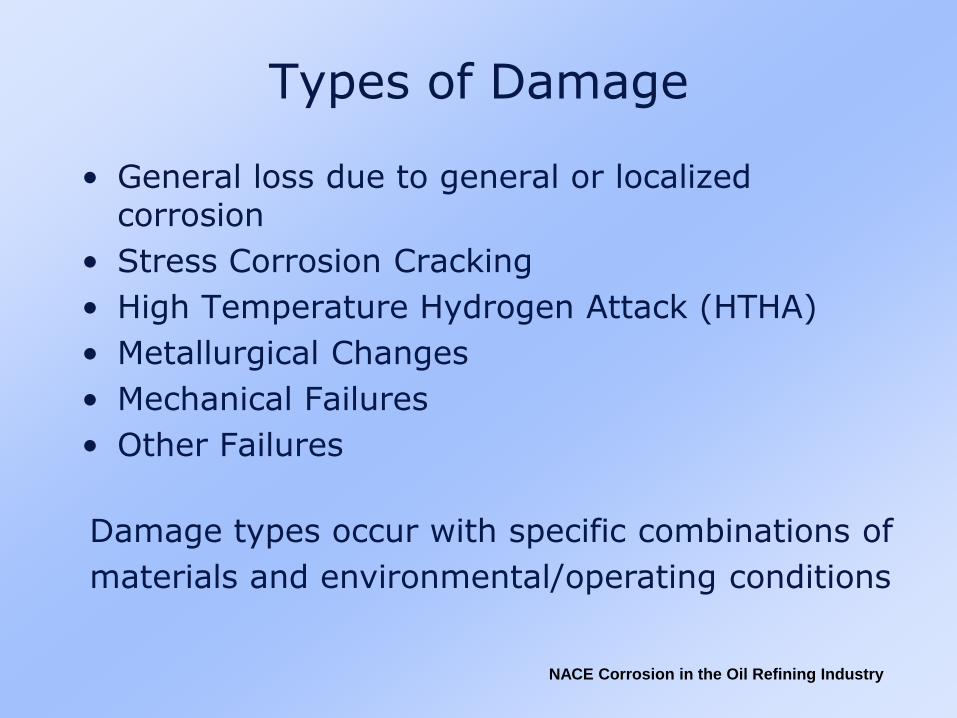
Types of Damage
• General loss due to general or localized corrosion
• Stress Corrosion Cracking
• High Temperature Hydrogen Attack (HTHA)
• Metallurgical Changes
• Mechanical Failures
• Other Failures
Damage types occur with specific combinations of
materials and environmental/operating conditions

NACE Corrosion in the Oil Refining Industry
Corrosion Principles
• Corrosion rate is measured as weight loss per unit area and is expressed in mils per year (mpy)
• Rates can be affected by:
– Passivity forming protective surface films (including corrosion inhibitors, paints and coatings)
– Oxygen content
– Flow velocity/rates
– Temperature
– Acidic conditions

NACE Corrosion in the Oil Refining Industry
Process Corrosion Low Temperature Conditions
• Not caused by hydrocarbons
• Caused by inorganic compounds such as water, hydrogen sulfide, hydrogen chloride, sulfuric acid, etc.
• Crude oil contaminants
• Process chemicals

NACE Corrosion in the Oil Refining Industry
Process CorrosionHigh Temperature Conditions
• Important due to serious consequences
• High temperatures usually involve high pressures
• Dependent on the nature of the scale formed
– general thinning
– localized thinning (pitting)
– intergranular attack
– mixed phase flow
• Corrosion due to sulfur compounds most common and well documented

NACE Corrosion in the Oil Refining Industry
Corrosives Found in Refining Processes
Sulfur Present in raw crude. It causes high-temperature
sulfidation of metals, and it combines with other
elements to form aggressive compounds, such as
various sulfides and sulfates, sulfurous, polythionic,
and sulfuric acids.
Naphthenic Acid A collective name for organic acids found primarily
in crude oils from western United States, certain
Texas and Gulf Coast and a few Mid-East oils.
Polythionic Acid Sulfurous acids formed by the interaction of sulfides,
moisture, and oxygen, an occurring when equipment
is shutdown.
Chlorides Present in the form of salts (such as magnesium
chloride and calcium chloride) originating from
crude oil, catalysts, and cooling water.

NACE Corrosion in the Oil Refining Industry
Corrosives Found in Refining Processes
Carbon Dioxide Occurs in steam reforming of hydrocarbon in
hydrogen plants, and to some extent in catalytic
cracking. CO2 combines with moisture to form
carbonic acid.
Ammonia Nitrogen in feedstocks combines with hydrogen to
form ammonia - or ammonia is used for
neutralization - which in turn may combine with
other elements to form corrosive compounds, such as
ammonium chloride.
Cyanides Usually generated in the cracking of high-nitrogen
feedstocks. When present, corrosion rates are likely
to increase.

NACE Corrosion in the Oil Refining Industry
Corrosives Found in Refining Processes
Hydrogen Chloride Formed through hydrolysis of magnesium chloride
and calcium chloride, it is found in many overhead
(vapor) streams. On condensation, it forms highly
aggressive hydrochloric acid.
Sulfuric Acid Used as a catalyst in alkylation plants and is formed
in some process steams containing sulfur trioxide,
water and oxygen.
Hydrogen In itself not corrosive but can lead to blistering and
embrittlement of steel. Also, it readily combines
with other elements to produce corrosive
compounds.

NACE Corrosion in the Oil Refining Industry
Corrosives Found in Refining Processes
Phenols Found primarily in sour water strippers.
Oxygen Originates in crude, aerated water, or packing gland
leaks. Oxygen in the air used with fuel in furnace
combustion and FCC regeneration results in high-
temperature environments which cause oxidation and
scaling of metal surfaces of under-alloyed materials.
Carbon Not corrosive but at high temperature results in
carburization that causes embrittlement or reduced
corrosion resistance in some alloys.

NACE Corrosion in the Oil Refining Industry
Metal LossGeneral and/or Localized
• Galvanic corrosion
• Pitting
• Crevice corrosion
• Intergranular attack
• Erosion corrosion
• Hydrogen chloride
• Ammonia bisulfide
• Carbon dioxide
• Process chemicals
• Organic chlorides
• Aluminum chloride
• Sulfuric acid
• Hydrofluoric acid
• Phosphoric acid
• Phenol (carbolic acid)
• Amine
• Atmospheric corrosion
• Corrosion under insulation
• Oxidation
• High temperature sulfidation
• Naphthenic acid

NACE Corrosion in the Oil Refining Industry
Galvanic Corrosion
Corroded End - Anodic - More ActiveMagnesiumMagnesium alloysZincAluminumAluminum alloysSteelCast ironType 410 stainless steel (active state)Ni-ResistType 304 stainless steel (active state)Type 316 stainless steel (active state)LeadTinNickel (active state)
BrassCopperBronzeCopper-NickelMonelNickel (passive state)Type 410 stainless steel (passive state)Type 304 stainless steel (passive state)Type 316 stainless steel (passive state)TitaniumGraphiteGoldPlatinumProtected End - Cathodic - Less Active

NACE Corrosion in the Oil Refining Industry
Oxidation
Alloy Temperature, OFCarbon Steel
Carbon - 1/2 Mo
1 1/4 Cr-1/2 Mo
2 1/4 Cr-1Mo
5 Cr-1/2 Mo
7 Cr-1/2 Mo
9 Cr-1Mo
Type 410 stainless steel
Types 304, 321, and 347 stainless steel
1,050
1,050
1,100
1,175
1,200
1,250
1,300
1,500
1,600

NACE Corrosion in the Oil Refining Industry
Oxidation (continued)
Alloy Temperature (oF)
Types 316 and 317 stainless steel
Type 309 stainless steel
Type 310 stainless steel
Monel 400
Inconel 625
Incoloy 825
Hastelloy B-2
Hastelloy C-4 and C-276
1,600
2,000
2,100
1,000
2,000
2,000
1,400
1,800

NACE Corrosion in the Oil Refining Industry
Sulfuric Acid
NACE Corrosion in the Oil Refining Industry
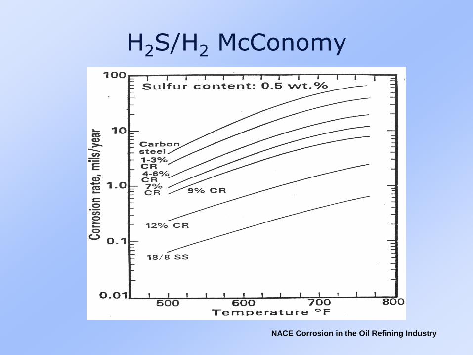
H2S/H2 McConomy
NACE Corrosion in the Oil Refining Industry
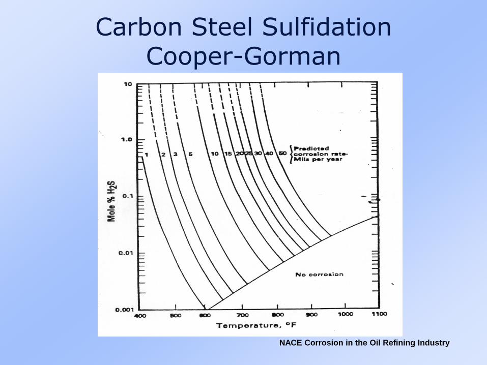
Carbon Steel SulfidationCooper-Gorman

NACE Corrosion in the Oil Refining Industry
H2S/H2 Material Corrosion

NACE Corrosion in the Oil Refining Industry
Stress Corrosion Cracking
• Chloride stress corrosion cracking
• Caustic stress cracking
• Polythionic acid stress corrosion cracking
• Ammonia stress corrosion cracking
• Hydrogen effects (in steels)
• Sulfide stress corrosion cracking, hydrogen induced cracking, stress oriented hydrogen induced cracking
• Hydrogen cyanide

NACE Corrosion in the Oil Refining Industry
Stress Corrosion Cracking
Alloy Environment
Aluminum Base
Magnesium Base
Copper Base
AirSea WaterSalt and chemical combinations
Nitric acidCausticHF solutionsSaltsCoastal atmospheres
Primarily ammonia and ammonium hydroxideAminesMercury

NACE Corrosion in the Oil Refining Industry
Carbon Steel
Martensitic and PrecipitationHardening Stainless Steels
Austenitic Stainless Steels
CausticAnhydrous ammoniaNitrate solutions
Sea waterChloridesH2S solutions
Chlorides - inorganic and organicCaustic solutionsSulfurous and polythionic acids
Alloy Environment
Stress Corrosion Cracking

NACE Corrosion in the Oil Refining Industry
Nickel Base
Titanium
Caustic above 600OF (315OC)Fused causticHydrofluoric acid
Sea waterSalt atmospheresFused salt
(Simplified: See Logan, H.L, “The Stress Corrosion of Metals”.
John Wiley & Sons, for Comprehensive List.
Stress Corrosion Cracking
Alloy Environment

NACE Corrosion in the Oil Refining Industry
Wet H2S Cracking
• Hydrogen from corrosion reaction
• Fe + H2S => FeS + 2H
• 2H => H2
• Leads to various types of damage in steels
– Blistering
– Sulfide Stress Corrosion Cracking(SSC)
– Hydrogen Induced Cracking (HIC)
– Stress Oriented Hydrogen Induced Cracking (SOHIC)

NACE Corrosion in the Oil Refining Industry
Wet H2S Cracking
SOHIC in soft base metal extending from the
tip of SSC in a hard HAZ of a repair weld in
the shell of a primary absorber (de-ethanizer)
column in a FCC gas plant. The A 212-B
steel shell was PWHT’d at original
fabrication, but the repair weld was not.
(Nital etch)

NACE Corrosion in the Oil Refining Industry
This micrograph shows the cross-sectional view of a representative crack. The depth is
approximately 0.021”. The blistering effect can be seen as the metal above the crack
appears to have been bulged out toward the surface.
Magnification: 30x Etch: 3% Nital

NACE Corrosion in the Oil Refining Industry
This is micrograph of the crack tip observed in the previous figure. Note that crack
propagation took place at the grain boundaries, characteristic of hydrogen induced
cracking.
Magnification: 150x Etch: 3% Nital

NACE Corrosion in the Oil Refining Industry

NACE Corrosion in the Oil Refining Industry

NACE Corrosion in the Oil Refining Industry
Hydrogen Induced Cracking

NACE Corrosion in the Oil Refining Industry
Micrograph of boat sample (longitudinal cut) taken from HSC 3055
Magnification: 50x Etch: 3% Nital

NACE Corrosion in the Oil Refining Industry
Photo of Wet Fluorescent Magnetic Particle indications. Note the number of
indications spread throughout the surface. This indicates the phenomena is not
localized to a single area. The light blue areas are paint marks used for identification,
and the dark blue areas are paint marks found on the as received plate.

NACE Corrosion in the Oil Refining Industry
Photo of Wet Fluorescent Magnetic Particle surface indications found. The crescent
shape indicates hydrogen blistering as the possible damage mechanism. The bluish
circle around the indication is just a paint marking used to help identify crack sites.
This indication is approximately 3/32” in length.

NACE Corrosion in the Oil Refining Industry
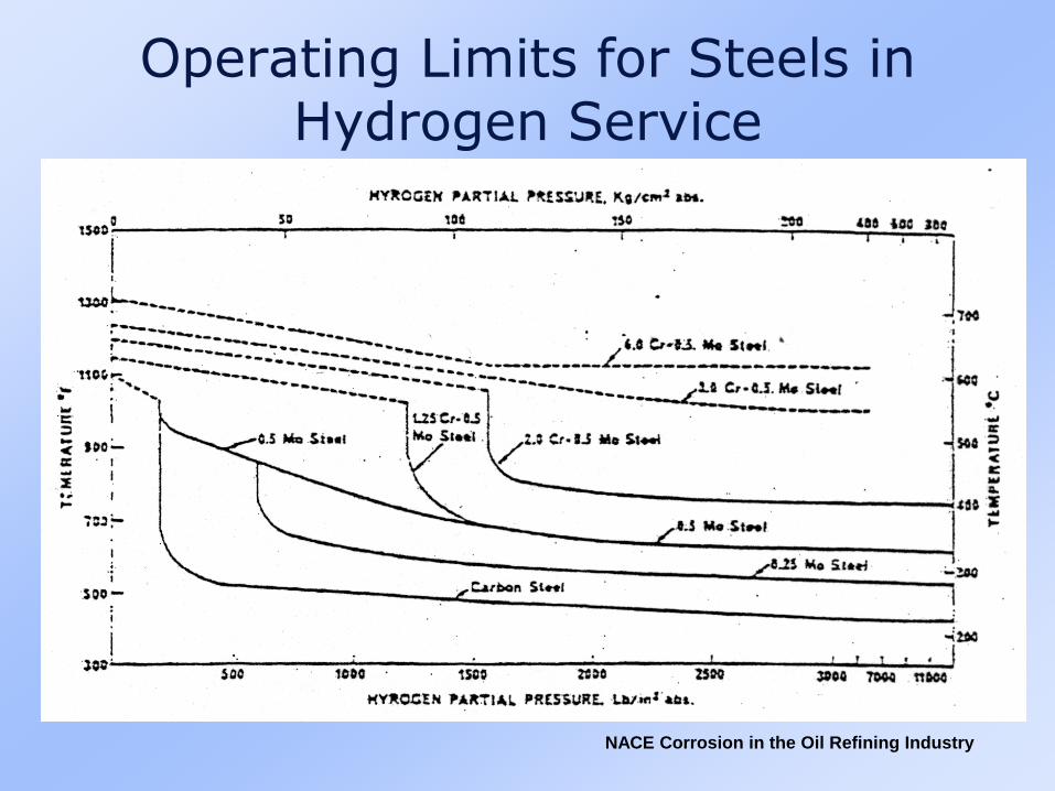
High Temperature Hydrogen Attack (HTHA)
• Carbon and low alloys steels exposed to hydrogen above 430OF (221OC)
• Partial pressure above 200 psi (1378 kPa)
• Dissociation of molecular hydrogen to atomic hydrogen
• Atomic hydrogen permeation into the steel
• Reaction of atomic hydrogen with carbon in steel
• Formation of methane at discontinuities
• API 941 recommended for new installation
NACE Corrosion in the Oil Refining Industry
Operating Limits for Steels in Hydrogen Service

NACE Corrosion in the Oil Refining Industry
WELD HAZ BASE
Magnification: 50x Etch: 2% Nital
Longitudinal Weld

NACE Corrosion in the Oil Refining Industry
Longitudinal Weld
Magnification: 500x Etch: 2% Nital
NACE Corrosion in the Oil Refining Industry
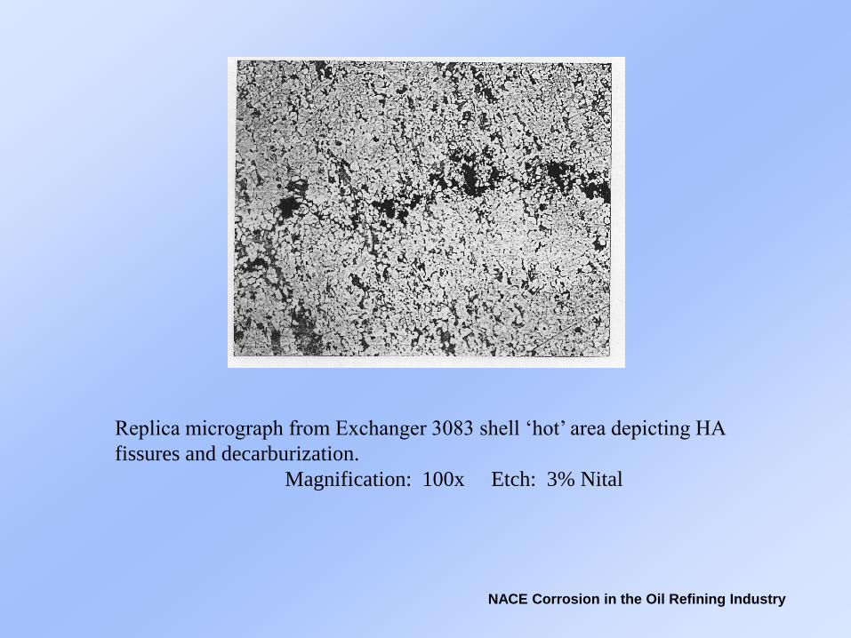
Replica micrograph from Exchanger 3083 shell ‘hot’ area depicting HA
fissures and decarburization.
Magnification: 100x Etch: 3% Nital

NACE Corrosion in the Oil Refining Industry
Enlarged micrograph of previous figure. Notice decarburization.
Magnification: 500x Etch: 3% Nital

NACE Corrosion in the Oil Refining Industry
Metallurgical and Environmental Failures
• Grain growth
• Graphitization
• Hardening
• Sensitization
• Sigma phase
• 885OF Embrittlement
• Temper embrittlement
• Liquid metal embrittlement
• Carburization
• Metal dusting
• Decarburization
• Selective leaching

NACE Corrosion in the Oil Refining Industry
Mechanical Failures
• Incorrect or defective materials
• Mechanical fatigue
• Corrosion fatigue
• Cavitation damage
• Mechanical damage
• Overloading
• Over pressurization
• Brittle fracture
• Creep
• Stress rupture
• Thermal shock
• Thermal fatigue

NACE Corrosion in the Oil Refining Industry
Conclusions
• There are many causes of equipment failures in the refining industry
• Many are common and well documented
• Other, less common deterioration mechanisms are not well documented
• Deterioration is the results of metal and environment/operating conditions combinations
• These combinations vary somewhat in different process units
• Focus of the Corrosion in the Oil Refining Industry Conference