correlation between corrosion of reinforcing steel and...
TRANSCRIPT
TRANSPORT A T!ON RESEARCH RECORD 1211
Correlation Between Corrosion of Reinforcing Steel and Voids and Cracks in Concrete Structures
B. BoRGARD, C. WARREN, S. SoMAYAJI, AND R. HEIDERSBACH
The corrosion of metals in concrete is a multibillion-dollar problem in the United States. Most of the corrosion-in-concrete literature claims that deicing salts, or other sources of environmental chlorides, permeate concrete structures and lead to corrosion, which causes subsequent cracking of the overlying concrete. This report presents the results of analyses of corroded reinforced concrete structures and correlates structural loading patterns, cracking, and corrosion. The results of these analyses support the conclusion that, for the structures analyzed, the corrosion was a consequence of cracking.
The corrosion of metals in concrete and similar cementitious materials has been a matter of concern for decades. Some of the earliest National Bureau of Standards (NBS) reports discussed corrosion in concrete (1,2), and a 1940s NBS report dealt with corrosion in masonry buildings (3).
Industrial practice through the 1960s was to assume that "quality concrete" would limit or prevent corrosion. Emphasis was placed on following quality control procedures, maintaining adequate depth of cover (2.5 cm or more, depending on the authority in question) ( 4), and using concrete with low water :cement ratios and high cement factors (5).
Although there were isolated failures of metals in concrete (5-8), and some limited research reports (9), interest in this subject was at a low level until problems associated with the United States interstate highway program began to attract attention in the early 1970s (10). Since that time virtually all concrete-related corrosion research in the United States has been directed at highway bridges and structures. The focus of this effort is justified by the magnitude of the highway problem, which has been estimated to require billions of dollars in the United States (11,12).
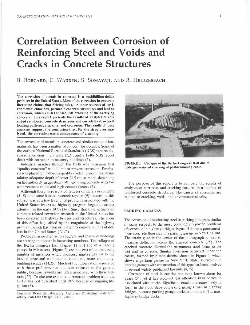
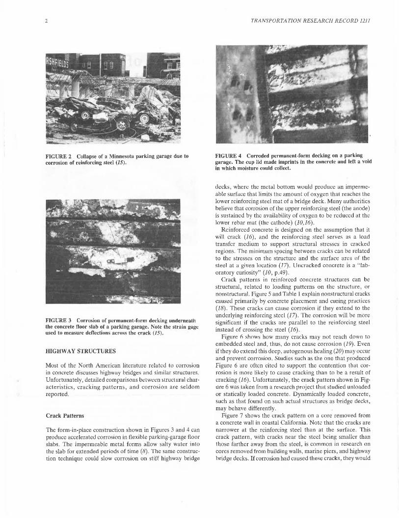
Problems associated with concrete and masonry buildings are starting to appear in increasing numbers. The collapse of the Berlin Congress Hall (Figure 1) (13) and of a parking garage in Minnesota (Figure 2) are but two of an increasing number of instances where moisture ingress has led to the loss of structural components, roofs, or, more commonly, building facades (14,15). Much of the information associated with these problems has not been released to the general public, because lawsuits are often associated with these fa ilures (15). To cite one example, a reported problem from the 1960s was not published until 1977 because of ongoing litigation (8).
Corrosion Research Laboratory , California Polytechnic State University, San Luis Obispo, Calif. 93407.
--~
FIGURE 1 Collapse of the Berlin Congress Hall due to hydrogen-assisted cracking of post-tensioning cable.
The purpose of this report is to compare the results of analyses of corrosion and cracking patterns in a number of reinforced concrete structures. The causes of corrosion are related to cracking, voids , and environmental salts .
PARKING GARAGES
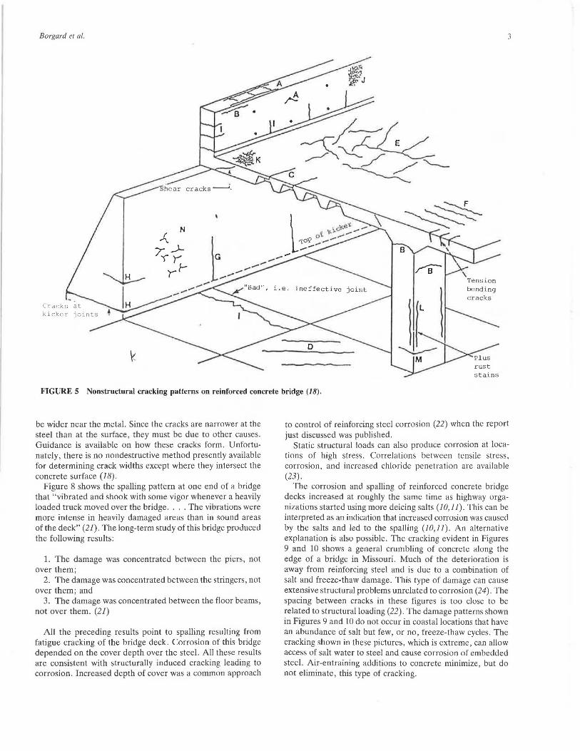
The corrosion of reinforcing steel in parking garages is similar in many respects to the more commonly reported problems of corrosion in highway bridges. Figure 3 shows a permanentform concrete floor slab in a parking garage in.New England. The strain gage in the center of the photograph is used to measure deflection across the cracked concrete (15). The cracked concrete allowed the permanent steel forms to get wet and to corrode. Similar corrosion occurred under the cavity , formed by plastic debris, shown in Figure 4, which shows a parking garage in New York State. Corrosion in parking garages with construction of this type has been involved in several widely publicized lawsuits (8,15).
Corrosion of steel in cavities has been known about for years (5), yet it has received less attention than corrosion associated with cracks. Significant cracks are more likely to form in the floor slabs of parking garages than in highway bridges , because parking garage decks are not as stiff as most highway bridge decks.
2
FIGURE 2 Collapse of a Minnesota parking garage due to corrosion of reinforcing steel (15).
FIGURE 3 Corrosion of permanent-form decking underneath the concrete floor slab of a parking garage. Note the strain gage used to measure deflections across the crack (15).
HIGHWAY STRUCTURES
Most of the North American literature related to corrosion in concrete discusses highway bridges and similar structures. Unfortunately, detailed comparisons between structural characteristics , cracking patterns, and corrosion are seldom reported.
Crack Patterns
The form-in-place construction shown in Figures 3 and 4 can produce accelerated corrosion in flexible parking-garage floor slabs. The impermeable metal forms allow salty water into the slab for extended periods of time (8) . The same construction technique could slow corrosion on stiff highway bridge
TRANSPORTATION RESEARCH RECORD 1211
FIGURE 4 Corroded permanent-form decking on a parking garage. The cup lid made imprints in the concrete and left a void in which moisture could collect.
decks , where the metal bottom would produce an impermeable surface that limits the amount of oxygen that reaches the lower reinforcing steel mat of a bridge deck. Many authorities believe that corrosion of the upper reinforcing steel (the anode) is sustained by the availability of oxygen to be reduced at the lower rebar mat (the cathode) (10,16).
Reinforced concrete is designed on the assumption that it will crack (16), and the reinforcing steel serves as a load transfer medium to support structural stresses in cracked regions. The minimum spacing between cracks can be related to the stresses on the structure and the surface area of the steel at a given location (17). Uncracked concrete is a "laboratory curiosity" (10, p.49) .
Crack patterns in reinforced concrete structures can be structural, related to loading patterns on the structure, or nonstructural. Figure 5 and Table 1 explain nonstructural cracks causeu primarily by concrete placement and curing practices (J 8). These cracks can cause corrosion if they extend to the underlying reinforcing steel (17). The corrosion will be more significant if the cracks are parallel to the reinforcing steel instead of crossing the steel (16) .
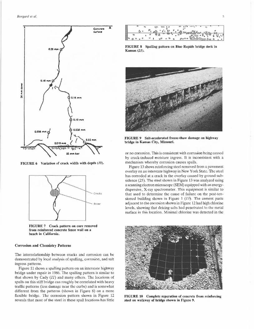
Figure 6 shows how many cracks may not reach down to embedded steel and, thus, do not cause corrosion (19). Even if they do extend this deep, autogenous healing (20) may occur and prevent corrosion. Studies such as the one that produced Figure 6 are often cited to support the contention that corrosion is more likely to cause cracking than to be a result of cracking (16). Unfortunately , the crack pattern shown in Figure 6 was taken from a research project that studied unloaded or statically loaded concrete. Dynamically loaded concrete, such as that found on such actual structures as bridge decks, may behave differently.
Figure 7 shows the crack pattern on a core removed from a concrete wall in coastal California. Note that the cracks are narrower at the reinforcing steel than at the surface. This crack pattern, with cracks near the steel being smaller than those farther away from the steel, is common in research on cores removed from building walls, marine piers, and highway bridge decks. If corrosion had caused these cracks, they would
Borgard et al.
FIGURE 5 Nonstructural cracking patterns on reinforced concrete bridge (18).
be wider near the metal. Since the cracks are narrower at the steel than at the surface, they must be due to other causes. Guidance is available on how these cracks form. Unfortunately, there is no nondestructive method presently available for determining crack widths except where they intersect the concrete surface (18).
Figure 8 shows the spalling pattern at one end of a bridge that "vibrated and shook with some vigor whenever a heavily loaded truck moved over the bridge .... The vibrations were more intense in heavily damaged areas than in sound areas of the deck" (21). The long-term study of this bridge produced the following results:
1. The damage was concentrated between the piers, not over them;
2. The damage was concentrated between the stringers, not over them; and
3. The damage was concentrated between the floor beams, not over them. (21)
All the preceding results point to spalling resulting from fatigue cracking of the bridge deck. Corrosion of this bridge depended on the cover depth over the steel. All these results are consistent with structurally induced cracking leading to corrosion. Increased depth of cover was a common approach
to control of reinforcing steel corrosion (22) when the report just discussed was published.
Static structural loads can also produce corrosion at locations of high stress. Correlations between tensile stress, corrosion, and increased chloride penetration are available (23).
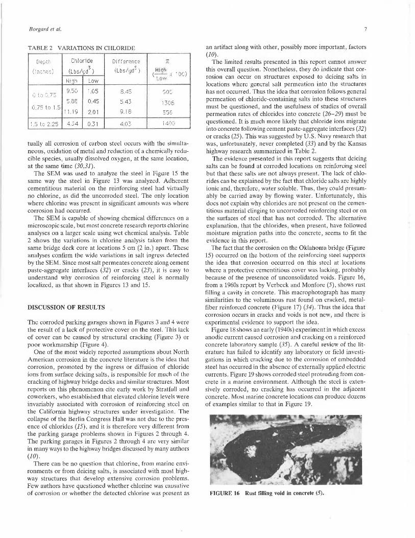
The corrosion and spalling of reinforced concrete bridge decks increased at roughly the same time as highway organizations started using more deicing salts (10,11). This can be interpreted as an indication that increased corrosion was caused by the salts and led to the spalling (10,11). An alternative explanation is also possible. The cracking evident in Figures 9 and 10 shows a general crumbling of concrete along the edge of a bridge in Missouri. Much of the deterioration is away from reinforcing steel and is due to a combination of salt and freeze-thaw damage. This type of damage can cause extensive structural problems unrelated to corrosion (24). The spacing between cracks in these figures is too close to be related to structural loading (22). The damage patterns shown in Figures 9 and 10 do not occur in coastal locations that have an abundance of salt but few, or no, freeze-thaw cycles. The cracking shown in these pictures, which is extreme, can allow access of salt water to steel and cause corrosion of embedded steel. Air-entraining additions to concrete minimize, but do not eliminate, this type of cracking.
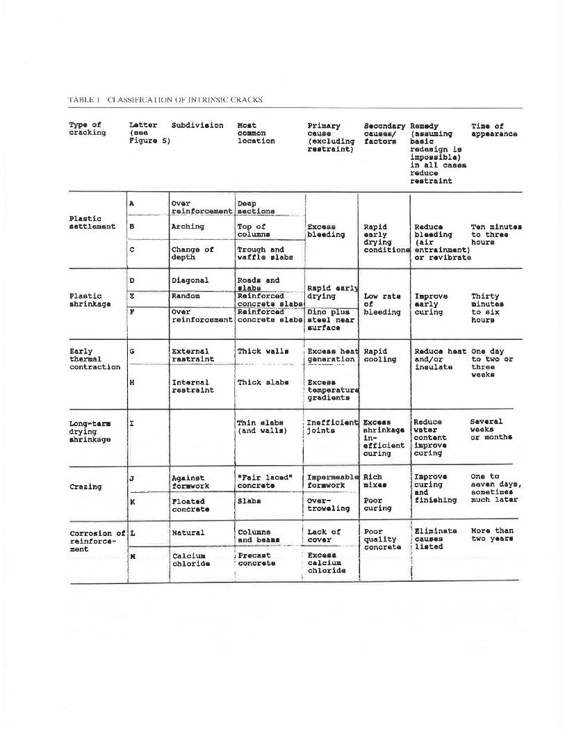
TABLE 1 CLASSIFICATION OF INTRINSIC CRACKS
Type of cracking
Plastic settlement
Plastic shrinka9e
Early thermal contraction
Long-term drying shrinka9e
Letter Subdivision (aee
Moat co111111on location
Primary cauae (excluding restraint)
Figure 5)
A
B Arching Top of Exce&a
over Deep I reinfq!:c~.!!:l~ ..!_!ctions _ _ ~
i-----+--------+-c-~lumna bleeding
c Change of Trough and depth waffle alaba I
D Dia9onal Road• and r=-----;----,,------+-•~l=a~b~s~-·~--~ Rapid earll E Random Reinforced drying
F
G
concrete slabs over Reinforced ... _ _,._D.,......in_o_p~1l_u_s__,
reinforcement concrete slabs ateel near surface
External restraint
Thick walla I , Exceaa heat
- - ---t-------""i"- - . ·-- ·j ~-!~~a~~on H
I
Internal restraint
Thick alaba
Thin elaba (and walls)
Exceaa I tamperatur1 / qradianta
I j inefficient I joints
I
Secondary cauaea/ factor•
Rapid early dryin9 condition•
Low rate of bleeding
Rapid cooling
Excaaa shrinkage inefficient curing
J Againat formwork
"Fair laced" concrete
Imperineable Rich Crazing
K
Corrosion of L reinforcement
j" I
Floated concrete
Natural
Calcium chloride
Slaba
Columns and beama
1 Precaat i concrete
!
formwork mixes
I over-, troweling
i Lack of 1 cover ----·~·-~-
Exceaa calcium chloride
Poor curing
Poor quality concrete
Remedy (uauming bade redesign ia impoasible) in all casea reduce restraint
Time of appearance
Reduce Ten minutea
J
bleedin9 to three (air hours entrainment) or revibrato
Improve early curing
Reduce heat and/or insulate
Reduce water content improve curing
Improve curing and finiahin9
Thirty minutes to six hours
One day to two or three weeka
Several weeks or months
one to seven days, sometimes much later
. Eliminate J causes listed
More than two yeara
Borgard et al.
0.28"""
Concrtlt 1ur11c1
FIGURE 6 Variation of crack width with depth (19).
Cnicks
Rebor
FIGURE 7 Crack pattern on core removed from reinforced concrete fence wall on a beach in California.
Corrosion and Chemistry Patterns
The interrelationship between cracks and corrosion can be demonstrated by local analysis of spalling, corrosion, and salt ingress patterns.
Figure 11 shows a spalling pattern on an interstate highway bridge under repair in 1986. The spalling pattern is similar to that shown by Cady (11) and many others . The locations of spalls on this stiff bridge can roughly be correlated with heavy traffic patterns (less damage near the curbs) and is somewhat different from the patterns (shown in Figure 8) on a more flexible bridge. The corrosion pattern shown in Figure 12 reveals that most of the steel in these spall locations has little
Cit 0 0 0 "'' 8
FIGURE 8 Spalling pattern on Blue Rapids bridge deck in Kansas (21).
FIGURE 9 Salt-accelerated freeze-thaw damage on highway bridge in Kansas City, Missouri.
5
or no corrosion. This is consistent with corrosion being caused by crack-induced moisture ingress. It is inconsistent with a mechanism whereby corrosion causes spalls.
Figure 13 shows reinforcing steel removed from a pavement overlay on an interstate highway in New York State. The steel has corroded at a crack in the overlay caused by ground subsidence (25). The steel shown in Figure 13 was analyzed using a scanning electron microscope (SEM) equipped with an energydispersive, X-ray spectrometer. This equipment is similar to that used to determine the cause of failure on the post-tensioned building shown in Figure 1 (13). The cement paste adjacent to the corrosion shown in Figure 12 had high chlorine levels, showing that deicing salts had penetrated to the metal surface in this location. Minimal chlorine was detected in the
FIGURE IO Complete separation of concrete from reinforcing steel on walkway of bridge shown in Figure 9.

6
FIGURE 11 Spalling pattern on bridge under repair on I-90 in central Washington State (September 1986).
FIGURE 12 Condition of reinforcing steel on bridge shown in Figure 11.
FIGURE 13 Localized corrosion due to crack in pavement overlay on I-90 in New York State (July 1982) (25).
TRANSPORTATION RESEARCH RECORD 1211
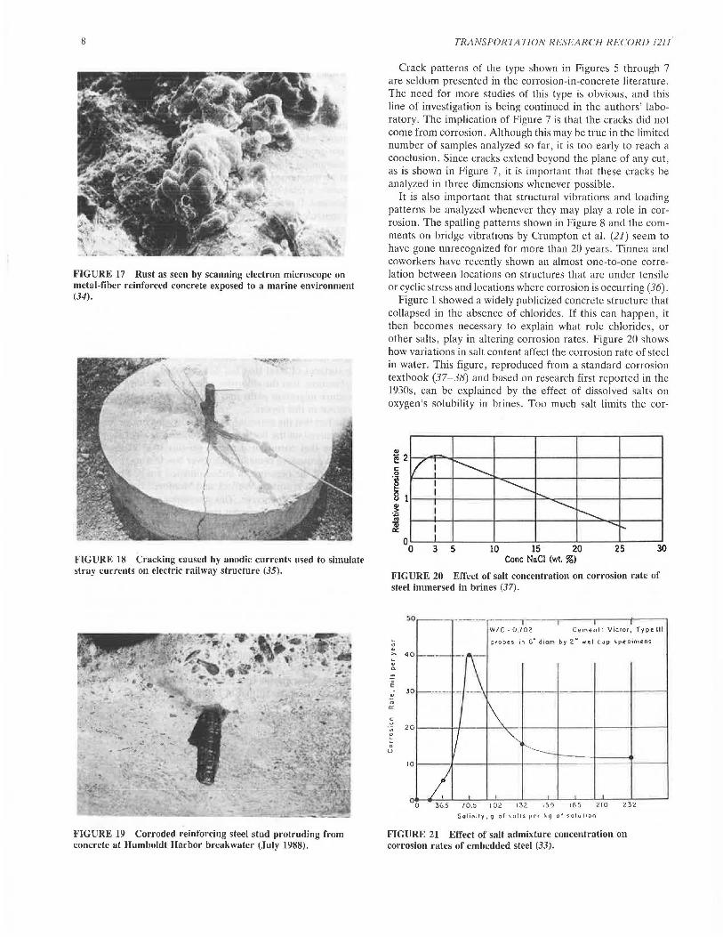
FIGURE 14 Stalactites formed from water runoff from reinforced highway bridge in Edmond, Oklahoma (January 1985).
FIGURE 15 Closeup of steel removed from bridge shown in Figure 14. Note localized corrosion and absence of corrosion at other locations on the same steel. Extensive corrosion was at bottom of steel as it was located in the bridge.
protective concrete adhering to the same rebar only millimeters away from the corroded area (25). Thus the chlorinecontaining salts at the corroded location penetrated into the crack and did not diffuse into the rest of the concrete, as sometimes happens (26-29).
Stalactite formations indicate locations where relatively large amounts of water have permeated a concrete structure (Figure 14). Figure 15 shows the corrosion pattern found on the reinforcing steel removed from the Oklahoma highway bridge shown in Figure 14. The bottom of the steel, as it was located in the bridge, appears as the extensively corroded, or pitted, top of the steel in Figure 15. Portions of the steel are extensively corroded, while other portions of the same steel are uncorroded.
Many writers claim that this uncorroded area is due to a cathodic protection effect caused by the local corrosion (10,16). This is inconsistent with modern, mixed-potential corrosion theory as discussed in virtually all corrosion textbooks. Vir-
Borgard et al.
TABLE 2 VARIATIONS IN CHLORIDE
D80i.t·1 Chloride Difference .,, (t;.~
7
( Lt1s/ 1~ dt) Hi l)h (; n1:.:1es) (Lbs/~,{) (-' - .... I 00 ) ,",
H1or1 Low Low
9 50 1.05 a a:. 905 1.) '·'·'
() 75 5 BB 0.45 " 43 1306 ..J
0.75 to 1.5 I 1 19 9. 18 I 2.01 556
. 5 t.c: 2.25 4 34 0 31 4.03 i 40.:: '
tually all corrosion of carbon steel occurs with the simultaneous, oxidation of metal and reduction of a chemically reducible species, usually dissolved oxygen, at the same location, at the same time (30,31).
The SEM was used to analyze the steel in Figure 15 the same way the steel in Figure 13 was analyzed. Adherent cementitious material on the reinforcing steel had virtually no chlorine, as did the uncorroded steel. The only location where chlorine was present in significant amounts was where corrosion had occurred.
The SEM is capable of showing chemical differences on a microscopic scale, but most concrete research reports chlorine analyses on a larger scale using wet chemical analysis. Table 2 shows the variations in chlorine analysis taken from the same bridge deck core at locations 5 cm (2 in.) apart. These analyses confirm the wide variations in salt ingress detected by the SEM. Since most salt permeates concrete along cement paste-aggregate interfaces (32) or cracks (23), it is easy to understand why corrosion of reinforcing steel is normally localized, as that shown in Figures 13 and 15.
DISCUSSION OF RESULTS
The corroded parking garages shown in Figures 3 and 4 were the result of a lack of protective cover on the steel. This lack of cover can be caused by structural cracking (Figure 3) or poor workmanship (Figure 4).
One of the most widely reported assumptions about North American corrosion in the concrete literature is the idea that corrosion, promoted by the ingress or diffusion of chloride ions from surface deicing salts , is responsible for much of the cracking of highway bridge decks and similar structures. Most reports on this phenomenon cite early work by Stratfull and coworkers, who established that elevated chlorine levels were invariably associated with corrosion of reinforcing steel on the California highway structures under investigation. The collapse of the Berlin Congress Hall was not due to the presence of chlorides (15), and it is therefore very different from the parking garage problems shown in Figures 2 through 4. The parking garages in Figures 2 through 4 are very similar in many ways to the highway bridges discussed by many authors (JO) .
There can be no question that chlorine, from marine environments or from deicing salts , is associated with most highway structures that develop extensive corrosion problems. Few authors have questioned whether chlorine was causative of corrosion or whether the detected chlorine was present as
7
an artifact along with other , possibly more important , factors (10) .
The limited results presented in this report cannot answer this overall question. Nonetheless, they do indicate that corrosion can occur on structures exposed to deicing salts in locations where general salt permeation into the structures has not occurred. Thus the idea that corrosion follows general permeation of chloride-containing salts into these structures must be questioned, and the usefulness of studies of overall permeation rates of chlorides into concrete (26-29) must be questioned. It is much more likely that chloride ions migrate into concrete following cement paste-aggregate interfaces (32) or cracks (25). This was suggested by U.S. Navy research that was, unfortunately, never completed (33) and by the Kansas highway research summarized in Table 2.
The evidence presented in this report suggests that deicing salts can be found at corroded locations on reinforcing steel but that these salts are not always present. The lack of chlorides can be explained by the fact that chloride salts are highly ionic and, therefore, water soluble. Thus, they could presumably be carried away by flowing water. Unfortunately, this does not explain why chlorides are not present on the cementitious material clinging to uncorroded reinforcing steel or on the surfaces of steel that has not corroded. The alternative explanation, that the chlorides , when present, have followed moisture migration paths into the concrete, seems to fit the evidence in this report.
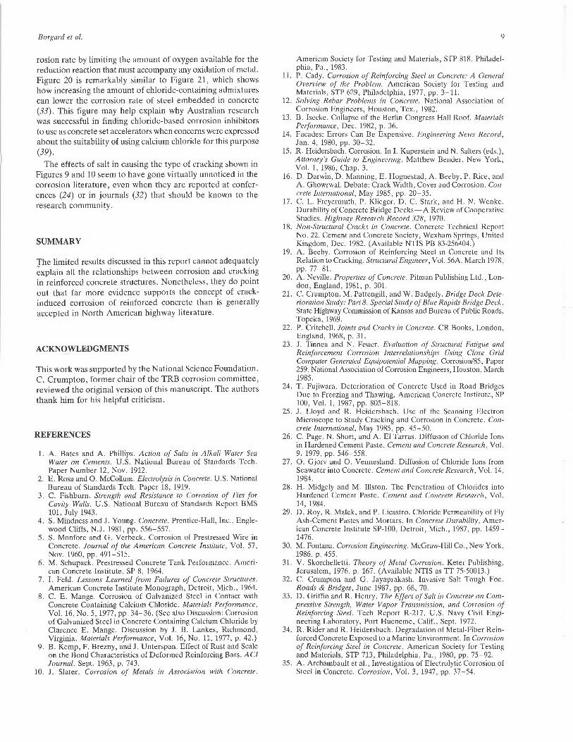
The fact that the corrosion on the Oklahoma bridge (Figure 15) occurred on the bottom of the reinforcing steel supports the idea that corrosion occurred on this steel at locations where a protective cementitious cover was lacking, probably because of the presence of unconsolidated voids. Figure 16, from a 1960s report by Verbeck and Monfore (5), shows rust filling a cavity in concrete. This macrophotograph has many similarities to the voluminous rust found on cracked, metalfiber reinforced concrete (Figure 17) (34). Thus the idea that corrosion occurs in cracks and voids is not new, and there is experimental evidence to support the idea.
Figure 18 shows an early (1940s) experiment in which excess anodic current caused corrosion and cracking on a reinforced concrete laboratory sample (35) . A careful review of the literature has failed to identify any laboratory or field investigations in which cracking due to the corrosion of embedded steel has occurred in the absence of externally applied electric currents . Figure 19 shows corroded steel protruding from concrete in a marine environment. Although the steel is extensively corroded, no cracking has occurred in the adjacent concrete. Most marine concrete locations can produce dozens of examples similar to that in Figure 19.
FIGURE 16 Rust filling void in concrete (5) .
8
FIGURE 17 Rust as seen by scanning electron microscope on metal-fiber reinforced concrete exposed to a marine environment (34).
FIGURE 18 Cracking caused by anodic currents used to simulate stray currents on electric railway structure (35).
FIGURE 19 Corroded reinforcing steel stud protruding from concrete at Humboldt Harbor breakwater (July 1988).
TRANSPORTATION RESEARCH RECORD 1211
Crack patterns of the type shown in Figures 5 through 7 are seldom presented in the corrosion-in-concrete literature. The need for more studies of this type is obvious, and this line of investigation is being continued in the authors' laboratory. The implication of Figure 7 is that the cracks did not come from corrosion. Although this may he true in the limited number of samples analyzed so far, it is too early to reach a conclusion. Since cracks extend beyond the plane of any cut, as is shown in Figure 7, it is important that these cracks be analyzed in three dimensions whenever possible.
It is also important that structural vibrations and loading patterns be analyzed whenever they may play a role in corrosion. The spalling patterns shown in Figure 8 and the comments on bridge vibrations by Crumpton et al. (21) seem to have gone unrecognized for more than 20 years. Tinnea and coworkers have recently shown an almost one-to-one correlation between locations on structures that are under tensile or cyclic stress and locations where corrosion is occurring (36).
Figure 1 showed a widely publicized concrete structure that collapsed in the absence of chlorides. If this can happen, it then becomes necessary to explain what role chlorides, or other salts, play in altering corrosion rates. Figure 20 shows how variations in salt content affect the corrosion rate of steel in water. This figure, reproduced from a standard corrosion textbook (37-38) and based on research first reported in the 1930s, can be explained by the effect of dissolved salts on oxygen's solubility in brines. Too much salt limits the cor-
-I/ i ~ I
I ~ I !'..... I ............... I r---......_ J
I ....... ~ I
3 5 10 15 20 25 30 Cone NaCl (wt. %)
FIGURE 20 Effect of salt concentration on corrosion rate of steel immersed in brines (37).
" u ~
u
"' E
u
" "' c 0
0
0
u
so - ---- ·---i ---.-- --.----t------, W/C ~ 0 .702 Cemenl: Victor, Type Ill
probes in G" diam by 2" wet cup specimens
40 - - -
30 ·- ---1----1-----1
20
10 1----·l---+---~----+---r--~1-----1
0 365 70.5 102 132 159 185 210 232
Solinity,g of salls per kg of solul1on
FIGURE 21 Effect of salt admixture concentration on corrosion rates of embedded steel (33).
Borgard el al.
rosion rate by limiting the amount of oxygen available for the reduction reaction that must accompany any oxidation of metal. Figure 20 is remarkably similar to Figure 21, which shows how increasing the amount of chloride-containing admixtures can lower the corrosion rate of steel embedded in concrete (33). This figure may help explain why Australian research was successful in finding chloride-based corrosion inhibitors to use as concrete set accelerators when concerns were expressed about the suitability of using calcium chloride for this purpose (39).
The effects of salt in causing the type of cracking shown in Figures 9 and 10 seem to have gone virtually unnoticed in the corrosion literature, even when they are reported at conferences (24) or in journals (32) that should be known to the research community.
SUMMARY
The limited results discussed in this report cannot adequately ~xplain all the relationships between corrosion and cracking in reinforced concrete structures. Nonetheless, they do point out that far more evidence supports the concept of crackinduced corrosion of reinforced concrete than is generally accepted in North American highway literature.
ACKNOWLEDGMENTS
This work was supported by the Na ti on al Science Foundation. C. Crumpton, former chair of the TRB corrosion committee, reviewed the original version of this manuscript. The authors thank him for his helpful criticism.
REFERENCES
1. A. Bates and A. Phillips. Action of Salts in Alkali Water Sea Water on Cements. U.S. National Bureau of Standards Tech. Paper Number 12, Nov. 1912.
2. E. Rosa and 0. McCollum. Electrolysis in Concrete. U.S. National Bureau of Standards Tech. Paper 18, 1919.
3. C. Fishburn. Strength and Resistance to Corrosion of Ties for Cavity Walls. U.S. National Bureau of Standards Report BMS 101, July 1943.
4. S. Mindness and J. Young. Concrete. Prentice-Hall, Inc., Englewood Cliffs, N.J. 1981, pp. 556-557.
5. S. Monfore and G. Verbeck. Corrosion of Prestressed Wire in Concrete. Journal of the American Concrete Institute, Vol. 57, Nov. 1960, pp. 491-515.
6. M. Schupack. Prestressed Concrete Tank Performance. American Concrete Institute, SP 8, 1964.
7. I. Feld. Lessons Learned from Failures of Concrete Structures. American Concrete Institute Monograph, Detroit, Mich., 1964.
8. C. E. Mange. Corrosion of Galvanized Steel in Contact with Concrete Containing Calcium Chloride. Materials Performance, Vol. 16, No. 5, 1977, pp. 34-36. (See also Discussion: Corrosion of Galvanized Steel in Concrete Containing Calcium Chloride by Clarence E. Mange. Discussion by J. B. Lankes, Richmond, Virginia. Materials Performance, Vol. 16, No. 11, 1977, p. 42.)
9. B. Kemp, F. Brezny, and J. Unterspan. Effect of Rust and Scale on the Bond Characteristics of Deformed Reinforcing Bars. AC! Journal, Sept. 1963, p. 743.
10. J. Slater. Corrosion of Metals in Association with Concrete.
9
American Society for Testing and Materials, STP 818, Philadelphia, Pa., 1983.
11. P. Cady. Corrosion of Reinforcing Steel in Concrete: A General Overview of the Problem. American Society for Testing and Materials, STP 629, Philadelphia, 1977, pp. 3-11.
12. Solving Rebar Problems in Concrete. National Association of Corrosion Engineers, Houston, Tex., 1982.
13. B. Isecke. Collapse of the Berlin Congress Hall Roof. Materials Performance, Dec. 1982, p. 36.
14. Facades: Errors Can Be Expensive. Engineering News Record, Jan. 4, 1980, pp. 30-32.
15. R. Heidersbach. Corrosion. In I. Kuperstein and N. Salters (eds.), Attorney's Guide to Engineering. Matthew Bender, New York, Vol. 1, 1986, Chap. 3.
16. D. Darwin, D. Manning, E. Hognestad, A. Beeby, P. Rice, and A. Ghowrwal. Debate: Crack Width, Cover and Corrosion. Concrete International, May 1985, pp. 20-35.
17. C. L. Freyermuth, P. Klieger, D. C. Stark, and H. N. Wenke. Durability of Concrete Bridge Decks-A Review of Cooperative Studies. Highway Research Record 328, 1970.
18. Non-Structural Cracks in Concrete. Concrete Technical Report No. 22. Cement and Concrete Society, Wexham Springs, United Kingdom, Dec. 1982. (Available NTIS PB 83-256404.)
19. A. Beeby. Corrosion of Reinforcing Steel in Concrete and Its Relation to Cracking. Structural Engineer, Vol. 56A, March 1978, pp. 77-81.
20. A. Neville. Properties of Concrete. Pitman Publishing Ltd., London, England, 1981, p. 301.
21. C. Crumpton, M. Pattengill, and W. Badgely. Bridge Deck Deterioration Study: Part 8. Special Study of Blue Rapids Bridge Deck. State Highway Commission of Kansas and Bureau of Public Roads, Topeka, 1969.
22. P. Critchell. Joints and Cracks in Concrete. CR Books, London, England, 1968, p. 31.
23. J. Tinnea and N. Feuer. Evaluation of Structural Fatigue and Reinforcement Corrosion Interrelationships Using Close Grid Computer Generated Equipotential Mapping. Corrosion/85, Paper 259. National Association of Corrosion Engineers, Houston, March 1985.
24. T. Fujiwara. Deterioration of Concrete Used in Road Bridges Due to Freezing and Thawing. American Concrete Institute, SP 100, Vol. 1, 1987, pp. 805-818.
25. J. Lloyd and R. Heidersbach. Use of the Scanning Electron Microscope to Study Cracking and Corrosion in Concrete. Concrete International, May 1985, pp. 45-50.
26. C. Page, N. Short, and A. El Tarras. Diffusion of Chloride Ions in Hardened Cement Paste. Cement and Concrete Research, Vol. 9, 1979, pp. 546-558.
27. 0. Gjorv and 0. Vennesland. Diffusion of Chloride Ions from Seawater into Concrete. Cement and Concrete Research, Vol. 14, 1984.
28. H. Midgely and M. Illston. The Penetration of Chlorides into Hardened Cement Paste. Cement and Concrete Research, Vol. 14, 1984.
29. D. Roy, R. Malek, and P. Licastro. Chloride Permeability of Fly Ash-Cement Pastes and Mortars . In Concrete Durability, American Concrete Institute SP-100, Detroit, Mich., 1987, pp. 1459-1476.
30. M. Fontana. Corrosion Engineering. McGraw-Hill Co., New York, 1986, p. 455.
31. V. Skorchelletti. Theory of Metal Corrosion. Keter Publishing, Jerusalem, 1976, p. 167. (Available NTIS as TT 75-50013.)
32. C. Crumpton and G. Jayaprakash. Invasive Salt Tough Foe. Roads & Bridges, June 1987, pp. 68, 70.
33. D. Griffin and R. Henry. The Effect of Salt in Concrete on Compressive Strength, Water Vapor Transmission, and Corrosion of Reinforcing Steel. Tech Report R-217. U.S. Navy Civil Engineering Laboratory, Port Hueneme, Calif., Sept. 1972.
34. R. Rider and R. Heidersbach. Degradation of Metal-Fiber Reinforced Concrete Exposed to a Marine Environment. In Corrosion of Reinforcing Steel in Concrete, American Society for Testing and Materials, STP 713, Philadelphia, Pa., 1980, pp. 75-92.
35. A. Archambault et al., Investigation of Electrolytic Corrosion of Steel in Concrete. Corrosion, Vol. 3, 1947, pp. 37-54.
10
36. J. Tinnea. Tinnea Associates, Seattle, Wash., private communication, June 1988.
37. H . Uhlig and W. Revie. Corrosion and Corrosion Control. John Wiley and Sons, Inc., New York, 1985 , p. 108.
38. H. Uhlig. Corrosion Handbook. John Wiley and Sons, Inc., New York, 1948, p. 131.
39. M. Arber and H. Vivian. Inhibition ot the Corrosion of Steel Embedded in Mortar. Australian Journal of Applied Science, Vol: 12, No. 3, Sept. 1961, pp. 339-347.
Publication of this paper sponsored by Committee on Corrosion.
DISCUSSION
CARL F. CRUMPTON
4728 S. W. 18th Terrace, Topeka, Kans. 66604.
In their summary, authors Borgard et al. conclude that "far more evidence supports the concept of crack-induced corrosion of reinforced concrete than is generally accepted in North American highway literature." Having been a user of and a contributor to the North American highway literature for many years, and having faced the bridge deck deterioration problem in Kansas since the 1950s, I do not agree with that statement. Because I was acknowledged by the authors as a reviewer of the original version of the manuscript, and have 30 years of experience with the problem, I would like to make my opinions clear. The presence of vertical cracks in concrete has long been recognized and accepted without much question as a significant factor in the corrosion of embedded reinforcing steel in concrete. Authors Borgard et al. admit that the idea that corrosion occurs in cracks and voids is not new.
Reinforcing steel in concrete bridge decks and other concrete components of bridges was corroding long before any deicing salts were used on roads, streets, or bridges. This corrosion was generally associated with moisture and oxygen reaching the steel through pre-existing cracks or other channels in the concrete. The cracks, which may have been structural, temperature-related resistance to subsidence, or caused by early drying shrinkage, alkali-aggregate reaction, freezethaw action, and so on, became ready conduits for water and air to reach and corrode the steel. Highway engineers and scientists recognized and accepted this. Bridge designers and materials engineers concentrated on reducing the number and width of the cracks to minimize the ingress of moisture to the reinforcing steel.
The advent of the use of chloride deicing salts on roads and bridges across the snowbelt states made it possible to clear pavements soon after a snow or ice storm. With that development, however, came serious bridge deck deterioration problems. Authors Borgard et al. acknowledge this in their paper. Deicing salt did not invent corrosion of reinforcing steel and deterioration of concrete but it certainly accelerated their growth in new and old bridges that were not previously exhibiting such problems. Pre-existing cracks were still an important avenue for water and oxygen to reach the reinforcing steel, but the fact that the water was now salty and contained chloride ions accelerated corrosion.
There is considerable highway literature available addressing cracking in relation to corrosion . NCHRP Synthesis of
TRANSPORTATION RESEARCH RECORD 1211
Highway Practice 4 (1) and 57 (2) both summarize literature related to concrete bridge deck durability. Both note the influence of cracks in allowing access of moisture, oxygen, and chloride ions to the reinforcement. NCH RP Synthesis of Highway Practice 4 (1) contains an illustration (Figure 2) that was modified from an earlier version published in a Missouri study (3). It shows a crack over the reinforcing steel and it is noted in the figure that salt solutions in the crack accelerate corrosion. NCH RP Synthesis uf Highwuy Pruclh:e 57 (2) wnlains the following statement: "It is. generally acknowledged that cracks perpendicular to the reinforcing steel will hasten corrosion of intercepted bars by facilitating the ingress of moisture, oxygen, and chloride ions to the reinforcement." Later in the same paragraph it is stated: "Cracks that follow the line of reinforcing bar are much more serious." Authors Borgard et al. say the same thing but cite an American Concrete Institute source (from Kansas) published six years after NCHRP Synthesis of Highway Practice 57 was published.
Nevertheless, it is not these vertical cracks that highway researchers believe result from corrosion products from the reinforcing steel, although a few do. It is instead the undulating, subhorizontal cracks at or near the general level of the top mat of reinforcing steel that are associated with the formation of delaminations and spalls in the concrete that are of the most concern. It is those roughly horizontal delamination cracks that are considered to be initially created by corrosion of the reinforcing steel. In my early field and laboratory studies during the 1950s and 1960s, I considered many possible alternative causes for those delaminations . The preponderance of evidence, however, continued to point toward deicing salt chloride ions and reinforcing steel corrosion as the most probable initial causes of the large area delamination type of cracking. Many other petrographers, corrosion engineers, and concrete researchers in the United States and Canada were independently arriving at the same conclusions at about the same time.
Concrete researchers were not mystified by, nor did they ignore the influence of, vertical cracks on corrosion. The importance of vertical cracks was readily accepted . What was puzzling, however, was that only a few of the visible vertical cracks seemed to be associated with delaminations and spalling. Many deck areas were also found with delaminations that were not associated with vertical cracks that allowed moisture and deicing salts ready access to the reinforcing steel. This was reported in 1965 in Report 1 of the studies on Durability of Concrete Bridge Decks being conducted cooperatively by the Portland Cement Association (PCA), the Bureau of Public Roads, and a number of states (4). Report 1 dealt with bridges in Kansas-studies with which I was associated. Therein it was stated that only a small percentage of observed cracks was associated with serious forms of deterioration. In some cases, surface spalls and delaminations were associated with transverse or longitudinal cracks, but in others no such association was present.
Kansas Bridge Deck Deterioration Studies Part 8, published in 1968 (5) contained a series of detailed maps giving reinforcing steel location and depth, all visible transverse and longitudinal cracks, and the location of delaminations and spalls. It is easy to see in those maps (Figures 6, 8-15) that many delaminations and "hollow planes" were not associated with surface cracks. It was also noted that there were as many
Borgard et al.
cracks in areas of little delamination as there were in areas of extensive delamination. In the conclusions we noted that vertical cracks over the reinforcing steel allowed water and deicing salt to penetrate to the shallow steel. Rusting of the steel and freeze-thaw damage followed. Observations of delaminations not associated with vertical cracks repeated in state after state and province after province led to the conclusion that the lack of vertical cracks did not preclude chloride ions from permeating the concrete and reaching the reinforcing steel. I do not believe, however, that anyone ignored the importance of cracks.
Authors Borgard et al. cited my report (5) as their Reference 21. They concluded from my report statements that the spalling of the decks (and presumably the far greater area of delaminations) was caused by loading and vibration-related fatigue cracking of the bridge deck. We considered such possibilities when the study was under way. Kansas bridge designers made thorough recalculations of the design data and the known construction and post-construction data available. They also made a model of the deck and its supports but found little or no convincing evidence that fatigue was much of a factor in creating the extensive delaminations or spalls. PCA designers made their own calculations independently and came to the same conclusion. Furthermore, study of hundreds of decks showed that the pattern of spalls and delaminations varied whether the deck was flexible or not.
If vibrations and deflections were the major causes of the delaminations, there should not be miles of delaminations in continuously reinforced concrete pavements built on sound bases. There again, the major evidence points to corrosion of the reinforcing steel by deicing salts as the major culprit in creating the delaminations. Vertical cracks in the pavements are recognized as one conduit for deicing salt meltwater to contact the continuous reinforcing steel. Even 12-in.-thick mesh reinforced concrete pavements are plagued with delaminations and surface spalls where the mesh inadvertently gets too near the top concrete surface. This certainly is not fatigue from loads and vibrations. If vibrations and loading were the major causes of delaminations, the use of epoxy-coated reinforcing steel would not have helped. In fact, the problem should have become worse because of the reduction in bond between epoxy-coated steel and concrete. Experience shows that in bridge decks, epoxy coating of all the reinforcing steel has resulted in savings through lowered maintenance costs and expected longer deck life in areas in which chloride deicing salts are used.
JI
REFERENCES
1. Orrin Riley. NCHRP Synthesis of Highway Practice 4: Concrete Bridge Deck Durability. HRB, National Research Council, Washington, D.C., 1970.
2. David G. Manning. NCHRP Synthesis of Highway Practice 57: Durability of Concrete Bridge Decks. TRB, National Research Council, Washington, D.C., May 1979.
3. A Study of Deterioration in Concrete Bridge Decks. Missouri State Highway Department and Bureau of Public Roads Investigation 59-2A, 1965.
4. Durability of Concrete Bridge Decks. A Cooperative Study, State Highway Commission of Kansas, Bureau of Public Roads and Portland Cement Association, Report 1, 1965.
5. Carl F. Crumpton, Maurice G. Pattengill, and William A. Badgley. Bridge-Deck Deterioration Study, Part 8, Special Study of Blue Rapids Bridge Deck. State Highway Commission of Kansas and Federal Highway Administration, 1969.
AUTHORS' CLOSUI;{E
We welcome Carl Crumpton's comments and appreciate his continuing interest in our manuscript. Unfortunately, we still disagree. The comments on the structure with delaminations and spalls (Figure 8 in our manuscript) are direct quotes from the Kansas report that Crumpton coauthored. The bridge did vibrate, at least according to the report. If calculations said it did not vibrate, then either the calculations or the field observations in the report by Crumpton and coauthors must have been in error.
Since our manuscript was prepared last fall, a report on highway bridges in the New York City area has appeared that supports our conclusions (1). The authors of that report show that depth of cover is the single most important factor affecting why corrosion occurs on some bridges and does not on others of almost identical design and usage history. Delaminations can be caused by flexure or by wheel loading, and we assume this is the reason why wheel loading or structural vibrations can lead to salt ingress and corrosion. Note that most steel in the vicinity of delaminations (Figure 11) is uncorroded. This is common; general corrosion of reinforcing steel is much less common in our nationwide experience.
REFERENCE
1. B. Burkowski and J. Engloi. Concrete International, Nov. 1988, pp. 25-33.