corp. 9418–l9 revised 04–2003 - heating and air parts ... service.pdf · lennoxoemparts.com...
TRANSCRIPT

LENNOXOEMPARTS.COM
Page 1�1994 Lennox Industries Inc.
Litho U.S.A.
Corp. 9418–L9 G20Service Literature Revised 04–2003
G20 SERIES UNITS
I−INTRODUCTION/APPLICATION
G20 and G20E series units are mid−efficiency gas fur�
naces manufactured with Duracurvet heat exchangers
formed of either cold rolled or aluminized steel. G20 units
come in heating capacities of 50,000 to 150,000 Btuh and
cooling applications up to 6 tons. Refer to Engineering
Handbook for proper sizing.
Units are factory supplied for use with natural gas. A kit is
available for conversion to LPG operation. The G20 unit is
equipped with a standing pilot. G20E units use an elec�
tronic ignition. G20X units use electronic ignition and meet
the California Nitrogen Oxides (NOx) Standards and Cali�
fornia Seasonal Efficiency requirements. G20X series
units use only natural gas. All units use a redundant gas
valve to assure safety shut−off as required by A.G.A.
Featured on G20 series is a burner box damper assembly
located on the intake side of the burners. A damper door in
the burner box shuts during unit off cycles to retain heat in
the unit. A damper prove switch ensures that damper is
open before gas valve is energized. Since the G20 fur�
naces have atmospheric burners there is no induced draft
motor. All G20 units use a draft diverter which allows the
use of standard single wall vent connectors.
This manual is divided into sections which discuss the ma�
jor components, electronic ignition module, maintenance
and operation sequences.
All specifications in this manual are subject to change.
SPECIFICATIONS(continued on next page)
Model No.
Input Btuh
Output Btuh
*A.F.U.E.
Flue connection (in. diameter)
Temperature rise range
High static certified by A.G.A.(in wg.)
Gas piping sizeI.P.S. (in.)
Blower wheel nominal diameter x width (in.)
Blower motor hp
Number and size of filters (in.)
Electrical characteristics
Natural
LPG
**Optional LPG Conversion Kit
G20Q2−50 G20Q3−50 G20Q3−75 G20Q4−75 G20Q3/4−100
50,000
40,000
77.0%
4
25−55
.50
1/2
1/2
9 x 7
1/4
120 volts � 60 hertz � 1 phase (less than 12 amps) � All Models
1, 1−1/2, 2Tons of cooling (add−on)
LB−62384DA
50,000
40,000
77.0% 77.0% 77.0% 78.0%
75,000
59,000
75,000
60,000
100,000
79,000
4 4 4 5
25−55 35−65 25−55 35−65
.50 .50 .50 .50
1/2
1/2
1/2
1/2
1/2
1/2
1/2
1/2
10 x 7 10 x 7 10 x 8 10 x 8
1/3 1/3 1/2 1/2
(1) 16 x 25 x 1
2−1/2 or 3 3−1/2 or 4 3, 3−1/2, 42−1/2 or 3
*Annual Fuel Utilization Efficiency based on D.O.E. test procedures and according to F.T.C. labeling requirements. Isolated combustion system rating for non−weatherized furnaces.**LPG kit must be ordered extra for field changeover.

LENNOXOEMPARTS.COM
Page 2
Model No.
Input Btuh
Output Btuh
*A.F.U.E.
Flue connection (in. diameter)
Temperature rise range
High static certified by A.G.A.(in wg.)
Gas piping sizeI.P.S. (in.)
Blower wheel nominal diameter x width (in.)
Blower motor hp
Number and size of filters (in.)
Electrical characteristics
Natural
LPG
**Optional LPG Conversion Kit
G20Q5/6−100 G20Q3−125 G20Q4/5−125 G20Q5/6−150
100,000
79,000
78.0%
5
.75
1/2
1/2
12 x 12
3/4
120 volts � 60 hertz � 1 phase (less than 12 amps) � All Models
5 or 6Tons of cooling (add−on)
LB−62384DA
LB−62384DB
125,000
100,000
77.0% 78.0% 78.0%
80.0%
125,000
99,000
150,000
115,000
50,000
39,000
6 6 6
70−100 35−65 40−70
25−55
.50 .50 .50
.50
1/2
1/2
1/2
1/2
1/2
1/2
1/2
1/2
10 x 8 12 x 12 12 x 12
1/3 3/4 3/4
1/4
(1) 20 x 25 x 1
(1) 16 x 25 x 1
2−1/2 or 3 5 or 64 or 5
Model No.
Input Btuh
Output Btuh
*A.F.U.E.
Flue connection (in. diameter)
Temperature rise range
High static certified by A.G.A.(in wg.)
Gas piping sizeI.P.S. (in.)
Blower wheel nominal diameter x width (in.)
Blower motor hp
Number and size of filters (in.)
Electrical characteristics
Natural
LPG
**Optional LPG Conversion Kit
G20Q3E−50 G20Q3E−75 G20Q4E−75 G20Q3/4E−100
50,000
4
25−55
.50
1/2
1/2
10 x 7
1/3
120 volts � 60 hertz � 1 phase (less than 12 amps) � All Models
Tons of cooling (add−on)
80.0% 80.0%
75,000
59,000
100,000
78,000
4 4 5
35−65
.50 .50 .50
1/2
1/2
1/2
1/2
1/2
1/2
10 x 7 10 x 8
1/3 1/2
2−1/2 or 3 3−1/2 or 4
25−55
Output Btuh��X" models
*A.F.U.E.��X" models
California Seasonal Efficiency��X" models
39,000
80.0%
75.1%
4
9 x 7
1, 1−1/2, 2
39,000
80.0%
39,000
80.0%
74.2%
2−1/2 or 3
59,000
80.0%
76.0%
80.0%
75,000
60,000
80.0%
60,000
75.3%
25−55
80.0%
78,000
76.0%
35−65
10 x 8
1/2
3, 3−1/2, 4
SPECIFICATIONS
G20Q5/6E−100
LB−62384DB
80.0%
100,000
78,000
25−55
.75
1/2
1/2
3/4
(1) 20 x 25 x 1
Model No.
Input Btuh
Output Btuh
*A.F.U.E.
Flue connection (in. diameter)
Temperature rise range
High static certified by A.G.A.(in wg.)
Gas piping sizeI.P.S. (in.)
Blower wheel nominal diameter x width (in.)
Blower motor hp
Number and size of filters (in.)
Electrical characteristics
Natural
LPG
*Optional LPG Conversion Kit
G20Q3E−125 G20Q4/5E−125 G20Q5/6E−150
125,000
6
70−100
.50
1/2
1/2
10 x 8
1/3
120 volts � 60 hertz � 1 phase (less than 12 amps) � All Models
Tons of cooling (add−on)
80.0%
125,000
97,000
6 6
35−65
.50 .50
1/2
1/2
1/2
1/2
12 x 12 12 x 12
3/4 3/4
2−1/2 or 3 5 or 6
Output Btuh��X" models
*A.F.U.E.��X" models
California Seasonal Efficiency��X" models
78,000
80.0%
75.0%
5
12 x 12
5 or 6
95,000
79.5%
95,000
79.5%
77.0%
4 or 5
97,000
80.0%
76.1%
80.0%
150,000
116,000
80.0%
116,000
75.7%
40−70
*Annual Fuel Utilization Efficiency based on D.O.E. test procedures and according to F.T.C. labeling requirements. Isolated combustion system rating for non−weatherized furnaces.**LPG kit must be ordered extra for field changeover.
G20Q2E−50
(continued from previous page)
♦G20Q3X−75♦G20Q2X−50 ♦G20Q3X−50 ♦G20Q4X−75
♦Not available with LPG.
♦G20Q5/6X−150♦G20Q4/5X−125♦G20Q3X−125♦G20Q5/6X−100
♦G20Q3/4X−100

LENNOXOEMPARTS.COM
Page 3
FIGURE 1
PARTS IDENTIFICATION(G20E Units Shown)
HEATEXCHANGER
DRAFTHOOD
UPPER ACCESSPANEL
BURNERS
BURNER BOX
IGNITIONCONTROL
(G20E &G20XUnits Only)
BLOWER
GASMANIFOLD
BURNER BOXDAMPER ASSEMBLY
REAR BAFFLE
TOP STRIP
LIMITCONTROL
CABINET
CONTROL BOX
ROLL−OUTSWITCH
VENT SAFETYSHUT−OFFSWITCH
CABINET CAP
GAS VALVE
PILOT/ELECTRODEASSEMBLY
DAMPERMOTOR/GEAR
PATCH PLATE
PATCH PLATE
SPRING
DAMPERPROVE SWITCH
PROVESWITCH COVER
OBSERVATION PORTCOVER
ROLL−OUTSWITCH
PILOTLIGHTING ROD
(G20 UNITS ONLY)
DAMPER
PILOT PATCHPLATE
DAMPERBOX
DAMPER BOX PARTS ARRANGEMENT(G20 Units Shown)
FIGURE 2
DAMPER OPENING
G20 CONTROL BOX � FRONT VIEW
DAMPERDOOR
BLOWER
BCC2−1CONTROL
A15
TRANSFORMERT1
FIGURE 3
DOORINTERLOCK
S51
II−UNIT COMPONENTS
A−Control Box (Figure 3)
On G20 series units the unit control box is located in the
blower compartment between the burner box and the
blower housing. The hinged control box can be lowered for
service access by removing two securing screws, one lo�
cated on either side. At the top right corner of the control
box is the door interlock switch (S51).
Housed in the control box are the unit transformer (T1) and
the BCC2−1 blower control (A15).

LENNOXOEMPARTS.COM
Page 4
1− Control Transformer (T1)
A transformer located inside the control box provides pow�
er to the low voltage section of the unit. Transformers on all
models are rated 30VA with a 120V primary and a 24V sec�
ondary.
2− BCC2−1 through BCC3−2 Blower Control (A15)
All G20 units utilize the BCC blower control. The BCC is a
printed circuit board which controls the blower and moni�
tors primary limit and gas valve operation. The control has
a non−adjustable, factory preset �on" fan timing. Fan �off"
timings are adjustable. The board is divided into two sec�
tions, 120 and 24VAC. Line voltage comes into the board
on the 120VAC side. See figure 4.
�CAB" and �XFMR " send 120VAC to the damper motor
and transformer, respectively. The active cooling and
heating blower speed terminals and three dummy �D" ter�
minals are located on the 120VAC side of the BCC. Also
located on the 120VAC side of the control are neutral ter�
minals and a terminal for accessories such as an electron�
ic air cleaner. The �HSI" terminal is not used.
24VAC comes from the transformer into terminal �24V" onthe 24VAC side of the BCC. Thermostat connections and
safety circuit terminals are also located on the 24VAC sideof the control. Fan �off" timings may be adjusted by chang�
ing the position of a jumper across terminal pins. Thermo�
stat terminal strips on early model BCC boards are remov�
able. Late model boards have permanent thermostat
strips.
Blower Speed Taps
Blower speed tap changes are made on the BCC
blower control board at the upper right corner. See fig�
ure 4. Unused speed taps must be secured to the
dummy �D" terminals on the BCC. The active heating
tap is connected to the �H" terminal and the active
cooling tap is connected to the �A" terminal.
Table 1 shows the blower motor tap colors for each
speed. To change a heating speed tap, turn off power,
remove existing speed tap from the �H" terminal and
place on �D" terminal. Next select new speed wire and
place on �H" terminal of the blower control and restore
power. Blower speed tap information can also be
found on the G20 unit wiring diagram.
TABLE 1
BLOWER SPEED SELECTION
BLOWER MOTOR LEAD
SPEED Q2−50 Q3−75
Q3−50, Q4−75Q3/4−100Q3−125
Q5/5−100Q4/5−125Q5/6−150
LOW RED RED RED
MEDIUM LOW − YELLOW YELLOW
MEDIUM YELLOW − BLUE
MEDIUM HI − BROWN BROWN
HIGH BLACK BLACK BLACK
FIGURE 4
NEUTRALTERMINALS
ACCESSORYTERMINAL
THERMOSTAT TERMINAL STRIP (DETACHABLE ON EARLY BOARDS ONLY))
BLOWER TIMEADJUSTMENT
JUMPER
HEATINGSPEED TAPTERMINAL
COOLINGSPEED TAPTERMINAL
DUMMYTERMINALS
CONTINUOUS FANTERMINAL
MECH
ELECT
THERMOSTAT JUMPER(Electronic or Mechanical)
Heat Anticipator SettingsBeginning with the BCC3−2 series, a 3 pin jumper hasbeen installed on the board next to the removable 24Vterminal strip to account for both programmable andelectromechanical thermostat usage in the field. Forelectromechanical thermostat, position the jumper overthe middle and bottom pin labeled "MECH." Set the heatanticipator setting to 0.65 amps for Honeywell valves or0.50 amps for White Rodgers valves. For programmable(electronic) thermostats, position the jumper over themiddle and top pin labeled "ELECT." Set the heat antici�pator setting to 0.1 amps.
BCC3−2 SHOWN
CAUTION
Electrostatic discharge can affect electronic components.Take precautions during furnace installation and service toprotect the furnace’s electronic controls. Precautions willhelp to avoid control exposure to electrostatic discharge byputting the furnace, the control and the technician at the sameelectrostatic potential. Neutralize electrostatic charge bytouching hand and all tools on an unpainted unit surface,such as the gas valve or blower deck, before performing anyservice procedure.
Fan Timings
LENNOXOEMPARTS.COM
Page 5
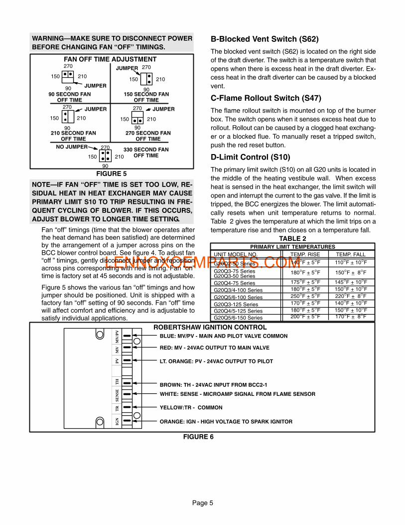
WARNING�MAKE SURE TO DISCONNECT POWER
BEFORE CHANGING FAN �OFF" TIMINGS.
90
270
150 210
90
150
270
210
90
270
150 210
90
270
150 210
90
270
150 210
JUMPER
JUMPER
JUMPER
JUMPER
NO JUMPER
90 SECOND FANOFF TIME
150 SECOND FANOFF TIME
210 SECOND FANOFF TIME
270 SECOND FANOFF TIME
330 SECOND FANOFF TIME
FIGURE 5
FAN OFF TIME ADJUSTMENT
NOTE�IF FAN �OFF" TIME IS SET TOO LOW, RE�
SIDUAL HEAT IN HEAT EXCHANGER MAY CAUSE
PRIMARY LIMIT S10 TO TRIP RESULTING IN FRE�
QUENT CYCLING OF BLOWER. IF THIS OCCURS,
ADJUST BLOWER TO LONGER TIME SETTING.
Fan �off" timings (time that the blower operates afterthe heat demand has been satisfied) are determinedby the arrangement of a jumper across pins on theBCC blower control board. See figure 4. To adjust fan�off " timings, gently disconnect jumper and repositionacross pins corresponding with new timing. Fan �on"time is factory set at 45 seconds and is not adjustable.
Figure 5 shows the various fan �off" timings and howjumper should be positioned. Unit is shipped with afactory fan �off" setting of 90 seconds. Fan �off" timewill affect comfort and efficiency and is adjustable tosatisfy individual applications.
B−Blocked Vent Switch (S62)
The blocked vent switch (S62) is located on the right side
of the draft diverter. The switch is a temperature switch that
opens when there is excess heat in the draft diverter. Ex�
cess heat in the draft diverter can be caused by a blocked
vent.
C−Flame Rollout Switch (S47)
The flame rollout switch is mounted on top of the burner
box. The switch opens when it senses excess heat due to
rollout. Rollout can be caused by a clogged heat exchang�
er or a blocked flue. To manually reset a tripped switch,
push the red reset button.
D−Limit Control (S10)
The primary limit switch (S10) on all G20 units is located in
the middle of the heating vestibule wall. When excess
heat is sensed in the heat exchanger, the limit switch will
open and interrupt the current to the gas valve. If the limit is
tripped, the BCC energizes the blower. The limit automati�
cally resets when unit temperature returns to normal.
Table 2 gives the temperature at which the limit trips on a
temperature rise and then closes on a temperature fall.
TABLE 2
UNIT MODEL NO. TEMP. RISE TEMP. FALL
G20Q2−50 Series
G20Q3−75 SeriesG20Q3−50 Series
G20Q4−75 Series
G20Q3/4−100 Series
G20Q5/6−100 Series
G20Q3−125 Series
G20Q4/5−125 Series
G20Q5/6−150 Series
140°F + 5°F 110°F + 10°F180°F + 5°F 150°F + 8°F175°F + 5°F 145°F + 10°F180°F + 5°F 150°F + 10°F250°F + 5°F 220°F + 8°F170°F + 5°F 140°F + 10°F180°F + 5°F 150°F + 10°F200°F + 5°F 170°F + 8°F
PRIMARY LIMIT TEMPERATURES
ROBERTSHAW IGNITION CONTROL
FIGURE 6
BLUE: MV/PV − MAIN AND PILOT VALVE COMMON
RED: MV − 24VAC OUTPUT TO MAIN VALVE
LT. ORANGE: PV − 24VAC OUTPUT TO PILOT
BROWN: TH − 24VAC INPUT FROM BCC2−1
WHITE: SENSE − MICROAMP SIGNAL FROM FLAME SENSOR
YELLOW:TR − COMMON
ORANGE: IGN − HIGH VOLTAGE TO SPARK IGNITOR
TR
IGN
SEN
SET
HM
VM
V/P
VP
V

LENNOXOEMPARTS.COM
Page 6
E−Robertshaw Electronic Ignition
The Robertshaw electronic ignition is an intermittent igni�
tion control module located on the vestibule panel. See fig�
ure 1. When there is a call for heat, the control generates a
spark to ignite the pilot, after which the control senses the
flame. If the flame current is too weak (less than 1 micro�
amp) the control will shutdown and de−energize the gas
valve. Flame current should be between 1 and 5 micro�
amps. See figure 6.
DANGER�SHOCK HAZARD. SPARK RELATED
COMPONENTS CONTAIN HIGH VOLTAGE. DISCON�
NECT POWER BEFORE SERVICING UNIT. THE IGNI�
TION CONTROL IS NOT FIELD REPAIRABLE. UN�
SAFE OPERATION MAY RESULT.
F−Gas Valve
The gas valves used on G20 series units have various
opening times.The G20E unit with electronic ignition uses
a Robertshaw gas valve and the G20 standing pilot unit
uses a Honeywell gas valve. See specific sections below.
All gas valves are internally redundant to assure safety
shut−off. If the gas valve must be replaced, the same type
valve must be used.
a−Robertshaw Gas Valve (Figure 7)
The redundant Robertshaw gas valve is used on elec�
tronic ignition G20E/G20X series units.
The 24VAC terminals and the gas knob are located on
top of the valve. All terminals on the gas valve are
connected to wires from the electronic ignition con�
trol. The left red wire to terminal � P" energizes the pi�
lot valve. An orange sensing wire from terminal
�V"(marked VALVE SENSE) of the BCC2−1 control
rides �piggy back" on the �P" terminal connection. The
main valve, terminal �M", is energized by the right red
wire. The blue wire, terminal �C", is the common for
the gas valve.
The inlet pressure tap is located at the top left corner
of the valve. The outlet pressure tap is located in the
middle of the gas valve in front of the terminal connec�
tions.The pilot adjusting screw (left) and the regulator
adjustment screw (right) are located at the lower right
corner of the valve. Refer to figure 7 for exact location
of valve features.
An LPG changeover kit is available from Lennox. The
kit includes main and pilot burner orifices, burner air
adjustment shutters and a regulating conversion kit.
ON
OFF
FIGURE 7
ROBERTSHAW 7100 GAS VALVE
GAS VALVE KNOB SHOWN INOFF POSITION
P C M
PRESSURE REGULATOR ADJUSTMENT SCREW
TOP VIEW
FRONTVIEW
PILOTADJUSTMENT SCREW
INLETPRESSURE
TAP
VALVEINLET
VALVEOUTLET
OUTLETPRESSURE
TAP
b−Pilot Tube, Ignition Wire and Flame Rod
The pilot tube from the gas valve and the flame sensor
and ignition wires from the electronic ignition control
enter through the top of the burner box to the pilot
burner assembly.
FLAME SENSORWIRE
IGNITION WIRE
PILOT ASSEMBLY LOCATION
5/16"
PILOTHEAD
FIGURE 8
BURNERSURFACE
Figure 8 shows the clearance between top of the pilot
burner head and the top of the main burner surface.
c−Honeywell Gas Valve (Figure 9)
The redundant Honeywell gas valve is used on G20
standing pilot units. The 24VAC terminals marked
�TH" and �TR" and the gas knob are located on top of
the valve.
An LPG changeover kit is available from Lennox. The
kit includes main and pilot burner orifices, burner air
adjustment shutters and a regulating conversion kit.

LENNOXOEMPARTS.COM
Page 7
FIGURE 9
RED PILOTBUTTON
HONEYWELL VR8200 GAS VALVE
ON
OFF
OUTLETPRESSURE
TAP
PRESSURE REGULATOR ADJUSTMENT SCREW
(under cap screw)
INLETPRESSURE
TAP
GAS VALVE KNOB SHOWNIN OFF POSITION
PILOT PILOTADJUSTMENT
SCREW
VALVEINLET
VALVEOUTLET
3/8"1/16"
PILOTHEAD THERMOCOUPLE
PILOT ASSEMBLY LOCATION
FIGURE 10
BURNERSURFACE
d−Pilot Tube and Thermocouple
The pilot tube and thermocouple from the gas valve
enter through the top of the burner box to the pilot
burner assembly.
Figure 10 shows the clearance relation of the thermo�
couple and pilot tube to the top of main burner sur�
face.
II−BURNER BOX ASSEMBLY
A−Burner Box / Damper Door
The damper motor is located on the right side of the burner
box. On the left side of the burner box, behind a protective
plate is the damper prove switch. Refer to figure 2. The top
of the burner box top is removable on later units.
When there is a call for heat, the damper motor is ener�
gized and damper door opens as the damper motor axle
begins to rotate.
B−Damper Prove Switch (S64)
The spring, which is held by a notch in the burner box
frame, activates the damper prove switch as the damper
door opens. See figure 11. The axle rotates the damper
door to open position. As the axle turns, the spring winds
backwards to make contact with the damper prove switch.
The protective cover plate is removable (two screws) and
the spring may be unclipped for service to the damper door
or burner box. Spring must be removed in order to remove
the damper door.
After service is complete, the spring must rest snugly in
notch for damper prove switch to function properly. Do not
force door open, damage to the spring and motor may oc�
cur. Take care to open damper door slowly.
DAMPERPROVESWITCH
SPRING SPRING FITSSNUGLY IN NOTCH
FIGURE 11
AXLE DAMPERDOOR
DAMPER PROVE SWITCH ASSEMBLY
MANIFOLD
Axle rotates andopens the door, slot inleft end of axle pullsspring back to activatedamper prove switch.
III−BLOWER AND FILTER
A−Blower Motors and Capacitors
All G20 units use direct drive blower motors. All motors
used are 120V permanent split capacitor motors to ensure
maximum efficiency. See table 1 for blower speed tap
selection.
B−Filters and Filter Springs
G20 units use a cleanable hogshair−type filter. Holding
springs lock filter in place by securing hook in holes pro�
vided in unit. All units are factory shipped for side air re�
turn. Bottom filter applications for use on G20Q5/6−100,
G20 Q3−125, G20Q4/5−125 and G20Q5/6−150 require an
optional kit available from Lennox. See figure 12.
IV−MAINTENANCE
At the beginning of each heating season, the system
should be checked as follows:
A−Supply Air Blower
1− Check and clean blower wheel.
2− Motors used on the Lennox G20 series units are per�
manently lubricated and need no further lubrication.

LENNOXOEMPARTS.COM
Page 8
CRIMP THIS ENDOF SPRING
FILTER RETENTION SPRING LOCATIONFOR BOTTOM RETURN AIR OPENING
CRIMP THIS ENDOF SPRING
FILTER RETENTION SPRING LOCATION FOR SIDE RETURN AIR OPENING
FIGURE 12
FINGERLOOPS
FINGERLOOP
FINGERLOOP
CABINET
CABINET
B−Filters
1− The filter supplied with the G20 series unit can be
washed with cold water. Direct water through filters in
the opposite direction of air flow. When dry, replace fil�
ter and reconnect springs. Refer to figure 12 for spring
position.
2− Filters must be cleaned or replaced when dirty to as�
sure proper unit operation. Replace with same hogsh�
air−type filter material cut to specific measurements for
each unit as outlined in the specification table in this
manual.
C−Electrical
1− Check all wiring for loose connections.
2− Check for correct voltage.
3− Check amp−draw on blower motor.
V−TYPICAL OPERATING CHARACTER�
ISTICS
A−Temperature Rise
Temperature rise for G20 units depends on unit input,
blower speed, blower horsepower and static pressure as
marked on the unit rating plate. The blower speed must be
set for unit operation within the range of �AIR TEMP. RISE
°F" listed on the unit rating plate.
To Measure Temperature Rise:
1− Place plenum thermometers in the supply and return
air plenums. Locate thermometers in the first horizon�
tal run of the warm air plenum where it will not pick up
radiant heat from the heat exchanger.
2− Set thermostat to highest setting.
3− After plenum thermometers have reached their high�
est and steadiest readings, subtract the two readings.
The difference should be in the range listed on the unit
rating plate. If the temperature is too low, decrease
blower speed. If temperature is too high, first check
the firing rate. Provided the firing rate is acceptable, in�
crease blower speed to reduce temperature. To
change blower speed taps see the Blower Speed Taps
section in this manual.
FIGURE 13
STATICPRESSURE
TEST
MANOMETERG20UNIT
To Measure Discharge Static Pressure:
1− Measure tap locations as shown in figure 13.
2− Punch a 1/4" diameter hole in supply and return air
plenums. Insert manometer hose flush with inside
edge of hole or insulation. Seal around the hose with
permagum. Connect the zero end of the manometer
to the discharge (supply) side of the system. On
ducted systems, connect the other end of manometer
to the return duct as above. For systems with non−
ducted returns, leave the other end of the manometer
open to the atmosphere.
3− With only the blower motor running and the evaporator
coil dry, observe the manometer reading. Adjust blow�
er motor speed to deliver the air desired according to
the job requirements.
4− Seal around the hole when the check is complete.
B−Manifold Pressure
Checks of manifold pressure are made as verification of
proper regulator adjustment. Manifold pressure for theG20 can be measured at any time the gas valve is open
and is supplying gas to the unit. Normal manifold pressure
for natural gas units is 3.5 in. w.c. For LP/propane gas thecorrect manifold pressure is 9.5 in. w.c.

LENNOXOEMPARTS.COM
Page 9
High Altitude Derate
G20 series units are certified for installations from 0 to
4000 feet (0 to 1219m) above sea level without modifica�tion. For installations from 4000 feet to 7500 feet (1219 to
2286m) above sea level, a high altitude kit (44H56) must
be installed. The kit contains special flue baffles used to re�place factory−installed baffles. No derate is required.
To Measure Manifold Pressure:
CAUTION−For safety, connect a shut−off valve be�
tween the manometer and the gas tap to permit shut
off of gas pressure to the manometer.
1− Connect a test gauge to the outlet pressure tap on the
gas valve. Start the unit and allow five minutes for the
unit to reach steady state.
2− While waiting for the unit to stabilize, notice the flame.
The flame should be stable without flashback and
should not lift from the burner head. Natural gas
should burn blue. L.P. gas should burn mostly blue
with some orange streaks.
3− After allowing the unit to stabilize for five minutes, re�
cord the manifold pressure and compare to the values
given above.
CAUTION−Shut unit off and remove manometer as
soon as an accurate reading has been obtained.
Take care to replace pressure tap plug.
C−Line Pressure
Check gas line pressure with unit firing at maximum rate. A
minimum of 4.5 in. w.c. for natural gas or 10.5 in. w.c. for
LP/propane gas should be maintained.
D−Flame Signal
A 50 microamp DC meter is needed to check the flame sig�
nal on the primary ignition control.
Flame signal or microamp is an electrical current which
passes from the ignition control through the sensor elec�
trode during unit operation. The current passes from the
sensor through the flame to ground to complete a safety
circuit.
To Measure Flame Signal:
1− Place the meter in series between the ignition control
and sensor wire. Connect the positive (+) lead of the
meter to the ignition control sensor connection and the
negative (−) lead of the meter to the sensor wire. See
figure 14.
2− Set thermostat for a heating demand and check the
flame signal with the unit operating. For the G20E se�
ries, a microamp reading of 1 to 5 microamps DC
should occur.
The flame signal may rise above 1 to 5 microamps for the
first few seconds after ignition and then level off within the
range.
FLAME SIGNAL TEST
FIGURE 14
IGNITION CONTROL
�SENSE"TERMINAL
SENSORWIRE
D.C. MICROAMPMETER
FLAMESENSOR
LENNOXOEMPARTS.COM
Page 10
2
1
3
45
6 7
8
5
7
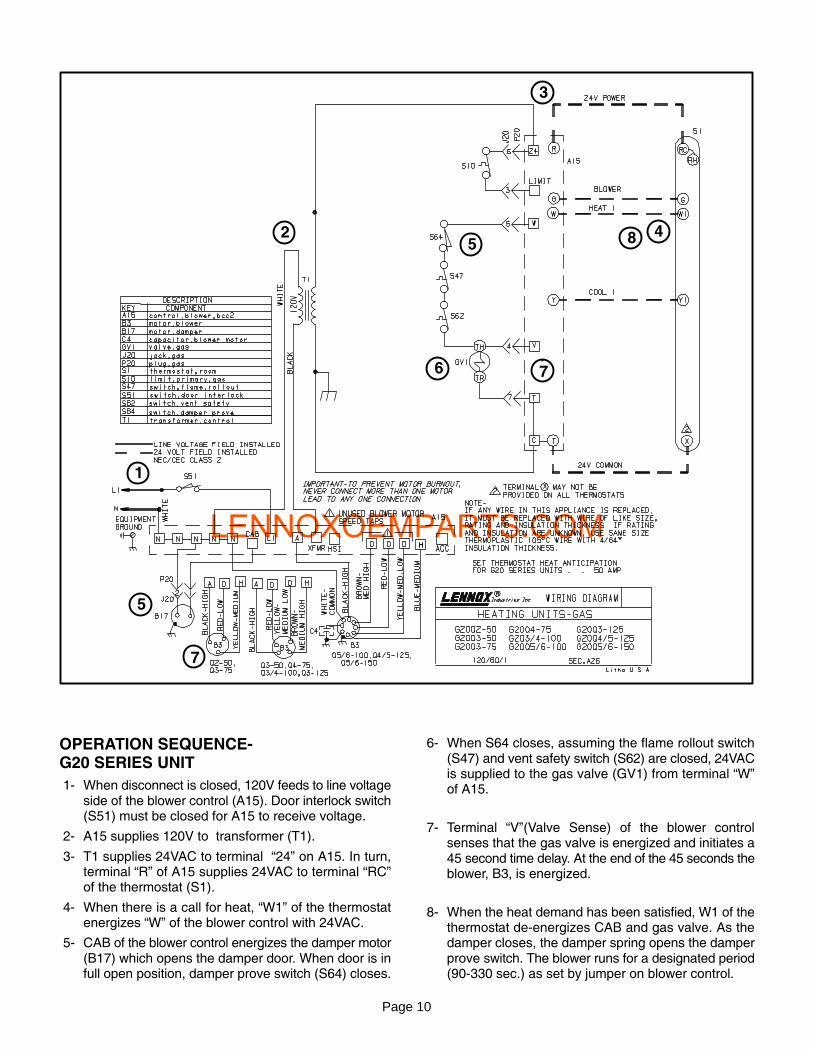
OPERATION SEQUENCE−G20 SERIES UNIT
1− When disconnect is closed, 120V feeds to line voltageside of the blower control (A15). Door interlock switch(S51) must be closed for A15 to receive voltage.
2− A15 supplies 120V to transformer (T1).
3− T1 supplies 24VAC to terminal �24" on A15. In turn,terminal �R" of A15 supplies 24VAC to terminal �RC"of the thermostat (S1).
4− When there is a call for heat, �W1" of the thermostatenergizes �W" of the blower control with 24VAC.
5− CAB of the blower control energizes the damper motor(B17) which opens the damper door. When door is infull open position, damper prove switch (S64) closes.
6− When S64 closes, assuming the flame rollout switch(S47) and vent safety switch (S62) are closed, 24VACis supplied to the gas valve (GV1) from terminal �W"of A15.
7− Terminal �V"(Valve Sense) of the blower controlsenses that the gas valve is energized and initiates a45 second time delay. At the end of the 45 seconds theblower, B3, is energized.
8− When the heat demand has been satisfied, W1 of thethermostat de−energizes CAB and gas valve. As thedamper closes, the damper spring opens the damperprove switch. The blower runs for a designated period(90−330 sec.) as set by jumper on blower control.

LENNOXOEMPARTS.COM
Page 11
2
1
3
4
5
6
7
8
9
10
7
5
9
OPERATION SEQUENCE−G20E SERIES (ELECTRONIC CONTROL)
1− When disconnect is closed, 120V feeds to line voltageside of the blower control (A15). Door interlock switch(S51) must be closed for A15 to receive voltage.
2− A15 supplies 120V to transformer (T1).
3− T1 supplies 24VAC to terminal �24" on A15. In turn,terminal �R" of A15 supplies 24VAC to terminal �RC"of the thermostat (S1).
4− When there is a call for heat, W1 of the thermostat en�ergizes W of the blower control with 24VAC.
5− CAB of the blower control energizes the damper motor(B17) which opens the damper door. When door is infull open position, damper prove switch (S64) closes.
6− When S64 closes, assuming the flame rollout switch(S47) and vent safety switch (S62) are closed, 24VAC
is supplied to the �TH" terminal of the electronic control(A3).
7− Through the electronic control, the pilot valve �P" ofthe gas valve opens. The spark electrode ignites thepilot and the flame sensor senses the pilot.
8− When flame is sensed the main gas valve opens andsupplies the burners with gas.
9− Terminal �V" (Valve Sense) of the blower controlsenses that the gas valve is energized and initiates a45 second time delay. At the end of the 45 seconds theblower, (B3) is energized.
10− When the heat demand has been satisfied, W1 of thethermostat de−energizes the gas valve and damperspring closes the damper door. As the damper doorcloses, the damper prove switch opens. The blowerruns for a designated period (90−330 sec.) as set byjumper on blower control.

LENNOXOEMPARTS.COM
Page 12
CHECK:1−UNIT POWER2−INTERLOCK SWITCH3−TRANSFORMER4−LIMIT SWITCH
START
IS24VAC ACROSS
R & T?
YES
JUMPER ACROSSSCREWS R & G
YES
DOES UNITOPERATE?
NO
NO
ISBLOWER
RUNNING ON HIGHSPEED?
NO IS120VAC ACROSS
N1 & A?
REPLACEBCC
NOYES
YES
CHECK BLOWERWIRING AND
BLOWER
IS120VAC ACROSS
N1 & ACC?
NOREPLACEBCC
YES
JUMPER ACROSS R &W
(REMOVE R & G JUMPER)
ISDAMPER MOTOR
ON?
NO
REPLACEBCC
NO IS120VAC ACROSS
N1 & CAB?
CHECKDAMPER MOTOR
WIRING ANDDAMPER MOTOR
YES
YES AREBURNERS
LIT?
NO
CHECK:1−DAMPER MOTOR2−IGNITION CONTROL3−GAS VALVE4−IGNITOR5−LIMIT SWITCHES6−PROVE SWITCHYES
IS BLOWER RUNNING ON LOW
SPEED, 45 SEC.AFTER FURNACE
LIGHTS?
NOIS
120VAC ACROSSN1 & H?
YES
IS24VAC ACROSS
T & V?
REPLACEBCC
NO
NO
CHECKWIRING
YESIS120VAC ACROSS
N1 & ACC?
YES
REMOVER & W JUMPER
AFTERTHE SELECTEDTIME, DOES THEBLOWER TURN
OFF?
YES NO
YES
REPLACEBCC
END OF TEST
BCCTROUBLESHOOTING
FLOWCHART
NO
REPLACEBCC2−1
CHECK BLOWERWIRING AND
BLOWER
FIGURE 15