corning cable systems - micro cabling systems – the underlying principle our cable conceptfor...
TRANSCRIPT

OEM Data Centers Project Services
Carrier Networks Private Networks
COPYRIGHT© 2001
Corning Cable Systems GmbH & Co. KGP. O. Box 70 03 0981303 MunichTel.: +49-89-51 11-30 86Fax: +49-89-51 11-34 00
www.corning.com/cablesystems/europe
All rights reserved. This document may not be reproduced or duplicated withoutprior written permission from Corning Cable Systems GmbH & Co. KG.
Delivery information and technical specifications may be subject to changewithout notice.Corning Cable Systems GmbH & Co. KG reserves the right to implementimprovements, expansions or other modifications to Corning Cable Systems productswithout prior notice. This may particularly result in changes to specifications andother product information.Claims concerning the supply of a specific product to precise specificationsshall be deemed valid only after a binding order is accepted by Corning CableSystems GmbH & Co. KG.
Printed in Germany.
C1-K
10-3
-760
0 /
CCS
0202
3.
CORNING CABLE SYSTEMS
OEM Data Centers Project Services
Carrier Networks Private Networks
Snak
e.M
icha
el P
.Gio
rdan
o.N
ovem
ber
200
0
Micro Cabling SystemsNew Installation Methods for MCS-Drain, S.L.I.M.,MCS-Liner and MCS-Road Optical Fiber Cables
CorningCable Systems

Micro Cabling Systems 4The Underlying Principle
MCS-Drain 8For Drain Systems
S.L.I.M. 14and Robot Installation

CORNING CABLE SYSTEMS
MCS-Liner 18For Drain and Pipeline Repair
MCS-Road 20For Roads

> Micro Cabling Systems – The Underlying Principle
Our cable concept for sewer systems comprisesthree products:MCS-Drain for installation in drain and sewer systems.S.L.I.M. for installation by robot.And MCS-Liner for drain system renewal and repair.
4
Our cable concept for the road: MCS-Road.Its fast, simple installation keeps roadsobstacle-free and traffic flowing freely.
MCS-Road MCS-Drain
Installing optical fiber cables using conventionalmethods is a long, costly and nerve-wracking pro-cess. Now Corning has developed a revolutionaryalternative for installation wherever extensive exca-vation would disrupt traffic, generate enormouscosts and be time-consuming: Micro CablingSystems (MCS ®) and S.L.I.M.
This new optical fiber system enables installation tobe completed rapidly and at reasonable costs. Insidewalks, roads or subterranean drain systems.Whether installing new local networks, the expan-sion of existing networks or campus cabling of in-dustrial sites (such as backbone cabling) – we alwayshave the ideal solution.
Our cabling concept for roads: MCS-Road. Whereconventional methods require excavations of 60 –80 cm depth, these special MCS optical fiber cablesare laid in a shallow 8 – 10 cm groove in the street orsidewalk.
MCS-Drain is the answer when cabling needs to beinstalled directly in drain or sewer systems.Installation can be completed using standard equip-ment and machinery, eliminating all excavationcosts. A further option for cable installation in drainand sewer systems is S.L.I.M., a robot-assisted cableinstallation method in which the robot positions thecable in the upper area of the drainage channel,bores attachment holes for special dowels and fixesthe cable in position using elastomeric clips. Boththese options drastically reduce the time and com-plexity of installation.
And we've simplified the new optical fiber systemstill further by designing both concepts - MCS Roadand MCS-Drain – fully compatible with each otherand with conventional optical fiber networks.Sounds simple? It is.
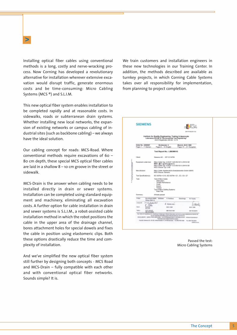
Passed the test:Micro Cabling Systems
>
5The Concept
We train customers and installation engineers inthese new technologies in our Training Center. Inaddition, the methods described are available asturnkey projects, in which Corning Cable Systemstakes over all responsibility for implementation,from planning to project completion.
> The Best Grounds
6
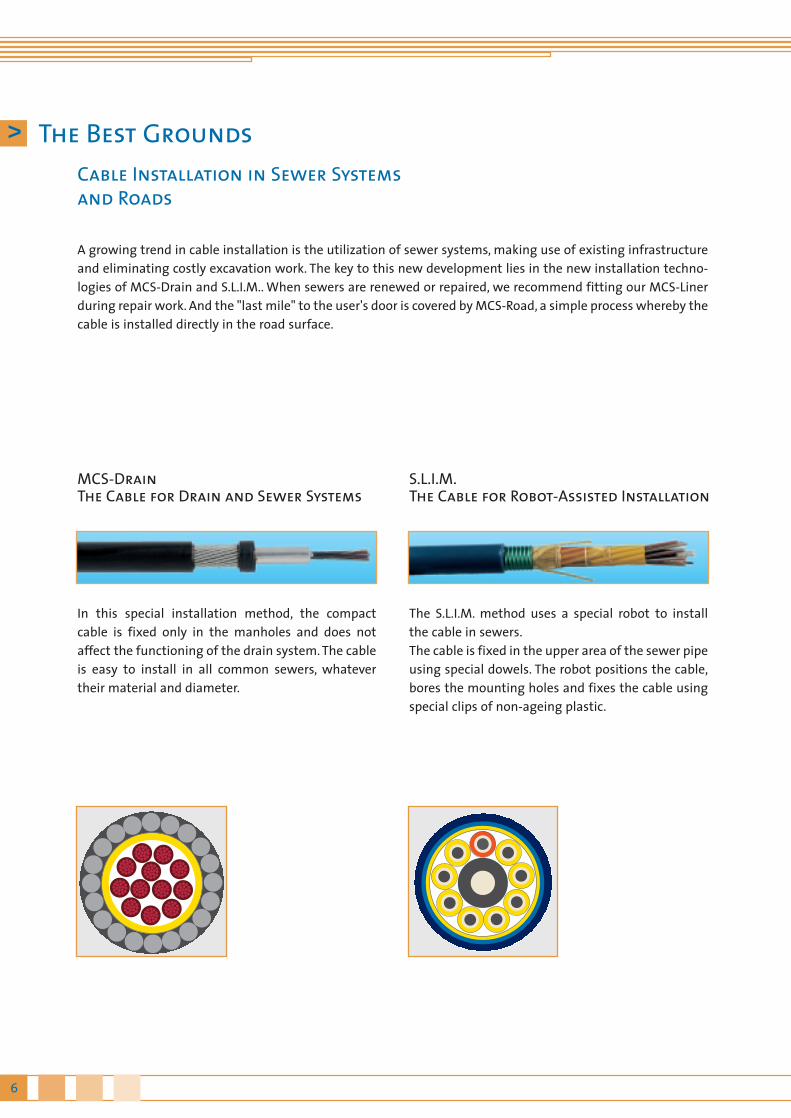
MCS-DrainThe Cable for Drain and Sewer Systems
In this special installation method, the compactcable is fixed only in the manholes and does notaffect the functioning of the drain system. The cableis easy to install in all common sewers, whatevertheir material and diameter.
The S.L.I.M. method uses a special robot to installthe cable in sewers.The cable is fixed in the upper area of the sewer pipeusing special dowels. The robot positions the cable,bores the mounting holes and fixes the cable usingspecial clips of non-ageing plastic.
S.L.I.M.The Cable for Robot-Assisted Installation
Cable Installation in Sewer Systemsand Roads
A growing trend in cable installation is the utilization of sewer systems, making use of existing infrastructureand eliminating costly excavation work. The key to this new development lies in the new installation techno-logies of MCS-Drain and S.L.I.M.. When sewers are renewed or repaired, we recommend fitting our MCS-Linerduring repair work. And the "last mile" to the user's door is covered by MCS-Road, a simple process whereby thecable is installed directly in the road surface.
7The Concept
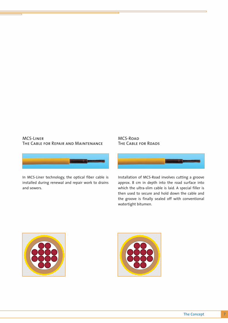
In MCS-Liner technology, the optical fiber cable isinstalled during renewal and repair work to drainsand sewers.
Installation of MCS-Road involves cutting a grooveapprox. 8 cm in depth into the road surface intowhich the ultra-slim cable is laid. A special filler isthen used to secure and hold down the cable andthe groove is finally sealed off with conventionalwatertight bitumen.
MCS-RoadThe Cable for Roads
MCS-LinerThe Cable for Repair and Maintenance

8
MCS-Drain is suitable for deployment in all existing drain channel systems, such as sewers, storm and mixeddrainage systems. The MCS-Drain is pulled into place and then tensioned, so that on completion of theinstallation it is located in the upper curvature of the drain pipe.The special feature of this installation method is that the compact cable is clamped solely in the manholesand does not affect the functioning of the drain system. The cable is easy to install in all common sewers,whatever their material and up to a diameter of 180 mm.
Use
The MCS-Drain cable has a diameter of just under 12mm and was designed specifically for installation indrain channels. The cable is of proven high quality,contains up to 144 fibers and is of high tensilestrength.
Benefits
• Simple, rapid installation (up to 0,5 km/day)• No mechanical boring holes in drain pipes• Low installation and fitting costs• No special equipment needed
> Fundamental Information –MCS-Drain in Drain and Sewer Systems

> Installation of MCS-Drain
9MCS-Drain
First, curved cable guides and attachments for thepulling eye are fitted in the manholes. A standardcleaning vehicle is used to clean the drain pipe andsimultaneously pulls through the MCS-Drain cable.The tension helixes are attached to the cable anddrawn through the pulling eye, and the cable is ten-sioned.
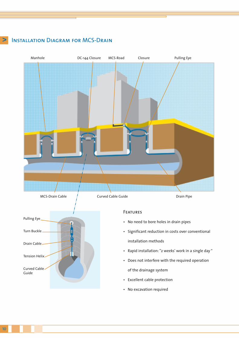
Manhole DC-144 Closure MCS-Road Pulling EyeClosure
Drain PipeMCS-Drain Cable Curved Cable Guide
Features
• No need to bore holes in drain pipes
• Significant reduction in costs over conventional
installation methods
• Rapid installation: "2 weeks' work in a single day “
• Does not interfere with the required operation
of the drainage system
• Excellent cable protection
• No excavation required
Pulling Eye
Turn Buckle
Drain Cable
Tension Helix
Curved CableGuide
10
> Installation Diagram for MCS-Drain

> MCS-Drain: Fittings
11MCS-Drain
Use
The DC-144 closure is suitable for use as an imper-meable closure against pressurized water in branchesand pipe junctions. The cables are led in and ten-sioned at the connection pipes. This sturdy, corro-sion-resistant closure is impermeable to pressurizedwater and can be mounted in both manholes androad surfaces.
Features
• Installation of cut MCS-Drain cables(mid-span access)
• Short mounting times• Replaceable adapters enable a variety of cable
types to be used (Drain,Road,S.L.I.M.,Standard)• Reusable sealant enables closure to be re-opened
and closed • Splices are protected by Tekni-Tubes, enabling
optical fiber length to be varied
Make-up
• Stainless steel armor, permanently elastic sealant• Fibers grouped within a single tube• 4 cable lead-ins
Closure DC-144, open
> DC-144 Closure

> Order Information for MCS-Drain
12
The standard MCS-Drain Cable comprises single-mode fibers **) in compliance with ITU-T Rec.G.652;with the following optical values:
Wavelength range approx. 1310 nmAttenuationDispersion
Wavelength range 1550 nmAttenuationDispersion
Cable Make-up
The MCS-Drain comprises a maxi-tube with water-tight filler. The tube has an approx. 6 mm externaldiameter, is longitudinally watertight and contains12 to 144 fibers. The maxi-tube has steel wire armo-ring to absorb tensile forces and protect againstrodents, and has an outer sheath of robust polyethy-lene. This compact cable has high tensile strengthand is rodent-proof.
Coding
Fibers are color-coded in groups of 12 with coloredbinders, enabling binders and optical fibers to beclearly identified.
Mechanical Specifications
External diameter Weight
approx. 11 mmapprox. 225 kg/km
Installation and Operation Information
Minimum bending radius Max. permissible tensile force
100 mm 15 kN
Temperature Ranges
Operation Installation and fitting Transport and storage
–30° to +70°C–15° to +70°C–35° to +80°C
Optical Specifications
0,36 dB/km*)3,5 ps/(nm x km)*)
0,25 dB/km*)18 ps/(nm x km)*)
*) Other values on request**) Multimode and LEAF® fibers on request
> MCS-Drain: Technical Specifications
Cable order code
A-DAB 2Y 1x144 144 V 46904-D144-U75
Number of fibers Order number
150 mm
Drain pipe diameter

13MCS-Drain and S.L.I.M.
> Underground Information –S.L.I.M. and Robot Installation
Use
• Mounted by robot in sewer systems • Installation in man-sized drain systems • For high mechanical stress levels• For areas at high risk from rodents• Direct underground installation• Installation in concrete channels• High number of fibers
Features
• Single-layer stranded make-up (up to 216 fibers)• Corrugated steel sheath protects against rodents
and mechanical strain• Slim, sturdy cable
Benefits
• Designed for installation by robot anywherewithin the drain pipe
• Compact make-up, high number of fibers• Special dowels enable 2 parallel cables to be
fixed in drain channel

14
> Canister Closure
> S.L.I.M. Fittings
This flat closure can be fitted to the wall of a man-hole.The stainless steel casing is impermeable to pressu-rized water, explosion-proof and ultra-rugged.Splices are in individual containers, enabling indivi-dual fibers to be handled without disruption to theoverall service. Closure capacity can be expanded atany time by fitting a different cover model.

15MCS-S.L.I.M.
> Order Information for S.L.I.M.
> S.L.I.M. Technical Specifications
Cable Make-up
The S.L.I.M. cable contains up to 216 fibers, with 24fibers per bunch core grouped around the centralelement.
Coding
Bar and color coding are used for identification.
Temperature Range
Operation Installation and Fitting Transport and Storage
–25° to +60°C– 5° to +50°C–25° to + 70°C
Test Procedures
Subjected to tests in compliance with IEC 60793-1,60794-2 and VDE 0888 Section 3
• Tensile strength• Impact resistance• Lateral crush resistance • Bending• Response to temperature• Longitudinal watertightness
Cable order code
A-D (SF) ZN 8 R 2Y 9x24 216 C 1110190/824
Number of fibers Order number
200 mm
Drain pipe diameter
> Order Information for MCS-Liner
16
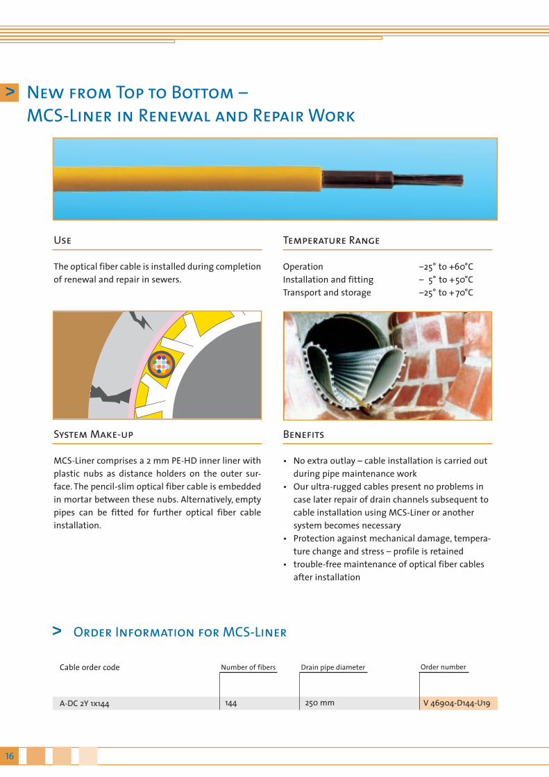
> New from Top to Bottom –MCS-Liner in Renewal and Repair Work
Use
The optical fiber cable is installed during completionof renewal and repair in sewers.
System Make-up
MCS-Liner comprises a 2 mm PE-HD inner liner withplastic nubs as distance holders on the outer sur-face. The pencil-slim optical fiber cable is embeddedin mortar between these nubs. Alternatively, emptypipes can be fitted for further optical fiber cableinstallation.
Temperature Range
OperationInstallation and fitting Transport and storage
Benefits
• No extra outlay – cable installation is carried outduring pipe maintenance work
• Our ultra-rugged cables present no problems incase later repair of drain channels subsequent tocable installation using MCS-Liner or anothersystem becomes necessary
• Protection against mechanical damage, tempera-ture change and stress – profile is retained
• trouble-free maintenance of optical fiber cablesafter installation
–25° to +60°C– 5° to +50°C–25° to + 70°C
Cable order code
A-DC 2Y 1x144 144 V 46904-D144-U19
Number of fibers Order number
250 mm
Drain pipe diameter

17MCS-Liner
Defective sewage pipes are repaired with MCS-Linerand the cables installed simultaneously. The pencil-slim cable is embedded in the annular gap betweenthe two PE-HD sheath liners.The nubs on the liner determine the gap size. Thecable and liner are drawn into the defective pipetogether and the annular gap subsequently filledwith special mortar giving a static load-bearingcomposite system with high resistance to extremesof temperature and to aggressive substances.
> Installation Diagram for MCS-Liners
18
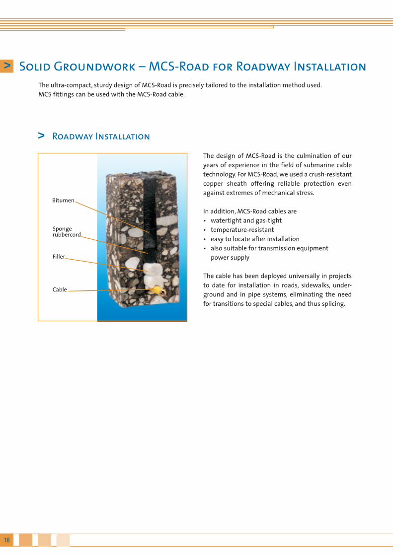
> Roadway Installation
The design of MCS-Road is the culmination of ouryears of experience in the field of submarine cabletechnology. For MCS-Road, we used a crush-resistantcopper sheath offering reliable protection evenagainst extremes of mechanical stress.
In addition, MCS-Road cables are• watertight and gas-tight• temperature-resistant• easy to locate after installation• also suitable for transmission equipment
power supply
The cable has been deployed universally in projectsto date for installation in roads, sidewalks, under-ground and in pipe systems, eliminating the needfor transitions to special cables, and thus splicing.
> Solid Groundwork – MCS-Road for Roadway InstallationThe ultra-compact, sturdy design of MCS-Road is precisely tailored to the installation method used.MCS fittings can be used with the MCS-Road cable.
Cable
Spongerubbercord
Filler
Bitumen
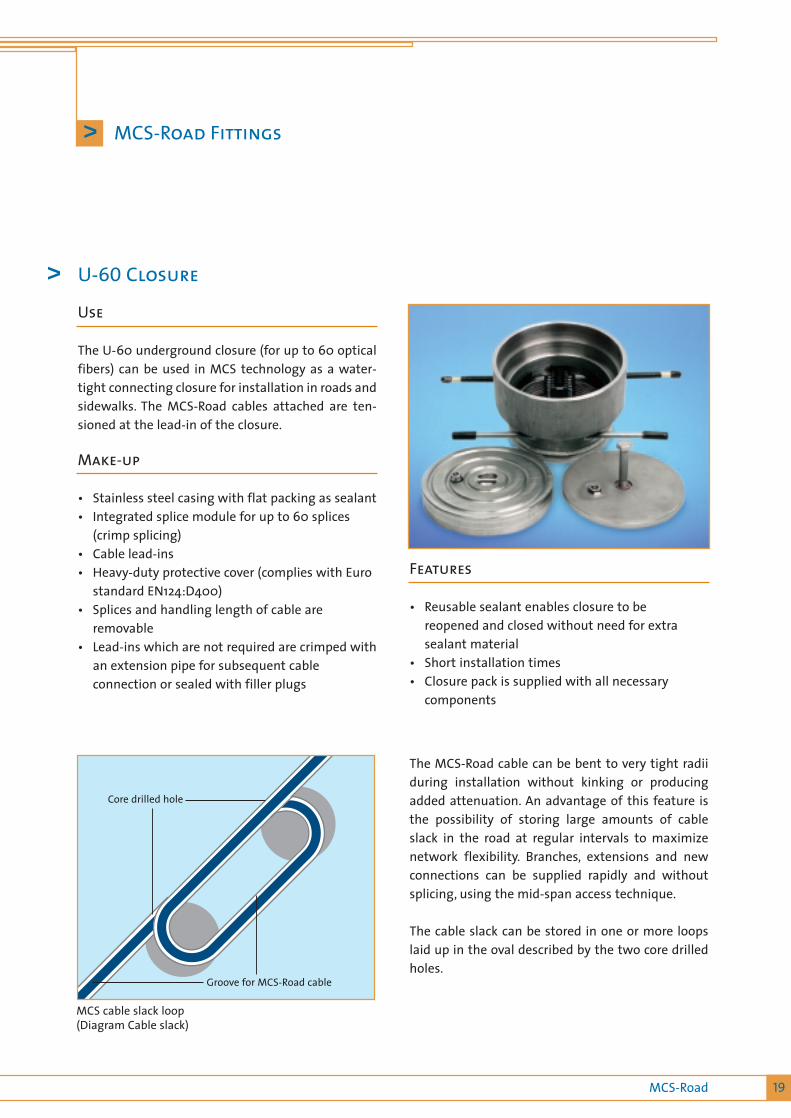
Core drilled hole
Groove for MCS-Road cable
19MCS-Road
> MCS-Road Fittings
MCS cable slack loop(Diagram Cable slack)
The MCS-Road cable can be bent to very tight radiiduring installation without kinking or producingadded attenuation. An advantage of this feature isthe possibility of storing large amounts of cableslack in the road at regular intervals to maximizenetwork flexibility. Branches, extensions and newconnections can be supplied rapidly and withoutsplicing, using the mid-span access technique.
The cable slack can be stored in one or more loopslaid up in the oval described by the two core drilledholes.
Features
• Reusable sealant enables closure to bereopened and closed without need for extrasealant material
• Short installation times • Closure pack is supplied with all necessary
components
Use
The U-60 underground closure (for up to 60 opticalfibers) can be used in MCS technology as a water-tight connecting closure for installation in roads andsidewalks. The MCS-Road cables attached are ten-sioned at the lead-in of the closure.
Make-up
• Stainless steel casing with flat packing as sealant• Integrated splice module for up to 60 splices
(crimp splicing)• Cable lead-ins• Heavy-duty protective cover (complies with Euro
standard EN124:D400)• Splices and handling length of cable are
removable• Lead-ins which are not required are crimped with
an extension pipe for subsequent cableconnection or sealed with filler plugs
> U-60 Closure
20
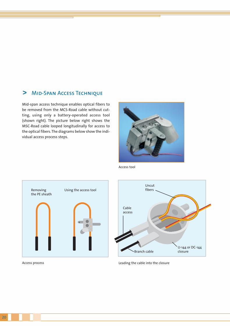
Mid-span access technique enables optical fibers tobe removed from the MCS-Road cable without cut-ting, using only a battery-operated access tool(shown right). The picture below right shows theMSC-Road cable looped longitudinally for access tothe optical fibers. The diagrams below show the indi-vidual access process steps.
Access tool
Access process Leading the cable into the closure
Uncutfibers
Cableaccess
Branch cableU-144 or DC-144closure
Using the access tool Removingthe PE sheath
> Mid-Span Access Technique

21MCS-Road
> Order Information for MCS-Road
The MCS-Road Cable contains standard single-modefibers **) complying with ITU-T Rec.G.652 and withthe following optical specifications:
Wavelength range 1310 nmAttenuationDispersion
Wavelength range 1550 nmAttenuationDispersion
Cable Make-up
The MCS-Road cable comprises a longitudinallywatertight filled copper tube of around 5 mm exter-nal diameter, containing 12 –144 optical fibers *). Thecopper tube is insulated with a polyethylene sheath.The overall cable has a maximum external diameterof 9.6 mm. The compact MCS-Road cable is crush-resistant and corrosion-resistant, rugged and easilybent without kinking.*) Higher numbers of fibers on request
Coding
The optical fibers are individually color-coded. Incables with more than twelve optical fibers, fibersare bunched into groups of 12 with colored binders,so that individual fibers can be clearly identified.
Mechanical Data
External diameter Weight
approx. 9.6 mmapprox. 154 kg/km
Installation and Operation Information
Minimum bending radius Max. permissible tensile force
70 mm 1.000 N
Temperature Range
OperationInstallation and Fitting Transport and Storage
–30° to +70°C5° to +70°C
–35° to +80°C
Optical Data
0,36 dB/km*)3,5 ps/(nm x km)*)
0,25 dB/km*)18 ps/(nm x km)*)
*) Other values on request**) Multimode and LEAF® fibers on request
> MCS-Road Technical Specifications
Cable order code
A-DC 2Y 1x144 144 V 46904-D144-U19
Number of fibers Order number

22
> Getting to the Bottom of Things
Convinced? Now you've had a chance toget to know Micro Cabling Systems andfind out about their applications and theirextensive range of features and benefits.You've compared our different cablemodels, and discovered what makes themspecial. Not enough? Need more? Morefeatures, more information, more details?Good - that's just what we hoped to hearfrom you. We've put together a selectionof our product catalogues, available free ofcharge upon request. Of course, you'realso welcome to get in touch with usdirectly, by calling our Customer Servicestaff on +44-1483-526697. We'll be happyto answer all your questions, down to thelast detail.Our Training Center offers courses in allinstallation techniques, with successfulparticipants being certified as qualifiedcable installation engineers.
> Overview of Topics
23Overview
C1-K19-2-7600
C1-W11-1-7600
C1-B12-1-7600 C1-B5-2-7600
C1-B4-2-7600
C1-P70-1-7600 C1-B9-1-7600