cordless terminal mobility (ctm); feature package 1 … · feature package 1 (fp1); ctm circuit ......
TRANSCRIPT

Draft EN 302 096 V0.2.2 (1999-03)European Standard (Telecommunications series)
Digital Enhanced Cordless Telecommunications (DECT);Cordless Terminal Mobility (CTM);
Feature Package 1 (FP1);CTM circuit-switched data profile, 32 kbit/s and 64 kbit/s
Unrestricted Digital Information (UDI)

ETSI
Draft EN 302 096 V0.2.2 (1999-03)2
ReferenceDEN/DECT-030127 (jeo000pc.PDF)
KeywordsDECT, CTM, mobility, network
ETSI
Postal addressF-06921 Sophia Antipolis Cedex - FRANCE
Office address650 Route des Lucioles - Sophia Antipolis
Valbonne - FRANCETel.: +33 4 92 94 42 00 Fax: +33 4 93 65 47 16
Siret N° 348 623 562 00017 - NAF 742 CAssociation à but non lucratif enregistrée à laSous-Préfecture de Grasse (06) N° 7803/88
Individual copies of this ETSI deliverablecan be downloaded from
http://www.etsi.orgIf you find errors in the present document, send your
comment to: [email protected]
Copyright Notification
No part may be reproduced except as authorized by written permission.The copyright and the foregoing restriction extend to reproduction in all media.
© European Telecommunications Standards Institute 1999.All rights reserved.

ETSI
Draft EN 302 096 V0.2.2 (1999-03)3
Contents
Intellectual Property Rights................................................................................................................................5
Foreword ............................................................................................................................................................5
1 Scope........................................................................................................................................................6
2 References................................................................................................................................................6
3 Definitions and abbreviations ..................................................................................................................73.1 Definitions ......................................................................................................................................................... 73.2 Abbreviations..................................................................................................................................................... 9
4 Description of services...........................................................................................................................104.1 Reference configuration................................................................................................................................... 104.2 Service objectives ............................................................................................................................................ 114.2.1 General ....................................................................................................................................................... 11
5 NWK layer requirements .......................................................................................................................115.1 General............................................................................................................................................................. 115.2 Requirements ................................................................................................................................................... 12
6 DLC layer requirements.........................................................................................................................126.1 C-plane requirements ....................................................................................................................................... 126.2 U-plane requirements....................................................................................................................................... 12
7 MAC layer requirements........................................................................................................................12
8 PHL layer requirements .........................................................................................................................12
9 Management requirements.....................................................................................................................12
Annex A (normative): Aspects of V.120 for use with CTM FP1 .....................................................13
A.1 Terminal adaptation sublayer.................................................................................................................13A.1.1 Mode of operation............................................................................................................................................ 13A.1.2 Logical links .................................................................................................................................................... 13A.1.3 Parameter negotiation ...................................................................................................................................... 14A.1.4 Bearer service .................................................................................................................................................. 14A.1.5 Terminal adoption header ................................................................................................................................ 14A.1.6 Mode of transmission....................................................................................................................................... 14
A.2 Data Link control and core sublayer ......................................................................................................14A.2.1 Signalling protocols ......................................................................................................................................... 14A.2.2 System parameters ........................................................................................................................................... 15
A.3 Physical sublayer....................................................................................................................................15
Annex B (normative): Interworking ..................................................................................................16
B.1 Interworking to connection-oriented bearer services.............................................................................16B.1.1 Scope ............................................................................................................................................................... 16B.1.2 Reference configuration................................................................................................................................... 16B.1.3 Interworking service of DTE using V.24 connection....................................................................................... 17B.1.3.1 General ....................................................................................................................................................... 17B.1.3.2 TAF interworking to ITU-T Recommendation V.24.................................................................................. 17B.1.3.2.1 General ................................................................................................................................................. 17B.1.3.2.2 V.24 Interchange circuit handling rules................................................................................................ 17B.1.3.2.3 Call establishment signalling handling ................................................................................................. 18B.1.3.3 DECT FP Interworking procedures............................................................................................................ 18B.1.3.3.1 General ................................................................................................................................................. 18B.1.3.3.2 Call establishment signalling handling ................................................................................................. 19

ETSI
Draft EN 302 096 V0.2.2 (1999-03)4
B.1.3.3.3 Modem selection................................................................................................................................... 19
B.2 <<IWU-ATTRIBUTES>> coding .........................................................................................................23
Bibliography.....................................................................................................................................................27
History..............................................................................................................................................................28

ETSI
Draft EN 302 096 V0.2.2 (1999-03)5
Intellectual Property RightsIPRs essential or potentially essential to the present document may have been declared to ETSI. The informationpertaining to these essential IPRs, if any, is publicly available for ETSI members and non-members, and can be foundin SR 000 314: "Intellectual Property Rights (IPRs); Essential, or potentially Essential, IPRs notified to ETSI in respectof ETSI standards", which is available free of charge from the ETSI Secretariat. Latest updates are available on theETSI Web server (http://www.etsi.org/ipr).
Pursuant to the ETSI IPR Policy, no investigation, including IPR searches, has been carried out by ETSI. No guaranteecan be given as to the existence of other IPRs not referenced in SR 000 314 (or the updates on the ETSI Web server)which are, or may be, or may become, essential to the present document.
ForewordThis European Standard (Telecommunications series) has been produced by ETSI Project Digital Enhanced CordlessTelecommunications (DECT), and is now submitted for the Public Enquiry phase of the ETSI Two-step ApprovalProcedure.
The present document is based on ETS 300 175-1 to 8 [1] to [8] and ETS 300 824 [10]. General attachmentrequirements are based on TBR 6 [19] and, where applicable, voice attachment requirements are based on TBR 10 [20].
The present document has been developed in accordance to the rules of documenting a profile specification as describedin ISO/IEC 9646-6 [11].
Proposed national transposition dates
Date of latest announcement of this EN (doa): 3 months after ETSI publication
Date of latest publication of new National Standardor endorsement of this EN (dop/e): 6 months after doa
Date of withdrawal of any conflicting National Standard (dow): 6 months after doa

ETSI
Draft EN 302 096 V0.2.2 (1999-03)6
1 ScopeThe present document specifies that set of technical requirements for Digital Enhanced Cordless Telecommunications(DECT) Fixed Part (FP) and DECT Portable Part (PP) necessary for the support of the Cordless Terminal Mobility(CTM) Feature Package 1 (CTM-FP1).
The objective of the present document is to ensure the Air Interface (AI) interoperability of DECT CTM-FP1 PPs andDECT CTM-FP1 FPs if applied.
The CTM service allows users of cordless terminals to be mobile within and between networks. Where radio coverage isprovided and the cordless terminal has appropriate access rights the user shall be able to make calls from, and to receivecalls at, any location within the fixed public and/or private networks, and may move without interruption of a call inprogress.
CTM-FP1 defines 32Kbit/sec Circuit Switched Data services (CSD) for CTM users.
The present document is intended as an extension of the DECT CTM Access Profile (ETS 300 824 [10]) mobilityfeatures mandatory base covering the requirements for CTM-FP1.
2 ReferencesThe following documents contain provisions which, through reference in this text, constitute provisions of the presentdocument.
• References are either specific (identified by date of publication, edition number, version number, etc.) ornon-specific.
• For a specific reference, subsequent revisions do not apply.
• For a non-specific reference, the latest version applies.
• A non-specific reference to an ETS shall also be taken to refer to later versions published as an EN with the samenumber.
[1] ETS 300 175-1: "Digital Enhanced Cordless Telecommunications (DECT); Common Interface(CI); Part 1: Overview".
[2] ETS 300 175-2: "Digital Enhanced Cordless Telecommunications (DECT); Common Interface(CI); Part 2: Physical layer (PHL)".
[3] ETS 300 175-3: "Digital Enhanced Cordless Telecommunications (DECT); Common Interface(CI); Part 3: Medium Access Control (MAC) layer".
[4] ETS 300 175-4: "Digital Enhanced Cordless Telecommunications (DECT); Common Interface(CI); Part 4: Data Link Control (DLC) layer".
[5] ETS 300 175-5: "Digital Enhanced Cordless Telecommunications (DECT); Common Interface(CI); Part 5: Network (NWK) layer".
[6] ETS 300 175-6: "Digital Enhanced Cordless Telecommunications (DECT); Common Interface(CI); Part 6: Identities and addressing".
[7] ETS 300 175-7: "Digital Enhanced Cordless Telecommunications (DECT); Common Interface(CI); Part 7: Security features".
[8] ETS 300 175-8: "Digital Enhanced Cordless Telecommunications (DECT); Common Interface(CI); Part 8: Speech coding and transmission".
[9] EN 300 444 (V1.2): "Digital Enhanced Cordless Telecommunications (DECT); Generic AccessProfile (GAP)".

ETSI
Draft EN 302 096 V0.2.2 (1999-03)7
[10] ETS 300 824: "Digital Enhanced Cordless Telecommunications (DECT); Cordless TerminalMobility (CTM); CTM Access Profile (CAP)".
[11] ISO/IEC 9646-6: "Information technology - Open Systems Interconnection - Conformance testingmethodology and framework - Part 6: Protocol profile test specification".
[12] CCITT Recommendation Q.922: "ISDN data link layer specification for frame mode bearerservices".
[13] ITU-T Recommendation Q.931: "Digital Subscriber Signalling System No. 1 (DSS 1) - ISDN user-network interface layer 3 specification for basic call control".
[14] ITU-T Recommendation Q.933: "Integrated services digital network (ISDN) digital subscribersignalling system no. 1 (DSS 1) - signalling specifications for frame mode switched and permanentvirtual connection control and status monitoring".
[15] ITU-T Recommendation V.24: "List of definitions for interchange circuits between data terminalequipment (DTE) and data circuit-terminating equipment (DCE)".
[16] ITU-T Recommendation V.42bis: "Data compression procedures for data circuit terminatingequipment (DCE) using error correction procedures".
[17] ITU-T Recommendation V.110: "Support by an ISDN of data terminal equipments with V-Seriestype interfaces".
[18] ITU-T Recommendation V.120: "Support by an ISDN of data terminal equipment with V-Seriestype interfaces with provision for statistical multiplexing".
[19] TBR 6: "Digital Enhanced Cordless Telecommunications (DECT); General terminal attachmentrequirements".
[20] TBR 10: "Digital Enhanced Cordless Telecommunications (DECT); General terminal attachmentrequirements; Telephony applications".
3 Definitions and abbreviations
3.1 DefinitionsFor the purposes of the present document, the following definitions apply:
authentication: the process whereby a DECT subscriber is positively verified to be a legitimate user of a particular FP.
NOTE 1: Authentication is generally performed at call set-up, but may also be done at any other time (e.g. during acall).
bearer service: a type of telecommunication service that provides a defined capability for the transmission of signalsbetween user-network interfaces.
NOTE 2: The DECT user-network interface corresponds to the top of the Network (NWK) layer (layer 3).
C-plane: the control plane of the DECT protocol stacks, which contains all of the internal DECT protocol control, butmay also include some external user information.
NOTE 3: The C-plane stack always contains protocol entities up to and including the NWK layer.
call: all of the NWK layer processes involved in one NWK layer peer-to-peer association.
NOTE 4: Call may sometimes be used to refer to processes of all layers, since lower layer processes are implicitlyrequired.

ETSI
Draft EN 302 096 V0.2.2 (1999-03)8
DECT network: a network that uses the DECT AI to interconnect a local network to one or more portable applications.The logical boundaries of the DECT network are defined to be at the top of the DECT NWK layer.
NOTE 5: A DECT network is a logical grouping that contains one or more FTs plus their associated PT. Theboundaries of the DECT network are not physical boundaries.
Fixed Part (DECT Fixed Part) (FP): a physical grouping that contains all of the elements in the DECT networkbetween the local network and the DECT AI.
NOTE 6: A DECT FP contains the logical elements of at least one FT, plus additional implementation specificelements.
Fixed radio Termination (FT): a logical group of functions that contains all of the DECT processes and procedures onthe fixed side of the DECT AI.
NOTE 7: A FT only includes elements that are defined in the DECT Common Interface (CI) standard. This includesradio transmission elements together with a selection of layer 2 and layer 3 elements.
global network: a telecommunication network capable of offering a long distance telecommunication service.
NOTE 8: The term does not include legal or regulatory aspects, nor does it indicate if the network is a public or aprivate network.
handover: the process of switching a call in progress from one physical channel to another physical channel.
NOTE 9: There are two physical forms of handover, intra-cell handover and inter-cell handover.
incoming call: a call received at a PP.
inter-operability: the capability of FPs and PPs, that enable a PP to obtain access to teleservices in more than oneLocation Area (LA) and/or from more than one operator (more than one service provider).
inter-operator roaming: roaming between FP coverage areas of different operators (different service providers).
Interworking Unit (IWU): a unit that is used to interconnect sub networks.
NOTE 10:The IWU will contain the interworking functions necessary to support the required sub–networkinterworking.
isochronous: pertaining to a signal or a time-varying phenomenon characterized by significant instants separated bytime intervals having a duration theoretically equal to the duration of a unit interval or to an integral multiple of thisduration.
Local Network (LNW): a telecommunication network capable of offering local telecommunication services.
NOTE 11:The term does not include legal or regulatory aspects, nor does it indicate if the network is a publicnetwork or a private network.
MAC connection (connection): an association between one source MAC Multiple Bearer Control (MBC) entity andone destination MAC MBC entity. This provides a set of related MAC services (a set of logical channels), and it caninvolve one or more underlying MAC bearers.
outgoing call: a call originating from a PP.
Portable Application (PA): a logical grouping that contains all the elements that lie beyond the DECT networkboundary on the portable side.
NOTE 12:The functions contained in the PA may be physically distributed, but any such distribution is invisible tothe DECT network.
Portable Part (DECT Portable Part) (PP): a physical grouping that contains all elements between the user and theDECT AI. PP is a generic term that may describe one or several physical pieces.
NOTE 13:A DECT PP is logically divided into one PT plus one or more PAs.
ETSI
Draft EN 302 096 V0.2.2 (1999-03)9
Portable radio Termination (PT): a logical group of functions that contains all of the DECT processes and procedureson the portable side of the DECT AI.
NOTE 14:A PT only includes elements that are defined in the DECT CI standard. This includes radio transmissionelements (layer 1) together with a selection of layer 2 and layer 3 elements.
Radio Fixed Part (RFP): one physical sub-group of a FP that contains all the radio end points (one or more) that areconnected to a single system of antennas.
synchronous: the essential characteristics of time-scales or signals such that their corresponding significant instantsoccur at precisely the same average rate.
synchronous transmission: transmission using isochronous signals in which the sending and receiving instruments areoperating continuously in a constant time difference between corresponding significant instants.
3.2 AbbreviationsFor the purposes of the present document, the following abbreviations apply:
AAL ATM Adaptation LayerAI Air InterfaceATM Asynchronous Transfer ModeCAP CTM Access ProfileCC Call ControlCI Common InterfaceCSD Circuit Switched DataCTM Cordless Terminal MobilityCTM-FP1 Cordless Terminal Mobility Feature Package 1DCE Data Communication EquipmentDECT Digital Enhanced Cordless TelecommunicationsDLC Data Link ControlDTE Data Terminal EquipmentFP Fixed PartFT Fixed radio TerminationGAP Generic Access ProfileGSM Global System for Mobile communicationISDN Integrated Services Digital NetworkIWF Interworking FunctionsIWU Interworking UnitIWF Interworking FunctionLCE Link Control EntityLNW Local NetworkMAC Medium Access ControlMBC Multiple Bearer ControlMM Mobility ManagementNWK NetworkPA Portable ApplicationPHL Physical layerPP Portable PartPT Portable radio TerminationRFP Radio Fixed PartSAP Service Access PointTAF Terminal Adoption Functions

ETSI
Draft EN 302 096 V0.2.2 (1999-03)10
4 Description of services
4.1 Reference configurationThe reference configuration for this profile shall be as shown in figure 1.
PHY
MAC
DLC
NWK
PHY
MAC
DLCNWK
Circuitorientednetworkcontrol
IWF
PP FP
Application
NetworkControl
Network
Application
Serviceinterworkingmanagement
C-Plane
PHY
MAC
LU1
V.120
PHY
MAC
LU1V.120
Network
IWF
PP FP
Application
Network
Application
NetworkControlofferingcircuit
switchedbearer
services
U-Plane
Figure 1: Profile reference configuration showing interworkingto connection-oriented networks via the C-plane and U-plane

ETSI
Draft EN 302 096 V0.2.2 (1999-03)11
4.2 Service objectives
4.2.1 General
The service objectives for the C-plane are those of CTM feature package 1 as described in the CTM FP1 ServiceDescription.
The service objectives for the U-plane are listed in subclauses 4.2.2.
The U-plane service objective for the 32 kbit/s service are detailed in table 1:
Table 1: Service objectives of the 32 kbit/s service
Transfer mode Circuit modeTransfer capability Unrestricted digital
Data structure integrity octetContinuous data rate by steps of 2,4 kbit/s
up to 28,8 kbit/s; andby steps of 4 kbit/s up to
28,0 kbit/sUser data protection optional
Service change and negotiation optionalEncryption support Mandatory
User data compression Optional (note 1)
NOTE: User data compression may be used only if user data are protected. Data compression shall be achievedaccording to ITU-T Recommendation V.42bis [16].
5 NWK layer requirements
5.1 GeneralThe NWK layer provisions shall include the following entities:
- Call Control (CC);
- Link Control Entity (LCE);
- Mobility Management (MM).
Portable Part and Fixed Part CC entities shall use circuit switched mode procedures.
Annex B specifies how procedures shall be used.
The MM requirements shall be aligned to the requirements of the CAP, defined in ETS 300 824 [10].
The provisions of NWK layer, ETS 300 175-5 [5] shall be implemented with respect to the services, procedures,messages and information elements coding listed in annex B. The provisions of ETS 300 175-6 [6] shall be implementedwith respect to the structure and use of identities.
Support for exchanged attribute procedures shall be mandatory (ETS 300 175-5 [5], subclause 15.2.3).
The <<RELEASE-REASON>> element shall always be included in the {CC-RELEASE-COM} message.

ETSI
Draft EN 302 096 V0.2.2 (1999-03)12
5.2 RequirementsThe full requirements of the GAP, defined in EN 300 444 [9] clause 8, and CAP, defined in ETS 300 824 [10] clause 9,shall apply, with the following exceptions and/or additions:
a) both PP and FP shall set the info element <<BASIC SERVICE>> (defined in ETS 300 175-5 [5],subclause 7.6.4) to" Other" value;
b) both PP and FP shall support the information element <<IWU-ATTRIBUTES>>, (defined in ETS 300 175-5 [5],subclause 7.7.21) in {CC-SETUP} and {CC-RELEASE-COM} messages;
c) both PP and FP shall support the information element <<RELEASE-REASON>> (defined in ETS 300 175-5 [5],subclause 7.6.7);
d) for a safe treatment of incoming call the PP shall inform the network that it supports CTM FP1. PP shall set bit 7of octet 4a (profile Indicator_2 Coding) of <<Terminal Capabilities>> IE;
e) for a safe treatment of outgoing call the network shall inform the PP that it supports CTM FP1. FT shall setbit a35 of Extended higher layer capabilities message (see [5] clause F.2).
The specific coding required for the <<IWU-ATTRIBUTES>> information element is defined in clause B.2 of thepresent document.
6 DLC layer requirementsThe DLC layer shall contain two independent planes of protocol: the C-plane and the U-plane. All internal DECTprotocol control shall be handled by the C-plane. All external user data and control shall be handled by the U-plane.
6.1 C-plane requirementsThe requirements defined in ETS 300 824 [10] clause 10 shall apply.
6.2 U-plane requirementsThe requirements described in annex A (and derived from ITU-T Recommendation V.120 [18]) of the present documentshall apply.
7 MAC layer requirementsThe requirements defined in ETS 300 824 [10] clause 11 shall apply.
8 PHL layer requirementsTo carry data information ETS 300 824 [10] clause 12 shall apply.
NOTE: ADPCM modulation/demodulation is not supported.
9 Management requirementsThe requirements defined in ETS 300 824 [10] clause 14 shall apply.

ETSI
Draft EN 302 096 V0.2.2 (1999-03)13
Annex A (normative):Aspects of V.120 for use with CTM FP1FP and PP conformable to CTM FP1 shall adopt ITU-T Recommendation V.120 [18] rate adaptation protocol uponLU1 (Transparent Unprotected Data) SAP.
ITU-T Recommendation V.120 [18] allows both unprotected and protected data transmission respectively usingunnumbered frame (UI) or numbered frame at data link control sublayer (see annex B.2).
User data may be compressed according to ITU-T Recommendation V.42bis [16] only if multiple frame are used.
V.120 is specified in ITU-T Recommendation V.120 [18] and consists of four different sublayers as shown infigure A.1.
Terminal adaptation sublayerData link control sublayerData link core sublayerPhysical layer
Figure A.1 Protocol layers defined in ITU-T Recommendation V.120 [18]
The following subclauses describe the options that shall be chosen in different sublayers to be CTM FP1 conform.
A.1 Terminal adaptation sublayer
A.1.1 Mode of operationITU-T Recommendation V.120 [18] defines three modes of terminal adoption:
1) protocol sensitive asynchronous mode, to support asynchronous (start/stop) protocols;
2) protocol sensitive synchronous mode to support synchronous protocols using High-level Data Link Controlprocedure (HDLC) frame format;
3) bit transparent mode to support synchronous protocols.
Only protocol sensitive asynchronous mode shall be used in CTM FP1.
A.1.2 Logical linksITU-T Recommendation V.120 [18] permits to multiplex several terminal adoption connections across a circuit-modebearer connection. These connections are referred to in ITU-T Recommendation V.120 [18] as "logical links" and areidentified by a LLI.
Only LLI 256 (the default one established at the same time of circuit switched bearer connection) and LLI 0 (for in-channel signalling) shall be used by PP and FP CTM FP1 conform.

ETSI
Draft EN 302 096 V0.2.2 (1999-03)14
A.1.3 Parameter negotiationITU-T Recommendation V.120 [18] allows parameter negotiation during the bearer channel establishment inaccordance with the procedures described in ITU-T Recommendation Q.931 [13] for circuit mode operation andITU-T Recommendation Q.933 [14] for frame mode operation.
Parameter negotiation in CTM FP1 shall not be done in this way. During bearer channel establishment negotiation shallbe done according to procedure described in [5] subclause 15.2.3.
A.1.4 Bearer serviceITU-T Recommendation V.120 [18] allows both Frame Mode bearer service and Circuit Mode Bearer service. OnlyCircuit Mode Bearer service shall be considered in CTM FP1.
A.1.5 Terminal adoption headerAccording to ITU-T Recommendation V.120 [18] a logical link may use frames with or without terminal adoptionheader.
In CTM FP1 shall be used only frames including terminal adaptation header.
A.1.6 Mode of transmissionITU-T Recommendation V.120 [18] enables both half duplex and full duplex modes.
In CTM FP1 only full duplex mode shall be used.
A.2 Data Link control and core sublayer
A.2.1 Signalling protocolsThe purpose of signalling procedures described in ITU-T Recommendation V.120 [18] is:
a) establishment and release of the underlying circuit-mode bearer connection (according toITU-T Recommendation Q.931 [13]); and
b) establishment and release of logical links, multiplexed within the circuit-mode bearer connection. Logical linknegotiation procedures may be carried out by means of user information messages inITU-T Recommendation Q.931 [13] call associated temporary signalling connection on the ISDN D-channel, orby means of logical link zero within the bearer channel (in-band).
Differently in CTM FP1 :
a) establishment and release of the underlying circuit-mode bearer connection shall be done as described in clause 5NWK layer requirements of the present document; and
b) establishment and release of logical links shall not be allowed as already stated in subclause A.1.2 Logical linksof the present document.

ETSI
Draft EN 302 096 V0.2.2 (1999-03)15
A.2.2 System parametersCCITT Recommendation Q.922 [12], referred by ITU-T Recommendation V.120 [18], uses following systemparameters:
Retransmission timer (Timer T200)
It is the timer at the end of which transmission of a frame may be initiated.
Maximum number of retransmissions (N200)
The retransmission counter (N200) is a system parameter which identifies the maximum number of retransmissions of aframe.
Maximum number of octets in an Information field (N201)
Defines the maximum number of octet that can be contained in an information field.
Maximum number of outstanding I frames (k)
The maximum number (k) of sequentially numbered I frames that may be outstanding (that is, unacknowledged) at anygiven time is also called "maximum window size".
Timer T203
The idle timer (T203) represents the maximum time allowed without frames being exchanged.
Only the following system parameters may be negotiated:
- T200;
- N201;
- k;
- T203.
System parameters default values that shall be used in CTM FP1 are shown in table A.1.
Table A.1 System parameter default values
System Parameter Default valuesRetransmission timer (Timer T200) 300 msMaximum number of retransmissions (N200) 64Maximum number of octets in an Information field (N201) 260Maximum number of outstanding I frames (k) 32Timer T203 60 s
A.3 Physical sublayerAccording to ITU-T Recommendation V.120 [18] the physical layer protocol shall be as described in RecommendationI.430 or I.431.
In CTP FP1 ITU-T Recommendation V.120 [18] is not an entire level two but just a sublayer, so it shall not rely upon areal physical layer but upon LU1 (Transparent Unprotected Data) DLC.

ETSI
Draft EN 302 096 V0.2.2 (1999-03)16
Annex B (normative):Interworking
B.1 Interworking to connection-oriented bearer services
B.1.1 ScopeThe provisions of this subclause shall apply to interworking to public connection-oriented network services such asPSTN, ISDN or Global System for Mobile communication (GSM). Figure B.1 shows a possible connection scenario.
Interworking to ITU-T V series synchronous modems (e.g. V.34) and ITU-T Recommendation V.110 [17] are examplesof this type of applications. The physical implementation of these services and the use of the IWF to other networks (ifpresent) are abstracted from the user.
This annex defines the TAF integral to a Portable Part (PP) and the IWF integral to a Fixed Part (FP) which enable theattachment of serial data applications to a PP and the attachment of connection-oriented serial data transmission networkservices to a FP.
This annex does not mandate the implementation of a specific interface between the PP and the terminal and the FP andthe service/network, but specifies the Air Interface (AI) requirements in order to facilitate interoperability betweenequipment of different origin.
This annex specifies also interworking conventions for Data Terminal Equipment (DTE)-to-PP interfaces based onITU-T Recommendation V.24 [15], and corresponding conventions for FP IWUs.
TE PT/TAF
CTMACCESS
NETWORK
FT/IWU
FT/IWU
to PSTN
to ISDN
FT/IWU to GSM
Figure B.1 Connection scenarios
B.1.2 Reference configurationThe reference configuration for U-plane and C-plane operation is shown in figure B.2 and figure B.3, respectively.
The serial data transmission service contains a network specific interworking unit using the IWF services to provideinterconnection to outside networks such as PSTN, ISDN or Global System for Mobile communication (GSM).
The selection of the appropriate Interworking Unit (IWU) will be determined by the FP/IWF on the basis of informationcontained in the <<IWU-ATTRIBUTES>> information element signalled in the {CC-SETUP} request message.
In addition where service parameter negotiation is provided, the IWU shall be responsible for interworking thenegotiation between the PP and the FP and between the FP and the attached network. Service parameter negotiation isonly supported during the call establishment phase.

ETSI
Draft EN 302 096 V0.2.2 (1999-03)17
PHY
MAC
LU1
V.120
PHY
MAC
LU1
V.120
Interface toDTE
Connectionoriented
bearer service
IWUTAF
PP FP
Figure B.2 Profile reference U-plane configuration showing the interworkingto a connection-oriented bearer service
PHY
MAC
DLC
NWK/CC
PHY
MAC
DLC
NWK/CCInterface toDTE(data
applicationcontrol)
Network callcontrol forconnection
oriented bearerservice
IWFTAF
PP FP
Figure B.3 Profile reference C- plane configuration showing the interworkingto the connection-oriented bearer service
B.1.3 Interworking service of DTE using V.24 connection
B.1.3.1 General
This subclause specifies the interworking of the CTM FP1 services with DTE connected byITU-T Recommendation V.24 [15] to the PP. This subclause will describe how ITU-T Recommendation V.24 [15]signalling should take place in the TAF.
This subclause (and related subclauses) do not specify or require the physical realization of V.24 capable interface forequipment claiming support of this interworking annex. Instead they require only the logical realization of equivalentfunctionality with the aim of DECT AI interoperability.
B.1.3.2 TAF interworking to ITU-T Recommendation V.24
B.1.3.2.1 General
The V.24 TAF emulates DCE towards the DTE. The implementation of the V.24 interface is not mandatory in thecontext of this interworking annex, but if the V.24 interface is implemented physically or logically in the TAF then theprovisions of this subclause are mandatory.
B.1.3.2.2 V.24 Interchange circuit handling rules
This subclause specifies how shall be handled ITU-T Recommendation V.24 [15] interchange circuits while figures B.4to B.7 show respectively a PT originated call, a PT terminated call, a release PT initiated and FT initiated.

ETSI
Draft EN 302 096 V0.2.2 (1999-03)18
Data Terminal Ready (108/2)
The circuit 108/2 (DTR) is required to be in the ON state before the PT/TAF may initiate call establishment (manual orautomatic). The circuit 108/2 (DTR) may be used to indicate with ON state to the PT/TAF that the DTE is ready toaccept an incoming call.
In the active state, the 108/2 (DTR) transition from ON to OFF state shall cause the TAF to release the connection, afteran implementation-specific timeout. The PT/TAF shall issue an MNCC-RELEASE-req primitive with Release Reason"User Detached" and send the corresponding {CC-RELEASE} message.
If 108/2(DTR) is OFF, the TAF shall respond to an incoming call with a MNCC-ALERT-req primitive and shall turnON circuit 125 (RI). If circuit 108/2(DTR) goes ON in this condition, the TAF shall issue an MNCC-CONNECT-reqprimitive and send the corresponding {CC-CONNECT} message.
Data Set Ready (107)
The status change of circuit 107 (DSR) from OFF to ON by PT/TAF shall indicate to the DTE that network callestablishment has been successful, that a far-end modem has been detected and that negotiation to establish a carrier hasbegun.
The status change of 107 (DSR) from ON to OFF by PT/TAF shall indicate to the DTE that the call has been released.Circuit 107 (DSR) shall be turned OFF when the PT/TAF receives MNCC-REJECT-ind primitive.
Data Carrier Detect (109) and Clear To Send (106)
The status change of circuit 109 (DCD) and 106 (CTS) from OFF to ON indicates to the DTE the successfulestablishment of a data carrier to the far-end modem, and the availability of service for end-to-end data transfer.
Circuit 109 (DCD) and 106 (CTS) may be turned ON by the PT/TAF, when it receives the first validITU-T Recommendation V.120 [18] frame having bit RR ON in its control state octet.
During data transfer circuit 106 (CTS) may be handled to make hardware flow control between DTE and PT/TAFaccording to the status of local uplink data buffer.
B.1.3.2.3 Call establishment signalling handling
The TAF shall control call establishment by means of the relevant MNCC primitives, in accordance with the proceduresof the CAP. Information about the state of call establishment may be transferred by the TAF to the DTE using V.24control signals or locally defined means. Such information is expected to include notification of the MNCC-CALL_PROC-ind, MNCC-ALERT-ind and MNCC-CONNECT-ind primitives. In particular, the TAF shall includemeans to provide notification to the DTE or the user of the MNCC-CONNECT-ind primitive.
Moreover the TAF shall inform DTE about the establishment of an end-to-end data service using V.24 control signals.Such information shall be notified to the PT/TAF by the FT/IWU in the following way. Until the successfulestablishment of a data carrier between the FT/IWU and the far-end modem the FT/IWU shall send to the PT/TAFITU-T Recommendation V.120 [18] frames with bit RR zero. When modem setup has ended FT/IWU shall handle bitRR according to ITU-T Recommendation V.120 [18], so it shall send at least a frame containing RR one.
B.1.3.3 DECT FP Interworking procedures
B.1.3.3.1 General
This subclause specifies the interworking procedures for the IWU of the PSTN/ISDN modem service.

ETSI
Draft EN 302 096 V0.2.2 (1999-03)19
B.1.3.3.2 Call establishment signalling handling
The modem call establishment is directly signalled to IWF via the DECT network layer primitives and proceduresstandardized herein using the CAP interworking procedures.
If the selected service is an ITU-T V series voice-band modem the signalling to the local fixed network shall be identicalto a standard 3,1 kHz audio call establishment up to the point where the FP CC enters the active state. At this point thebehaviour of IWF towards the network shall be in accordance with the ITU-T V series modem selected: the modemconfiguration parameters (e.g. the data rates allowed and the ability of supporting the fall-back mechanism) shall be theones in the <<IWU-ATTRIBUTES>> IE.
If the selected modem service is an ITU-T Recommendation V.110 [17] ISDN modem the signalling to the local fixednetwork shall follow the standard ISDN call setup procedures for the ITU-T Recommendation V.110 [17] service. TheITU-T Recommendation V.110 [17] call setup parameters for the ISDN call shall use the appropriate parameters fromoctets 6 to 8c of the <<IWU-ATTRIBUTES>> IE and shall allocate the remaining ITU-T Recommendation V.110 [17]parameters according to the capabilities of IWF.
The 'Answer' indication from the local fixed network shall be understood when one or more of the following has beendetected:
1) off-hook for the called party has been detected;
2) charging for this call has started;
3) a CONNECT message has been received (e.g. from an ISDN network);
4) the 2 100 Hz modem tone has been detected.
Depending on the attached local fixed network and the called party it may not be possible to detect any of the above.Under such circumstances the FP IWU is permitted to issue a MNCC-RELEASE-req primitive following a timeoutperiod indicating release reason 'timer expired'.
B.1.3.3.3 Modem selection
For an outgoing call, the modem type in IWF is selected according to the value of the "modem type" field in<<IWU-ATTRIBUTES>> IE. If this value is not supported by IWF, the supported service negotiation procedures shallbe invoked by the IWU. If no acceptable modem can be negotiated, the call is rejected with anMNCC-RELEASE-COM-req primitive with release reason (hex) 05 "Incompatible service".
For an incoming call, a locally determined value of the modem type shall be used by the IWU in the MNCC-SETUP-reqprimitive and coded in the <<IWU-ATTRIBUTES>> IE. A PP-initiated peer attribute negotiation (ETS 300 175-5 [5],subclause 15.2.5) may be used to modify this value, otherwise the IWF may locally determine a new value after it hasreceived the MNCC-CONNECT-ind primitive and has consequently responded to the incoming call and has agreed themodem type to be used. It shall then communicate this in an MNCC-CONNECT_ACK-req primitive.

ETSI
Draft EN 302 096 V0.2.2 (1999-03)20
DTE PT/TAF FT/IWUCTMLocal
Network
Local callingprocedures
CC-SETUP
CC-SETUP-ACK
CC-INFO
Call setup
Dialing
Ringing
CC-ALERTING
CC-CONNECT
Answer
Modem setup(CTS, DCD ON)
Data Transfer
DSR ON
Exchange of V.120frames.
IWU sends RR=0
Exchange of V.120frames. IWU sendsat least one RR=1
DCD, CTS ON
Figure B.4: PT outgoing call

ETSI
Draft EN 302 096 V0.2.2 (1999-03)21
DTE PT/TAF FT/IWUCTMLocal
Network
Local answerprocedures
CC-SETUP
CC-ALERTING
Call setup
Ringing
CC-CONNECT
Answer
Modem setup(CTS, DCD ON)
Data Transfer
DSR ON
Exchange of V.120frames.
IWU sends RR=0
Exchange of V.120frames. IWU sendsat least one RR=1
DCD, CTS ON
CONNECT-ACK
Figure B.5: PP incoming call

ETSI
Draft EN 302 096 V0.2.2 (1999-03)22
DTE PT/TAF FT/IWU CTMLocal
Network
Local releaseprocedure
CC-RELEASE
CC-RELEASE-COM
Release
Data Transfer
DSR OFF
Figure B.6: Release PT initiated
DTE PT/TAF FT/IWU CTMLocal
Network
CC-RELEASE
CC-RELEASE-COM
Release
Data Transfer
DSR, DCD OFF
Figure B.7: Release FT initiated
ETSI
Draft EN 302 096 V0.2.2 (1999-03)23
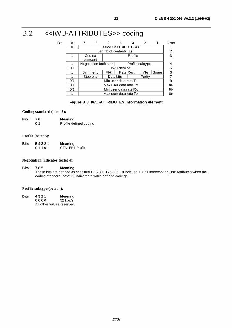
B.2 <<IWU-ATTRIBUTES>> codingBit: 8 7 6 5 4 3 2 1 Octet
0 <<IWU-ATTRIBUTES>> 1Length of contents (L) 2
1 Codingstandard
Profile 3
1 Negotiation Indicator Profile subtype 40/1 IWU service 51 Symmetry Fbk Rate Res. Mfe Spare 61 Stop bits Data bits Parity 7
0/1 Min user data rate Tx 80/1 Max user data rate Tx 8a0/1 Min user data rate Rx 8b1 Max user data rate Rx 8c
Figure B.8: IWU-ATTRIBUTES information element
Coding standard (octet 3):
Bits 7 6 Meaning0 1 Profile defined coding
Profile (octet 3):
Bits 5 4 3 2 1 Meaning0 1 1 0 1 CTM-FP1 Profile
Negotiation indicator (octet 4):
Bits 7 6 5 MeaningThese bits are defined as specified ETS 300 175-5 [5], subclause 7.7.21 Interworking Unit Attributes when thecoding standard (octet 3) indicates "Profile defined coding".
Profile subtype (octet 4):
Bits 4 3 2 1 Meaning0 0 0 0 32 kbit/sAll other values reserved.

ETSI
Draft EN 302 096 V0.2.2 (1999-03)24
IWU service (octet 5):
Bits 7 6 5 4 3 2 1 Meaning0 0 0 0 0 0 0 Unspecified V.series voice-band modem0 0 0 0 0 0 1 V.210 0 0 0 0 1 0 V.220 0 0 0 0 1 1 V.22 bis0 0 0 0 1 0 0 V.230 0 0 0 1 0 1 V.26 bis0 0 0 0 1 1 0 V.26 ter0 0 0 0 1 1 1 V.270 0 0 1 0 0 0 V.27 ter0 0 0 1 0 0 1 V.320 0 0 1 0 1 0 V.32 bis0 0 0 1 0 1 1 V.340 0 0 1 1 0 0 V.1100 0 0 1 1 0 1 V.1200 0 0 1 1 1 0 V.240 0 0 1 1 1 1 32 kbit/s unprotected0 0 1 1 0 0 0 H.324 via 32 kbit/s (DECT annex)0 0 1 1 0 0 1 ATM AAL-11 1 1 1 1 1 1 EscapeAll other values reserved.
Symmetry (octet 6):
Bits 7 6 Meaning0 0 Asymmetric, full duplex0 1 Symmetric, full duplexAll other values reserved.
Fbk (octet 6):
Bits 5 Meaning0 Bit rate fall back supported1 Bit rate fall back not supported
Rate Resolution (octet 6):
Bits 4 3 Meaning0 0 n × 2,4 kbit/s0 1 n × 4 kbit/sAll other values reserved.
Mfe (Multiple frame establishment, octet 6):
This information element is included for compatibility with ITU-T Recommendation V.120 [18].
Bits 2 Meaning0 Multiple frame establishment not supported, only UI frames allowed1 Multiple frame establishment supported

ETSI
Draft EN 302 096 V0.2.2 (1999-03)25
Stop bits (octect 7):
This information element is included for compatibility with ITU-T Recommendation V.120 [18].
Bits 7 6 Meaning0 0 Not used0 1 1 bit1 0 1.5 bits1 1 2 bits
Data bits (octect 7):
This information element is included for compatibility with ITU-T Recommendation V.120 [18].
Bits 5 4 Meaning0 0 Not used0 1 5 bits1 0 7 bits1 1 8 bits
Parity (octect 7):
This information element is included for compatibility with ITU-T Recommendation V.120 [18].
Bits 3 2 1 Meaning0 0 0 Odd0 1 0 Even0 1 1 None1 0 0 Forced to 01 0 1 Forced to 1
Min user data rate Tx (octet 8):
If the user data rate resolution in octet 6 (bits 3-4) indicate 'n × 2,4 kbit/s' then:
Bits 7 6 5 4 3 2 1 Meaning0 0 0 0 0 0 0 0 kbit/s0 0 0 0 0 0 1 2,4 kbit/s0 0 0 0 0 1 0 4,8 kbit/s0 0 0 0 0 1 1 7,2 kbit/s0 0 0 0 1 0 0 9,6 kbit/s0 0 0 0 1 0 1 12 kbit/s0 0 0 0 1 1 0 14,4 kbit/s0 0 0 0 1 1 1 16,8 kbit/s0 0 0 1 0 0 0 19,2 kbit/s0 0 0 1 0 0 1 21,6 kbit/s0 0 0 1 0 1 0 24 kbit/s0 0 0 1 0 1 1 26,4 kbit/s0 0 0 1 1 0 0 28,8 kbit/sAll other values reserved.
If the user data rate resolution in octet 6 (bits 3-4) indicate 'n × 4 kbit/s' then:
Bits 7 6 5 4 3 2 1 Meaning0 0 0 0 0 0 0 0 kbit/s0 0 0 0 0 0 1 4 kbit/s0 0 0 0 0 1 0 8 kbit/s0 0 0 0 0 1 1 12 kbit/s0 0 0 0 1 0 0 16 kbit/s0 0 0 0 1 0 1 20 kbit/s0 0 0 0 1 1 0 24 kbit/s0 0 0 0 1 1 1 28 kbit/sAll other values reserved.

ETSI
Draft EN 302 096 V0.2.2 (1999-03)26
Max user data rate Tx (octet 8a) (optional):
This octet is optional. If omitted, the max user data rate Tx shall be interpreted as equal to the rate indicated by octet 8and octets 8b and 8c shall not be included.
Bits 7 6 5 4 3 2 1 MeaningThe coding of these bits is identical to the coding of bits 1-7 of octet 8.
Min user data rate Rx (octet 8b) (optional):
This octet is optional. If omitted, the min user data rate Rx shall be interpreted as equal to the rate indicated by octet 8and octet 8c shall not be included.
Bits 7 6 5 4 3 2 1 MeaningThe coding of these bits is identical to the coding of bits 1-7 of octet 8.
Max user data rate Rx (octet 8c) (optional):
This octet is optional. If omitted the max user data rate Rx shall be interpreted as equal to the rate indicated by octet 8b.
Bits 7 6 5 4 3 2 1 MeaningThe coding of these bits is identical to the coding of bits 1-7 of octet 8.

ETSI
Draft EN 302 096 V0.2.2 (1999-03)27
BibliographyThe following material, though not specifically referenced in the body of the present document (or not publiclyavailable), gives supporting information.
DE/NA-020066: "Cordless Terminal Mobility (CTM); Phase 2+ Feature Package 1 (FP1); 64 and 32 kbit/s UnrestrictedDigital Information (UDI)".
EN 300 176-1: "Digital Enhanced Cordless Telecommunications (DECT); Approval test specification; Part 1: Radio".
TBR 22: "Radio Equipment and Systems (RES); Attachment requirements for terminal equipment for Digital EnhancedCordless Telecommunications (DECT) Generic Access Profile (GAP) applications".

ETSI
Draft EN 302 096 V0.2.2 (1999-03)28
History
Document history
V0.2.2 March 1999 Public Enquiry PE 9927: 1999-03-05 to 1999-07-02