copyright warning &...
TRANSCRIPT

Copyright Warning & Restrictions
The copyright law of the United States (Title 17, United States Code) governs the making of photocopies or other
reproductions of copyrighted material.
Under certain conditions specified in the law, libraries and archives are authorized to furnish a photocopy or other
reproduction. One of these specified conditions is that the photocopy or reproduction is not to be “used for any
purpose other than private study, scholarship, or research.” If a, user makes a request for, or later uses, a photocopy or reproduction for purposes in excess of “fair use” that user
may be liable for copyright infringement,
This institution reserves the right to refuse to accept a copying order if, in its judgment, fulfillment of the order
would involve violation of copyright law.
Please Note: The author retains the copyright while the New Jersey Institute of Technology reserves the right to
distribute this thesis or dissertation
Printing note: If you do not wish to print this page, then select “Pages from: first page # to: last page #” on the print dialog screen

The Van Houten library has removed some of the personal information and all signatures from the approval page and biographical sketches of theses and dissertations in order to protect the identity of NJIT graduates and faculty.

ABSTRACT
BRAIN COMPUTER INTERFACE BASED NEUROREHABILITATIONTECHNIQUE USING A COMMERCIALLY AVAILABLE EEG HEADSET
byAbhineet Mishra
Neurorehabilitation has recently been augmented with the use of virtual reality and
rehabilitation robotics. In many systems, some known volitional control must exist in
order to synchronize the user intended movement with the therapeutic virtual or robotic
movement. Brain Computer Interface (BCI) aims to open up a new rehabilitation option
for clinical population having no residual movement due to disease or injury to the
central or peripheral nervous system. Brain activity contains a wide variety of electrical
signals which can be acquired using many invasive and non-invasive acquisition
techniques and holds the potential to be used as an input to BCI. Electroencephalogram
(EEG) is a non-invasive method of acquiring brain activity which then, with further
processing and classification, can be used to predict various brain states such as an
intended motor movement. EEG provides the temporal resolution required to obtain
significant result which may not be provided by many other non-invasive techniques.
Here, EEG is recorded using a commercially available EEG headset provided by Emotiv
Inc. Data is collected and processed using BCI2000 software, and the difference in the
Mu-rhythm due to Event Related Synchronization (ERS) and Desynchronization (ERD)
is used to distinguish an intended motor movement and resting brain state, without the
need for physical movement. The idea is to combine this user intent/free will with an
assistive robot to achieve the user initiated, repetitive motor movements required to bring
therapeutic changes in the targeted subject group, as per Hebbian type learning.

BRAIN COMPUTER INTERFACE BASED NEUROREHABILITATIONTECHNIQUE USING A COMMERCIALLY AVAILABLE EEG HEADSET
byAbhineet Mishra
A ThesisSubmitted to the Faculty of
New Jersey Institute of Technologyin Partial Fulfillment of the Requirements for the Degree of
Master of Science in Biomedical Engineering
Department of Biomedical Engineering
May 2013

APPROVAL PAGE
BRAIN COMPUTER INTERFACE BASED NEUROREHABILITATIONTECHNIQUE USING A COMMERCIALLY AVAILABLE EEG HEADSET
Abhineet Mishra
Dr. Richard A. Foulds, Thesis Advisor DateAssociate Professor of Biomedical Engineering, NJIT
Dr. Sergei Adamovich, Committee Member DateAssociate Professor of Biomedical Engineering, NJIT
Dr. Mesut Sahin, Committee Member DateAssociate Professor of Biomedical Engineering, NJIT

BIOGRAPHICAL SKETCH
Author: Abhineet Mishra
Degree: Master of Science
Date: May 2013
Undergraduate and Graduate Education:
• Master of Science in Biomedical Engineering,New Jersey Institute of Technology, Newark, NJ, 2013
• Bachelor of Technology in Electronics and Communication Engineering,Rajasthan Technical University, Kota, Rajasthan, India, 2010
Major: Biomedical Engineering
Presentations and Publications:
Abhineet Mishra and Richard A. Foulds, "Detection of user intent in neurorehabilitationusing a commercial EEG headset," 39th Annual Northeast BioengineeringConference, IEEE, 2013.
Abhineet Mishra, Deniz Ozgulbas, Eren Alay, Eun Kim, Tara L. Alvarez, " Checking thesaliency of the stimuli on central versus peripheral visual field ," 39th AnnualNortheast Bioengineering Conference, IEEE, 2013.
iv

v
To my parents for their love and supportand mentors for having faith in me.

vi
ACKNOWLEDGEMENT
I would like to start by thanking my mentor Dr. Bhaskar Mohan Murari, who is the
reason behind me pursuing a career as a Biomedical Engineering. Without his motivation
and contagious idealism this thesis wouldn’t have been possible. I would also like to
thank my undergraduate advisor Mr. Avisek Ghose for developing a sense of
responsibility in me towards our community.
I would especially like to thank my graduate thesis advisor Dr. Richard Foulds
and defense committee members Dr. Sergei Adamovich and Dr. Mesut Sahin, for putting
their faith in my ideas, providing me with all the necessary equipment’s and
infrastructure and allowing me to work on it. Just because of their constant input and
feedbacks this work has reached to the stage; where I was able to test it on human
subjects to check its efficacy as a rehabilitation system. This wouldn’t have been possible
without your guidance and endless patience.
I am indebted to Dr. Denis McFarland, the man behind curtain, for consistently
providing me with the ideas to solve all my problems. He was my savior during those
dark phases and dead ends, where I felt that, I’ll never be able to achieve positive results.
He was always there to pull me out of those pits and direct me on a lighted path.
Last but not least, I would like to thank my family, friends and foes for motivating
me directly or indirectly to achieve my goal in life.
vii
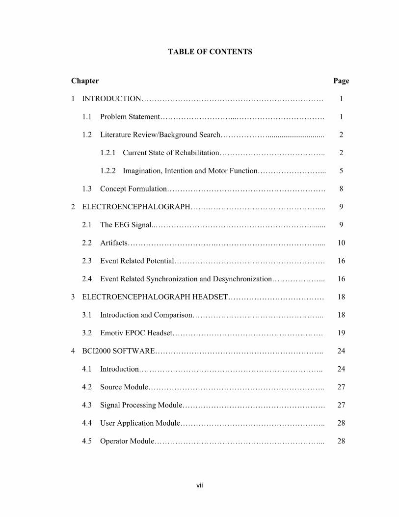
TABLE OF CONTENTS
Chapter Page
1 INTRODUCTION……………………………………………………………. 1
1.1 Problem Statement………………………...……………………………. 1
1.2 Literature Review/Background Search………………............................. 2
1.2.1 Current State of Rehabilitation………………………………….. 2
1.2.2 Imagination, Intention and Motor Function……………………... 5
1.3 Concept Formulation……………………………………………………. 8
2 ELECTROENCEPHALOGRAPH…….…………………………………….... 9
2.1 The EEG Signal..……………………………………………………....... 9
2.2 Artifacts…………………………….………………………………….... 10
2.3 Event Related Potential…………………………………………………. 16
2.4 Event Related Synchronization and Desynchronization………………... 16
3 ELECTROENCEPHALOGRAPH HEADSET………………………………. 18
3.1 Introduction and Comparison…………………………………………... 18
3.2 Emotiv EPOC Headset…………………………………………………. 19
4 BCI2000 SOFTWARE……………………………………………………….. 24
4.1 Introduction…………………………………………………………….. 24
4.2 Source Module………………………………………………………….. 27
4.3 Signal Processing Module………………………………………………. 27
4.4 User Application Module……………………………………………….. 28
4.5 Operator Module………………………………………………………... 28

viii
4.6 Interfacing Emotiv Headset with BCI2000……………………………... 29
5 EXPERIMENTAL DESIGN………………………………………………….. 33
5.1 Design and Implementation……………………………………………... 33
5.2 Test Run and Offline Analysis………………………………………….. 37
5.3 Biofeedback and Neuroplasticity……………………………………….. 42
6 RESULTS AND CONCLUSIONS………..……………………………..…... 46
7 APPENDIX A.……………………………………………………………….. 48
8 APPENDIX B………………………………………………………………… 57
9 REFERENCES……………………………………………………………….. 58

ix
LIST OF TABLES
Table Page
2.1 Overview over some artifact types and their amplitude/frequency……..ranges.
11
3.1 Low-cost EEG systems under $1000…………………………………... 19
6.1 Performance of healthy subjects in the cursor control task…………….. 46

x
LIST OF FIGURES
Figure Page
1.1 Classification of rehabilitation approaches post stroke……………… 2
1.2 Motek’s virtual environment with assistive treadmill for gait….……training.
4
2.1 Cortical generators of electric currents……………………….……… 10
2.2 How eye-movements and blinks influence the EEG recording….…... 12
2.3 Electromyogram (muscle) artifact…………………………………… 14
2.4 Artifacts due to power line interference……………………………… 14
2.5 Electrocardiogram (heart beat) artifact………………………………. 15
2.6 Schema for the generation of induced (ERD/ERS) and evoked (ERP)activity whereby the former is highly frequency-specific. TCRthalamic relay cells; RE reticular thalamic nucleus.
17
3.1 Usability rating of low budget EEG acquisition devices…………….. 19
3.2 Emotiv EPOCTM EEG headset. The black pads placed right behind...the ears are non-conducive reference electrodes.
21
3.3 Points for EEG recording electrodes (international 10-20 electrode…system).Electrode A1 is point for reference electrode connection
22
3.4 Electrodes placement of Emotiv EPOC headset as per 10-20…….….placement system.
23
3.5 Emotiv EPOC headset placement……………………………….…… 23
4.1 BCI2000 design, consisting four modules…………………………… 26
4.2 Displays for the three BCI2000 user applications………………..….. 29
4.3 Batch folder under the BCI2000 installation directory………………. 30
4.4 Parameters for Emotiv EPOC headset…………………………….…. 32

xi
5.1 Emotiv EPOC headset felt sensors soaked in saline solution……...... 35
5.2 Training session application window………………………………… 36
5.3 Homunculus of the motor area showing the enormousness of the.......hands
37
5.4 Data acquired via 14 channels of Emotiv EPOC headset................... 38
5.5 BCI2000 offline analysis tool............................................................. 39
5.6 R-squared value between imagination and rest.................................... 40
5.7 Spectra and the r-squared value on the selected channels.................... 40
5.8 Difference in the spectra after using Laplacian and CAR filters.......... 41
5.9 Virtual environment giving a visual feedback of hand opening and...closing.
42

xii
LIST OF ACRONYMS
BCI Brain Computer Interface
BMI Brain Machine Interface
EEG Electroencephalogram
EMG Electromyogram
CVA Cerebrovascular Accidents
TBI Traumatic Brain Injury
SCI Spinal Cord Injury
ALS Amyotrophic Lateral Sclerosis
EOG Electrooculogram
ECG Electrocardiogram
EP Evoked Potential
ERP Event Related Potential
MEG Magnetoelectroencephalogram
ERD Event Related Desynchronization
ERS Event Related Synchronization
TCP/IP Transmission Control Protocol/Internet Protocol
UDP User Datagram Protocol
CAR Common Average Reference
VRML Virtual Reality Modeling Language
VR Virtual Reality

1
CHAPTER 1
INTRODUCTION
1.1 Problem Statement
Cerebrovascular Accidents (CVA), commonly known as Stroke, Traumatic Brain Injury
(TBI), Spinal Cord Injury (SCI), Amyotrophic Lateral Sclerosis (ALS) are few among
many diseases severely affecting the channel of interaction between brain and its
operated entities [1]. In the United States, they are the leading cause of disability
affecting over a million individuals annually and substantially more across the globe [1]
[2] [3]. As per the National Stroke Association, after a year post stroke, a third of all
affected patients have poor or non-existent residual hand motor function, despite
intensive treatment and rehabilitation. Significant functional recovery after this initial
year is rare despite novel interventional approaches recently applied in the chronic stage,
like bilateral arm training or constraint-induced movement therapy [4] [5]. The associated
treatment cost also ranges between $100K and $2M, which includes inpatient care,
rehabilitation, and follow-up [2] [6].
Currently available treatments deeply rely on the ability of the patient to perform
actions with the affected arm or hand, and therefore require a moderate degree of residual
motor function. There are however, many patients who do not have such residual
function and therefore cannot use the plegic hand at all for training purposes. At present,
there is no treatment available for this condition. Under such condition a brain computer
interface (BCI) system which decodes brain signals to identify end-effecter action or
behavior can provide an effective & affordable rehabilitation system.

2
1.2 Literature Review/Background Search
Many different approaches have been used rehabilitate subjects who have had
cerebrovascular accidents. But the novelty of this approach is the synchronization
between the intention to move and the movement of a robot. This effectively allows the
therapeutic movement to be triggered by the user’s imagination.
1.2.1 Current State of Rehabilitation
Traditional approaches towards rehabilitation can be qualified as bottom-up approaches.
They act on the distal physical level (bottom) aimed at influencing the neural system
(top), with resulting rehabilitation due to the mechanism of neural plasticity. Another
approach is the top-bottom defining the rehabilitation therapies based on the state of the
brain after stroke, driven by neural plasticity. Detailed classification is shown in the
figure 1.1.
Figure 1.1: Classification of rehabilitation approaches post stroke.Source: [7]

3
Apart from all these techniques other factors also affect the rehabilitation
outcomes; these include a high degree of motivation and involvement/engagement of
patients with their family, cognitive functions and attention. Sometimes these factors also
influence the inclusion or exclusion criteria for the subjects in research studies.
Conventional bottom-top approaches do not restore a normal gait pattern in the
majority of stroke patients [8] giving reason to use robots in assistive training for both
upper and lower extremity. These devices provide safe, intensive, and task oriented
rehabilitation to people with mild to severe motor impairments after neurological injury
[9]. In principle, robotic training could increase the intensity of therapy with quite
affordable costs, and offer advantages such as: i) precisely controllable assistance or
resistance during movements, ii) good repeatability, iii) objective and quantifiable
measures of subject performance, iv) increased training motivation through the use of
interactive (bio)feedback. In addition, this approach reduces the amount of physical
assistance required to walk reducing health care costs [10] and provides kinematic and
kinetic data in order to control and quantify the intensity of practice, measure changes
and assess motor impairments with better sensitivity and reliability than standard clinical
scales [9] [10] [11]. Combined with a visual feedback provided via immersive virtual
environment (see Figure 1.2) they can prove out to be an effective method of
rehabilitating stroke subjects [12] [13]. Virtual environment provides some added
advantages like:
Real-time feedback - Therapists and patients receive real-time feedback.
Inspiring and motivational - Thanks to gaming elements, training becomesinspiring and motivational. Being immersed in a game environment often has aneffect where patients stop concentrating on their limitations and pain. Positivefeedback is given to stimulate patients.

4
Controlled environment - The therapist can customize challenging exercises in avery controlled environment. Different levels of difficulty can be applied bygiving feedback to the patient through loop speed and gain based on patient’sperformance.
Figure 1.2: Motek’s virtual environment with assistive treadmill for gait training.
Source: [14]
Limitation with this extra-ordinarily effective method of providing therapy is in
its inclusion criteria. All such therapy requires a certain degree of voluntary movement
post stroke i.e. if a subject cannot move their limb at all, they cannot benefit from
robotic-virtual environment therapy.

5
1.2.2 Imagination, Intention and Motor functions
The Human brain is like a black box containing the neural representation of the actions,
behavior, responses etc. It would be best if one could somehow steer into it to get full
access to its endogenous functioning and get answers to many intriguing questions. But,
reality is slightly opaque, forcing researchers and clinicians to rely on introspections,
mental chronometry and inference of cognitive brain functions from measurements of
remote physiological correlates.
Action representation is one of such issues, having conflicting point of views.
Some mechanisms consider it to be internally represented/ endogenously driven whereas
other found it to be direct transformation of ingoing activity into outgoing activity [15].
Following the former, it can be warranted that motor imagery, when defined and used
properly can be a key to understanding motor representations and the cognitive content of
actions.
Imagination is the ability to form images and sensations that are not perceived
through sight, hearing or other senses. It is further classified into two types: Visual
Imagery and Motor Imagery. Visual imagery refers to the imagination of visual
representation of the scenes, for example, imagining a fruit or any flower. Whereas,
motor imagery refers to the visual images related to the action. It is further classified into
two types: internal and external. If one imagines a limb movement, he/she can imagine it
as first person i.e. individual is doing that task themselves or as a second person i.e.
imagining somebody doing that action. This study focuses only on internal motor
imagery. A close functional equivalence between motor imagery and motor preparation is
suggested by the positive effects of imagining movements on motor learning, the

6
similarity between the neural structures involved, and the similar physiological correlates
observed in both imaging and preparation [15]. The reason for taking imagery to be in
close relation with action preparation/ intention is its ability to conserve the spatial-metric
property, i.e. the time needed to perform an actual action like picking up an object from a
table is found to be equal to the time taken to perform the same task in imagination [15].
Its vividness can also be understood by the change in heart and respiration rate of an
individual while watching an involving sport. The idea is that we feel our self to be so
immersed in the sports that our brain starts to respond as if we are not only watching but
playing that game as well. It was better explained with the theory of mind and discovery
of mirror neurons.
During 1980s and 1990s, a remarkable thing was discovered inside a macaque
brain by a group of Italian neurophysiologists. This discovery was not accepted initially
but was widely supported by the scientific community with time. That thing is known as
‘Mirror Neuron’, and with the help of advances in non-invasive technologies like fMRI
and PET Scans, it was later on found to exist in human brain as well [16] [17]. Using
microelectrodes that recorded from individual neurons, those Italian investigators
observed that the same neuron fired both when the monkey grasped an object, such as a
raisin, and when it observes a human or another monkey performing the same specific
action. Mirror neurons respond only to intentional motor actions. This is the first
evidence that there is an area in the motor cortex that can respond specifically and only to
goal-directed, relational actions. To illustrate, consider a pupil learning a motor skill like
learning a musical instrument. While pupil watches the teacher, neurons in his brain
relevant to motor preparation and planning will fire as if he were actually preparing the

7
action he is viewing. Similarly, the teacher’s feeling during pupil’s performance would be
based on the discharge of the same neurons in his own brain that were firing while he was
preparing and executing the correct movements. This very striking result supports the
idea of representing neurons as a common substrate for motor preparation and imagery.
Motor images and motor preparation have different subjective contents. Only the
final content of motor preparation is open to the subject’s judgment, so the action, once
executed, can be recognized by him to correspond (or not) to his intent. By contrast, the
content of motor images can be accessed consciously. This difference between the two
situations may be one of degree, however, rather than one of kind, in which case if motor
preparation (normally very brief) could be prolonged, the intention to act would
progressively become a motor image of the same action. If this were the case, the non-
conscious to conscious transition would be determined by solely by the time allowed for
the preparation processes to access awareness [15]. This idea of getting access to
intention when it is not followed by execution was further supported by studies on
amputees. They reported, that amputees seem to have clear image of their intended action
[18]. These data suggests that if the action were actually executed, the content of the
motor representation would not reach consciousness because it would be cancelled as
soon as the corresponding movement is executed (perhaps by the incoming signal
generated by execution itself). By contrast, if only motor imagery occurred with
execution deliberately blocked or delayed, the representation would be protected from
cancellation and would become accessible to conscious processing.

8
1.3 Concept Formulation
Access to the intention/conscious free will via imagination opens the gate for the clinical
population with no residual movement (post stroke) to benefit from robot assisted,
immersive virtual environment training. A Brain computer interface system can allow
accessing the intentions of the subject within 200msec which is close to average human
response time to visual stimuli [19]. The core of this whole rehabilitation method is to
synchronize the intended movement of the subject with robot assisted execution and
virtual environment feedback. It will be a perfect top-bottom approach of the
rehabilitation, exploiting neuroplasticity to rehabilitate subjects not depending on the
expected activation in peripheral limb. The hypothesis and expected result post training is
that, with time subject will gain strength to move their affected limb on their own or with
minimal assistance.
Secondarily, effectiveness of a commercially available and cost effective EEG
headset is also analyzed towards brain computer interface, with an idea to make this
system cost effective. Whether, it is possible to use them to detect EEG features and
identify changes in the brain states to independently control the rehabilitation system.
Since, the user is expected to cooperate and imagine the exact movement replicated by
the robot, all that is needed by a BCI system is a signal indicating initiation of the
imagined movement to allow its synchronization with the robot movement. This produces
the requirement of the BCI system to distinguish a resting state with motor imagination or
movement.

9
Chapter 2
ELECTROENCEPHALOGRAPH
2.1 The EEG Signal
It is not possible to measure a single neuron’s action potential extracellularly, as its
amplitude is too small to be picked up by the EEG. It does not last long enough (0.3ms)
to accumulate sufficient power together with other synchronously firing neurons [20].
Release of neurotransmitters to the synapse is triggered when an action potential reaches
the axon terminal [21]. There exist two kinds of neurotransmitters: one causes an influx
and the other an outflow of positive ions by changing the permeability of the postsynaptic
neuron’s membrane [22] and thereby influences the neuron’s potential difference.
This is referred to as either excitatory postsynaptic potential (when positive) or
inhibitory postsynaptic potential (when negative) [23]. Postsynaptic potentials vary in
their amplitude between 50 and 100mV (measurement on the scalp) [20], last over 100ms
[24] and constitute the main source of the EEG-signal.
For an electrical signal to be strong enough to be detectable the following
requirements have to be satisfied [21]:
many neurons must fire synchronously
those neurons must be aligned in parallel so that their potential sum rather thancancel out (see figure 2.1)

10
Figure 2.1: Cortical generators of electric currents. Thick arrows represent thepropagation of electrical currents that can be picked up by the EEG electrode.
Source: [25]
The electroencephalography is defined as a graphic representation of the potential
difference between two different cerebral locations plotted over time [26]. It is important
to note here that the signal of each channel is always plotted as the difference to a
reference electrode, even though the name of the reference channel is often omitted.
2.2 Artifacts
As discussed earlier, EEG is designed to record cerebral activity, but it also picks up
electrical activities arising from locations other than the brain. The recorded activity that
is not of cerebral origin is termed artifact and can be divided into physiological and extra
physiological artifacts. While physiological artifacts are generated from the patient, they

11
arise from sources other than the brain (i.e., body). Extra physiologic artifacts arise from
outside the body (i.e., equipment, environment).
Electrical activities arising from muscle, also known as myogenic potentials are
the most common artifacts. The frontalis and temporalis muscles (e.g., clenching of jaw
muscles) are common sources. Generally, the potentials generated in the muscles are of
shorter duration than those generated in the brain and are identified easily on the basis of
duration, morphology, and rate of firing (i.e., frequency). Particular patterns of
electromyogram (EMG) artifacts can occur in some movement disorders. Essential
tremor and Parkinson disease can produce rhythmic 4 to 6 Hz sinusoidal artifacts that
may mimic cerebral activity.
Table 2.1: Overview over some artifact types and their amplitude/frequency ranges. Itshould be noted, that those properties refer to measurements being taken as close aspossible to the origin of the electrical activity, which is in the skin area closest to theskeletal muscle.
Source: [27]
Biological artifacts can be broadly classified into multiple categories which
includes Eye-induced artifacts (eye blinks, eye movements and extra-ocular muscle
activity), ECG artifacts, Muscle activity-induced artifacts and Glossokinetic artifact
(artifacts are caused by the potential difference between the base and the tip of the
tongue).

12
Eye movements are observed on all EEGs and are useful in identifying sleep
stages [28]. The eyeball acts as a dipole with a positive pole oriented anteriorly (cornea)
and a negative pole oriented posteriorly (retina). When the globe rotates about its axis, it
generates a large-amplitude alternate current field, which is detectable by any electrodes
near the eye (see Figure 2.2).
Figure 2.2: How eye-movements and blinks (right) influence the EEG recording (left).All y-axis scaling are in µV.
Source: [27]
The Electromyogram (EMG) measures electrical currents generated in muscles
during its contraction representing neuromuscular activities. The EMG signal also
influences the EEG recording as illustrated in figure 2.3. It is therefore important to
inform the patient about it so that he can try to move as little as possible during the
recording. Also EMG artifacts should be considered when designing an experiment: The
patient should be seated comfortably and should not be required to move or turn his head

13
during the experiment. If possible, pauses might be built into the experiment that the
patient can use to move.
Some individual variations in the amount and persistence of ECG artifact are
related to the field of the heart potentials over the surface of the scalp. Generally, people
with short and wide necks have the largest ECG artifacts on their EEGs. The voltage and
apparent surface of the artifact vary from derivation to derivation. The artifact is observed
best in referential montages using earlobe electrodes A1 and A2. ECG artifact is
recognized easily by its rhythmicity/regularity and coincidence with the ECG tracing
(each "sharp wave" equals artifact that synchronizes with each QRS complex of the ECG
channel; see Figure 2.4). The situation becomes difficult when cerebral abnormal activity
(e.g., sharp waves) appears intermixed with EEG artifact, and the former may be
overlooked.

14
Figure 2.3: Electromyogram (muscle) artifact (marked in red). These waveformsrepresent motor unit potentials as typically observed on needle electrode examinationduring electromyogram, with a frequency of 20-100 Hz.
Source: [29]
Figure 2.4: Artifacts due to power line interference. This figure shows an example forone signal channel (marked by the arrow) that is contaminated by regular high frequency(i.e., 60 Hz) noise.
Source: [30]

15
Figure 2.4: Regular (periodic) slow wave’s best observed at mid temporal and posteriortemporal electrodes T4-T6 and T3-T5 (shown in red). These clearly are related to ECG.The duration and morphology are those of pulse artifact, but as demonstrated by themarker, no delay occurs between the ECG and the artifact. Thus, this is an ECG artifactwith broad QRS complexes.
Source: [29]
In addition to these artifacts, the tongue (like the eyeball) functions as a dipole,
with the tip negative with respect to the base. In this case, the tip of the tongue is the most
important part because it is more mobile. The artifact produced by the tongue has a broad
potential field that drops from frontal to occipital areas, although it is less steep than that
produced by eye movement artifacts. Chewing and sucking can produce similar artifacts.
These are commonly observed in young patients. However, they also can be observed in
patients with dementia or those who are uncooperative.
16
2.3 Event Related Potentials
Event-related potentials (ERPs) are very small voltages generated in the brain structures
in response to specific events or stimuli [31]. They are EEG changes that are time locked
to sensory, motor or cognitive events that provide safe and noninvasive approach to study
psychophysiological correlates of mental processes. Event-related potentials can be
elicited by a wide variety of sensory, cognitive or motor events. They are thought to
reflect the summed activity of postsynaptic potentials produced when a large number of
similarly oriented cortical pyramidal neurons (in the order of thousands or millions) fire
in synchrony while processing information [32]. Positive and negative potential changes
are commonly labeled with either “P” (for positive) or “N” (for negative) and a number
corresponding to the time of their appearance relative to the event [21]. Consequently,
N400 represents a negative peak 400ms after the event.
2.4 Event Related Synchronization and Desynchronization
An internally or externally paced event results not only in the generation of an event-
related potential (ERP) but also in a change in the ongoing EEG/MEG in form of an
event-related desynchronization (ERD) or event-related synchronization (ERS) (see
Figure 2.5). The ERP on the one side and the ERD/ERS on the other side are different
responses of neuronal structures in the brain. While the former is phase-locked, the latter
is not phase-locked to the event. The most important difference between both phenomena
is that the ERD/ERS is highly frequency band specific, whereby either the same or
different locations on the scalp can display ERD and ERS simultaneously [33]. There are
a couple of event-related phenomena which represent frequency specific changes of the
17
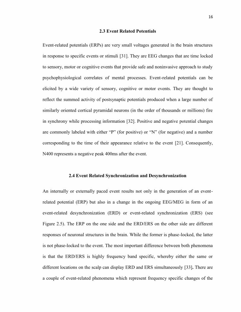
ongoing EEG activity (motor imagery being one of those) and may consist, in general
terms, either of decreases or of increases of power in given frequency bands. This may be
considered to be due to a decrease or an increase in synchrony of the underlying neuronal
populations, respectively. The former case is called event-related desynchronization or
ERD and the latter event-related synchronization (ERS) [33].
Figure 2.5: Schema for the generation of induced (ERD/ERS) and evoked (ERP) activitywhereby the former is highly frequency-specific. TCR thalamic relay cells; RE reticularthalamic nucleus.
Source: [33]

18
Chapter 3
ELECTROENCEPHALOGRAPH HEADSET
3.1 Introduction and Comparison
An EEG has a very high time resolution, i.e. changes in electrical activity of the brain
show up very quickly in the signal of the EEG (Also it is non-invasive and relatively user
friendly). EEG headsets serve the purpose of acquiring these electrical activities from the
scalp just like any other set of sophisticated electrode cap and amplifier. They measure
voltage fluctuations resulting from ionic current flow within the brain. Compared to other
professional EEG systems, performance of these headsets are low [34] and are
completely subject dependent. But since it was never meant to be used as a medical
device they serve the purpose of their manufacturers and users. It is very much capable of
differentiating between brain states but subject needs to pay full attention and become
familiar with what state of mind they are in. Such headset attracts hobbyists and may
soon allow use of EEGs for the consumer. In a study, different low-cost EEG systems
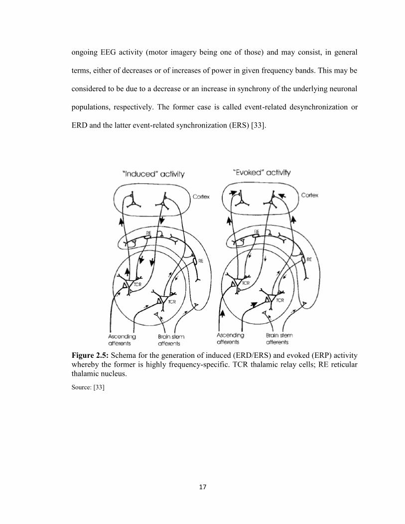
have been compared by price and functionality (see Table 3.1) and rated by usability (see
Figure 3.1). In their findings, the Emotiv EPOC scored best in terms of usability and was
ranged in the middle price segment [35].
19
Table 3.1: Low-cost EEG systems under $1000.
Source: [35]
Figure 3.1: Usability rating of low budget EEG acquisition devices.
Source: [35]
3.2 Emotiv EPOC Headset
The Emotiv headset is an attempt to bring EEG capabilities to the masses. At $299.00
($750.00 for the research SDK), the headset is relatively affordable. These “gaming EEG
systems” use EEG activity to control the movement of characters or objects in games via
headsets that comprise a small array of sensors that are:

20
Wirelessly connected to software that runs on a laptop, the user maintains a fullrange of motion
Require little adjustment of electrodes, so no need for long electrode placementprocedures.
Typically use small foam tipped felt sensors that are soaked in saline solution toconnect each electrode to the scalp, so no need for messy gel, and hence no needfor head washing.
The gaming EEG system (i.e., Emotiv EPOC®) used gold-plated contact-sensors
that were fixed to flexible plastic arms of a wireless headset. The headset included 16
sites, aligned with the 10–20 system: AF3, F7, F3, FC5, T7, P7, O1, O2, P8, T8, FC6, F4,
F8, FC4, M1, and M2. One mastoid (M1) sensor acted as a ground reference point to
which the voltage of all other sensors was compared. The other mastoid (M2) was a feed-
forward reference that reduced external electrical interference. The signals from the other
14 scalp sites (channels) were high-pass filtered with a 0.16 Hz cut-off, pre-amplified and
low-pass filtered at an 83 Hz cut-off. The analogue signals are then digitized at 2048 Hz.
The digitized signals are filtered using a 5th-order sinc notch filter (50–60 Hz), low-pass
filtered and down-sampled to 128 Hz (specifications taken from the gaming EEG system
web forum). The effective bandwidth is 0.16–43 Hz.

21
Figure 3.2: Emotiv EPOCTM EEG Headset. The black pads placed right behind the earsare non-conducive reference electrodes.
Source: [36]

22
Figure 3.3: Points for EEG recording electrodes (international 10-20 electrodesystem).Electrode A1 is point for reference electrode connection.
Source: [37]

23
Figure 3.4: Electrodes placement of Emotiv EPOC Headset as per 10-20 placementsystem.
Source: [38]
Figure 3.5: Emotiv EPOC Headset placement. Sensors with the black rubber should beplaced on the bone just behind each ear lobe. Correct placement of the rubber sensor iscritical for correct operation (Top). 2 front sensors should be approximately at thehairline or about the width of 3 fingers above your eyebrows. Press and hold the 2reference sensors (located just above and behind the ears) for about 5-10 seconds(Bottom).
Source: [39]
24
CHAPTER 4
BCI2000 SOFTWARE
4.1 Introduction
As described in the previous chapters, many factors determine the performance of a BCI
system. These factors include the brain signals measured, the signal processing methods
that extract signal features, the algorithms that translate these features into device
commands, the output devices that execute these commands, the feedback provided to the
user, and the characteristics of the user. Thus, future progress requires systematic well-
controlled studies that evaluate and compare alternative signals and combinations of
signals, alternative feature extraction methods and translation algorithms, and alternative
communication and control applications in different user populations. In consequence, a
typical research and development program focused on human BCI research will usually
run several studies at the same time, possibly even in different locations, and most often
by different personnel. These requirements imply the need for a software tool that
facilitates the implementation of any BCI system, and that facilitates the collaboration of
multiple laboratories on algorithm design, experimental design, or data analysis. In other
words, standardized software or procedural mechanisms for development of BCI methods
and their components, for data exchange, and for the appropriate documentation of
relevant configuration parameters are necessary. BCI2000 is a documented general-
purpose BCI research and development platform. It can incorporate alone or in
combination any brain signals, signal processing methods, output devices, and operating
protocols. It is supported by a R01 grant by the NIH (NIBIB) to Gerwin Schalk and was

25
previously supported by a bioengineering research partnership (BRP) grant by the NIH
(NIBIB/NINDS) to Jonathan Wolpaw. Studies have used BCI2000 to create BCI systems
for a variety of brain signals, processing methods, and applications [40] [41]. The data
show that these systems function well in online operation and that BCI2000 satisfies the
stringent real-time requirements of BCI systems. By substantially reducing labor and
cost, BCI2000 facilitates the implementation of different BCI systems and other
psychophysiological experiments [30]. The goals of the BCI2000 project are 1) to create
a system that can facilitate the implementation and collaborative use of any BCI system;
2) to incorporate into this system support for the most commonly used BCI methods; and
3) to disseminate the system and associated documentation to other laboratories.
BCI2000 should thus facilitate progress in laboratory and clinical BCI research by
reducing the time, effort, and expense of testing new BCI methods, by providing a
standardized data format for offline analyses, and by allowing groups lacking high-level
software expertise to engage in BCI research.
BCI2000 is based on a model that can describe any BCI system and that is similar
to the one described in [42]. This model (see Figure 4.1 for a simplified diagram),
consists of four modules that communicate with each other: Source (Data Acquisition and
Storage), Signal Processing, User Application, and Operator Interface. The modules are
separate programs that communicate through a TCP/IP-based protocol. This protocol can
transmit all information (e.g., signals or variables) needed for operation. Thus, the
protocol does not need to be changed when changes are made in a module. Brain signals
are processed synchronously, in blocks containing a fixed number of samples that are
acquired by the Source module. Synchronous processing is chosen over asynchronous

26
processing, because it makes it more practical to guarantee system performance, and it
allows for a very generic mechanism to relate the timing of stimulus presentation to the
timing of data acquisition. During system operation, each time a new block of data is
acquired, the Source module sends it to Signal Processing, which extracts signal features,
translates those features into control signals, and sends them on to the Application
module. Finally, the Application module sends the resulting event markers back to the
Source module where they and the raw signals are stored to disk. The contents of the data
file thus allow for full reconstruction of an experimental session during offline analyses.
The four modules and their communication protocol do not place constraints on the
number of signal channels or their sampling rate, the number of system parameters or
event markers, the complexity of signal processing, the timing of operation, or the
number of signals that control the output device. Thus, these factors are limited only by
the capacities of the hardware used.
Figure 4.1: BCI2000 design. BCI2000 consists of four modules: Operator, Source,Signal Processing, and Application. The operator module acts as a central relay forsystem configuration and online presentation of results to the investigator. It also definesonset and offset of operation. During operation, information (i.e., signals, parameters, orevent markers) is communicated from Source to Signal Processing to User Applicationand back to Source.
Source: [30]

27
4.2 Source Module
The source module digitizes and stores brain signals and passes them on without any
further preprocessing to signal processing. It consists of a data acquisition and a data
storage component. Data storage stores the acquired brain signal samples along with all
relevant system variables (such as system parameters or all current event markers) in a
data file. The documented file format consists of an ASCII header, followed by binary
signal sample, and event marker values. The file format can accommodate any number of
signal channels, system parameters, or event markers [30].
4.3 Signal Processing Module
The signal processing module converts signals from the brain into signals that control an
output device. This conversion has two stages: feature extraction and feature translation.
In the first stage, the digitized signal received from the source module is subjected to
procedures that extract signal features (e.g., firing rate of a cortical neuron, amplitude of
an evoked potential, etc.). In the second stage, a translation algorithm translates these
signal features into control signals that are sent to the user application module.
Each of the two stages of signal processing consists of a cascade of signal
operators, each of which transforms an input signal into an output signal. The individual
signal operators (e.g., spatial filter, temporal filter, linear classifier) are themselves
independent of each other and can, thus, be combined or interchanged without affecting
others [30].
28
4.4 User Application Module
The User Application module receives control signals from Signal Processing and uses
them to drive an application. In most present-day BCIs, the user application is presented
visually on a computer screen and consists of the selection of targets, letters, or icons.
Existing User Application modules in BCI2000 implement very capable versions
of popular feedback paradigms: a three-dimensional cursor movement paradigm (Cursor
Task); a matrix spelling application based on P300 evoked potentials (P3Speller); and
presentation of auditory and visual stimuli with optional feedback of evoked potential
classification result (Stimulus Presentation). Fig. 4.2A-C shows the display to the user for
these three applications, respectively.
4.5 Operator Module
The operator module defines the system parameters (e.g., the trial length in a specific
application or a specific signal processing variable) and the onset and offset of operation.
The system model does not specify how these definitions are made—they could come
from an automated algorithm and/or from the investigator. In addition, operator can
display information (e.g., a text message or a signal graph) sent to it from any other
module without needing any prior information about the nature of this information. This
allows an investigator to control an experiment and to receive real-time information about
online events (e.g., display of unprocessed brain signals) using the same operator module,
irrespective of the details of the experiment.

29
Figure 4.2: Displays for the three BCI2000 User Applications. A: Cursor movement to avariable number of targets (i.e., Cursor Task). B: A spelling application based on P300evoked potentials (i.e., P3Speller). C: Auditory/visual stimulation program (i.e., StimulusPresentation). In A, the cursor moves from a programmable location towards one of Nprogrammable targets. In B, rows and columns of the matrix flash in a block-randomizedfashion. In C, a series of programmable stimuli are presented in sequence.
Source: [43]
4.6 Interfacing Emotiv Headset with BCI2000
From this previous section on BCI2000, it is clear that there are multiple modules which
are to be started up in a certain sequence with respect to the data acquisition device or
amplifier. This is done by using scripts which are a batch files in BCI2000 and can be
located under the installation directory (refer to figure 4.3). Emotiv EPOC headset is a

30
contributed source module, by Griffin Milsap, Graduate Student, Johns Hopkins
University.
Figure 4.3: Batch file folder under the BCI2000 installation directory.
Following steps are needed to be followed to use contributed source module with
a specific BCI paradigm.
Identify the batch file in BCI2000/batch that provides the desired paradigm usingthe Signal Generator source module. For the cursor feedback paradigm, thiswould be CursorTask_SignalGenerator.bat.
Create a copy of that batch file, and rename it to reflect the name of the sourcemodule you would like to use, e.g. CursorTask_Emotiv.bat.
Open the newly created file in a text editor.
Identify the line that refers to SignalGenerator.exe.
There, replace SignalGenerator.exe with your source module's executable name,e.g. Emotiv.exe.
Save the batch file, and run it to start BCI2000 in the desired configuration.
After creating the script/batch file, it is required to set it up as per respective
amplifier which is Emotiv EPOC Headset in this case. Once, the script is executed it
offers user to set parameter by clicking on ‘Config’ on the operator module.
Configuration comprises the following fields: Visualize (to alter the visualization
property of each of BCI2000 modules), System, Source (to set the properties as per the
amplifier being used), Storage (to set the property of data management), Filtering (to set

31
the filtering, classifiers and other major properties useful), Connector (to set the
communication property to export or import data) and Application (to set the application
for the sessions, cursor task, normal triggering with imagination and rest etc.). Once all
the parameters are entered we save it for easy configuration in future. The parameters for
Emotiv EPOC are listed in figure 4.4.
By entering the correct parameters, the first step towards creating a Brain
Computer Interface has been achieved. To create the cursor application, where the subject
is controlling the cursor movements in one, two and three dimensions, application
parameters are required to be set respectively. Application parameters includes, setting up
the resolution and position of the application window, setting up the post-feedback,
feedback and pre-feedback duration which decides the onset and offset of the cursor on
the application window. Cursor task can be designed in any manner; it is completely on
operator discretion. Operator can put the targets on any of the four sides of the
application window and set the cursor parameters accordingly to check the accuracy
(determined by the number of correct hits divided by the total number of targets), time
taken to effectively switch brain state from imagination to rest or vice versa.

32
Figure 4.4: Parameters for Emotiv EPOC Headset.

33
CHAPTER 5
EXPERIMENTAL DESIGN
5.1 Design and Implementation
As described in the previous chapters, features extracted from EEG (imagination and
rest) were used in sync with the biofeedback/visual feedback (further described in detail)
to trigger neuroplasticity. But the first step towards developing this BCI rehabilitation is
to train subjects to adapt to the system; Adaptation corresponds to the accuracy achieved
in the cursor control task. The reason for choosing cursor task is to keep subjects
motivated toward the task. Permission to recruit human subjects was acquired from the
NJIT’s Institutional Review Board (IRB) (refer to Appendix B). A total of five healthy
human subjects were recruited from student population with a goal to achieve high
adaptation and accuracy on these healthy subjects. Studies have shown that performance
of the impaired subjects was found to be better than the healthy subjects [44]. Therefore,
the idea was that if, healthy subjects could adapt successfully to the designed system it
should work even better on the clinical population. The whole set up was divided into
two halves; training phase, where all five subjects were given a maximum of eight
sessions to adapt to the system and testing phase, where accuracy was determined post-
training. Each session contained a maximum of eight trials having the target appear
eighteen to twenty three times on an average; this number was varied for every subject as
per their performance.
The designed system comprised of a PC/Laptop with an additional monitor or
projector, Emotiv EPOC Headset and BCI2000 software. After setting up all the required

34
parameters in BCI2000, as discussed in previous chapter, the Emotiv EPOC headset was
wirelessly connected to the software using the USB dongle. All the felt sensors were
soaked with 0.4% to 0.9% saline solution in advance as shown in figure 5.1. Subjects
were asked to comfortably get seated facing the video screen of a monitor or a projector.
They were asked to put on the Emotiv EPOC EEG Headset and investigator arranged the
electrodes properly on the scalp in order to get the best signal. The headset was needed to
be placed in such a manner that F3 and F4 electrodes should come over the motor cortex
rather than the frontal cortex. Subjects were instructed to minimize their body movements
and eye blinks while data was being recorded. In the training phase, two targets were
shown on the right side of the screen one after another in a pseudo random order; cursor
appears after two seconds of the target appearance at the left center of the screen as
shown in the figure 5.2. Feedback was available to the subject for three seconds and two
seconds of post feedback duration was given to the subject before the onset of the new
target. Cursor was programmed to move across the screen from left to right at a specific
speed. Subjects were asked to imagine opening and closing their hand when the target
appeared on the top right hand side of the screen and relax and not to imagine anything
when the second target appeared in the bottom right hand side of the screen. Imagery
output of the subject moved the cursor vertically towards the respective target. Horizontal
distance and time were used in the training phase to allow subjects to train themselves to
hold a brain state for a certain amount of time. The reason behind choosing the
imagination task related to hand movement is because of its large representation on the
homunculus (figure 5.3). Hands have the highest sensitivity and an imagination task
related to the hands is expected to give a higher variance in the event related

35
synchronization and event related desynchronization. In the testing phase, subjects were
assumed to be completely used to the task and therefore did not required time to switch
state and could maintain the respective brain state for a significant amount of time.
Therefore, they were given targets at other locations with the cursor appearing in the
center of the screen moving unidirectional under complete control of the subjects.
Figure 5.1: Emotiv EPOC Headset, felt sensors highlighted in red with the salinesolution. The white patch on the felt sensors is due to the deposited salt and needs to bewashed off or changes after extensive usage.

36
Data acquired over the motor cortex were processed by the signal processing
module. It was filtered using the Common Average Reference algorithm because it was
found to be giving the best result compared to the Large Laplacian and Small Laplacian
algorithm for the mu-rhythm based cursor control task (detail description is available
further in the offline analysis part of this chapter). The magnitude of the spectra at the
10Hz frequency, via electrodes on both hemispheres of the brain over motor cortex, was
used to control the cursor. Motor imagination triggered the event related synchronization
leading to the increase in the power level whereas the relaxation triggers event related
desynchronization leading to decrease in the power level over the motor cortex.
Figure 5.2: Training session application window. Target block appeared on the top righthand side of the screen and the cursor appeared on the center left hand side of the screen.

37
Figure 5.3: Homunculus of the motor area showing the enormousness of the hands.
Source: [45]
5.2 Test Run and Offline Analysis
Electrode position and control frequency both are the most important features of this BCI
set up. Therefore, even before we begin with the training session one test run is
conducted to extract the appropriate the feature from every subject. Application remains
same to the one used in training session and subjects were asked to imagine instructed
hand movement when the target bar appears at the top left hand side of the screen and
relax when it appears at the bottom left hand side of the screen with no cursor as
described for the training session. This test session consists of four to eight trials and data
38
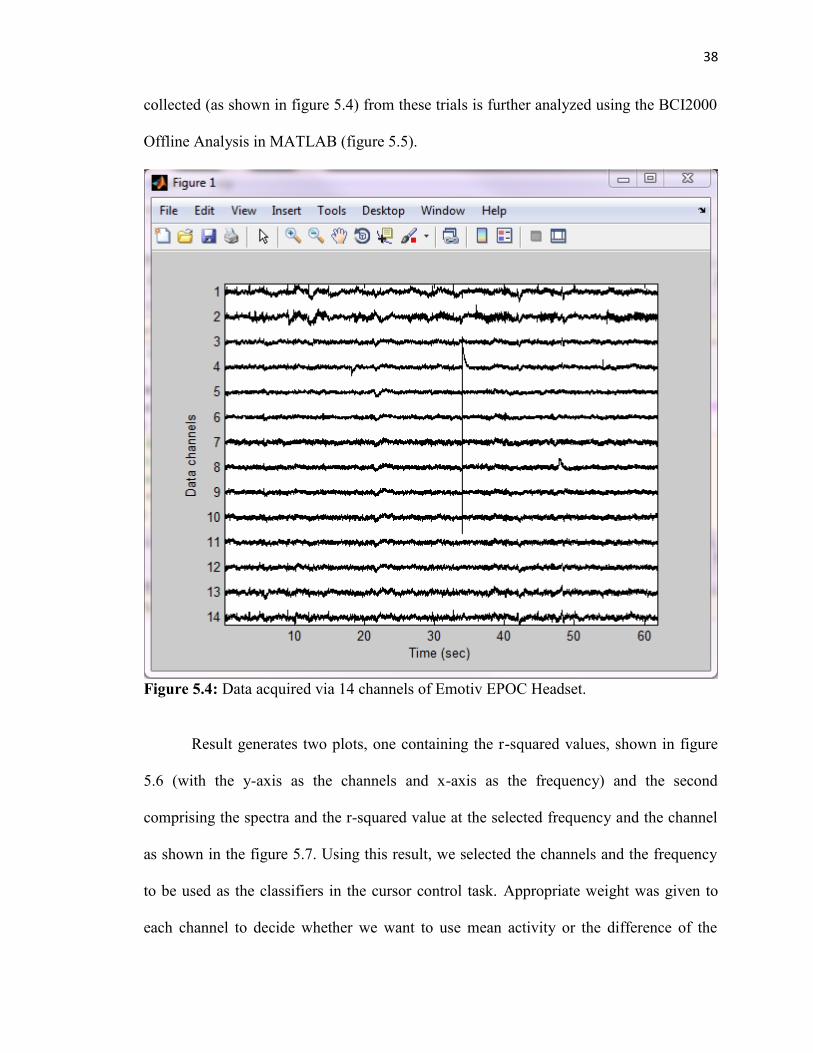
collected (as shown in figure 5.4) from these trials is further analyzed using the BCI2000
Offline Analysis in MATLAB (figure 5.5).
Figure 5.4: Data acquired via 14 channels of Emotiv EPOC Headset.
Result generates two plots, one containing the r-squared values, shown in figure
5.6 (with the y-axis as the channels and x-axis as the frequency) and the second
comprising the spectra and the r-squared value at the selected frequency and the channel
as shown in the figure 5.7. Using this result, we selected the channels and the frequency
to be used as the classifiers in the cursor control task. Appropriate weight was given to
each channel to decide whether we want to use mean activity or the difference of the
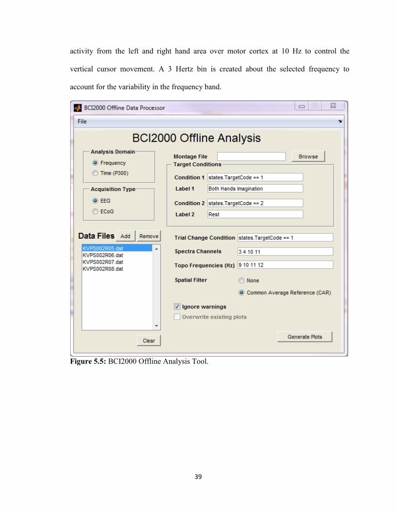
39
activity from the left and right hand area over motor cortex at 10 Hz to control the
vertical cursor movement. A 3 Hertz bin is created about the selected frequency to
account for the variability in the frequency band.
Figure 5.5: BCI2000 Offline Analysis Tool.

40
Figure 5.6: r-squared value between imagination and rest can be seen to be high (Red) atthe electrodes over the motor cortex and at around 10 Hertz frequency.
Figure 5.7: Spectra and the r-squared value at the selected channels. R-squared valueswere found to be significantly higher at 10 Hertz.

41
Apart from these two parameters there are other parameters like filtering. It plays
a critical role when it comes to feature extraction from the data. BCI2000 provides the
operator with a variety of filters to choose from; for e.g. Common Average Reference
(CAR), Large Laplacian, Small Laplacian etc. To find out the effect of each of those
filters and choose the one giving the best result programs, subroutines were written in
Matlab (refer to the Appendix A for the programs and subroutines). Using the results, it
was concluded that CAR filtering gives the better result than Laplacian filtering
techniques, as shown in figure 5.8.
Figure 5.8: Differences in the spectra output after using Laplacian (Top) and CAR(Bottom) filtering techniques. Both the images are result of data collected from sameelectrode and same parameters used to find the spectra except the filtering technique.

42
5.3 Biofeedback and Neuroplasticity
An immersive virtual environment (as shown in figure 5.9) was created by using Virtual
Reality Modeling Language (VRML) and V-Realm Builder 2.0 where every node of the
environment was individually controlled by the program written in Matlab (refer to
Appendix A). V-Realm Builder is a powerful three dimensional authoring package for
the creation of 3D objects and "worlds" to be viewed with V-Realm Browser or any other
VRML 2.0 compliant browser.
Figure 5.9: Virtual environment giving visual feedback of the hand opening and closingimagery task being performed.

43
Creating an interactive environment in the context of physical therapy increases
subject motivation and engagement, leading to active participation and learning by the
stroke survivor. This interactive feedback component of the system is also crucial to a)
distancing the subject from the challenges of the physical task, b) intuitively
communicating amplitude of error and direction for improvement and c) maintaining
subject engagement in repetitive task-oriented therapy. In the designed virtual world,
subject saw two hands which would open and close as the subject will perform the same
motor imagery task and will remain open when they are in resting state.
In order to control the objects of virtual environment, a User Datagram Protocol
(UDP) Communication was established between BCI2000 software and Matlab to
transfer the control states being collected by BCI2000 via Emotiv EPOC Headset. UDP is
within the Transmission Control Protocol/ Internet Protocol (TCP/IP) protocol suite that
is used in place of TCP when a reliable delivery is not required. There is less processing
of UDP packets than there is for TCP. UDP is widely used for streaming audio and video,
voice over IP (VoIP) and videoconferencing, because there is no time to retransmit
erroneous or dropped packets. Matlab program reading the server was written (refer to
Appendix A) to use two out of all the states being received by the program; TargetCode
and Signal(1,0). TargetCode values are the markers for the onset and offset of the targets
being given to the subject and Signal(1,0) values are the control values used to control the
cursor on the screen. In Signal state, 0, 1 and 2 referred to the direction of the cursor
movement on the screen. (0,0) is the 1D movement in X-direction (left to right on
screen), (1,0) is the 1D movement in Y-direction (top to bottom on screen) and (2,0) is
1D movement in Z-direction (in and out of the screen).

44
In the testing phase, this virtual environment can be controlled in two ways. We
can trigger the opening and closing of hand using the TargetCode value which is 0, when
none of the two targets are on the screen and is 1 and 2 with respect to the onset of each
of two target blocks. Therefore, when the value of TargetCode is 1, hands will start
opening and closing at the given frequency and will stop when the value reaches 2 or
reverts back to 0. Values collected from the Signal state can also be used to control the
hand in the virtual environment. Signal state values have got a range for each task which
varies for every subject; therefore, an average of the range collected from the training
phase has to be acquired. Using this has an advantage over using TargetCode. With this
the overall grip of the hands can be manipulated as per the incoming Signal value. If the
incoming value is close to the maximum value of the range, hands will grip fully making
a fist and if it is close to the minimum rather than making a full fist fingers will flex
slightly. Using this way, we are providing users with a feedback of their intensity of
imagery performance. Therefore, if the event related synchronization yields a very high
value of power then hands will grip completely, as shown in figure 5.10.
Virtual reality (VR) systems are novel and potentially useful technologies that
allow users to interact in three dimensions with a computer-generated scenario (a virtual
world). The implementation of conventional rehabilitation is resource-intensive and
costly, usually requiring transportation of patients and affecting adherence. Immersive
virtual environment with BCI system narrows down that gap and applies relevant
concepts in rehabilitation (i.e. repetition, intensity, and task-oriented training of the
paretic extremity) showing benefits in motor function improvement after stroke.
Neuroplasticity can be triggered in the clinical population suffering from impairment in

45
their central or peripheral nervous system as per Hebbian Type Learning [46]. The
general idea is an old one; that any two cells or systems of cells that are repeatedly active
at the same time will tend to become 'associated', so that activity in one facilitates activity
in the other. Therefore, the three modalities, Motor Imagery, Motor Observation and
Motor Execution (which excite the same part of the motor cortex) were combined to
generate the required rehabilitative effects.

46
CHAPTER 6
RESULTS AND CONCLUSIONS
Three out of five subjects, having no prior BCI experience were able to adapt to the
system in the given training phase with an increase in their performance with time. Being
a full time student, the remaining two did not completed all the training sessions and quit
due to sudden increase in their work; their performance was also showing improvements
like other three subjects but relatively slow. Detail of their performance is given in Table
6.1. Accuracy was determined using the following formula:
‘k’ represents the trial number in the testing session.
Table 6.1: Performance of healthy subjects in the cursor control task.# Subjects Total Sessions to Adapt Accuracy (post-
training)1. AXM 1 >85%2. KVP 1 >80%3. DIL 1 >90%4. UBS Excluded Excluded5. SXS Excluded Excluded
The result from healthy subjects was quite promising and opens up the possibility
of using BCI in rehabilitation in a cost effective manner. Combined with Assistive
Robotic and Virtual Reality, this system has the potential to provide rehabilitation to
stroke survivors. The Signal state which was intended to be used in the virtual
environment to open and close hand as per the power level of the motor imagery can also
be used for a robot. Therefore, the resultant would be assistive movement in

47
synchronization with the intention to move. Subjects having no residual movement can
imagine moving their impaired limb and the robot will move their limb on a pre-
programmed trajectory. This also satisfies the top-bottom approach of rehabilitation
where rather than using assistive therapy with little or no involvement of subject, system
waits for the effort to be put in by the patient. This approach calls for a high level of
subject involvement therefore can be called an active rehabilitation method rather than
passive one.
Further work can be done to analyze the efficacy of this setup as a rehabilitation
technique. Rather than testing it on healthy subjects, stroke patients who lost their ability
to move can be recruited and if their motor cortex is affected the contralateral side of
their motor cortex can be used to provide us with the motor imagery and rest state related
values to control a robot or objects in the virtual environment. The Emotiv EPOC headset
intended to be used as a gaming device by their originators, holds the capability to be
used in a BCI setup to control simple applications like cursor control in one and two
dimension. This is sufficient enough to acquaint the patients with their brain power to
heel themselves.

48
APPENDIX A
MATLAB PROGRAMS
Program 1: Function to implement Common Average Filtering
% This program is used to re-reference digitized EEG datato a common average reference (CAR)% Composed of 14 electrodes distributed over the entirescalp (i.e. electrodes of 10-20 system).% Channel data should be sent as an input% Channel Numbering Convention should be the one providedby Emotiv and BCI2000.% Only two electrode locations (i.e. F3 & F4) are re-referenced and returned.% Ref: "Spatial filter selection for EEG-basedcommunication", McFarland DJ, 1997% (C) Abhineet Mishra 2012-13% Graduate Student, NJITfunction [ret1, ret2] = epocCAR(data)
display('Applying Common Average Reference to C3 and C4');EEG_FC5 = data(4,:);EEG_FC6 = data(11,:);
% Channel Numbering is used as per the numbering used byWadsworth Center.% Channels used are AF3 F7 F3 FC5 T7 P7 O1 O2 P8 T8 FC6 F4F8 AF4ret1 = EEG_FC5 - ((1/14)*(data(1,:) + data(2,:) + data(3,:)+ data(4,:) + data(5,:) + data(6,:) + data(7,:) + data(8,:)+ data(9,:) + data(10,:) + data(11,:) + data(12,:) +data(13,:) + data(14,:)));
ret2 = EEG_FC6 - ((1/14)*(data(1,:) + data(2,:) + data(3,:)+ data(4,:) + data(5,:) + data(6,:) + data(7,:) + data(8,:)+ data(9,:) + data(10,:) + data(11,:) + data(12,:) +data(13,:) + data(14,:)));end

49
Program 2: Function to implement Laplacian Filtering
% This program is used to re-reference digitized EEG datato Laplacian Derivation (LARGE).% 64 or more channel data should be sent as an input% Channel Numbering Convention should be the one used byWadsworth Center.% Only two electrode locations (i.e. C3 & C4) are re-referenced and returned.% Ref: "Spatial filter selection for EEG-basedcommunication", McFarland DJ, 1997% (C) Abhineet Mishra 2012-13% Graduate Student, NJITfunction [ret1, ret2] = laplacian(data)
display('Applying Large Laplacian Derivation to Cp3 andCp4');EEG_Cp3 = data(16,:);EEG_Cp4 = data(20,:);% Electrodes used for re-referencing were F3 Cz P3 T7% 0.25 was calculated from the formula given in the paperMcFarland et al. 1997ret1 = EEG_Cp3 - (0.25 .* data(2,:) + 0.25 .* data(18,:) +0.25 .* data(57,:) + 0.25 .* data(45,:));
% Electrodes used for re-referencing were F4 Cz P4 T8ret2 = EEG_Cp4 - (0.25 .* data(6,:) + 0.25 .* data(18,:) +0.25 .* data(59,:) + 0.25 .* data(46,:));end

50
Program 3: Program to perform Offline Analysis on the collected EEG Data
% This program is to perform Offline Analysis on the EEGdata.% It imports the data file from the given path, filter itusing either% laplacian or CAR and calculated the Voltage spectra andr-square value% (C) Abhineet Mishra 2012-13% Graduate Student, NJIT% ------------------------------------------------------%% Importing Dataclcclear allimportdata('C:\Users\Abhineet\Desktop\Work\AXM001\AXMS001R14.ascii');EEG = ans.data;%% Spatial FilteringFs = 160; % Sampling Frequency of the EEG DataEEG = EEG';[EEG_c3, EEG_c4] = laplacian(EEG);%% Program to extract the trial from the data. Data isneeded to be loaded in the workspacej1=1;c1=1;j2=1;c2=1;TargetCode = EEG(71,:);
for i=1:length(EEG)if TargetCode(i) == 1
Lx1(j1,c1) = EEG_c4(1,i);c1 = c1 + 1;
else if TargetCode(i) == 2Rx1(j2,c2) = EEG_c4(1,i);c2 = c2 + 1;else if TargetCode(i) == 0 && (i-1 ~= 0)
if TargetCode(i-1) == 1j1 = j1+1;c1=1;
else if TargetCode(i-1) == 2j2 = j2+1;c2=1;
endend
end

51
endend
endclear c1 c2 j1 j2 i;
%% Finding Voltage and r2len1 = size(Lx1);len2 = size(Rx1);for i=1:len1(1)[PS1,f1] = pwelch(Lx1(i,:), triang(50),[ ],300,Fs);Vs1 = sqrt(10.^(PS1./10));X(1,:) = f1;Y(1,:) = f1;X(i+1,:) = Vs1;Y(i+1,:) = -1;end
for i=1:len2(1)[PS2,f2] = pwelch(Rx1(i,:), triang(50),[ ],300,Fs);Vs2 = sqrt(10.^(PS2./10));X(i+12,:) = Vs2;Y(i+12,:) = 1;End
%% Working on FINAL MATRIX X and Y STYLE 1for i=1:151c = cov(X(2:22,i),Y(2:22,i));varX = c(1,1);varY = c(2,2);covXY = c(1,2);r2(i) = covXY^2/varX*varY;endr2 = r2';hold onplot(f1,r2,'r')grid on

52
Program 4: Program to load the Virtual Environment designed in VRML using V-Realm
%% Hand.m is a script that loads handRAF.wrl that containsleft and% right hand articulated VRML models. It opens the objectand allows it% to be viewed in the default SL3D viewer.% R. Foulds 4/17/2013
% Open and view the object myhandmyhand = vrworld('handRAF.wrl');open(myhand);view(myhand);
% Rotate the right hand about the x and z axes to give aperspective viewmyhand.Handrot1.rotation=[0 1 0 -pi/4];myhand.Handrot2.rotation=[0 0 1 pi/4];
% Rotate left hand so it appears as mirror imagemyhand.LHandrot1.rotation=[0 1 0 -3*pi/4];myhand.LHandrot2.rotation=[0 0 1 pi/4];

53
Program 5: Function to interact with the Virtual Environment
%% bendvr.m is a function that cycles the fingers and%thumbs of the left and right hands of the VRML model from%fully extended (0 rad of each finger joint) to a flexion%angle that is between 0 and pi/2 rad, and back to 0 rad.
% R.Foulds 4/17/2013 edited by Abhineet Mishra to use itwith UDP Communication.
% The time for the cycling is determined by the secondpause value.
% The trajectory of flexion angles (an(i) is computed from0 to the maximum flexion angle, an(max))
% The maximum angle of flexion is determined by the current%value of the variable thinking. When thinking is negative,%it is set to 0. Otherwise the value of thinking (max of%1)is used to scale the flexion angle,%i.e. anmax=thinking*pi/2
% the increments in the trajectory are .1 rad scaled bythinking% i.e. .1*thinking
function bendvr(myhand,thinking)%% Check if thinking is less than 0if thinking<0
thinking=0;end
% Compute current flexion trajectoryan=0:0.1*thinking:pi/2*thinking;
%% Flex handsfor i=1:length(an)
%PM of right hand fingersmyhand.Indexbase2.rotation=[1 0 0 an(i)];myhand.Middlebase2.rotation=[1 0 0 an(i)];myhand.Ringbase2.rotation=[1 0 0 an(i)];myhand.Pinkybase2.rotation=[1 0 0 an(i)];
%PIP right hand fingersmyhand.IndexM.rotation=[1 0 0 an(i)];myhand.MiddleM.rotation=[1 0 0 an(i)];

54
myhand.RingM.rotation=[1 0 0 an(i)];myhand.PinkyM.rotation=[1 0 0 an(i)];
%DIP Right hand fingersmyhand.IndexD.rotation=[1 0 0 an(i)];myhand.MiddleD.rotation=[1 0 0 an(i)];myhand.RingD.rotation=[1 0 0 an(i)];myhand.PinkyD.rotation=[1 0 0 an(i)];
%MC Left hand fingersmyhand.LIndexbase2.rotation=[1 0 0 -an(i)];myhand.LMiddlebase2.rotation=[1 0 0 -an(i)];myhand.LRingbase2.rotation=[1 0 0 -an(i)];myhand.LPinkybase2.rotation=[1 0 0 -an(i)];
%PIP left handmyhand.LIndexM.rotation=[1 0 0 -an(i)];myhand.LMiddleM.rotation=[1 0 0 -an(i)];myhand.LRingM.rotation=[1 0 0 -an(i)];myhand.LPinkyM.rotation=[1 0 0 -an(i)];
%DIP left handmyhand.LIndexD.rotation=[1 0 0 -an(i)];myhand.LMiddleD.rotation=[1 0 0 -an(i)];myhand.LRingD.rotation=[1 0 0 -an(i)];myhand.LPinkyD.rotation=[1 0 0 -an(i)];
% pause(.005) %pause to allow thumb to move afterfinger flexion
myhand.Side1.rotation=[0 1 0 -an(i)];myhand.LSide1.rotation=[0 1 0 an(i)];
pause(.001) % Controls speed of flexionend
%% Extension (move back to 0 rad)% Follows reverse trajectory from an(max) to 0 radfor i=length(an):-1:1
% Right handmyhand.Indexbase2.rotation=[1 0 0 an(i)];myhand.Middlebase2.rotation=[1 0 0 an(i)];myhand.Ringbase2.rotation=[1 0 0 an(i)];myhand.Pinkybase2.rotation=[1 0 0 an(i)];
myhand.IndexM.rotation=[1 0 0 an(i)];myhand.MiddleM.rotation=[1 0 0 an(i)];

55
myhand.RingM.rotation=[1 0 0 an(i)];myhand.PinkyM.rotation=[1 0 0 an(i)];
myhand.IndexD.rotation=[1 0 0 an(i)];myhand.MiddleD.rotation=[1 0 0 an(i)];myhand.RingD.rotation=[1 0 0 an(i)];myhand.PinkyD.rotation=[1 0 0 an(i)];
% Left handmyhand.LIndexbase2.rotation=[1 0 0 -an(i)];myhand.LMiddlebase2.rotation=[1 0 0 -an(i)];myhand.LRingbase2.rotation=[1 0 0 -an(i)];myhand.LPinkybase2.rotation=[1 0 0 -an(i)];
myhand.LIndexM.rotation=[1 0 0 -an(i)];myhand.LMiddleM.rotation=[1 0 0 -an(i)];myhand.LRingM.rotation=[1 0 0 -an(i)];myhand.LPinkyM.rotation=[1 0 0 -an(i)];
myhand.LIndexD.rotation=[1 0 0 -an(i)];myhand.LMiddleD.rotation=[1 0 0 -an(i)];myhand.LRingD.rotation=[1 0 0 -an(i)];myhand.LPinkyD.rotation=[1 0 0 -an(i)];
% pause(.005)myhand.Side1.rotation=[0 1 0 -an(i)];myhand.LSide1.rotation=[0 1 0 an(i)];
pause(.001) %Controls speed of extensionend

56
Program 5: Function to read data from BCI2000 using UDP Communication
%% Program to read via UDP portip = 'localhost';port = 20320;% Create and open a UDP object that connects to BCI2000.u = udp( ip, 20319, 'LocalPort', port, 'Terminator','CR/LF', 'Timeout', 10 );fopen( u );
% Read data until timeout occurs.s = fgetl( u );
while( s~=-1 )disp(s)s = fgetl( u );
end
% Close and delete the UDP object.fclose( u );delete( u );

57
APPENDIX B
INSTITUTIONAL REVIEW BOARD APPROVAL LETTER

58
REFERENCES
1. Wolpaw J.R., Birbaumer N., McFarland D.J., Pfurtscheller G., Vaughan T.M., BrainComputer Interfaces for Communication and Control. Clinical Neurophysiology,2002, 113(6): 767-791.
2. Virani, Nathan D. Wong, Daniel Woo, Melanie B. Turner., Heart Disease and StrokeStatistics-2013 Update. American Heart Association, Dallas, Texas, 2013.
3. Murray C.J.L., Lopez A.D., The Global Burden of Disease: A ComprehensiveAssessment of Mortality and Disability from 1990 projected to 2000. HarvardUniversity Press, Cambridge, Massachusetts, 1996.
4. Nelles G. et al., Arm Training Induced Brain Plasticity in Stroke Studied with SerialPositron Emission Tomography. NeuroImage- Elsevier, 2001, 13(6): 1146–1154.
5. Liepert J. et al., Motor Cortex Plasticity during Constraint-Induced MovementTherapy in Stroke Patients. Neuroscience Letters, 1998, 250(1): 5-8.
6. National Institute of Neurological Disorders and Stroke, Interagency Head InjuryTask Force Report. Maryland: Bethesda, 1989.
7. Belda-Lois et al., Rehabilitation of Gait after Stroke: A Review towards a Top-DownApproach. Journal of NeuroEngineering and Rehabilitation, 2011, 8(66).
8. Dohring M.E., Daly J.J., Automatic Synchronization of Functional ElectricalStimulation and Robotic Assisted Treadmill Training. IEEE Transactions on NeuralSystems and Rehabilitation Engineering, 2008, 16: 310-313.
9. Fasoli S.E., Krebs H.I., Stein J., Frontera W.R., Hughes R., Hogan N., RoboticTherapy for Chronic Motor Impairments after Stroke: Follow-up Results. Archives ofPhysical Medicine and Rehabilitation, 2004, 85: 1106-1111.
10. Hidler J., Nichols D., Pelliccio M., Brady K., Advances in the Understanding andTreatment of Stroke Impairment using Robotic Devices. Topics in StrokeRehabilitation, 2005, 12: 22-35.
11. Edwards D.J., On the Understanding and Development of Modern PhysicalNeurorehabilitation Methods: Robotics and Non-Invasive Brain Stimulation. Journalof Neuroengineering and Rehabilitation, 2009, 6(3).

59
12. Mirelman A. et al., Effects of Robot-Virtual Reality Compared with Robot AloneTraining on Gait Kinetics of Individuals Post Stroke. Virtual Rehabilitation, 2007, 65-69.
13. Qiu Q., Adamovich S., Saleh S., Lafond I., Merians A.S., Fluet G.G., A Comparisonof Motor Adaptations to Robotically Facilitated Upper Extremity Task PracticeDemonstrated by Children with Cerebral Palsy and Adults with Stroke. IEEEInternational Conference of Rehabilitation Robot, 2011: 5975431.
14. Hand Randall, Virtual Worlds for Patient Rehabilitation. Vizworld Website. [Online]2010. http://www.vizworld.com/2010/03/virtual-worlds-patient-rehabilitation/
15. Jeannerod M., The Representing Brain: Neural Correlates of Motor Intention andImagery. Behavioral and Brain Sciences, 1994, 19: 187-245.
16. Gallese V. et al., Action Recognition in the Premotor Cortex. Brain, 1996,119(2):593-609.
17. Rizzolatti, Giacomo and Arbib, Michael A., Language within our grasp. Trends inNeurosciences, 1998, 21(5): 188-194.
18. Schilder P., The Image and Appearance of the Human Body. Routledge & KeganPaul, London, UK 1935.
19. Kosinski R. J., A Literature Review on Reaction Time. 1st ed., Clemson University,Clemson, South Carolina, 2008.
20. Kirschstein T., Köhling R., What is the Source of the EEG? Clinical EEG andNeuroscience, 2009, 40(3):146-149.
21. Ward J., The Student's Guide to Cognitive Neuroscience. 2nd ed., Psychology Press,New York, NY, 2010.
22. Hallez H., Vanrumste B., Grech R., Review on Solving the Forward Problem in EEGSource Analysis. Journal of Neuroengineering and Rehabilitation, 2007, 4: 4-46.
23. Chambers J. A., Saeid Sanei, EEG Signal Processing. 1st ed., Wiley-Interscience,New York, NY, 2007.

60
24. Fisch, Bruce. Fisch and Spehlmann's EEG Primer: Basic Principles of Digital andAnalog EEG. 3rd ed., Elsevier, Amsterdam, Netherlands, 1999.
25. Proverbio A., Alberto Z., The Cognitive Electrophysiology of Mind and Brain. 1sted., New York: Academic Press, 2002.
26. Olejniczak P., Neurophysiologic Basis of EEG. Journal of Clinical Neurophysiology,2006, 23(3): 186-189.
27. Kierkels M., Johannes J., Validating and Improving the Correction of OcularArtifacts in Electro-encephalography. Technische Universiteit Eindhoven,Netherlands, 2007.
28. Fraiwan L., Lweesy K., Khasawneh N., Wenz H., Dickhaus H., Automated SleepStage Identification System based on Time–Frequency Analysis of a Single EEGChannel and Random Forest Classifier. Computer Methods and Programs inBiomedicine, 2012, 108(1): 10-19.
29. Diego Rielo and Selim R. Benbadis, EEG Artifacts. [Online] April 2012.http://emedicine.medscape.com/article/1140247-overview#showall
30. Schalk G., McFarland D.J., Hinterberger T., Birbaumer N. and Wolpaw J.R.,BCI2000: A General-Purpose Brain-Computer Interface (BCI) system. IEEETransactions on Biomedical Engineering, 2004, 51(6): 1034-1043.
31. Blackwood D. H., Muir W. J., Cognitive Brain Potentials and their Application. TheBritish Journal of Psychiatry, 1990, 157(9): 96-101.
32. Peterson N.N., Schroeder C.E., Arezzo J.C. et. al., Neural Generators of EarlyCortical Somatosensory Evoked Potentials in the Awake Monkey.Electroencephalogrphy and Clinical Neurophysiology, 1995, 96(3): 248-260.
33. Pfurtscheller G. and Silva F.H., Event-related EEG/MEG Synchronization andDesynchronization: Basic Principles. Clinical Neurophysiology, 1999, 110(11):1842-1857.
34. Duvinage M. et al., A P300-Based Quantitative Comparison between the EmotivEPOC Headset and a Medical EEG Device. Proceedings of the IASTED InternationalConference Biomedical Engineering, ACTA Press, Austria, 2012.

61
35. Stamps K. and Hamam Y., Towards Inexpensive BCI Control for WheelchairNavigation in the Enabled Environment– A Hardware Survey. Brain Informatics,2010, 6334: 336-345.
36. NeuroAudience, Inc., NeuroAudience, Technology. [Online] 2011.http://astrid.astida.com/neuroaudience/technology.html
37. Beitas K. et al., Biological Measurements. University of Kardeljeva, Comlab.[Online] 2010. http://www.pef.uni-lj.si/eprolab/comlab/sttop/sttop-bm/bm-elephy.htm
38. Khushaba R.N. et al., Choice Modeling and the Brain: A Study on theElectroencephalogram (EEG) of Preferences. Expert Systems with Applications,2012, 39(16): 12378–12388.
39. Emotiv, Inc., Emotiv EEG- Quick Set up. Emotiv, Inc. [Online] 2013.http://www.emotiv.com/eeg/setup.php
40. McFarland D.J., Vaughan T.M. and Schalk G., The Wadsworth Center brain-computer interface (BCI) research and development program. Neural Systems andRehabilitation Engineering, 2003, 11(2): 1-4.
41. Christian J Bell et al., Control of a humanoid robot by a noninvasive brain computerinterface in humans. Journal of Neural Engineering, 2008, 5: 214.
42. Mason S.G. and Birch G.E., A General Framework for Brain–Computer InterfaceDesign. IEEE Transactions on Neural Systems and Rehabilitation Engineering, 2003,11(1): 70-85.
43. Mellinger J. and Schalk G., A Practical Guide to Brain-Computer Interfacing UsingBCI2000. Springer, New York, NY, 2009.
44. Wolpaw J.R. and McFarland D.J., Control of a two-dimensional movement signal bya noninvasive brain–computer interface in humans. Proceedings of the NationalAcademy of Sciences, Albany, NY, 2004, 101(51): 17849–17854.
45. Dewey R., [Online] 2011.http://www.intropsych.com/ch02_human_nervous_system/homunculus.html
46. Hebb D.O., The Organization of Behavior: A Neurophysiological Theory. New Ed.ed., Wiley & Sons, New York, NY, 1949.