copyright navistar corporation 2019 all rights reserved
TRANSCRIPT

Navistar Electrical Systems CV
Integration Guide - Jay E.
Bissontz [Digital Watermark]
Page 1 of 100 Revision Date: 06/01/2020
Navistar Electrical Systems CV Vocational Series Integration Guide
Copyright Navistar Corporation 2019 All Rights Reserved

Navistar Electrical Systems CV
Integration Guide
Page 2 of 100 Revision Date: 06/01/2020
Contents 1. Revision Summary Table ....................................................................................................................................... 3
2. Forward: .................................................................................................................................................................. 3
3. Vehicle Architectures:............................................................................................................................................ 6
3.1. Introduction: ................................................................................................................................................ 6 3.2. Multiplexing Architecture:............................................................................................................................. 6 3.2.1. High-Speed GMLAN ................................................................................................................................. 7 3.2.2. Chassis High-Speed GMLAN ................................................................................................................... 8 3.2.3. Powertrain High-Speed GMLAN ............................................................................................................... 8 3.2.4. Low-Speed GMLAN .................................................................................................................................. 8 3.2.5. Media Oriented Systems Transport (MOST) ............................................................................................. 8 3.2.6. Local Interconnect Network (LIN).............................................................................................................. 9 3.2.7. GateWay Modules .................................................................................................................................... 10 3.3. Data Link Connector (DLC) ......................................................................................................................... 10
4. Standard Electrical Offerings: ............................................................................................................................... 11
4.1. Typical Dash Layout: ................................................................................................................................... 11 4.2. Lights ON with Wipers: ................................................................................................................................ 12 4.3. Power Outlets .............................................................................................................................................. 12 4.4. Seat Belt Reminder Light ............................................................................................................................. 12
5. Power Take Off (PTO)............................................................................................................................................. 13
5.1. Power Take Off (PTO) & Engine Speed Controls (Sales Feature Code 12WGG) ........................................ 13 5.2. Power Take-Off (PTO) - Quick Start Reference ........................................................................................... 13 5.3. Factory PTO Settings .................................................................................................................................. 15 5.4. Primary PTO Operating Modes .................................................................................................................... 18 5.5. Preset PTO Operating Modes and Programming ......................................................................................... 19 5.5.1. Preset PTO - In-cab Operation: Enable Conditions [factory default programming] ................................... 19 5.5.2. Preset PTO - Remote Operation: Enable Conditions ................................................................................ 20 5.5.3. Preset PTO - Remote Operation with In-Cab Engage: Enable Conditions ................................................ 21 5.6. Variable PTO Operating Modes and Programming ...................................................................................... 22 5.6.1. Variable PTO - In-cab operation: Enable Conditions ................................................................................. 22 5.6.2. Variable PTO - Remote Operation: Enable Conditions.............................................................................. 22 5.6.3. Variable PTO - Remote Operation with In-Cab Engage: Enable conditions .............................................. 23 5.7. Diesel Particulate Filter [DPF] Cleaning during Stationary PTO Operation ................................................... 25 5.8. Mobile PTO Operating Modes and Programming ........................................................................................ 26 5.8.1. Mobile PTO - in-cab operation only: Enable Conditions ............................................................................ 26 5.9. OSIM PTO (Operator Selectable In-Cab Mode) ........................................................................................... 27 5.9.1. OSIM PTO - Preset [Stationary] Operation: Enable Conditions ................................................................. 27 5.9.2. OSIM PTO - Variable [Stationary] Operation: Enable Conditions ............................................................. 27 5.9.3. OSIM PTO - Mobile Operation: Enable Conditions .................................................................................. 27 5.10. PTO System Disengage Conditions ........................................................................................................... 28 5.10.1. Stationary Modes [preset or variable] - in-cab control ............................................................................. 28 5.10.2. Stationary Modes [preset or variable] - remote control [with or without in-cab engage] ........................... 29 5.10.3. Mobile Mode ........................................................................................................................................... 30 5.11. Prolonged or Extended PTO Operation ..................................................................................................... 31 5.11.1. Diesel Particulate Filter [DPF] Cleaning during Stationary PTO Operation .............................................. 31 5.12. PTO Operational Speed Control ................................................................................................................ 32 5.12.1. [Variable] PTO operational speed control provides the following functions: ............................................. 32 5.12.2. In-cab Cruise Res + Switch (or Remote PTO Tap Up switch) ................................................................. 32 5.13. Driver Information Center (DIC) Warnings Messages ................................................................................ 36 5.14. Appendix: PTO, Remote Engine Speed Control, and General Safety Recommendations .......................... 37
6. Fast Idle Control – Engine Speed Control L/PTO ................................................................................................. 42
6.1. To obtain Fast Idle capability you must order the following options: ............................................................. 42 Required Initial Conditions .................................................................................................................................. 42 6.2. Enable (Turn ON) Fast Idle .......................................................................................................................... 43 6.3. Preset Fast Idle ........................................................................................................................................... 43 6.4. Adding Fast Idle (UF3) ................................................................................................................................ 43
7. Truck Equipment Manufacture (TEM) Options ..................................................................................................... 44
7.1. Auxiliary Switches / Relay outputs: .............................................................................................................. 44 7.1.1. International Factory Feature 08XJP – Switch, Auxiliary, 4 Switches with 30-Amp fuses (Same as GM
feature RPO 9L7) ............................................................................................................................... 44 7.1.2. International Factory Feature 08XLS – Switch, Auxiliary, 6 Switches with 20-Amp fuses, Accessory
Controlled, with Switches in Headliner (Same as GM feature RPO UEH) ........................................... 50 7.1.3. International Factory Feature 08XJG – Fog Lights, Halogen Rectangular (Same as GM feature RPO T3U) 53 7.1.4. International Factory Feature 08WTT – Auxiliary Switch for Worklight (Same as GM feature RPO UEH).. 54 7.1.5. International Factory Feature 08XKS – Auxiliary Switch for Roof Beacon/Worklight (Same as GM feature
RPO TRW) ......................................................................................................................................... 55

Navistar Electrical Systems CV
Integration Guide
Page 3 of 100 Revision Date: 06/01/2020
7.2. Body Builder Wiring and Harness ................................................................................................................ 57 7.2.1. International Factory Feature 08TUM – Auxiliary Harness – Y-Harness for Plow Applications (Same as GM
feature RPO UNL) .............................................................................................................................. 57 7.2.2. Body Builder Wiring – Factory Feature 08HXV – Back of Cab (Same as GM feature RPO 5DX) .............. 58 7.2.3. Body Builder Wiring – Factory Feature 08HXU – Rear of Frame (Same as GM feature RPO 5DY) .......... 60 7.3. Stop, Turn, Tail-lights and Wiring ................................................................................................................. 62 7.3.1. Stop, Turn, Tail-lights – Factory Feature 08TUL (Same as GM feature RPO TR1) ................................... 62 7.3.2. Stop, Turn, Tail Lights – Factory Feature 08TUK (Same as GM feature RPO UGE) ................................. 63 7.3.3. Stop, Turn, Tail-lights – Factory Feature 08TKD ....................................................................................... 64 7.3.4. Tail Light Wiring Modified – Factory Feature 08NAA ................................................................................. 64 7.4. Trailer Connections and Controls ................................................................................................................ 65 7.4.1. Trailer Connection Socket – Factory Feature 08TRA (Same as GM feature RPO UY7) ............................ 65 7.4.2. Trailer Brake Control, Integrated – Factory Feature 08HBW (Same as GM feature RPO JL1) .................. 67 7.5. Back-Up Alarm Electric 102 dBa – Factory Feature 08THB (Same as GM feature RPO UZF) ..................... 68 7.6. Power Inverter – Factory Feature 08XJX - (Same as GM feature RPO KI4) ................................................ 69
8. Auxiliary Battery Connections .............................................................................................................................. 69
8.1. Repair/Recommendation: ............................................................................................................................ 70 8.2. Additional Information: ................................................................................................................................. 70 8.2.1. Positive Cable Recommendation. ............................................................................................................. 70 8.3. Jump Start Stud - Factory Feature 08WBW - (Same as GM feature RPO BTN) .......................................... 73
9. Rearview Camera Installation ................................................................................................................................ 74
9.1. Mounting the Camera .................................................................................................................................. 74 9.2. Camera Installation Guidelines .................................................................................................................... 74 9.3. Camera System, Rear View – Factory Feature 08RNY – (Same as GM feature UVC) ................................ 76
10. Infor – Radio Telephone/Mobile radio (Transceiver) Installation and troubleshooting Guidelines ................. 77
10.1. Transceiver Location ................................................................................................................................. 78 10.2. Antenna Installation ................................................................................................................................... 78 10.3. Antenna Cable Routing.............................................................................................................................. 79 10.4. Antenna Tuning ......................................................................................................................................... 79 10.5. Radio Wiring and Connection Locations .................................................................................................... 79 10.6. Radio Wire Routing ................................................................................................................................... 80 10.7. Troubleshooting ......................................................................................................................................... 80
11. Gauge and Fault Code Display ............................................................................................................................ 83
11.1. Base Gauge Cluster: ................................................................................................................................. 83 11.2. Premium Gauge Cluster: ........................................................................................................................... 84
12. Relocation of electrical Components/Devices-Best Practices/Recommendations .......................................... 84
12.1. Under-hood/Vehicle: .................................................................................................................................. 84 12.2. Under-dash: .............................................................................................................................................. 85 12.3. Doors: ....................................................................................................................................................... 85 12.4. Under Seats: ............................................................................................................................................. 85 12.5. Rear Stowage Areas: ................................................................................................................................ 85 12.6. General Recommendation: ........................................................................................................................ 85
13. Appendix - General Electrical Section: ............................................................................................................... 85
13.1. Color Code System for International® Truck Wiring: .................................................................................. 86 13.2. Recommended Circuit Protection: ............................................................................................................. 86 13.3. Electrical Components Commonly Used by Equipment Installers: ............................................................. 87 13.4. Wire Splicing and Termination - Standard Terminals and Splices: ............................................................. 88 13.5. HIGH VOLTAGE CIRCUITS (GREATER THAN 50 VOLTS) ON INTERNATIONAL TRUCKS AND BUSES: 95
1. Revision Summary Table
REVISION DATE SECTION CHANGE DESCRIPTION REASON FOR CHANGE REVISED BY
01 9/12/2019 ALL INITIAL DRAFT INITIATION OF DOCUMENT
J. BISSONTZ
02 5/29/2020 ALL ADDED CONTENT UPDATE L LEON
2. Forward:

Navistar Electrical Systems CV
Integration Guide
Page 4 of 100 Revision Date: 06/01/2020
Warning - In the pages of this document are a diverse set of truck chassis system and subsystem integration features which contain the potential for both simple and complex operational situations and interactions when integrated in combination with a truck chassis and truck mounted equipment. It is the responsibility of persons performing truck chassis and, or truck mounted equipment system integration and testing to fully understand the plurality of operational outcomes and take the appropriate as well as necessary precautions to avoid property damage, personal injury up to and including death when performing system integration and, or test in association with the content of this document. Note - In this manual, International® Truck and Engine Corporation provides information about its different products to assist those who wish to modify these products for individual applications. International does not recommend or approve any firm nor make any judgements on the quality of the work performed by a particular firm. Individuals who use the services of a Body Builder must satisfy themselves as to the quality of the work. The party installing a body, a fifth wheel, any other equipment, or making any modifications to complete the vehicle for delivery and make it road-ready is responsible to see that the completed vehicle complies with all applicable certification procedures and safety standards, as may be set forth in Federal, State, and local statutes, rules and regulations. Specifications, descriptions and illustrative material in this literature are as accurate as known at time of publication but are subject to change without notice. Illustrations are not always to scale and may include optional equipment and accessories but may not include all standard equipment. Safety Information: IMPORTANT - Read the following before starting the service procedure. You must follow your company safety procedures when you service or repair equipment. Be sure to understand all procedures and instructions before you begin work on the unit. Some procedures require the use of special tools for safe and correct service. Failure to use these special tools when required can cause injury to service personnel or damage to vehicle components. DISCLAIMER: INTERNATIONAL DOES NOT TAKE ANY RESPONSIBILITY FOR CUSTOMER OR BODY BUILDER WIRING. NOTE - After-market installed wiring for engine speed control must comply with the following guidelines: 1. Sealed switches and connectors must be used for switches and connections that are exposed to the weather or to salt spray emanating from the vehicle's tires. 2. Route and clip wiring to minimize chafing and exposure to weather. Use conduit, loom, and/or tape to achieve this.

Navistar Electrical Systems CV
Integration Guide
Page 5 of 100 Revision Date: 06/01/2020
3. Fuse all power leads as close to the power source as possible. Remember fuses protect the wiring - size fuses accordingly. 4. All ground connections that will be made to the frame or body must be connected to clean bare metal. Remove all dirt, paint, grease and rust that would insulate the terminal from ground. After connecting the ground, seal the connection with a good quality grease or surface sealant to protect the connection from corrosion. 5. Spliced wires should be twisted together and soldered. Use a heat shrink tube with a meltable inner wall to seal the connection. Do not expose splices to the weather. WARNING - To avoid serious personal injury, possible death, or damage to the vehicle, make sure the transmission is in neutral, parking brake is set, and the wheels are blocked before undertaking service procedures. In addition, turn off the engine when you leave the vehicle. Never leave the vehicle unattended with the engine running. WARNING - To avoid personal injury, possible death, or damage to the vehicle when adding electrical features, disconnect batteries. Reconnect batteries when installation is complete. Whenever disconnecting battery terminals; always disconnect the ground terminal first. When reconnecting, always connect the ground terminal last. To prevent injury to the eyes, face, limbs and body, it is imperative that lighted materials, flames or sparks be kept away from the vent openings of the battery. The gas mixture in the battery cells, which escapes through the vents, could ignite and/or cause an explosion. This is particularly true when jumper cables are being used. In addition, inhaling of gas produced by the normal operation of the battery could result in partial or permanent damage to the respiratory system. Always wear eye protection when working around batteries. Do not attempt to jump-start a vehicle having a frozen battery because the battery may explode. If a frozen battery is suspected, examine all fill vents on the battery. If ice can be seen, do not attempt to start with jumper cables as long as the battery remains frozen. Thaw out the battery and recharge. Do not check battery condition by shorting (flashing) across terminals. Failure to observe these instructions could result in personal injury and/or damage to the vehicle. Battery cable terminals must be clean and tight. Use hot water and common baking soda for removing terminal corrosion and for cleaning the top of the battery. Brighten the contact surface with steel wool, apply a light coat of lubricant sealing grease such as Fleetrite ® 472141-C1 or equivalent and reassemble. Be sure the terminals are clamped tightly and that the battery is clamped securely in place. When working around the terminals and battery, use extra care to avoid shorting. A good practice is to insulate pliers and screwdrivers.

Navistar Electrical Systems CV
Integration Guide
Page 6 of 100 Revision Date: 06/01/2020
3. Vehicle Architectures:
3.1. Introduction: Unlike the electrical systems on previous models, which utilized point-to-point wiring for all input signals and output loads, this system uses multiplex technology to provide control and communication between major functional areas of the vehicle. Multiplexing simply means, communicating multiple pieces of information via a single twisted pair of wires (called the data link) without requiring a wire for each piece of information. This information could be gauge information such as engine oil pressure, or switch information that controls vehicle functions such as headlamps. The electrical system relies on a collection of electronic circuit modules and software to perform vehicle functions instead of implementing similar features using complex wire harness designs with electromechanical relays and switches. These electronic module components are connected together by data links. The data links can be thought of as computer networks that allow the electronic components on the vehicle to communicate with one another. The concept of multiplexing is not new since data links for communicating between engine controllers, the instrument cluster and the diagnostic connector have been used for several years. The goal of multiplexing is to reduce cab harness wiring and to simplify circuits. This is accomplished by using a low current data link for communicating between cab switches, the Body Controller and the Instrument Cluster. Other data links in the vehicle allow other electrical controllers, the BC and the Instrument Cluster to communicate with each other.
3.2. Multiplexing Architecture: The International® CV™ utilizes a variety of communication buses to ensure a timely and efficient exchange of information between devices. There are six different communication buses on the International® CV™
• High-Speed GMLAN
• Chassis High-Speed GMLAN
• Powertrain High-Speed GMLAN
• Low-Speed GMLAN
• Media Oriented Systems Transport (MOST)
• Local Interconnect Network (LIN)

Navistar Electrical Systems CV
Integration Guide
Page 7 of 100 Revision Date: 06/01/2020
Figure 3.2.1 GM LAN NETWORKS
3.2.1. High-Speed GMLAN The High-Speed GMLAN Bus is used where data needs to be exchanged at a high enough rate to minimize the delay between the occurrence of a change in sensor value and the reception of this information. The High-Speed GMLAN serial data network consists of two twisted wires, known as a twisted pair. One signal circuit is identified as GMLAN-High and the other signal circuit is identified as GMLAN-Low. At each end of the data bus there is a 120ohm terminating resistor between the GMLAN-High and GMLAN-Low-circuits. Shown in figure 3.2.1 as red trace line Terminating resistors are used in vehicle data buses to prevent signal reflections caused by the impedance of an individual circuit. These signal reflections can generate false signals which alter the data being transmitted across the network. Terminating resistors add a load to the circuits, allowing higher data transmission rates. This is achieved by returning both the high and low signal circuits to their resting state within fractions of a second. Data symbols, (1’s and 0’s), are transmitted sequentially at a rate of 500 kilobits-per-second. The data being transmitted over the bus is represented by the voltage difference between the GMLAN High and the GMLAN-Low signal circuit voltage. When the two-wire bus is at rest, meaning there is no data being transmitted, the GMLAN-High and GMLAN-Low signal circuits are not being driven. In this state, both signal circuits are approximately 2.5 volts. The differential voltage between the two is around zero volts. Differential voltage in data communication is used to describe the difference in voltage between two signal circuits of a data bus. When data is being transmitted, the GMLAN-High signal circuit is driven higher to about 3.5 volts and the GMLAN-Low signal circuit is driven lower to about one-point-five volts. The differential voltage becomes approximately 1.5 volts with a variance of +/- 0.5v.

Navistar Electrical Systems CV
Integration Guide
Page 8 of 100 Revision Date: 06/01/2020
3.2.2. Chassis High-Speed GMLAN The Chassis High-Speed GMLAN or GMLAN Chassis Expansion Bus operates same as the High-Speed GMLAN bus, except that it is reserved for chassis components. Shown in figure 3.2.1 as orange trace line. This split is designed to reduce message congestion between the buses and to ensure timely message transmission and reception. Communication is often required between the GMLAN Chassis Expansion Bus and the primary High Speed GMLAN Bus. This is accomplished through the vehicle's gateway module. 3.2.3. Powertrain High-Speed GMLAN The GMLAN Powertrain Expansion Bus operates similar to the High-Speed GMLAN Bus, however it is reserved for powertrain components. The bus is optional based on how the vehicle is equipped. Shown in figure 3.2.1 as green trace line. Communication between the GMLAN Powertrain Expansion Bus and the primary High-Speed GMLAN Bus is accomplished by using the Engine Control Module, or ECM, as the gateway module. The high-speed GMLAN Chassis Expansion Bus, the High-Speed GMLAN Powertrain Expansion Bus, and primary High-Speed GMLAN Bus all operate in the same manner, therefore the diagnostics for each are similar.
3.2.4. Low-Speed GMLAN The Low-Speed GMLAN Bus is used in applications where a high baud rate is not required. It is typically used for operator-controlled functions where the response time requirements are slower than those needed for dynamic vehicle control. Shown in figure 3.2.1 as purple trace line. The Low-Speed GMLAN serial data network bus utilizes a single wire, and is ground referenced with a high-side voltage drive. During vehicle operation, data symbols, (1’s and 0’s) are transmitted sequentially at the normal rate of 33.3 kbit/s. For component programming only, a special high-speed data mode of 83.3 kilobit/s may be utilized. Unlike the high-speed dual wire networks, this single wire low speed network does not use terminating resistors at either end of network. The data symbols transmitted over the bus are represented by different voltage signals. When the low-speed GMLAN bus is at rest, there is a low signal voltage of approximately 0.2v. When data is transmitted, the signal voltage is driven higher to around 4.0v or higher.
3.2.5. Media Oriented Systems Transport (MOST) The Media Oriented Systems Transport, or MOST [most], infotainment network is a dedicated, high-speed, multimedia streaming data bus independent from the GMLAN data buses. Shown in figure 3.2.1 as yellow trace line. The MOST bus is configured in a physical hardwired loop, or ring, with each device on the bus transmitting and receiving data on their assigned address in a set order.

Navistar Electrical Systems CV
Integration Guide
Page 9 of 100 Revision Date: 06/01/2020
This type of bus utilizes a master-slave relationship between devices, with the MOST master-device acting as a central hub for the MOST node devices. The radio module (A11) is the MOST Master devise and will monitor the bus for vehicle configuration. In the event of a fault to the radio a slave node will be used as a surrogate MOST master. Each device on the MOST bus is connected by twisted pair cooper wires (2 transmit (TX), 2 receive (RX), and one electronic control line which is a 12V wakeup signal circuit. Figure 3.2.2 MOST wiring diagram
During initialization, the MOST master device sends a short 100 millisecond low voltage wakeup pulse on the electronic control circuit. All connected devices on the MOST bus will receive this wakeup pulse. Once this wakeup signal is received by the node devices, each device responds to the MOST master device with their specific device address and supported functionality. The MOST Bus Diagnostic Tool Kit", tool number: EL- 51578, can be used to bypass potentially faulted devices on the bus, narrowing down the cause of the bus fault.
3.2.6. Local Interconnect Network (LIN)
The Local Interconnect Network, or LIN, bus is used to exchange information between a master control module and other smart devices which provide supporting functionality. Figure 3.2.3 Example of LIN

Navistar Electrical Systems CV
Integration Guide
Page 10 of 100 Revision Date: 06/01/2020
The LIN bus consists of a single wire with a transmission rate of 10.417 kbit/s. This type of configuration does not require the capacity or speed of either the High-Speed GMLAN bus or the Low Speed GMLAN bus. Data symbols (1’s and 0’s) transmitted over the LIN bus are represented by different voltage levels. When the LIN bus is at rest, the signal is in a high voltage state, approximately Vbatt, or equal to battery voltage. When data is transmitted, the signal voltage is driven low, around zero volts. 3.2.7. GateWay Modules The majority of information that exists within a given network generally stays local; however, some information must be shared across networks. Control modules designated as a gateway will transfer information between various buses. A gateway module is connected to at least two buses and will interact with each network according to its message strategy and transmission models. There are four different gateway modules that interlink the networks of the International CV. In the event of a module failure, a non-gateway module may act like a gateway module to maintain communications between critical systems. The radio module acts as a gateway between the MOST bus, the LIN bus, and the Low-Speed GMLAN Bus networks. The ECM acts as a gateway between the High-Speed GMLAN bus and the Powertrain Expansion GMLAN bus. The Serial Data Gateway Module, or SDGM, is a dedicated gateway module, and enables cross communication between the High-Speed GMLAN bus, the chassis high-speed GMLAN bus, and the low speed GMLAN bus. The Body Control Module, or BCM, acts as a gateway between the low-speed GMLAN bus, the high speed GMLAN bus, and the LIN bus. 3.3. Data Link Connector (DLC) The X84 Data Link Connector (DLC) is a standardized 16-cavity connector. The connector conforms to J1962 standard for hardware interfaces
Figure 3.2.3 Example of LIN

Navistar Electrical Systems CV
Integration Guide
Page 11 of 100 Revision Date: 06/01/2020
4. Standard Electrical Offerings:
4.1. Typical Dash Layout: Below is shown a typical dash layout with components identified. Please not some components show are not standard. Figure 4.1.1: Instrument Panel Layout
Table 4.1.2: Instrument Panel Layout
Component Locations and Descriptions
(1) Trailer Brake Control Switch (9) Accessory Power Receptacle – 110V AC (KI4)
(2) Speaker – Left Instrument Panel (UQ3) (10) Accessory Power Receptacle – Instrument Panel 2
(3) Instrument Cluster (11) Accessory Power Receptacle – Instrument Panel 1
(4) Ambient Light/Sunload Sensor (12) USB Receptacle
(5) Info Display Module (13) Seat Heating and Cooling Switch – Driver
(6) Seat Heating and Cooling Switch – Passenger
(14) Data Link Connector
(7) Speaker – Right Instrument Panel (UQ3)
(15) Headlamp Switch
(8) Switches –PTO switch location (16) Transfer Case Shift Control Switch

Navistar Electrical Systems CV
Integration Guide
Page 12 of 100 Revision Date: 06/01/2020
4.2. Lights ON with Wipers: Standard Factory feature. If the windshield wipers are activated in daylight with the engine ON, and the exterior lamp control is in the AUTO position, the headlights, parking lights and other exterior lamps come ON. The transition time for the lamps coming on varies based in wiper speed. When the wipers are not operating these lamps turn OFF. To disable this feature, move the exterior lamp to or 4.3. Power Outlets 12 Volt Key Hot and Battery Hot are available in the center stack and console. There may be up to 4 power outlets. The power outlets on the center stack and in front of the cupholders are powered at all times. The power outlets inside the storage area and in the rear of the console are powered when the ignition is ON or in ACC or when Retained Accessory Power (RAP) is active.
4.4. Seat Belt Reminder Light
There is a seat belt reminder light on the gauge cluster. When the vehicle is started, this light will flash and a chime may come ON to remind the operator to fasten their seat belt. The light will stay ON solid until the belt is buckled. The cycle will continue if driver remains or becomes unbuckled.

Navistar Electrical Systems CV
Integration Guide
Page 13 of 100 Revision Date: 06/01/2020
5. Power Take Off (PTO)
5.1. Power Take Off (PTO) & Engine Speed Controls (Sales Feature Code 12WGG)
Factory installed optional feature provides engine speed control for electronically controlled Power Take Off (PTO) device, includes ON/OFF switch mounted on Dash, with steering wheel mounted engine speed control button. PTO feature must be ordered with correct transmission. Figure 5.1.1: PTO Dash Mounted Switch
Figure 5.1.2: Steering Wheel Mounted Controls
This feature cannot be added to unit after production.
5.2. Power Take-Off (PTO) - Quick Start Reference
The PTO is a Truck Equipment Manufacture (TEM) integrated system that allows the user to create an auxiliary power source for running add-on equipment, such as salt spreaders, dump beds, lifts, winches, and lift buckets etc. The PTO system controls engine speed to values higher than normal base idle, PTO load relay engagement, and remote starting and shutdown of the engine.

Navistar Electrical Systems CV
Integration Guide
Page 14 of 100 Revision Date: 06/01/2020
When the operator requests PTO using either the PTO switch or PTO remote, the engine control module (ECM) converts the data from the engine speed sensor to a 2 pulse/engine revolution signal. When PTO is engaged, the power take-off module (PTOM) sends a GMLAN serial data message to the ECM requesting engine speed, in response to signals from the PTO switch or remote.
PTO Components
The OEM PTO components consist of:
• The transmission [internal] PTO gear – rotates with the torque converter
• The in-cab PTO switch and cruise control SET and RES switches
• The PTO telltale indicator
• The Driver Information Center (DIC)
• The Radio and Navigation Screen (HMI)
• The Power Take Off Module (PTOM)
• The remote PTO Truck Equipment Manufacture (TEM) connector [X191]
Note: The interface connector [X191] is located at the rear of the cab near the RH frame
rail and comes with a cap which is the mating half to the truck harness connector. This is
the connector the Truck Equipment Manufacture (TEM) will use to wire in external
electrical components such as a control relay, oil solenoid [these two are basic to all
systems] and possibly external switches to control the PTO from outside the cab.
Figure 5.2.1: PTOM Mounting Location

Navistar Electrical Systems CV
Integration Guide
Page 15 of 100 Revision Date: 06/01/2020
Figure 5.2.2: X191 Engine Harness to Power Take-Off Jumper Harness
Figure 5.2.3: X191 PTOM Connector Circuit Information
5.3. Factory PTO Settings The PTO system is programmed in the plant for a basic 3 speed idle up [Stationary Preset] mode with the relay control circuit enabled and ready to close a control relay. [The relay is not included and must be added by the Truck Equipment Manufacture (TEM).] For most customers the only electrical connections that are required are a control relay and an oil solenoid. The system is ready to go. [Older systems did not have the relay driver turned on so they would not engage the PTO until reprogrammed at a dealer. That has been corrected.]
The three factory speeds are: 1. 900 RPM – occurs with press and release of the PTO switch 2. 1200 RPM – occurs with press and release of the Cruise SET switch [if PTO is
ON]

Navistar Electrical Systems CV
Integration Guide
Page 16 of 100 Revision Date: 06/01/2020
3. 1900 RPM – occurs with press and release of the Cruise Resume Switch [if PTO is ON]
See schematic below. The components in the grey dashed shaded box are what must be connected to X191 for basic in cab operation [Stationary Preset]. IMPORTANT: On a new unit before anything is connected, start the truck in park with the park brake set and the Cruise Control Switch is OFF. Press and release the PTO in-cab Switch. You should be able to achieve the 3-speed operation described above. If not, have the dealer fix it before you proceed! When proper idle up operation is confirmed THEN connect your components.
Figure 5.3.1: Schematic for basic ‘IN-CAB’ PTO operation using control relay and oil solenoid as well as
optional outside ‘remote’ operation [start/stop, tap up/down]
NOTE: The PTO connector X191 has a cap installed at the assembly plant with a jumper between pins A and J. The cap is a useable mating connector and it could be rewired as shown above. To avoid setting internal trouble codes the continuity between connector cavities A and J must be constantly maintained except during kill switch actuation for MY2015-17. MY2018 and beyond the jumper is only required for remote operation if arm and kill switches are not configured.

Navistar Electrical Systems CV
Integration Guide
Page 17 of 100 Revision Date: 06/01/2020
Figure 5.3.2: Full System Schematic [shows with all possible external connections]
NOTES:
1. Cavity N control signal must be implemented with a switch OR a potentiometer,
not both.
2. For MY2015-17 continuity between pins A & J is monitored, must be
maintained. It can be interrupted only during the actuation of the kill switch.
Continuous loss of continuity between pins A and J will result in setting system
trouble codes.
3. For MY2018 and beyond the A to J jumper is not required except for remote
modes where the ‘arm’ and ‘kill’ switches are not configured.

Navistar Electrical Systems CV
Integration Guide
Page 18 of 100 Revision Date: 06/01/2020
5.4. Primary PTO Operating Modes PTO modes of operation include the following:
• Preset [Stationary] In-cab control standard. Remote control available. In cab engage with remote control available
• Variable [Stationary]
• In-cab control standard. Remote control available. In cab engage with remote control
• Mobile In-cab control only
• OSIM (Operator Selectable In-Cab Mode) [Stationary or Mobile] requires pairing of modes. Then unit can operate within the paired modes.
Notes:
• Factory default programming enables in-cab controls.
• A Navistar CV vehicle service tool can reprogram the system to allow for remote control. In-cab controls can be left active [in-cab engage with remote control] or disabled. OSIM can be enabled for dual stationary/mobile mode pairing.
• All PTO modes provide for engine rpm control and PTO load relay control [engage/disengage].
• All PTO modes provide for safety interlocks for PTO load disengagement.
• Remote PTO modes provide for both in-cab and remote engine starting, and shutdown. Emergency vehicle provisions for PTO are not compatible with remote mode.
• All Stationary PTO modes provide for engine shutdown due to critical engine conditions, as well as a timed engine shutdown feature. However, when ordering any Navistar Emergency Vehicle vocational sales applications, Automatic Engine Shutdown is disabled.
• For the remote pendant applications, the ‘Remote Pendant Enable Switch’ must be in the open position when connecting or disconnecting the pendant cable.
• Emergency Vehicle provisions for PTO are limited to the disabling the following Automatic Engine Shutdown conditions
a) Low Fuel b) Engine Coolant Hot c) Transmission Fluid Hot d) Low Engine Oil e) Low Engine Oil Pressure f) Diesel Particulate Filter Regeneration Warning
Note: Engine shutdown, based on critical engine or PTO system fault conditions could be disabled using the service tool for non-emergency application. “PTO Engine Shutdown” Parameter needs to be programmed to “Disable” using service tool.

Navistar Electrical Systems CV
Integration Guide
Page 19 of 100 Revision Date: 06/01/2020
5.5. Preset PTO Operating Modes and Programming
5.5.1. Preset PTO - In-cab Operation: Enable Conditions [factory default programming]
To Enable PTO the following conditions must be satisfied: 1. Engine must be running. 2. The vehicle cannot be moving. 3. The parking brake must be set. 4. The shift lever must be in PARK [P]. 5. The brake pedal must not be depressed. 6. Cruise Control must be OFF. 7. Press and release the PTO In-cab switch, located below the center console.
The PTO telltale will blink rapidly until the PTO load relay becomes engaged (Ref. Note 3 below). The telltale will then be steady. The engine will advance to the PTO Standby speed.
8. After PTO Standby speed is achieved the Cruise Control SET- and RES+ switches can be used to accomplish the Set 1 or Set 2 PTO engine speeds. Note: The accelerator pedal is disabled and cannot be used to override the PTO present speeds below.
Table 5.5.1: Factor Default PTO engine speed Values
Factory Default PTO Engine Speeds
Standby 900 rpm
Set 1 (SET-) 1200 rpm
Set 2 (RES+) 1900 rpm
Note: On a new vehicle the PTO function [3 speed idle up] should be confirmed before
any wiring modifications are done. See your Navistar dealer if the default presets are not
functioning properly.
1. The PTO Control setting is default programmed to Interior PTO Mode. Remote
switch inputs are disabled.
2. Since a PTO load relay is not yet wired in the system, the PTO Telltale does
not initially truly reflect the status of the PTO load. The PTO load relay output
is enabled as a factory default.
3. When the PTO Telltale is either blinking or on solid, the PTO Relay output will
be activated.

Navistar Electrical Systems CV
Integration Guide
Page 20 of 100 Revision Date: 06/01/2020
5.5.2. Preset PTO - Remote Operation: Enable Conditions Note: Requires programming with Navistar CV vehicle service tool and installation of an appropriate remote switch panel The panel must be provided by the Truck Equipment Manufacture (TEM). Please refer to the schematics above which show how Truck Equipment Manufacture (TEM) supplied equipment is to be wired.
1. Cruise Control must be OFF (confirm this is OFF before powering down the vehicle with the Ignition key).
2. The shift lever must be in PARK [P]. 3. The park brake must be SET, and the hood must be closed. 4. The engine must be stopped, and the Ignition key removed. Vehicle can be
locked if desired. 5. From the Remote Switch Panel close and open the PTO Remote Arm Switch. 6. Within 5 seconds open and close the PTO Remote Engine Start/Shutdown
switch 7. The vehicle horn will chirp 3 times, and then engine starting will automatically
be initiated. The PTO system will then elevate engine rpm to PTO standby speed and engage the PTO load relay.
8. The PTO Remote Set switch can now be used to accomplish the PTO Set 1 and Set 2 Engine speeds. Note: The accelerator pedal is disabled when remote PTO operation is selected.
Notes: 1. The PTO load relay engages immediately when the PTO operation is initiated
by the switch input. This produces a soft engagement because the transmission torque converter is unlocked. The torque converter will lock upon reaching stable PTO Standby Speed [default = 900 rpm] so maximum power is available.
2. The first elevated engine speed – PTO Standby Speed is not intended as a working speed but as a verification that the system is active and ready to go to a working speed. PTO Standby Speed can be modified to a ‘working speed’ with a Navistar CV vehicle service tool. The upper limit for PTO Standby Speed is 1500 rpm.
3. The remote switches and relay connections are made at the PTO Truck Equipment Manufacture (TEM) Connector located on the chassis frame behind the cab (X191 connector).
4. The PTO Control setting on the Service Tool must be programed to “Remote PTO Mode Switch” before the remote switches can be used.
5. The PTO relay is programed to be enabled in the factory default settings. Warning: Engine exhaust contains Carbon Monoxide (CO) which cannot be seen or smelled. Exposure to CO can cause unconsciousness or even death. Never operate PTO in an enclosed area such as a garage or building that has no fresh air ventilation. See “Engine Exhaust” in the Vehicle Owner Manual. Warning: If the key is in the ignition during Remote PTO operation, the vehicle can be shifted out of Park by an operator. Even though PTO will be disengaged, depending on PTO Truck Equipment Manufacture (TEM) application, personal injury or property damage may result from vehicle movement. Always remove key from the ignition before operating Remote PTO.

Navistar Electrical Systems CV
Integration Guide
Page 21 of 100 Revision Date: 06/01/2020
5.5.3. Preset PTO - Remote Operation with In-Cab Engage: Enable Conditions Note: Requires programming with Navistar CV vehicle service tool and installation of an appropriate remote switch panel Starting Remote Operation from Cab
1. With the engine running shift the transmission into P (Park). 2. Release the brake pedal and set the parking brake. 3. Assure the cruise control is OFF and the hood is closed. 4. Press and release the In-Cab PTO Switch. 5. The horn will chirp, the PTO load relay will engage, and the engine speed will
advance to PTO Standby Speed. 6. The operator may now exit the vehicle. Doors can be locked with key fob [if
desired/available]. 7. The PTO Remote Set switch can now be used to accomplish the PTO Set 1
and Set 2 Engine speeds. The accelerator pedal is disabled when Remote PTO operation is selected.
PTO Remote operation can be ended by pressing In-Cab PTO Switch, releasing the parking brake, depressing the brake pedal or shifting the transmission out of P (Park). The PTO load relay will be disengaged, and Engine speed will decline to idle speed.
Warning: While operating your vehicle in stationary PTO mode, the Diesel Particulate Filter (DPF) will continue to filter the exhaust and accumulate soot. The engine control system, depending on the speed and load being applied by the PTO, may not be able to generate enough energy or adequate heat needed to clean or regenerate the DPF. Continued operation under conditions that do not allow effective regeneration or cleaning will eventually plug the DPF and result in reduced power. The ENGINE POWER IS REDUCED Driver Information Center (DIC) message and Malfunction Indicator Lamp will be displayed, and dealer/retailer service will be required to return your vehicle to normal, full power operation. To prevent this from occurring, frequently monitor your vehicle during PTO operation, paying particular attention to the CLEAN EXHAUST FILTER SEE OWNER MANUAL NOW DIC warning message or any horn chips if operating PTO remotely. If the DIC message [or horn chirp] is presented during PTO operation, see OWNER MANUAL Diesel Particulate Filter for information on how to clean or regenerate the DPF.

Navistar Electrical Systems CV
Integration Guide
Page 22 of 100 Revision Date: 06/01/2020
5.6. Variable PTO Operating Modes and Programming
5.6.1. Variable PTO - In-cab operation: Enable Conditions Note: Requires programming with Navistar CV vehicle Service tool
1. With the engine running shift the transmission to P [PARK]. 2. Release the brake pedal and set the parking brake. 3. Assure the cruise control is OFF and the hood is closed. 4. Press and release the PTO In-cab switch. The PTO telltale will blink rapidly
until the PTO load becomes engaged. The telltale will then be steady. The engine will advance to the PTO Standby speed.
5. After PTO Standby speed is achieved, the Cruise Control Set - and Res + switches can be used to tap up and tap down the engine speed.
Notes: 1. Factory setting for the tap step is 100 rpm and the setting for the ramp rate is
150 rpm/sec. The Navistar CV vehicle service tool can enable the capability to change the default value for tap step via the Radio Customization menu, if configured. The default values for both tap step and for ramp rate can be changed with a Navistar CV vehicle service tool.]
2. The accelerator pedal is disabled and cannot be used to control PTO engine speed.
3. [Stationary] Variable PTO operation can be ended by pressing In-Cab PTO Switch, releasing the parking brake, depressing the brake pedal or shifting the transmission out of P (Park). The PTO load relay will be disengaged, and Engine speed will decline to idle speed.
5.6.2. Variable PTO - Remote Operation: Enable Conditions Note: Requires programming with the Navistar CV vehicle service tool and appropriate remote switch panel provided by Truck Equipment Manufacture (TEM)
1. Shift the transmission to P [Park] and set the parking brake. 2. Assure the Cruise Control is OFF, turn the key off and remove it. 3. The operator may now exit and lock vehicle. 4. From the Remote Switch Panel close and open the PTO Remote Arm Switch. 5. Within 5 seconds open and close the PTO Remote Engine Start/Shutdown
switch 6. The vehicle horn will chirp 3 times, and then engine starting will automatically
be initiated. The PTO system will then elevate engine rpm to PTO Standby speed and engage the PTO load relay.
7. The desired engine operating speed can now be accomplished. Two versions of engine rpm control are available, switches or potentiometer [according to which one was installed]. A. Switches – the PTO Remote Tap Up and Tap Down switches can be used
to achieve the desired engine speed. B. Potentiometer – a PTO Remote Throttle Potentiometer can be used as a
continuous variable throttle control to dial in the desired engine speed. Notes:

Navistar Electrical Systems CV
Integration Guide
Page 23 of 100 Revision Date: 06/01/2020
1. PTO Remote operation can be ended by: A. Opening the remote kill switch B. Pressing In-Cab PTO Switch C. Releasing the parking brake D. Depressing the brake pedal E. Shifting the transmission out of P (Park). The PTO load relay will be
disengaged, and Engine speed will decline to idle speed. 2. The PTO load relay engages immediately when the PTO operation is initiated
by the switch input. This produces a soft engagement because the transmission torque converter is unlocked. The torque converter will lock upon reaching stable PTO Standby Speed [default = 900 rpm] so maximum power is available.
3. The first elevated engine speed – PTO Standby Speed is not intended as a working speed but as a verification that the system is active and ready to go to a working speed.
4. The remote switches, the remote throttle [if used] and relay connections are made at the PTO Truck Equipment Manufacture (TEM) Connector located on the chassis frame behind the cab (X191 connector).
5. The engine speeds can be adjusted between the low of PTO Standby Speed and the high of PTO Max Engine speed limits. Both values can be modified from the factory default settings with a Navistar CV vehicle service tool.
6. Factory setting for the tap step is 100 rpm and the setting for ramp rate is 150 rpm/sec. The default value for tap step can be modified via the Radio Customization menu, if configured. The default values for both tap step and for ramp rate can be changed with a Navistar CV vehicle service tool.
7. The PTO Control setting must be programmed to “PTO Remote Mode Switch Status = Enabled” with Service Tool.
8. The potentiometer option for controlling PTO engine speed is selected with the Service Tool by setting “PTO Remote Mode Switch Configuration = Variable.”
9. The PTO Load Relay is “enabled” as the factory default programmed setting.
Warning: Engine exhaust contains Carbon Monoxide (CO) which cannot be seen or smelled. Exposure to CO can cause unconsciousness or even death. Never operate PTO in an enclosed area such as a garage or building that has no fresh air ventilation. See “Engine Exhaust” in the Vehicle Owner Manual.
Warning: If the key is in the ignition during Remote PTO operation, the vehicle can be shifted out of Park by an operator. Even though PTO will be disengaged, depending on PTO Truck Equipment Manufacture (TEM) application, personal injury or property damage may result from vehicle movement. Always remove key from the ignition before operating Remote PTO.
5.6.3. Variable PTO - Remote Operation with In-Cab Engage: Enable conditions
Note: Requires programming with the Navistar CV vehicle service tool and appropriate remote switch panel provided by Truck Equipment Manufacture (TEM) Starting Remote Operation from cab.

Navistar Electrical Systems CV
Integration Guide
Page 24 of 100 Revision Date: 06/01/2020
1. With the engine running shift the transmission to P (Park) and release the brake pedal.
2. Assure the cruise control is OFF and the hood is closed. 3. Set the parking brake 4. Press and release the In-Cab PTO Switch. 5. The horn will chirp, the PTO load relay will be engaged, and the engine speed
will advance to PTO Standby Speed. 6. The operator may now exit the vehicle. The vehicle doors may be locked with
the key fob [if desired/available] 7. From the exterior panel the desired engine operating speed can now be
accomplished. Two versions of engine rpm control are available, switches or potentiometer, depending on which was installed. A. Switches - the PTO Remote Set Switch can be used to tap up and tap down
to the desired engine speed. B. Potentiometer - a PTO Remote Throttle Potentiometer can be used as a
continuous variable throttle control to dial in the desired engine speed. Notes:
1. The accelerator pedal is disabled when Remote PTO operation is selected. 2. PTO Remote operation can be ended by:
A. Opening the remote kill switch [if wired and configured] B. Pressing In-Cab PTO Switch C. Releasing the parking brake D. Depressing the brake pedal E. Shifting the transmission out of P (Park). The PTO load relay will be
disengaged, and Engine speed will decline to idle speed.
Warning: While operating your vehicle in stationary PTO mode, the Diesel Particulate Filter (DPF) will continue to filter the exhaust and accumulate soot. The engine control system, depending on the speed and load being applied by the PTO, may not be able to generate enough energy or adequate heat needed to clean or regenerate the DPF. Continued operation under conditions that do not allow effective regeneration or cleaning will eventually plug the DPF and result in reduced power. The ENGINE POWER IS REDUCED Driver Information Center (DIC) message and Malfunction Indicator Lamp will be displayed, and dealer/retailer service will be required to return your vehicle to normal, full power operation. To prevent this from occurring, frequently monitor your vehicle during PTO operation, paying particular attention to the CLEAN EXHAUST FILTER SEE OWNER MANUAL NOW DIC warning message or any horn chips if operating PTO remotely. If the DIC message [or horn chirp] is presented during PTO operation, see OWNER MANUAL Diesel Particulate Filter for information on how to clean or regenerate the DPF.

Navistar Electrical Systems CV
Integration Guide
Page 25 of 100 Revision Date: 06/01/2020
5.7. Diesel Particulate Filter [DPF] Cleaning during Stationary PTO Operation
If the DPF becomes sufficiently loaded with soot during a PTO session the system will issue a DIC warning message and horn chirps as notification to the operator. If the operator is outside the vehicle [remote operation] he must return to the cab and, if running in ‘key out’ mode, insert and rotate the key to the ‘run’ position to respond to the system messages. [Messages are not displayed unless the key is in the ‘run’ position.] Notes:
• Manual DPF [cleaning] regeneration can be initiated during a PTO idle up session.
• It is strongly recommended that the exhaust filter be cleaned before continuous PTO usage if possible.
• If a manual regen is initiated during the PTO session the PTOM will retain control of the engine speed and the selected speed will not change as the regen event initiates.
• Low PTO engine speeds and light loading will cause regeneration to take longer.
To initiate a manual DPF regeneration, see “Manual Regeneration of Diesel Particulate Filter” under Diesel Particulate Filter in the International 6.6 Diesel Supplement pamphlet in the glove box.
Warning: The exhaust system and exhaust gases get very hot during a manual regeneration. Things that burn could touch hot exhaust parts under the vehicle and may catch fire. You or others could be burned. Do not leave the vehicle unattended during a manual regeneration. If operating from outside the vehicle maintain a safe personal distance away from the hot exhaust or you could be burned.

Navistar Electrical Systems CV
Integration Guide
Page 26 of 100 Revision Date: 06/01/2020
5.8. Mobile PTO Operating Modes and Programming
5.8.1. Mobile PTO - in-cab operation only: Enable Conditions
Note: Requires programming with Navistar CV vehicle service tool.
1. Engine must be running.
2. Cruise Control must be OFF.
3. Engine rpm must be less than 1500 rpm [Maximum PTO Engage Speed]
4. Transmission Shift Lever must be in manual shift selection M1, M2 or M3.
5. The brake must be tapped at least once and then remain released.
6. Press and release the PTO In-cab switch. The PTO telltale will blink rapidly
until the PTO load becomes engaged. The telltale will then be steady. The
engine speed will remain at the current throttle setting or advance to PTO
Standby Speed, which ever value is greater. If the engine rpm is above 1500
rpm the PTO relay will not engage until the engine rpm drops below 1500.
7. Once engaged if additional engine speed is desired two control methods are
available – Cruise switches or accelerator pedal.
A. Cruise Res + switch can be used to tap up [or if continuously held to ramp
up (see Table in Section 11 for factory preset parameters)] to the desired
operating speed. The Cruise Set - switch can be used to tap down [or
coast down if continuously held] to the desired engine speed. [Top limit is
PTO Max Engine Speed – default 2100 rpm and programmable to 2900
rpm. Lower limit is PTO Standby Speed – default 900 rpm with program
range from base idle to 1500 rpm.]
B. Accelerator pedal – can be used to achieve the desired speed. When the
desired speed is accomplished the Cruise Set - switch would be used to
capture and maintain that speed.
Normal tap up and tap down can then be used to fine tune the setting.
Notes:
1. In Mobile PTO mode the vehicle speed achieved is the result of the current
engine speed requested and the transmission gear range selected. When
vehicle is placed in M2 or M3, the vehicle will upshift according to engine RPM
set point, and vehicle speed will increase. To prevent upshifts and maintain
lower vehicle speeds, place vehicle in M1.
2. Mobile mode [engine speed capture] is disengaged similarly to cruise control
disengagement. See PTO System Disengage Conditions - Mobile Mode for
more details.

Navistar Electrical Systems CV
Integration Guide
Page 27 of 100 Revision Date: 06/01/2020
5.9. OSIM PTO (Operator Selectable In-Cab Mode)
Note: All OSIM operations below require programming with Navistar CV vehicle service tool to configure Stationary & Mobile ‘Paring.’ Available ‘pairs’ are preset and mobile or else variable and mobile. Preset and Mobile allows Stationary In-Cab Preset and Mobile. Variable and Mobile allows Stationary In-Cab Variable ad Mobile Used for vehicles that require 2 PTO modes. Remote operation is not available.
5.9.1. OSIM PTO - Preset [Stationary] Operation: Enable Conditions
OSIM Preset operation can be initiated as follows: 1. With the engine running shift the transmission into P (Park) and release the
brake pedal.
2. Assure the cruise control is OFF and the hood is closed.
3. Set the parking brake.
4. Press and release the In-Cab PTO Switch - the PTO indicator LED will begin
flashing.
5. Within 10 seconds press and release the cruise Set (-) switch. The PTO
indicator LED will go ON steady, the PTO load relay will be engaged, and the
engine rpm will advance to PTO Standby Speed.
6. Again, press and release the Cruise Set (-) switch to go to PTO Set 1 Speed.
7. Press and release the Cruise Resume (+) switch to go to PTO Set 2 Speed.
5.9.2. OSIM PTO - Variable [Stationary] Operation: Enable Conditions
OSIM Variable Stationary Operation can be initiated as follows:
1. With the engine running shift the transmission into P (Park) and release the
brake pedal.
2. Assure the cruise control is OFF and the hood is closed.
3. Set the parking brake.
4. Press and release the In-Cab PTO Switch - the PTO indicator LED will begin
flashing.
5. Within 10 seconds press and release the cruise Set (-) switch. The PTO
indicator LED will go ON steady, the PTO load relay will be engaged, and the
engine rpm will advance to PTO Standby Speed.
6. The desired operating speed can now be accomplished by tapping up and
down with the Cruise Resume (+) and Set (-) switches.
5.9.3. OSIM PTO - Mobile Operation: Enable Conditions
OSIM Mobile Operation can be initiated as follows:
1. Engine must be running.
2. Cruise Control must be OFF.
3. Engine rpm must be less than 1500 rpm [Maximum PTO Engage Speed]
4. With the vehicle rolling slowly, shift the transmission to M1, M2 or M3.
5. The brake pedal must be tapped at least once and then remain released.
6. Press and release the PTO In-cab switch. The PTO telltale will blink rapidly.

Navistar Electrical Systems CV
Integration Guide
Page 28 of 100 Revision Date: 06/01/2020
7. Within 10 seconds press and release the cruise control resume (+) switch. The
PTO indicator light will continue blinking rapidly until the load becomes
engaged and then come ON steady. The engine rpm will advance to PTO
Standby Speed if that is greater than the engagement speed. If the engine
speed is above 1500 rpm when engagement is attempted the PTO load relay
will not engage until the engine rpm moves below 1500.
8. Once engaged the engine speed will hold steady at the PTO Standby Speed
setting. The desired engine speed can now be adjusted with the cruise control
buttons or the accelerator pedal. The cruise set (-) and resume (+) buttons will
operate similar to normal highway cruise operation to either tap up and down or
ramp up and down. The desired engine rpm can also be captured with the
cruise set switch and then fine-tuned by tap up and tap down operations.
9. After initial engagement, if the service brake must be applied, the engine rpms
will drop, and the PTO will not attempt to hold engine speed until it is again
initiated [latched up] with the cruise Resume (+) switch. Once the resume (+)
switch is pressed, the engine speed will slowly move to the last 'captured'
speed.
Notes:
1. In Mobile PTO mode the vehicle speed achieved is the result of the current
engine speed requested and the transmission gear range selected. When
vehicle is placed in M2 or M3, the vehicle will upshift according to engine RPM
set point, and vehicle speed will increase. To prevent upshifts and maintain
lower vehicle speeds, place vehicle in M1.
2. Mobile mode [engine speed capture] is disengaged similarly to cruise control
disengagement. See PTO System Disengage Conditions - Mobile Mode for
more details.
5.10. PTO System Disengage Conditions
5.10.1. Stationary Modes [preset or variable] - in-cab control To disengage PTO, perform one of the following actions:
• Depress the brake pedal. The engine returns to base idle, but the PTO load
relay remains engaged. The PTO Telltale will blink slowly indicating that a
PTO Set Speed is still stored in memory. Upon releasing the brake, the
factory default programming is for the engine speed to remain at curb idle.
Pressing and releasing the Cruise Res + Switch will restore engine rpm to the
last PTO Set speed. The PTO system can also be programmed to return
engine rpm to the PTO Standby Speed setting.
• Depress the Cruise Cancel switch. The engine returns to base idle, but the
PTO load relay remains engaged. The PTO Telltale will blink slowly indicating
that a PTO Set Speed is still stored in memory. Activating the Cruise Res +
switch, will restore engine rpm to the last PTO Set speed.
• Press and release the PTO in-cab switch. The PTO Load Relay will be
disengaged, and engine returns to base idle. The PTO Telltale will turn OFF

Navistar Electrical Systems CV
Integration Guide
Page 29 of 100 Revision Date: 06/01/2020
indicating the PTO Load Relay is disengaged and the stored set speed has
been cleared from memory.
• Release Park Brake.
• Move shift lever from PARK [P] position.
5.10.2. Stationary Modes [preset or variable] - remote control [with or without in-cab engage]
To disengage PTO, perform any of the following actions:
• Open the PTO Remote Engine Start/Shutdown switch. Load Relay
disengages, and engine will stop.
• Assert the PTO Emergency Stop Switch. Load Relay disengages, and engine
will stop.
• Press and release the In-cab PTO switch.
Stationary Modes will also disengage under the following conditions:
• Vehicle movement is detected.
• Park Brake is released.
• Transmission is shifted out of PARK [P].
• Ignition Key is cycled from “Run/Crank” to “Off” position.
• PTO feedback signal is lost [load disengaged] if used. See full system
schematic.
• Cruise becomes ENABLED (Cruise ON/OFF switch pressed)
• Timed auto-engine shutdown: The timed auto-engine shutdown feature
provides the means to shut down the engine automatically after a predefined
time. PTO must be operational for this function to be active.
• Engine shutdown based on critical engine or PTO system fault conditions: The
engine will be shut down when PTO is operating if a critical engine condition is
detected by the vehicle system (i.e., low oil, low oil pressure, hot engine, hot
transmission, low fuel, Diesel Particulate Filter (DPF) regeneration). If PTO
operation is continued when critical engine conditions are present, a horn
chirp warning will occur. The engine will shutdown 2 minutes after the horn
warning. The operator can restart the engine with the ignition key or with the
PTO remote engine start controls. The above horn warning and engine
shutdown will again occur if the critical engine condition is still present.
However, when ordering any Navistar Emergency Vehicle vocational sales
applications, Automatic Engine Shutdown is disabled.
• Emergency Vehicle provisions for PTO are limited to the disabling the following Automatic Engine Shutdown conditions
g) Low Fuel h) Engine Coolant Hot i) Transmission Fluid Hot j) Low Engine Oil k) Low Engine Oil Pressure l) Diesel Particulate Filter Regeneration Warning

Navistar Electrical Systems CV
Integration Guide
Page 30 of 100 Revision Date: 06/01/2020
Note: Engine shutdown, based on critical engine or PTO system fault conditions could be disabled using the service tool for non-emergency application. “PTO Engine Shutdown” Parameter needs to be programmed to “Disable” using service tool.
Note: When PTO remote engine starting has been initialed with the ignition key in the
“Run” position, the Shift Lever will remain locked if the brake pedal is pressed and shift
from Park is attempted while the engine is running and PTO is active (stand-by mode).
At this point, a shift to Park will not be allowed until one of the following actions is taken
by the vehicle operator:
• Press the PTO Remote Engine Start/Shutdown
• Press and release the in-cab PTO switch
• Press Cruise Cancel or toggle the Cruise Control switch to ON
• Release Park Brake
5.10.3. Mobile Mode
To disengage PTO, perform any of the following actions:
• Depress the brake pedal. The PTO system releases control of engine speed,
but the PTO load relay remains engaged (if configured). Engine will return to
base idle unless the accelerator pedal is depressed. The PTO load relay
remains engaged. The PTO Telltale will blink slowly indicating that a PTO Set
Speed is still stored in memory. Upon releasing the brake, the factory default
programming is for the engine speed to remain at base idle awaiting a press
and release of the Cruise Res + Switch which will restore engine rpm to the
last PTO Set speed. The system can also be programmed to return engine
rpm to the PTO Standby Speed setting. Speed is still stored in memory. Upon
releasing the brake, the factory default programming is for the engine speed to
remain at curb idle awaiting an input from the Cruise Res + Switch to restore
engine rpm to the last PTO Set speed. The system can also be programmed
to return engine rpm to the PTO Standby Speed setting.
• Press and release the Cruise Cancel switch. The engine returns to base idle;
but the PTO load relay remains engaged. The PTO Telltale will blink slowly
indicating that a PTO Set Speed is still stored in memory. Pressing and
releasing the Cruise Res + switch, will restore engine rpm to the last PTO Set
speed.
• Press and release the PTO in-cab switch. PTO will be disengaged with the
initial ‘press’ of the switch and engine speed will return to base idle. The PTO
Telltale will go OFF indicating the PTO Load Relay is disengaged and the
stored set speed has been cleared from memory.
Mobile Mode will also disengage if any of these actions or events take place:
• PTO feedback input is lost [load disengaged] if configured.
• Vehicle Speed exceeds Max Vehicle Speed. Factory default setting = 58 MPH
• Engine Speed exceeds Max Engine Speed for greater than 15 seconds.
Factory default setting = 2100 rpm.
• The Cruise Control On/Off switch is toggled to ON.

Navistar Electrical Systems CV
Integration Guide
Page 31 of 100 Revision Date: 06/01/2020
• The Park Brake is applied.
• The Transmission Shift Lever is moved out of manual shift selection [M1, M2,
and M3].
Notes:
1. Resume memory speed is cleared for the above actions.
2. Although the PTO system attempts to limit accelerator and PTO switch inputs
to comply with maximum speed and /or rpm parameters, some vehicle
operating conditions such as downhill acceleration can cause the vehicle
speed or engine rpm to exceed these limits and in those cases the PTO
system may disengage.
5.11. Prolonged or Extended PTO Operation
Warning:
While operating your vehicle in stationary PTO mode, the Diesel Particulate Filter (DPF) will continue to filter the exhaust and accumulate soot. The engine control system, depending on the speed and load being applied by the PTO, may not be able to generate enough energy or adequate heat needed to clean or regenerate the DPF. Continued operation under conditions that do not allow effective regeneration or cleaning will eventually plug the DPF and result in reduced power. The ENGINE POWER IS REDUCED Driver Information Center (DIC) message and Malfunction Indicator Lamp will be displayed, and dealer/retailer service will be required to return your vehicle to normal, full power operation. To prevent this from occurring, frequently monitor your vehicle during PTO operation, paying particular attention to the CLEAN EXHAUST FILTER SEE OWNER MANUAL NOW DIC warning message or any horn chips if operating PTO remotely. If the DIC message [or horn chirp] is presented during PTO operation, see OWNER MANUAL Diesel Particulate Filter for information on how to clean or regenerate the DPF.
5.11.1. Diesel Particulate Filter [DPF] Cleaning during Stationary PTO Operation
If the DPF becomes sufficiently loaded with soot during a PTO session the system will issue a DIC warning message and horn chirps as notification to the operator. If the operator is outside the vehicle [remote operation] he must return to the cab and, if running in ‘key out’ mode, insert and rotate the key to the ‘run’ position to respond to the system messages. [Messages are not displayed unless the key is in the ‘run’ position.]
Notes:
• Manual DPF [cleaning] regeneration can be initiated during a PTO idle up
session.
• It is strongly recommended that the exhaust filter be cleaned before continuous
PTO usage if possible.
• If a manual regen is initiated during the PTO session the PTOM will retain
control of the engine speed and the selected speed will not change as the
regen event initiates.
• Low PTO engine speeds and light loading will cause regeneration to take
longer.

Navistar Electrical Systems CV
Integration Guide
Page 32 of 100 Revision Date: 06/01/2020
To initiate a manual DPF regeneration, see “Manual Regeneration of Diesel Particulate Filter” under Diesel Particulate Filter in the International 6.6 Diesel Supplement pamphlet in the glove box.
Warning:
The exhaust system and exhaust gases get very hot during a manual regeneration. Things that burn could touch hot exhaust parts under the vehicle and may catch fire. You or others could be burned. Do not leave the vehicle unattended during a manual regeneration. If operating from outside the vehicle maintain a safe personal distance away from the hot exhaust or you could be burned.
Warning:
Engine exhaust contains Carbon Monoxide (CO) which cannot be seen or smelled. Exposure to CO can cause unconsciousness or even death. Never operate PTO in an enclosed area such as a garage or building that has no fresh air ventilation. See “Engine Exhaust” in the Vehicle Owner Manual.
Warning:
If the key is in the ignition during Remote PTO operation, the vehicle can be shifted out of Park by an operator. Even though PTO will be disengaged, depending on PTO Truck Equipment Manufacture (TEM) application, personal injury or property damage may result from vehicle movement. Always remove key from the ignition before operating Remote PTO.
5.12. PTO Operational Speed Control
5.12.1. [Variable] PTO operational speed control provides the following functions: Cruise Set - Switch (In-cab) or Remote PTO Tap Down switch
• SET: [in cab operation] - press and hold the accelerator to obtain the desired
engine speed, then press and release the Set - position on the Cruise Switch.
The current engine speed will be maintained. This action can be repeated as
desired to a higher rpm value. The PTO set speed cannot exceed 2900 rpm
(Mobile PTO only).
• TAP-DOWN: Press and release the Set - switch position on the Cruise Switch
to reduce the engine speed by increments of 100 rpm. The TAP-DOWN
Engine Speed increments can be adjusted by Navistar CV vehicle service
tool. The Service Tool can enable the option for adjustment of TAP-DOWN
Engine Speed increments via Radio Customization menu.
• COAST: Press and hold the Set - switch position on the Cruise Switch to
reduce the rpm at 150 RPM per second until the desired engine speed is
reached or until the initial PTO standby speed is reached.
5.12.2. In-cab Cruise Res + Switch (or Remote PTO Tap Up switch)
• RESUME: After a PTO set speed has been achieved during PTO operation, a
“RESUME SPEED” is retained after an application of the brake pedal. Engine
speed will reduce to basic idle speed. The PTO Telltale will blink slowly

Navistar Electrical Systems CV
Integration Guide
Page 33 of 100 Revision Date: 06/01/2020
indicating the previous PTO set speed has been retained in memory. Press
and release the Res + switch position on the Cruise Switch to resume the
previous PTO set speed.
• TAP-UP: Press and release the Res + position on the Cruise Switch to
increase the engine speed by increments of 100 rpm (factory present value).
The TAP-UP Engine Speed increments can be adjusted by the Navistar CV
vehicle service tool. The Service Tool can enable the option for adjustment of
TAP-UP Engine Speed increments via Radio Customization menu.
• ACCEL: Press and hold the Res + position on the Cruise Switch to increase
the rpm by 150 rpm per second until the desired engine speed is reached or
until the maximum allowable PTO set speed is reached. Alternatively, the
engine speed acceleration can be adjusted via the Radio Customization
menu.
Table 4.4.2: Factory Preset Parameters
(The following table lists the factory preset parameters. These may be altered by a Navistar CV vehicle service tool to configure the various PTO features.)
Factory Preset Parameter
Item# Parameter Name/ Function
Factory Setting
Minimum Value
Maximum or Alternate Value[s]
1 PTO Option
Operation Mode
PTO Stationary Preset
Vehicle Stationary
Disabled
STATIONARY - Preset - Variable MOBILE - Variable [only]
2 PTO In-Cab Control Enabled Disabled Enabled
3 PTO Remote Control Status
Enabled Disabled Enabled
4 PTO Personalization Control Status (HMI Customization Display)
Disabled Disabled Enabled
5
PTO Personalization Standby Speed Menu (HMI Customization Display)
Disabled Disabled Enabled
6
PTO Personalization SET 1 Speed Menu (HMI Customization Display)
Disabled Disabled Enabled
7
PTO Personalization SET 2 Speed Menu (HMI Customization Display)
Disabled Disabled Enabled
8
PTO Personalization Engine Shutdown Time Menu (HMI Customization Display)
Disabled Disabled Enabled

Navistar Electrical Systems CV
Integration Guide
Page 34 of 100 Revision Date: 06/01/2020
9
PTO Personalization Tap Menu (Engine Speed) (HMI Customization Display)
Disabled Disabled Enabled
10 PTO OSIM (Operator Selectable InCab Mode) Control Status
Disabled
(In-Cab PTO Mode)
Enabled
(In-Cab PTO Mode)
1) PTO
Remote
Mode
2) OSIM
11 PTO Ramp Rate (Engine Speed Ramp)
148 RPM/s 4RPM/s 148 RPM/s
12 PTO Set 1 Speed 1200 RPM 1100 RPM 2900 RPM
13 PTO Set 2 Speed 1900 RPM 1900 RPM 2900 RPM
14 Interlock or Redundant Emergency Stop Feedback
NO NO YES
15 PTO Enable Solenoid On in Standby Disabled
YES NO YES
16 * Fuel Level for Engine Shutdown
15% 0% 25% *
17 PTO On to Set 1 Speed Enable
Disabled Disabled Enabled
18 PTO Remote Variable Speed Enable
Disabled Disabled Enabled
19 PTO Remote Engine Start Enable
Disabled Disabled Enabled
20 PTO Remote Set Switch Enable
Disabled Disabled Enabled
21 PTO Remote Set Switch Type
Momentary Momentary Latching
22 PTO Remote Engine Shutdown
Disabled Disabled Enabled
23
Remote Set Switch Low = (<33% V_IGN) Low Input Signal Definition of Remote Mode Switch [Low Voltage State]
Set 1
Standby Speed/
set 1/set 2
Standby Speed/
set 1/set 2
24
Remote Set Switch High = (>66% V_IGN) High Input Signal Definition of Remote Mode Switch [High Voltage State]
Set 2
Standby Speed/
set 1/set 2
Standby Speed/
set 1/set 2
25
Remote Set Switch Open = (33% - 66% V_IGN) Default Input Signal Definition of Remote Mode Switch [Open State]
Standby Speed
Standby Speed/
set 1/set 2
Standby Speed/
set 1/set 2
26 PTO Min Engage Speed
500 RPM 500 RPM 1000 RPM
27 PTO Max Engage Speed
1500 RPM 1000 RPM 1800 RPM

Navistar Electrical Systems CV
Integration Guide
Page 35 of 100 Revision Date: 06/01/2020
28 PTO Max Engine Speed
2100 RPM 1100 RPM
2900 RPM for Model Year 17 thru 19
3100 RPM for Model Year 15 thru 16
29 PTO Standby Speed 900 RPM 700 RPM 2100 RPM
30 Engine Run Timer, while PTO is Active
420 min 10 min 3480 min
31 PTO Remote Horn Chirp Before Start
Enabled Disabled Enabled
32 PTO Tap Step Engine Speed Change per Tap (Up/Down)
100 RPM 4 RPM 500 RPM
33 Brake Release Action-Engine Speed after Brake Event
Idle Speed (PTO Icon Flashing)
Idle Speed (PTO Icon Flashing)
Standby Speed [PTO ICON Solid] Max Vehicle Speed may be limited to 64 Km/h [40 mph] if this is programmed
34
PTO Remote Variable Speed Switch-PTO Remote Throttle [Potentiometer]
Disabled Disabled Enabled
35
PTO ON During Braking PTO Relay ON in Standby [Keep PRO Engaged During Braking-Icon Flashing]
Enabled Disabled Enabled
36 Maximum Vehicle Speed-for PTO Operation
94 Km/h (58 mph)
30 Km/h (19 mph)
94 Km/h (58 mph)
37
PTO Throttle Override-Accelerator Pedal Disabled [Stationary mode only]
Enabled Disabled Enabled
38
PTO Throttle Override Time-Maximum Time Accelerator can be applied before PTO is Disabled
600 sec 60 sec 780 sec (13 min)
39
PTO Remote Minimum Variable Speed-PTO Remote Engine Speed Control Minimum Input Signal [Potentiometer Minimum]
2% 0% 50%
40
PTO Remote Maximum Variable Speed-PTO Remote Engine Speed Control Maximum Input Signal [Potentiometer Maximum]
95% 50% 100%

Navistar Electrical Systems CV
Integration Guide
Page 36 of 100 Revision Date: 06/01/2020
41 Engine Shutdown Enable
Enabled Disabled Enabled
42 Driver Door Status Usage
Enabled Disabled Enabled
43 Remote PTO InCab Control Enabled-Remote PTO InCAb Initiate
Disabled Disabled Enabled
Red * = parameter not programmable for Emergency vehicle provisions for PTO
If the PTO factory preset parameters do not match the settings described above, then they may have already been altered in order to satisfy the requirements of the installed PTO system and body equipment.
The following PTO Settings are also offered via the vehicle customization screens, which can be enabled by your service technician. These include the following parameters:
• PTO Standby RPM
• PTO Set 1 Speed
• PTO Set 2 Speed
• Tap Step
• PTO Engine Run Timer
5.13. Driver Information Center (DIC) Warnings Messages
If the PTO telltale does not remain on (i.e. goes out after one second), this indicates that not all PTO enabling condition/s have been satisfied. In the case, one or more of the following Driver Information Center (DIC) messages may appear on the instrument panel cluster if the PTO will not engage. The operator must take the action indicated, then again attempt to re-enable PTO.
• PTO: SHIFT TO PARK (P) (Stationary only)
• PTO: SET PARK BRAKE (Stationary only)
• PTO: PRESS & RELEASE BRAKE (Mobile only)
• PTO: RELEASE BRAKE TO ENGAGE PTO
• PTO: REDUCE VEHICLE SPEED
• PTO: REDUCE ENGINE SPEED
• PTO: DISENGAGE CRUISE CONTROL
In addition to these messages, the PTO telltale will indicate when all conditions required to engage PTO have not been met. When enabling PTO, the PTO telltale will turn on, then turn off after one second. Under normal operating conditions, the PTO telltale will remain on throughout the PTO operating cycle.
Additional in-vehicle PTO module information can be accessed by the service technician to aid in troubleshooting. Also see service manual for more information.
The Navistar service technician can access service tool information which will contain reasons why PTO may not engage as well as reasons pertaining to why the PTO may unexpectedly disengage due to particular system/s conditions.

Navistar Electrical Systems CV
Integration Guide
Page 37 of 100 Revision Date: 06/01/2020
5.14. Appendix: PTO, Remote Engine Speed Control, and General Safety Recommendations Table 4.14.1: Appendix Notes on Power Take Off Operation and Safety
Appendix Notes on Power Take Off Operation and Safety
No. Safety Recommendations
1 PTO Feature has several characteristics that can be changed by configuration.
Check all configuration selections carefully to avoid inadvertently deactivating
safety mechanisms or impacting performance.
2 Truck Equipment Manufacture’s (TEM’s) choice of components may affect
performance. Even when system safety is available the overall performance of
the system may be adversely affected by use of an improperly selected
component or not following the recommended mechanization. The PTO System's
safety mechanisms are designed to interrupt PTO operation in the event of a
detected fault in related components or wiring.
3 The PTO safety mechanisms designed and built into the vehicle have been created by Navistar to cover PTO System operation only, which can include automatic engine shutdown to prevent unintended vehicle movement and protect the engine, transmission and PTO from damage. The PTO System should not be used for life support operations or an emergency back-up power source. Safety
and function of all equipment added by the Truck Equipment Manufacture (TEM) to the vehicle is the responsibility of the TEM. TEM is responsible for compliance to applicable occupational health and safety standards, industrial safety standards or regulatory requirements.
4 Stationary Remote mode is not intended to operate with the vehicle's hood open.
PTO system operation is terminated if the hood is opened during stationary
operation.
5 Stationary Remote Mode is not intended to be operated with the ignition key in
place.

Navistar Electrical Systems CV
Integration Guide
Page 38 of 100 Revision Date: 06/01/2020
MY2018 Navistar CV Chassis Cab with Power Take Off (PTO) Control, Specific Safety Functions Safety Reference Application
Component Related Signal(s)
Applic
able
PT
O S
yste
m
Config
ura
tio
n
Requirements for Achieving and Maintaining
Descrip
tio
n
Att
rib
ute
Pin
Sig
nal Specific
Operator Action
Significance Effect on
(to Vehicle Safety)
Vehicle Safety Vehicle
Performance
Effect on Significanc
e (to Vehicle Performanc
e)
Rem
ote
Arm
Sw
itch
N.O
. M
om
enta
ry
Conta
ct
A
PT
O R
em
ote
Engin
e
Arm
Sta
tio
nary
, R
em
ote
Mo
de O
nly
Wakes up PTO System
to await further action
1.) First of two steps
required to start the
engine from a remote location
outside the vehicle
When starting these switches
operate in tandem
constituting a two-step
operation that must be
initiated in sequence before an
engine start will take place. Activation (press and release) of
either switch independently,
or outside of the prescribed time
window, is insufficient to initiate a start.
When stopping
the Remote Engine
Shutdown/Start Switch operates independently supporting a
fast shutdown if it becomes
necessary for the operator to
do so.
Both switches must be selected
carefully to ensure proper performance and sufficient
durability in the intended Truck
Equipment Manufacture
(TEM) application.
Poor quality
switches may not always activate switch
contacts properly
when pushed,
resulting in a 'no start'
when starting, or a 'no stop'
when requesting
a shutdown.
PT
O R
em
ote
Engin
e S
hutd
ow
n/S
tart
Sw
itch
N.C
. M
om
enta
ry C
onta
ct
J
PT
O R
em
ote
Engin
e S
hutd
ow
n / S
tart
If engine is running
toggling this switch will disengage the PTO then shut down the engine
Initiates immediate
disengagement of PTO
and shutdown of
vehicle's engine
If engine is not running
PTO System initiates
Engine Start followed by
PTO Engage, but only if
this switch is pressed and
released within 5
seconds of activation of the Remote Arm Switch
2.) Second of two steps required to
start the engine from
a remote location
outside the vehicle

Navistar Electrical Systems CV
Integration Guide
Page 39 of 100 Revision Date: 06/01/2020
Pendant E
nable
Sw
itch
NC
. Latc
hin
g C
onta
cts
DP
ST
Sw
itch
J &
K
Rem
ote
Pendant
Connect/
Dis
connect
Switch must be OFF when
Pendant is removed. Only close
after Pendant is
reconnected
Erratic signals to the control module are
avoided during the
reconnection of the
Pendant
Switching off the pendant will
ensure that there is no
faulty contact that will pull the remote start line high when the
pendant is reattached.
This switch must be selected
carefully to ensure proper performance and sufficient
durability in the intended Truck
Equipment Manufacture
(TEM) application.
Poor quality
switches may
activate inadvertent
ly under vibration
resulting in unwanted shutdowns or, if stuck in the 'out' position, prevent
shutdown.
Em
erg
ency S
top B
utt
on
N.C
. C
onta
ct 'A
'
A
Engin
e K
ill
Notifies PTO System that
PTO disengageme
nt and engine
shutdown are required
Initiates immediate
disengagement of PTO
and shutdown of
vehicle's engine
This device is required to support an emergency shutdown
initiated from outside the
vehicle and in the vicinity of the remote location,
prominently visible and
easily accessible,
should it become
necessary. Other shutdown
mechanisms (e.g. in-cab
ones) may be located a significant
distance from the remote
panel, impacting the
operator's ability to initiate an emergency shutdown, if
needed, quickly if this button is not added to the TEM’s equipment
design.
It is
recommended that an Industry
Standard Emergency
Stop button be used, large in size and red in color, with two fixed positions. When pushed to the fixed 'in'
or 'stop' position an Emergency Stop has been commanded;
when returned to the fixed 'out' position normal operation will
return, enabling a subsequent
start request to be accepted.
This switch
must be selected
carefully to ensure proper performance and sufficient
durability in the intended TEM
application.
Poor quality
switches may
activate inadvertent
ly under vibration
resulting in an
inadvertent shutdown; or could
stick in the 'out'
position preventing shutdown.
N.C
. C
onta
ct 'B
'
R
IGN
_1 (
Run / C
rank)
PTO System opens PTO
Relay to disengage
PTO (redundant
disengagement)
Localiz
ed
Pow
er
for
Tru
ck
Equip
me
nt
Ma
nufa
ctu
re
(TE
M)
to u
se
in p
ow
erin
g
added
exte
rnal
circuitry
Pow
er
Supply
(Sw
itched
Batt
ery
via
Ignitio
n K
ey)
Fuse will open to protect
internal and external
Current Limited,
Protected by 10A Fuse
A blown fuse must be always be replaced by
one of the same capacity.
Smaller capacity fuses substituted in place of larger capacity fuses
Fuses blowing too
often results in operator /

Navistar Electrical Systems CV
Integration Guide
Page 40 of 100 Revision Date: 06/01/2020
Pow
er
Supply
(sw
itched B
att
ery
via
Pendant E
nable
sw
itch)
K
V_B
AT
T
circuitry in the event of excessive
current draw
Current Limited,
Protected by 10A Fuse
Larger capacity fuses must never be
substituted for smaller capacity fuses or circuit overloading will
occur potentially resulting in
overheating , damage to
components or possibly fire.
will blow too frequently.
customer annoyance
. R
em
ote
Set S
witch
N.O
. M
om
enta
ry
Cente
r-O
ff
Pushbutton
(Altern
ative 1
)
N
PT
O R
em
ote
Mo
de P
PS
/Set
Sets/Controls Engine
Speed via Up/Down Stepping (multiple speeds)
PTO System accepts and implements the speed change request
This device,
switch or potentiometer depending on the alternative chosen, sets /
controls engine speed but the PTO System
limits the maximum rate of change of engine speed
during the transition to the newly selected
speed.
This device
must be selected
carefully to ensure proper performance and sufficient
durability in the intended TEM
application.
Failure of
this device may result
in the inability to
set or change
speed, or in speed changing
inadvertently resulting in operator / customer annoyance
.
SP
DT
T
wo-
Positio
n
(Altern
ative 2
) Selects/Controls Engine Speed via
Two-Position Speed Select
(High/Low)
Rem
ote
Varia
ble
S
peed C
ontr
ol
Pote
ntiom
ete
r
(Altern
ative 3
) Sets/Controls Engine
Speed via Rotation
between 0 and 100%
PT
O E
ngage R
ela
y
Coil
Te
rmin
al 1
D
PT
O E
ngage
Rela
y H
igh
All
Mo
des a
nd C
onfig
ura
tio
ns
Balanced drive used to eliminate the
possibility that a short
circuit in wiring could
unintentionally activate the
relay
Relay failure will be
detected by the PTO System
Must not be tied to ground or power or a
diagnostics fault code will be set,
and PTO functionality will be locked out
until the fault is cleared1.
The relay must be selected carefully to
ensure proper performance and sufficient
durability in the intended TEM
application. Poor quality
relays fail more often.
If this device fails too often this may result in operator
annoyance from safety responses occurring,
and interrupting operation,
too frequently.
Coil
Te
rmin
al 2
H
PT
O E
ngage
Rela
y L
ow
N.O
. C
onta
ct
G
PT
O L
oad F
eedback Provides confirmation that the PTO
Relay has closed when requested, and that it
opens when commanded
to do so
PTO load feedback provides
confirmation that the load is
in the state commanded,
whether engaged or
disengaged1.
Configuring load feedback monitoring 'off'
via configuration
will inhibit automatic PTO disengage (all modes)/engine
shutdown (remote mode) if the load relay
fails.

Navistar Electrical Systems CV
Integration Guide
Page 41 of 100 Revision Date: 06/01/2020
Genera
l G
round
Pow
er
Retu
rn
D
Vehic
le G
round
Signal Reference
Reference for all
signals monitored for faults
that would lead to a
safety issue
Measurements made at various points within the
system are taken with
respect to a nearby ground in the harness or to the frame of the upfitted equipment. If
this "local" ground is not at
the same voltage level as the rest of the vehicle ground
(which can happen if there
is high resistance in the ground
circuit) these measurements
will not be consistent.
Safety Mechanisms require that
they must be.
Good grounding practices must be employed. Voltage drop between any two points in the ground
system must not exceed 1.0
VDC.
Safety mechanism
s may activate
unexpectedly,
potentially leading to operator / customer
annoyance.
Pendant S
witch
Pow
er
Supply
J,
Pendant S
upply

Navistar Electrical Systems CV
Integration Guide
Page 42 of 100 Revision Date: 06/01/2020
6. Fast Idle Control – Engine Speed Control L/PTO
6.1. To obtain Fast Idle capability you must order the following options: 1) HS Series Transmission – 13AWX, 13AXB, 13AXG, 13AXR 2) Fast Idle option – 12WGJ, THROTTLE, HAND CONTROL Engine Speed
Control L/PTO The Electronic Hand Control Throttle for electronically controlled engines provides engine speed control in a stationary vehicle. Unlike “locking type” mechanical designs, the engine speed returns to idle when the vehicle moves, the brake is applied or released, or the clutch) or automatic transmission) is engaged or disengaged. This feature allows an engine upper speed limit to be specified. The engine speed is controlled through the cruise control switches. Figure 5.1.1: NOTE: Fast Idle (RPO: UF3) can be added by the dealer at extra cost.
Figure 5.1.2: Steering Wheel Controls
Fast Idle is controlled using the Cruise Control buttons located on the left-hand side of the steering wheel. Required Initial Conditions These conditions must be met for Fast Idle to work:
1. Park Brake must be set 2. Transmission/PRNDL must be in Park (P) or Neutral (N). 3. The Brake must not be pressed. 4. Vehicle Speed must be zero.

Navistar Electrical Systems CV
Integration Guide
Page 43 of 100 Revision Date: 06/01/2020
6.2. Enable (Turn ON) Fast Idle After the Required Initial Conditions above have been met, you can Enable Fast Idle by pressing and releasing the Cruise Control “ON” switch, the LED indicator on the switch will illuminate.
6.3. Preset Fast Idle After the Required Enable Conditions [delineate above] have been met, you can engage Fast Idle by pressing and releasing the Cruise Control “SET” switch to achieve the single preset fast idle speed of 1000* or 1200* rpm *depending on vehicle model, year and engine application
Disable (turn off) Actions
Any of these conditions will cancel Fast Idle:
1. Turn Cruise Off. Press and Release the Cruise Control “ON/OFF” switch. 2. Press and Release the Cruise Control “SET” switch while in high idle. 3. Press the brake pedal. 4. Press and Release the Cruise Control “CANCEL” switch. 5. Release the Park Brake. 6. Move the Transmission Shift Lever (PRNDL) from Park (P) or Neutral (N). 7. Apply the accelerator pedal greater than 25%
6.4. Adding Fast Idle (UF3) Adding the Fast Idle (12WGJ) feature is accomplished by reprogramming the Vehicle’s Body Control Module (BCM). Please contact your local International Dealership to inquire about adding this feature.

Navistar Electrical Systems CV
Integration Guide
Page 44 of 100 Revision Date: 06/01/2020
7. Truck Equipment Manufacture (TEM) Options 7.1. Auxiliary Switches / Relay outputs:
7.1.1. International Factory Feature 08XJP – Switch, Auxiliary, 4 Switches with 30-Amp fuses (Same as GM feature RPO 9L7)
Applicable with Navistar CV Trucks, built with production installed feature (Auxiliary switch bank). Located just below the Climate Controls (see Figure 5.1.1). The intention of this switch pack is for the control of features / functions from inside the cab. The auxiliary switch positions and/or locations may change based on the added equipment on the vehicle and available space. NOTE: Vehicles can NOT be retrofitted post-production to include this option. Figure 7.1.1.1: Truck Equipment Manufacture (TEM) Auxiliary Switches
These switches are configurable to provide either Battery or Ignition (Run/Crank) 12v+ outputs. The configuration is accomplished by the RELOCATION of TWO fuses. ONE in the right-hand fuse block (X51R) and ONE in the left-hand fuse block (X51L). The configuration for battery or ignition is done in pairs. Fuse placement will provide battery or ignition activation of the output relays for Switch Positions 4 and 5 (Figure 5.1.3) figure or Switch positions 6 and 7(Figure 5.1.4)

Navistar Electrical Systems CV
Integration Guide
Page 45 of 100 Revision Date: 06/01/2020
Figure 7.1.1.2: Typical Auxiliary Switch Configurations

Navistar Electrical Systems CV
Integration Guide
Page 46 of 100 Revision Date: 06/01/2020
Figure 7.1.1.3: Fuse Block-Instrument Panel Left - X51L
Figure 7.1.1.4: Fuse Block-Instrument Panel Right-X51R
The outputs from the switches are located inside the cab under steering wheel in the IECM X61A Junction Block, connector X7. (See Figure 5.1.5)
NOTE: The RED squared area in Figure
6.1.6. reflects the factory default (battery
powered) locations for Button Positions 4
and 5*. The BLUE squared area in Figure
5 reflects the reconfigured (Ign.
Run/Crank powered) locations for Button
Positions 4 and 5*
To reconfigure Button Positions 4 and
7*to operate only when the ignition is in
the Run/Crank mode, simply relocate the
5-amp fuse from location 18 to that of
location 5.
NOTE: do NOT populate both fuse 5 and
fuse 18 locations at the same time.
NOTE: The RED squared area in Figure
6.1.6. reflects the factory default (battery
powered) locations for Button Positions
6 and 7*. The BLUE squared area in
Figure 6.1.6. reflects the reconfigured
(Ign. Run/Crank powered) locations for
Button Positions 6 and 7*.
To reconfigure Button Positions 6 and 7*
to operate only when the ignition is in
the Run/Crank mode, simply relocate
the 5-amp fuse from location 3 to that of
location 6.
NOTE: do NOT populate both fuse 3
and fuse 6 locations at the same time.

Navistar Electrical Systems CV
Integration Guide
Page 47 of 100 Revision Date: 06/01/2020
Figure 7.1.1.5: TEM Auxiliary Switch Output Module (IECM X61A)
Figure 7.1.1.6: TEM Auxiliary Switch Output Connector
No connector is provided with Auxiliary Switch feature. TEM must install connector and output wiring. Feature 08TVV – Body Builder Harness, can be added to order to provide connector and harness. This is only available at order entry. Postproduction TEM can purchase harness (need part Number), through International dealer.
Terminal 1 Location
X7
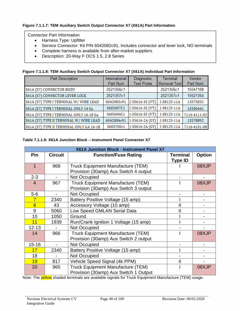
Navistar Electrical Systems CV
Integration Guide
Page 48 of 100 Revision Date: 06/01/2020
Figure 7.1.1.7: TEM Auxiliary Switch Output Connector X7 (X61A) Part Information
Figure 7.1.1.8: TEM Auxiliary Switch Output Connector X7 (X61A) Individual Part Information
Table 7.1.1.9: X61A Junction Block – Instrument Panel Connector X7
X61A Junction Block - Instrument Panel X7
Pin Circuit Function/Fuse Rating Terminal Type ID
Option
1 968 Truck Equipment Manufacture (TEM) Provision (30amp) Aux Switch 4 output
I 08XJP
2-3 - Not Occupied - -
4 967 Truck Equipment Manufacture (TEM) Provision (30amp) Aux Switch 3 output
I 08XJP
5-6 - Not Occupied - -
7 2340 Battery Positive Voltage (15 amp) I -
8 43 Accessory Voltage (10 amp) II -
9 5060 Low Speed GMLAN Serial Data II -
10 1050 Ground I -
11 1939 Run/Crank Ignition 1 Voltage (15 amp) I -
12-13 - Not Occupied - -
14 966 Truck Equipment Manufacture (TEM) Provision (30amp) Aux Switch 2 output
I 08XJP
15-16 - Not Occupied - -
17 2340 Battery Positive Voltage (15 amp) I -
18 - Not Occupied - -
19 817 Vehicle Speed Signal (4k PPM) II -
20 965 Truck Equipment Manufacture (TEM) Provision (30amp) Aux Switch 1 Output
I 08XJP
Note: The yellow shaded terminals are available signals for Truck Equipment Manufacture (TEM) usage.
Connector Part Information
• Harness Type: Upfitter
• Service Connector: Kit P/N 6042082c91, Includes connector and lever lock, NO terminals
• Complete harness is available from after-market suppliers
• Description: 20-Way F OCS 1.5, 2.8 Series

Navistar Electrical Systems CV
Integration Guide
Page 49 of 100 Revision Date: 06/01/2020
Wiring can be routed from inside cab to outside of cab by using the provided pass through
grommet. See (Figure 5.1.10) This is located on cowl driver-side.
Figure 7.1.1.10: Wire Harness Pass-thru location
Figure 7.1.1.9: Provisions at Junction Block - Instrument Panel (8XJP)
Truck Equipment Manufacture (TEM) Wire Harness Pass-thru

Navistar Electrical Systems CV
Integration Guide
Page 50 of 100 Revision Date: 06/01/2020
7.1.2. International Factory Feature 08XLS – Switch, Auxiliary, 6 Switches with 20-Amp fuses, Accessory Controlled, with Switches in Headliner (Same as GM feature RPO UEH)
Applicable with Navistar CV Trucks, built with production installed feature 08XLS. Located in the headliner just behind the overhead console sunglass storage compartment. (see Figure 7.1.2.1). The auxiliary overhead switch bank consists of (6) two position, latching, rocker style switch modules with an ON/OFF indicator window defining ignition ON or switch activated. This bank of switches provides additional controlled power circuits via blunt cut wire outputs. Can be used for controlling add-on equipment for vocational applications. Figure 7.1.2.1: Overhead Auxiliary Switches
A dedicated electrical center is added to the vehicle. Located on the rear wall of the vehicle cab. Near the electrical center are marked blunt cut wires. (see Figure 7.1.2.2) Figure 7.1.2.2: Overhead Switches dedicated electrical center

Navistar Electrical Systems CV
Integration Guide
Page 51 of 100 Revision Date: 06/01/2020
Figure 7.1.2.3: Overhead Switches Schematics (1 of 2)
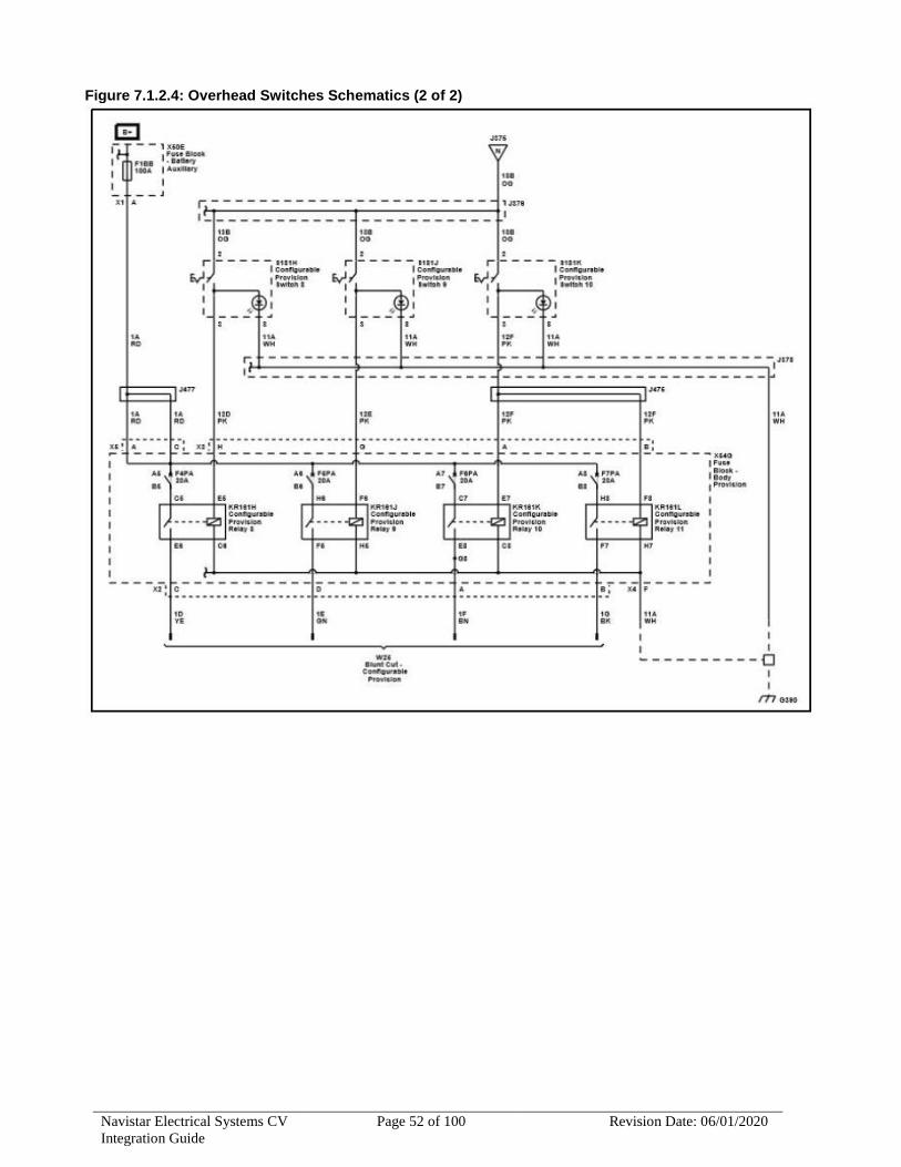
Navistar Electrical Systems CV
Integration Guide
Page 52 of 100 Revision Date: 06/01/2020
Figure 7.1.2.4: Overhead Switches Schematics (2 of 2)

Navistar Electrical Systems CV
Integration Guide
Page 53 of 100 Revision Date: 06/01/2020
7.1.3. International Factory Feature 08XJG – Fog Lights, Halogen Rectangular (Same as GM feature RPO T3U)
Factory installed optional feature provides Fog Lights at front bumper.
If equipped, the control is on the center of the exterior lamp control, located to the left of the steering column Press to turn the fog lights ON and OFF. A Light will illuminate in the gauge cluster. When the fog lights are on, the parking lights automatically turn ON. When the headlights are changed to high beam, the fog lights go OFF. Figure 7.1.3.1: Fog Light Schematic

Navistar Electrical Systems CV
Integration Guide
Page 54 of 100 Revision Date: 06/01/2020
7.1.4. International Factory Feature 08WTT – Auxiliary Switch for Worklight (Same as GM feature RPO UEH)
Factory installed feature provides worklight switch in center console for customer installed light. When ordered, the feature will utilize the cargo light switch. All the cargo functions will be active. A separate plug (E33) will be labeled cargo lamp, will be available for customer installed work light. Light must be less than 10A. Figure 7.1.4.1: Work/Cargo Light schematic

Navistar Electrical Systems CV
Integration Guide
Page 55 of 100 Revision Date: 06/01/2020
7.1.5. International Factory Feature 08XKS – Auxiliary Switch for Roof Beacon/Worklight (Same as GM feature RPO TRW)
Provides accommodations for customer supplied Beacon or Worklight. Switch located in the overhead console. A relay and blunt cut wires are also found behind the console. Blunt cut wires are only 2 inches in length. Figure 7.1.5.1: Overhead Console
Roof Console Removal To access the blunt cut wires for the roof beacon. Remove center section of the Roof Console as follows 1.. Use a flat bladed plastic trim tool in order to release the retainer clips securing the trim plate to the roof console assembly 2.. Disconnect electrical connections where/when required.
Figure 7.1.5.2 Top View of Removed Overhead Roof Console
2” Blunt Cut wires for Roof Beacon are tucked up above the Over-head Roof Console.

Navistar Electrical Systems CV
Integration Guide
Page 56 of 100 Revision Date: 06/01/2020
Figure 7.1.5.3: Schematic for Auxiliary Roof switch
Fuse for Roof Beacon Relay
Fuse for Roof Beacon Power

Navistar Electrical Systems CV
Integration Guide
Page 57 of 100 Revision Date: 06/01/2020
7.2. Body Builder Wiring and Harness
7.2.1. International Factory Feature 08TUM – Auxiliary Harness – Y-Harness for Plow Applications (Same as GM feature RPO UNL)
This feature provides a Y-harness for the installation of front mounted plow lights. Harness provides head lights, marker lights and turn signal connections. Figure 7.2.1.1: Y-Harness for Snowplow lights
Harness is typically shipped loose in the cab. Two harnesses are provided – one rights side – one left side. Both harnesses are the same part number. (4089337c94) Harness is connected directly to the head light harness. Remove the headlight connector from headlight and attach Y-Harness. Figure 7.2.1.2: Y-Harness for Snowplow lights
This feature requires other features: - 10WWS – Snowplow Prep Package - 08XKS – Worklight Switch - 08GJB or 08GJC – Alternator package
HEADLIGHT CONNECTOR

Navistar Electrical Systems CV
Integration Guide
Page 58 of 100 Revision Date: 06/01/2020
7.2.2. Body Builder Wiring – Factory Feature 08HXV – Back of Cab (Same as GM feature RPO 5DX)
Factory installed feature provides for Body Builder wiring connection at back of standard cab, left side frame rail. Connection will be found in same relative position under cab for extended or crew cabs. Feature includes one sealed connector for separate Ground / Backup/ Left-Side Turn / Right-Side Turn / Left-Side Tail / Right-side Tail / Stop / Accessory Power / Combined Left-Side Stop/Turn / Combined Right-Side Stop/Turn. Figure 7.2.2.1: Schematic for Back of Cab Body Builder Wiring – 08HXV

Navistar Electrical Systems CV
Integration Guide
Page 59 of 100 Revision Date: 06/01/2020
Figure 7.2.2.2: Body Builder Connector Information

Navistar Electrical Systems CV
Integration Guide
Page 60 of 100 Revision Date: 06/01/2020
7.2.3. Body Builder Wiring – Factory Feature 08HXU – Rear of Frame (Same as GM feature RPO 5DY)
Factory installed feature provides for Body Builder wiring connection at END of frame, right side. Feature includes one sealed connector for separate Ground / Backup/ Left-Side Turn / Right-Side Turn / Left-Side Tail / Right-side Tail / Stop / Accessory Power / Combined Left-Side Stop/Turn / Combined Right-Side Stop/Turn. Figure 7.2.3.1: Schematic for Back of Cab Body Builder Wiring – 08HXU

Navistar Electrical Systems CV
Integration Guide
Page 61 of 100 Revision Date: 06/01/2020
Figure 7.2.3.2: Body Builder Connector Information

Navistar Electrical Systems CV
Integration Guide
Page 62 of 100 Revision Date: 06/01/2020
7.3. Stop, Turn, Tail-lights and Wiring
7.3.1. Stop, Turn, Tail-lights – Factory Feature 08TUL (Same as GM feature RPO TR1)
Factory installed feature providing Multi-function sealed incandescent STOP, TURN and TAIL lights. Feature also includes backup lights with rear reflex reflector and license plate light. Figure 7.3.1.1: Schematic for Stop, Turn, Tail and Back-Up Lights

Navistar Electrical Systems CV
Integration Guide
Page 63 of 100 Revision Date: 06/01/2020
7.3.2. Stop, Turn, Tail Lights – Factory Feature 08TUK (Same as GM feature RPO UGE)
Factory installed feature providing Multi-function sealed LED STOP, TURN and TAIL lights. Feature also includes backup lights with rear reflex reflector amd license plate light. Figure 7.3.2.1: Stop, Turn, Tail and Back-Up Lights
Figure 7.3.2.2: Stop, Turn, Tail and Back-Up Lights - LED

Navistar Electrical Systems CV
Integration Guide
Page 64 of 100 Revision Date: 06/01/2020
7.3.3. Stop, Turn, Tail-lights – Factory Feature 08TKD
Factory installed feature OMITTING STOP, TURN and TAILlights. Feature does not remove wiring to end of frame. Does not include license plate light.
7.3.4. Tail Light Wiring Modified – Factory Feature 08NAA
Factory installed feature which provides extension harnesses for the standard left and right taillights. The extension harness is 8 feet long and connects to the standard rear harness. Allowing body companies to move factory lights without adding addition wiring. Extension harness part numbers 4117411c91 Harness, Left Taillight 4117413C91 Harness, Right Taillight

Navistar Electrical Systems CV
Integration Guide
Page 65 of 100 Revision Date: 06/01/2020
7.4. Trailer Connections and Controls
7.4.1. Trailer Connection Socket – Factory Feature 08TRA (Same as GM feature RPO UY7)
Factory installed feature providing trailer connection socket, mounted at rear of frame. Socket provides turn signals combined with stop. This feature is compatible with trailer having combined Stop, Tail and Turn lamps. Figure 7.4.1.1: Trailer Connection lighting Circuit Schematic Figure 7.4.1.2: Trailer Connection Power Circuit Schematic

Navistar Electrical Systems CV
Integration Guide
Page 66 of 100 Revision Date: 06/01/2020
Figure 7.4.1.3: Trailer Connection lighting Circuit Schematic

Navistar Electrical Systems CV
Integration Guide
Page 67 of 100 Revision Date: 06/01/2020
7.4.2. Trailer Brake Control, Integrated – Factory Feature 08HBW (Same as GM feature RPO JL1)
Factory installed feature providing integrated electric trailer brake control. Feature provides switch in dash and output to trailer connection. Figure 7.4.2.1: Integrated Trailer Brake Control Schematic Figure 7.4.2.2: Integrated Trailer Brake Control Schematic

Navistar Electrical Systems CV
Integration Guide
Page 68 of 100 Revision Date: 06/01/2020
7.5. Back-Up Alarm Electric 102 dBa – Factory Feature 08THB (Same as GM feature RPO UZF)
Factory installed optional feature provides an audible warning signal whenever the vehicle is operated in reverse gear. 102 dBa back-up alarm located at rear of frame. Figure 7.5.1: Back-Up Alarm Schematic

Navistar Electrical Systems CV
Integration Guide
Page 69 of 100 Revision Date: 06/01/2020
7.6. Power Inverter – Factory Feature 08XJX - (Same as GM feature RPO KI4)
Factory installed optional feature provides 12-volt DC to 110-volt AC power inverter. 110 plug is located in instrument panel or center console. Power inverter has a maximum of 150 watts. Figure 7.6.1: Power Inverter Schematic
8. Auxiliary Battery Connections
Note: Frequent field issues have been encountered with systems that move the OEM under-hood battery. Issues such as frequent Diagnostic trouble codes, improper transmission controller operation [rough shifting and clutch slip problems] as well as intermittent no crank issues have been reported. In many cases, the issue is resolved by restoring the OEM battery and cables to factory arrangement.

Navistar Electrical Systems CV
Integration Guide
Page 70 of 100 Revision Date: 06/01/2020
8.1. Repair/Recommendation: Relocation of the OEM under-hood battery should be avoided whenever possible. The following guidelines are offered for issue resolution.
1. For 2016 and newer units, the Navistar recommended auxiliary battery configuration is the factory option TP2 - Battery, 600 cold-cranking amps primary, isolated 2nd heavy-duty 770 cold-cranking amps which allows 2nd battery to be used when the vehicle is not running without affecting ability to start the vehicle.
2. If remote batteries are required [ex: tray batteries] – see ‘additional Information’ below.
8.2. Additional Information:
Batteries may be located outside the engine compartment. When this is done the following is recommended:
Negative Cable Recommendations:
[a] The first and “most recommended” method for remote battery negative cabling is a jumper cable between the battery terminals with a single ‘home run’ cable directly to the engine block. [b] An alternate - less recommended - method is using the frame as part of the negative cable path. When this is done it is essential that appropriate sized cables are used. The cable from the tray battery negative terminals to the frame and the cable from the frame to the engine block [or a transmission-to-engine mounting bolt] should be the same gauge. [c] Welded studs - added to the frame - are recommended for the two required connection points. [The frame bolt-clamping connection method presents multiple failure modes and is not recommended.] [d] The OEM negative battery cable will be too small for re-purposing to this task. Note: It is essential that the negative ground return path is not compromised. Merely grounding the tray batteries to the frame WILL NOT WORK. Extra care must be used to assure adequate current flow path to the engine/transmission castings. The high current path is from the battery negative terminal to the starter motor casting. The engine block is main ground and the frame and body are secondary. The OEM frame grounding is not sufficient if the frame is used as ‘part of the negative battery cable.’ and the additional cable to the engine/trans casting is required for this case. The body grounding cable must be maintained in all cases.
8.2.1. Positive Cable Recommendation.
[a] The first and “most recommended” method for remote battery positive cables is a jumper between the battery terminals with a single main ‘home run’ cable to

Navistar Electrical Systems CV
Integration Guide
Page 71 of 100 Revision Date: 06/01/2020
the starter motor solenoid terminal. [b] Connections to generators and main electrical center should be made at the starter motor solenoid [most recommended]. [c] If the stacking of multiple cables on the starter solenoid stud is a problem a single main cable to a junction block may be indicated. The junction block can facilitate the required connections for the generator[s] and main electrical center.

Navistar Electrical Systems CV
Integration Guide
Page 72 of 100 Revision Date: 06/01/2020
Figure 8.2.1: Remote Battery Connections Schematic

Navistar Electrical Systems CV
Integration Guide
Page 73 of 100 Revision Date: 06/01/2020
8.3. Jump Start Stud - Factory Feature 08WBW - (Same as GM feature RPO BTN) Factory installed optional feature provides a positive remote jump start stud. The stud is located near battery box, fitted with a RED cap. Figure 8.3.1: Remote Jump Start Stud Figure 8.3.2: Remote Jump Start Stud schematic

Navistar Electrical Systems CV
Integration Guide
Page 74 of 100 Revision Date: 06/01/2020
9. Rearview Camera Installation
Note: Navistar Dealers and truck equipment manufactures requiring instruction and guidelines on the installation of rearview cameras on Navistar CV vehicles. The following are guidelines intended to assist with the installation process. Furthermore, compliance to all FMVSS rules and regulations are the responsibility of the camera system integrator.
9.1. Mounting the Camera Fabrication of brackets and, or mounts for the mounting of the camera is the responsibility of the truck equipment manufacture. Mounting location should be determined by case by case to maximize the field of view and image display quality requirement set forth by the National Highway and Transportation Safety Administration (NHTSA). The NHTSA has published test procedures available which may be downloaded to aid in establishing a mounting location that meets the standards. https://www.nhtsa.gov/
2019 and later Navistar CV vehicles: It is the truck equipment manufacture’s responsibility to ensure FMVSS111 regulatory adherence.
Regular Production Option (RPO) UVC provides the following content for facilitating the installation of a rear-view camera.
• Rear camera calibration installed at assembly plant
• One camera unit complete with pigtail wiring
• Fixed zero pitch mounting bracket
• One wire harness extension
9.2. Camera Installation Guidelines
• Install camera into the provided mounting bracket using the provided two screws (not shown but included).
• Optimal position for the camera (using the included OEM bracket) is the centerline of the vehicle at a height of 38” off the ground, with zero-inch set-back from the rear most portion of the vehicle/body.
• An allowable distance of two inches off the centerline of the vehicle and no more than a range of 24” to 48” off the ground with a set-back distance of no more than eight inches from the rear of the vehicle/body represents the maximum distances with which the OEM bracket is capable of meeting the requirements defined in FMVSS111. Note: by increasing the set-back distance from the rear of the vehicle this additional distance will result in the increase in the vertical range of the camera.
• Other mounting locations and strategies requiring a different camera mounting solution shall be the responsibility of the camera system installer.
Note: These components are all shipped inside the vehicle cab

Navistar Electrical Systems CV
Integration Guide
Page 75 of 100 Revision Date: 06/01/2020
Figure 9.1.1: Camera Extension Harness, Mounting Bracket
Figure 9.1.2: Camera Harness End of Frame Mounted Connector
Note: Vehicles not ordered/manufactured with 8RNY option currently can be retrofitted, will require chassis wiring updates along with programming updates to enable Back-Up camera.
Extension harness
Mounting Bracket (Includes 2 not shown screws for securing camera to bracket)
Camera w/pigtail
Camera connection at rear of chassis

Navistar Electrical Systems CV
Integration Guide
Page 76 of 100 Revision Date: 06/01/2020
9.3. Camera System, Rear View – Factory Feature 08RNY – (Same as GM feature UVC) Factory installed optional feature provides rear view camera system. Feature includes camera, mounting brackets, wiring and interface to the monitor. Feature is available with standard radio and Human Machine Interface Control Module (HMICM) When the transmission is placed into REVERSE, a signal indicates to the radio or HMICM and image display is requested. The system receives ignition voltage and a constant ground to power the camera. Video signal + and video signal – circuits carry the video image from the camera to the monitor. The video signal circuits are shielded to prevent any interference. If a malfunction is detected in the system, “Service Rear Vision Camera” may be displayed on the info display module. Figure 9.3.1: Camera schematic with HMICM

Navistar Electrical Systems CV
Integration Guide
Page 77 of 100 Revision Date: 06/01/2020
Figure 9.3.2: Camera schematic with Radio
10. Infor – Radio Telephone/Mobile radio (Transceiver) Installation and troubleshooting Guidelines The following information is being provided to assist in the installation and troubleshooting of radio telephone/mobile radios. Certain radio telephones or land mobile radios also known as radio transceivers, the way in which they are installed, may adversely affect various vehicle operations such as engine performance, driver information, entertainment and electrical systems. Expenses incurred to protect the vehicle systems from any adverse effects of any such installation are not the responsibility of Navistar Corporation.

Navistar Electrical Systems CV
Integration Guide
Page 78 of 100 Revision Date: 06/01/2020
The following are general guidelines for installing a radio transceiver in Navistar vehicles. These guidelines are intended to supplement, but not to be used in place of, detailed instructions which are the sole responsibility of the manufacturer of the involved radio transceiver. Although this document refers to passenger vehicles, the same general guidelines apply to trucks.
10.1. Transceiver Location • Locate transceiver for remote radios on driver’s side, as near to the vehicle
body side as possible. • One-piece transceivers should be mounted under the dash or on transmission
hump where they will not interfere with vehicle controls or passenger movement.
• Great care should be taken not to mount any transceivers, microphones, speakers or any other item in the deployment path of a Supplemental Inflatable Restraint (air bag).
10.2. Antenna Installation • Each vehicle model and body style react to radio frequency energy differently.
When dealing with an unfamiliar vehicle, it is suggested that a magnetic-mount antenna be used to check the proposed antenna location for unwanted effects on the vehicle. Antenna location is a major factor in these effects.
• The antenna should be a permanent-mount type located in the center of the roof or center of the rear deck lid. Glass mounted antennas should be kept as high as possible in the center of the rear window or windshield. If a magnet-mount antenna is used, care should be taken to mount the antenna in the same location as a permanent-mount type. If a disguise-mount antenna is used, great care should be taken to shield any tuning network from vehicle electronics and wiring, or to mount the tuning network in an area completely clear of vehicle electronics and wiring.
• Standard metal mount antennas may be mounted on a vehicle with nonmetallic body panels by two methods. Most nonmetallic skinned vehicles have metal frames underneath. Mounting the antenna near a metal frame section and bonding the antenna mount to the frame with a short metal strap will provide the ground plane connection. Some antenna manufacturers offer “ground plane kits” that consist of self-adhesive metal foil that may be attached to the body panel to provide the ground plane for the antenna.
• Some vehicles use glass that contains a thin metallic layer for defrosting or to control solar gain. Glass mount antennas will NOT function when mounted on this type of glass.
• If RF-related interactions occur when using a hitch or bumper-mount HF antenna on a vehicle that has body on frame construction (i.e. pickup, SUV) connect a ground strap from the vehicle frame to the bottom rear of the vehicle body (for station wagon type vehicles), or from the vehicle frame to the bottom rear of the cab (pickup style vehicles).

Navistar Electrical Systems CV
Integration Guide
Page 79 of 100 Revision Date: 06/01/2020
10.3. Antenna Cable Routing • Always use a high-quality coax (at least 95% shield coverage) located away
from the engine control module (ECM) and other electronic modules. • Care should be taken to maintain as great a distance as possible between any
vehicle wiring and the feed line. 10.4. Antenna Tuning
It is important that the antenna be tuned properly and reflected power be kept to less than 10% (VSWR less than 2:1).
10.5. Radio Wiring and Connection Locations • Connecting radio power on Navistar vehicles is model dependent. The installer
must decide which one of the following four methods will be appropriate. ▪ Connect the positive and negative leads directly to the battery terminals
(illustrated in this guideline). ▪ Connect the positive lead to the auxiliary power terminal (located at the
under-hood fuse center or identified by a red plastic cover in the under-hood area) and connect the negative lead directly to the negative battery terminal.
▪ Connect the positive lead to the auxiliary power terminal and connect the negative lead to the battery body connection point (identified by a short #10 AWG or larger wire running from the negative battery terminal to the body of the vehicle).
▪ Connect the positive and negative leads to the Special Equipment Option (SEO) wiring provided for this purpose.
• If connections are made directly to the battery terminals, the Navistar-approved methods of connecting auxiliary wiring include the adapter package illustrated in Figure 2, NAPA-Belden replacement battery bolts, P/N 728198, or drilling and tapping the hex end of the original battery bolts 10-32 X 3/8” deep. Note that it is recommended that a fuse be placed in the transceiver negative lead to prevent possible transceiver damage in the event the battery-to-engine block ground lead is inadvertently disconnected.
• For ONE-PIECE TRANSCEIVERS where ignition switch control is desired, and no SEO wiring exists, a 12volt power contactor must be installed in the transceiver positive lead. The contactor should be located near a proper 12volt feed. The coil of the contactor should be connected through an appropriate in-line fuse to an available accessory circuit or ignition circuit not powered during cranking. The contactor coil must return to a proper negative point.
• Any negative lead from a handset or control unit must return to a proper negative connection point. It is preferable that the positive lead for a handset or control unit be connected directly to a proper positive feed. If ignition switch control is desired, the handset or control unit positive lead may be connected through an appropriate in-line fuse to an available accessory circuit or ignition circuit not powered during cranking. It is recommended that the handset or control unit positive and negative leads be appropriately fused separately from the transceiver positive and negative leads.
• If multiple transceivers or receivers are to be installed in the vehicle, power leads to the trunk or under dash should be connected to covered, insulated terminal strips. All transceivers or receivers may then have their power leads connected to the strips. This makes a neater installation and reduces the number of wires running to the vehicle under hood area.

Navistar Electrical Systems CV
Integration Guide
Page 80 of 100 Revision Date: 06/01/2020
10.6. Radio Wire Routing
• The power leads should be brought through a grommet hole in the front bulkhead that must be provided by the installer. All attempts should be made to maintain as great a distance as possible between radio power leads and vehicle electronic modules and wiring.
• If the battery is located on the passenger side, radio power leads should cross the vehicle in front of the engine.
10.7. Troubleshooting • Should vehicle-radio interaction develop following installation, the source of the
problem should be determined prior to further operation of the vehicle. Most interaction problems can be eliminated by following the installation guidelines.
• If any vehicle-radio interaction problems exist after following these guidelines, refer to the EMC Troubleshooting Chart at the end of this bulletin.
Figure 9.1.3: Auxiliary Electrical Equipment – Navistar Recommended Installation
Table 9.1.3: Part Numbers and Descriptions
Part Number and Descriptions
1) Vehicle Battery Cable (2) Vehicle Battery
(3) Contact Spacer (4) Adapter Terminal (part of kit 1846855)
(5) Long Battery Terminal Bolt (6) Terminal Cover (part of kit 1846855)
(7) Wire Connector (part of kit 1846855)
(8) Insulation Boot (part of kit 1846855)
(9) Auxiliary Equipment Cable(s)

Navistar Electrical Systems CV
Integration Guide
Page 81 of 100 Revision Date: 06/01/2020
Table 9.1.4: EMC Troubleshooting
EMC Troubleshooting Chart Step Action Yes No
1 Can you reproduce the concern? Go to
Step 2
Must be
able to
reproduce
the
concern.
2 Is the vehicle equipped with aftermarket
accessories such as radar detectors, remote
starters, radio transceivers, etc.
Go to
Step 3
Go to Step
6
3 Remove or disable the accessories.
Is the concern related to the operation of such
accessories?
Go to
Step 4
Go to Step
6
4 Check for ground points and correct cable routing
and antenna location.
Does the installation conform to Navistar
guidelines?
Go to
Step 6
Go to Step
5
5 Correct the installation.
Is the concern eliminated?
Concern
resolved
Go to Step
6
6 Gather the following information:
• The radio frequencies involved
• Engine ON or OFF
• Is the concern intermittent
Does a Service Bulletin or P.I. exist dealing with
this concern?
Go to
Step 7
Go to Step
8
7 Perform the procedure from the service bulletin or
P.I.
Is the concern eliminated?
Concern
resolved
Go to Step
8
8 Identify additional EMC parameters.
Is the accessory defective?
Go to
Step 9
Go to Step
10
9 Repair/replace the component.
Is the concern eliminated?
Concern
resolved
Go to Step
10

Navistar Electrical Systems CV
Integration Guide
Page 82 of 100 Revision Date: 06/01/2020
10 Inspect the circuit integrity for the following:
• Ground connections
• Connector integrity
• Cable routing
Is the circuitry acceptable?
Go to
Step 12
Go to Step
11
11 Repair the circuitry as needed.
Is the concern eliminated?
Concern
resolved
Go to Step
12
12 Consult with Technical Assistance for any
additional available information.
Parts Information
AC-Delco Side Terminal Adapter Package 1846855, when combined with the longer battery bolt and spacer will provide the simple, light, corrosion-resistant connection illustrated.
Table 9.1.5: Terminal Adapter Parts
Side Terminal Adapter Package
Description AC-Delco Catalog 7A10 Car Dealer Parts Book
Kit 1846855 1846855
Bolt 7803 12004188
Spacer 7804 12004189

Navistar Electrical Systems CV
Integration Guide
Page 83 of 100 Revision Date: 06/01/2020
11. Gauge and Fault Code Display
The International CV is available with two choices for gauge cluster. Each providing a driver information center. The driver information center will provide at a minimum the following:
• Speed
• Trip Mileage
• Fuel Range
• Average Fuel Economy
• Remaining Oil Life
• Remaining Fuel Filter Life
• DEF Level
• Transmission Fluid Temperature
• Engine Hours
11.1. Base Gauge Cluster:
The base gauge cluster has monochrome driver information center. The center will display the information above by scrolling the button stem to the right of the display. Figure 11.1.1: Base Gauge Cluster

Navistar Electrical Systems CV
Integration Guide
Page 84 of 100 Revision Date: 06/01/2020
11.2. Premium Gauge Cluster:
The premium gauge cluster has color driver information center. The center will display the information and more. Use the right-side steering wheel control buttons to scroll through the different items and displays. Figure 11.2.1: Base Gauge Cluster
12. Relocation of electrical Components/Devices-Best Practices/Recommendations
Note: During the upfit process it may, for various reasons, become necessary to remove or relocate certain electrical connections, components and/or control modules. The following are the best practices/guidelines as they pertain to these types of components
Safety Systems: Be advised that the components for the following systems…Air Bag, Anti-lock Braking, Collision Avoidance, Obstacle Detection Lane Departure and Blind Spot Warning cannot be relocated as the systems are calibrated to their location within and to the vehicle
Electrical Components (non-safety system related) When relocating electrical components careful consideration needs to be given as to environmental conditions of the new location. Such things such as moisture, temperature, electromagnetic interference, signal interference/impediment.
12.1. Under-hood/Vehicle: When relocating components outside the passenger compartment of the vehicle steps to protect the device/component from high heat sources such exhaust system, engine block, cooling system and their associated parts/sub-assemblies. Consideration to the possibility of water/moisture intrusion must also be given, many outside areas of the vehicle are often subject to water splash and/or spray so the components must be protected by a water tight housing with proper weather protected connector and seal

Navistar Electrical Systems CV
Integration Guide
Page 85 of 100 Revision Date: 06/01/2020
assemblies. Consideration to all moving parts/components is required when selecting a new location
12.2. Under-dash: Components being considered for relocation inside of the passenger compartment need to have the same environmental considerations given as to the selected location. Components to be mounted under dash/above the driver/operator foot controls must secured so not impose a risk of dislodging and impeding the operation of any of the vehicles foot controls. Under dash mounting must also not impede the operation of any of the vehicles sub-systems. 12.3. Doors: When relocating components within the doors consideration shall be taken to moving parts and environment. When considering a new location for component/s be aware of the travel path of the moving window and its components. Also, being sure not to impact any of the door latching/release systems. Additionally, reinstallation of the door’s water deflection system/shields is required to prevent water intrusion inside the vehicle. Electrical system components should never be relocated to the “wet” side of the water deflection system. To prevent water intrusion into components inside of the door, connector interfaces should always be positioned in a downward orientation. It is also suggested that wire harnesses be routed with a drip loop near or at the device whenever possible.
12.4. Under Seats: When relocating components under or near the seats consideration shall be taken regarding all moving parts and their subsequent environments. When considering a new location for component/s be aware of the travel path of the moving seat and its components. Also, being sure not to impact any of the seat’s latching/release systems. Many front driver and passenger seats have integrated safety components that too must not be interfered with as well. Consideration to the seat belt system and its moving and latching system must also be given.
12.5. Rear Stowage Areas: When relocating components under or near the seats consideration shall be taken regarding all moving parts and their subsequent environments. Additionally, once again environment must consider when mounting or locating a device in this area to the “drip zone” of water/moisture dripping off the rear stowage area enclosure. Be sure that when the enclosure is opened that any water or moisture that may be on the enclosure won’t drip onto the mount device/components.
12.6. General Recommendation: Lastly, consideration shall be given to all possible impacts to the vehicle’s operator and occupants when adding or relocating electrical devices
13. Appendix - General Electrical Section: Description - International vehicle electrical systems are becoming increasingly complex with the addition of a Body Controller, electronic engine and transmission controls, electronically driven instrument gauges, and Antilock Brake Systems (ABS) to name a few. While most systems still operate on battery voltage (12volts), some systems operate at as high as 107 volts (electronic fuel injection) and as low as five (5) volts (electronic engine controls).

Navistar Electrical Systems CV
Integration Guide
Page 86 of 100 Revision Date: 06/01/2020
International publishes Electrical Circuit Diagram Manuals for all its models. Body builders
and installers should refer to these manuals before connecting body lights and accessories to
the vehicle electrical system to assure that circuits chosen are both appropriate and not
overloaded. Modifications not defined in the circuit diagram book are not to be made to the
vehicle electrical/electronic control systems without first contacting International for
assistance at its Tech Central Department, telephone 1-800-336-4500.
13.1. Color Code System for International® Truck Wiring: Wiring Color Code System:
COLOR DESCRITION
RED ALTERNATOR/BATTERY FEEDS
PINK IGNITION FEEDS
LIGHT BLUE ACCESSORY FEEDS
YELLOW HEADLIGHT SYSTEM (DAYTIME RUNNING LIGHTS, FOG, HI-BEAM, ETC.);
DATA LINK J1939 (+)
DARK BLUE INTERIOR LIGHTS (DOME, PANEL, ETC.); DATA LINK J1708 (+)
BROWN EXTERIOR LIGHTS (TAIL, MARKER, CLEARANCE, ETC.)
ORANGE EXTERIOR LIGHTS (TURN, BACK-UP, ETC.)
GRAY ENGINE / CHASSIS SYSTEMS (FUEL SOLENOID, HORN, ETC.); DATA LINK
J1708 (-)
TAN ENGINE / CHASSIS MONITORING SYSTEMS (GAUGES)
GREEN DATA LINK J1939 (-)
LIGHT GREEN DRIVER AID SYSTEMS (WINDSHIELD WASHER, HEATER, ETC.)
VIOLET ENGINE CONTROLS - ELECTRONIC
WHITE GND
BLACK BATTERY GND CABLES OR COMPUTER DATA LINK SYSTEMS
NOTE: THE WIRING IN MULTIPLE CONDUCTOR JACKETED CABLE DOES NOT FOLLOW THE
ABOVE COLOR CODE SYSTEM. SEE THE ELECTRICAL CIRCUIT DIAGRAM MANUAL FOR
SPECIFIC COLORS AND CIRCUIT NUMBERS USED WITH EACH SYSTEM. USE ONLY “GXL", “SXL"
OR “TXL" INSULATED WIRE. CRIMP AND SOLDER ALL CONNECTIONS.
Wiring Color Code Table
13.2. Recommended Circuit Protection: Circuit Protection by Wire Gauge:
WIRE GAUGE PROTECTIVE DEVICE SIZE MAXIMUM CURRENT (AMPS)
18-GUAGE 10 AMP FUSE/ CIRCUIT BREAKER 8 A
16-GUAGE 15 AMP FUSE/ CIRCUIT BREAKER 12 A
14-GUAGE 20 AMP FUSE/ CIRCUIT BREAKER 16 A
12-GUAGE 25 AMP FUSE/ CIRCUIT BREAKER 20 A
10-GUAGE 30 AMP FUSE/ CIRCUIT BREAKER 24 A
8-GUAGE 12 GAUGE FUSIBLE LINK 80 A
6-GUAGE 10 GAUGE FUSIBLE LINK 108 A
4-GUAGE 2–12 GAUGE FUSIBLE LINK 160 A

Navistar Electrical Systems CV
Integration Guide
Page 87 of 100 Revision Date: 06/01/2020
CAUTION - WIRE GAUGE IS DESIGNED TO MATCH FUSE / CIRCUIT BREAKER RATING. DO NOT
INCREASE THE SIZE OF A CIRCUIT BREAKER OR FUSE. TO DO SO COULD CAUSE WIRING TO
OVERHEAT AND BURN.
Circuit Protection by wire Gauge Table
Circuit Protection Devices - Fuses and Circuit Breakers:
PART NUMBER DESCRIPTION SIZE COLOR
CIRCUIT BREAKERS
3536177C1 TYPE III — MANUAL RESET 7.5 A BROWN
3536178C1 TYPE III — MANUAL RESET 10 A RED
3536179C1 TYPE III — MANUAL RESET 15 A BLUE
3536180C1 TYPE III — MANUAL RESET 20 A YELLOW
3536181C1 TYPE III — MANUAL RESET 25 A WHITE
3536182C1 TYPE III — MANUAL RESET 30 A GREEN
3529688C1 TYPE III - MINI 20 A YELLOW
3529690C1 TYPE III - MINI 30 A GREEN
THERMAL FUSES
3534208C1 MINI — SAE J2077 5 A TAN
3546109C1 MINI — SAE J2077 7.5 A BROWN
3534209C1 MINI — SAE J2077 10 A RED
3534210C1 MINI — SAE J2077 15 A BLUE
3534211C1 MINI — SAE J2077 20 A YELLOW
3534212C1 MINI — SAE J2077 25 A NATURAL
3534213C1 MINI — SAE J2077 30 A GREEN
131224C1 AUTOFUSE 20 A YELLOW
571691C1 AUTOFUSE 30 A GREEN
INLINE SOCKET AND CABLE FOR CIRCUIT BREAKER/FUSE
1676841C91 INLINE SOCKET WITH CABLE 20 A BLACK
1682115C91 INLINE SOCKET WITH CABLE 30 A BLACK
Fuse and Circuit Breaker Protection Device Table
13.3. Electrical Components Commonly Used by Equipment Installers: Components Table:
PART NUMBER DESCRIPTION
AT FUSE BLOCK
3536294C1 TERMINAL, FUSE BLOCK (18/20 GAUGE)
3573312C1 TERMINAL, FUSE BLOCK (14/16 GAUGE)
3573311C1 TERMINAL, FUSE BLOCK (10/12 GAUGE)
AT TAIL LIGHTS
589390C1 SEAL, WIRE - (BLUE) .165-.138 O.D. CABLE (12-14 GAUGE)
589391C1 SEAL, WIRE - (GRAY) .137-.111 O.D. CABLE (14-16 GAUGE)
1652325C1 SEAL, WIRE - (LT GN) .110-.080 O.D. CABLE (16-20 GAUGE)
1661375C2 BODY CONNECTOR, 5-WAY MALE
1661377C1 TERMINAL, FEMALE - 14/16 GAUGE
1661376C1 LOCK, 5-WAY MALE CONNECTOR
1677851C1 BODY CONNECTOR, 5-WAY FEMALE

Navistar Electrical Systems CV
Integration Guide
Page 88 of 100 Revision Date: 06/01/2020
1671609C1 TERMINAL, MALE - 14/16 GAUGE
1677914C1 LOCK, 5-WAY FEMALE CONNECTOR
587579C1 SEALING PLUG (FOR EMPTY CONNECTOR CAVITIES)
NOTE - ANY UNUSED CIRCUIT CAVITIES MUST BE PLUGGED WITH SEALING PLUGS PROVIDED
WITH CHASSIS HARNESS.
Commonly Used Electrical Integration Small Components Table
13.4. Wire Splicing and Termination - Standard Terminals and Splices:
Standard Terminals 1. Cut the cable just before the insulation wings on the terminal.
2. Remove the insulation being careful not to cut any of the wire strands.
3. Position cable in the new terminal.
4. Hand crimp the core wings first, then the insulation wings.
NOTE - Always use the recommended crimp tool for each terminal. A detailed crimp chart is
included in the repair kit.
5. Solder all hand crimped terminals and electrically check for continuity.
Standard Terminal
1. MATING END 2. CORE WINGS 3. INSULATION WINGS 4. CABLE 5. LOCK TANG 6. INSULATION 7. WIRE STRANDS 8. SOLDER Splice Inspection:

Navistar Electrical Systems CV
Integration Guide
Page 89 of 100 Revision Date: 06/01/2020
Splice Inspection
A. TERMINAL APPLICATION 1. INSULATION CRIMP 2. WIRE STRANDS VISIBLE IN THIS AREA 3. CORE CRIMP B. SOLDER APPLICATION 4. GOOD SOLDER APPLICATION C. CRIMP AND SEAL HEAT APPLICATION 5. EVIDENCE OF GLUE Splice Clip Installation NOTE - A new clip must be located a minimum of 1.5 inches (40 mm) from a connector,
sleeve or another clip.
1. Cut off the old clip or bad section of wire.
2. Remove the insulation being careful not to cut any of the wire strands.
3. Install the proper clip on the wire strands.
4. Hand crimp the clip until securely fastened.
5. Solder the clip and electrically check for continuity.
6. Cover the entire splice with splice tape. Extend the tape onto the insulation on both sides
of the splice(s).

Navistar Electrical Systems CV
Integration Guide
Page 90 of 100 Revision Date: 06/01/2020
Splice Clip Installation
1. INSULATION 2. WIRE STRANDS 3. CLIP (POSITIONED CORRECTLY) 4. CRIMPED CORRECTLY 5. SOLDER 6. TAPE Crimp and Seal Splice Sleeve Installation: Parts Information:
Part Number Description Quantity 3517501C1 12-10 AWG Splice 2
3517502C1 16-14 AWG Splice 7
3517503C1 22-18 AWG Splice 2
2644000R1 Dual Wall Heat Shrink, 50mm 50
NOTE - A new sleeve must be located a minimum of 1.5 inches (40 mm) from a connector,
clip or another sleeve.
1. Cut off the old sleeve or bad section of the wire.
2. Remove insulation being careful not to cut any of the wire strands.
3. Install the proper sleeve on the wire strands, making sure the ends of the wire hit the stop.
4. Hand crimp to the sleeve. Gently tug on the wire to make sure that they are secure.
NOTE - Always use the recommended crimp tool for each sleeve. A detailed crimp chart is
included in the Repair Kit.

Navistar Electrical Systems CV
Integration Guide
Page 91 of 100 Revision Date: 06/01/2020
CAUTION - Use appropriate heat gun. Do not use a match or open flame to heat the
sleeve seal.
5. Electrically check the sleeve and wire cable for continuity.
Crimp and Seal Splice Sleeve Installation
1. WIRE STRANDS 2. WIRE STOP 3. CRIMP CONNECTOR 4. EVIDENCE OF GLUE Data Link Repair: GMLAN & J1962 Shielded Only Repairs to damaged DataLink circuits should be accomplished using identical types of wiring.
Splices should be crimped, soldered and covered with heat shrink. Ensure the twist in the
wire pair is maintained and that any wire bundles in the engine compartment are shielded
and covered with heat shrink.

Navistar Electrical Systems CV
Integration Guide
Page 92 of 100 Revision Date: 06/01/2020
Wire Repair This instruction addresses termination and splicing of J1939 wire.
Preparation of DataLink Wire for Connection
1. Strip back (view C) outer shield 3 1/8 in. (76 mm).
2. Strip (view A) green wire and yellow wire 1/4 in. (6.35 mm) being careful not to cut
individual strands.
3. Re-twist all three wires if they have separated.
4. Sleeve drain wire (view B) may be soldered to aid in sleeving.
5. Install terminals on green and yellow wire ends, and crimp.
6. The 1/4" heat shrink tube (view D) will be shrunk later after the wires have been inserted
into the crimp connector.
Wire Splicing 1. Strip wire ends 1/4 inch.
2. Re-twist any loose wires.
Re-Twist Any Loose Wires
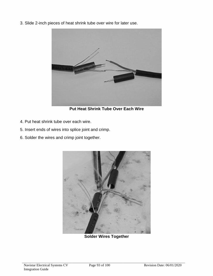
Navistar Electrical Systems CV
Integration Guide
Page 93 of 100 Revision Date: 06/01/2020
3. Slide 2-inch pieces of heat shrink tube over wire for later use.
Put Heat Shrink Tube Over Each Wire
4. Put heat shrink tube over each wire.
5. Insert ends of wires into splice joint and crimp.
6. Solder the wires and crimp joint together.
Solder Wires Together

Navistar Electrical Systems CV
Integration Guide
Page 94 of 100 Revision Date: 06/01/2020
7. Center heat shrink tube over splice and shrink.
Center Heat Shrink Tube Over Splice
8. Wrap wires with foil tape. Maintain at least 1/2 wrap overlap.
Center Heat Shrink Tube Over Cable
9. Center heat shrink tube over the splice and shrink.
Center Heat Shrink Tube Over Cable

Navistar Electrical Systems CV
Integration Guide
Page 95 of 100 Revision Date: 06/01/2020
13.5. HIGH VOLTAGE CIRCUITS (GREATER THAN 50 VOLTS) ON INTERNATIONAL
TRUCKS AND BUSES:
WARNING - To avoid property damage, personal injury, or death, refer to the manufacturer's service information before working on any high voltage equipment. By definition, high voltage circuits and components contain voltage levels that may cause
equipment damage, electrical shock, and/or electrocution if handled incorrectly.
Only a trained technician may perform service inside high voltage components. When working around or maintaining high voltage circuits, please seek high voltage training.
NOTE - The intent of this section is to provide some basic guidelines when working on or
around International vehicles that are equipped with high voltage electrical equipment and
circuits. For specific instructions, maintenance, or service information on specific equipment
or options, refer to the service manuals for the specified truck models and component(s). It IS
NOT the intent of this section to provide detailed service instructions for high voltage
equipment and circuits.
High voltage systems require the maintainer to be familiar with two types of electrical
systems.
DC (Direct Current)
Most DC systems on today's trucks use 12volt negative GND. Some systems can store DC
electricity in batteries with operating voltages as high as 600 DC volts.
AC (Alternating Current)
The main difference between AC and DC systems is that the voltage levels in DC systems
remain constant while the voltage levels in AC systems are constantly changing. When
measuring an AC system, it is important to know that the average voltage is zero, and that is
why A VOLTMETER SET TO DC WILL NOT INDICATE THE PRESENCE OF AN AC
VOLTAGE WHEN CONNECTED TO AN AC CIRCUIT!
High voltage can be lethal. Always refer to the manufacturer of the high voltage component
when maintenance or repairs are needed. In most cases, diagnostics and repair are
performed after the high voltage circuits are disabled. If working around or maintaining high
voltage circuits, please seek high voltage training.
WARNING - To avoid property damage, personal injury, or death, circuits must be checked using a voltmeter for the presence of both DC and AC voltages. A voltmeter set to DC will not indicate the presence of an AC voltage when connected to an AC circuit! Contacting an unknown AC or DC voltage may cause equipment damage,
electrical shock, and/or electrocution.
Only a trained technician may perform service inside high voltage components. If
working around or maintaining high voltage circuits, please seek high voltage training.
Understanding High Voltage Equipment and Circuits on International Products:

Navistar Electrical Systems CV
Integration Guide
Page 96 of 100 Revision Date: 06/01/2020
Some examples of high voltage equipment that can be encountered on products are as
follows:
— Auxiliary Power Units (APUs)
APUs are basically small diesel-powered generator units that are integrated into the vehicle
electrical system. APUs are utilized in combination with inverters and battery chargers. APUs
are often set up to automatically start when the electrical management system deems it
necessary to maintain battery charge or electrical demand requires it.
NOTE - APU high voltage wiring may NOT be marked for easy identification as high voltage.
— Shore Power
Shore power is a connection from a vehicle to an external 120Volt AC power source. The
vehicle is equipped with an exterior receptacle that allows connection to an external “shore”
power source.
NOTE - High voltage shore power wiring may NOT be marked for easy identification as high
voltage.
— Inverters
Inverters are electronic devices used to change DC (Direct Current) into AC (Alternating
Current). Some inverters contain converters that also convert AC to DC for battery charging
or running 12V equipment.
NOTE - High voltage wiring for inverters may NOT be marked for easy identification as high
How to Identify High Voltage Circuits: High voltage circuits are not always connected with large wires. The best way to identify high
voltage equipment or circuits is to be familiar with the equipment and circuit diagrams as well
as to look for high voltage warning labels and orange conduit. Inspect the vehicle for any
equipment or circuits added after the truck was built (owner/operators may add high
voltage components such as inverters or APUs).
All electrical circuits associated with APUs, shore power, inverters, and HEVs should be
considered high voltage. The standard for high voltage cabling on HEVs is orange. APUs,
inverters, shore power, and cabin 110/120V outlet wiring may not indicate high voltage by
visual inspection (they may not be marked and are NOT orange in color).
Servicing International Products: The following steps outline the appropriate method to follow to identify and address any
maintenance or service on International products with factory-installed high voltage
equipment.
1. Complete related training prior to attempting to identify and service any high voltage
system.
2. Review the line-set ticket provided with the vehicle or from ISIS and identify all high voltage
components. Inspect the vehicle for any equipment or circuits added after the truck was built
(owner/operators may add high voltage components such as inverters or APUs that could be

Navistar Electrical Systems CV
Integration Guide
Page 97 of 100 Revision Date: 06/01/2020
live and powering circuits in the vehicle EVEN WITH THE IGN OFF AND THE BATTERIES
DISCONNECTED).
3. Refer to manufacturer’s service publications for identified high voltage components.
4. Physically locate high voltage components on the vehicle and disable them according to
manufacturer’s instructions (some components may require a waiting period or special
procedures to discharge the voltage completely).
5. Use Best Work Practices (see below) when performing work on electrical systems.
Best Work Practices: WARNING - To avoid personal injury or death, permit only trained responsible and
capable persons to operate or maintain the equipment. Carelessly operating or neglecting maintenance despite the safe design of any vehicle and its high voltage
equipment may result in personal injury or death.
The danger of injury through electrical shock is possible whenever electrical power is
present. Most fatal injuries result from high-voltage exposure; however, people can
sustain severe injuries from low voltage power if it has a high current flow.
· Be aware of ALL high voltage equipment on the vehicle; review line-set/build ticket and the owner and service manuals of high voltage equipment BEFORE starting any work.
· When working on this equipment, remain alert at all times. Never work on the equipment when physically or mentally fatigued, and never work alone near high voltage equipment.
· Always stand on an insulated, dry surface when working on any electrical circuit. Do not handle any kind of electrical device while standing in water, while barefoot, or while hands or feet are wet.
· Always work in an adequately illuminated area. · Always use appropriate protective equipment: insulated gloves, rubber gloves,
goggles/face shield, safety shoes, protective clothing, and insulated tools when working on electrical components/circuits of the vehicle.
· Never wear jewelry when working on this equipment. Jewelry can conduct electricity resulting in electric shock or burns and may get caught in moving components causing injury.
· When working on vehicles that have high voltage devices or equipment, use appropriate alerting techniques in plain view to warn people that may be in the general area and to prevent inadvertent activation of any disabled high voltage circuit(s) during service: safety signs, safety symbols, tags, barricades, cones, etc.
· Keep a fire extinguisher close by at all times. Extinguishers rated “ABC” by the National Fire Protection Association are appropriate for use on the electrical system. Make sure the extinguisher is properly charged and be familiar with its use. Consult the local fire department with any question pertaining to fire extinguishers.
· Ensure that the high voltage power, high voltage power generating equipment, and high voltage storage devices are disconnected, locked out, or otherwise disabled BEFORE working on or around the vehicle, its electrical circuits, or components. Unless disabled, Auxiliary Power Units (APUs) may start at any time without warning; when this occurs, the circuits associated with the APU become energized with potentially lethal high voltage. Some components may require a waiting period or special procedures to discharge the voltage completely.

Navistar Electrical Systems CV
Integration Guide
Page 98 of 100 Revision Date: 06/01/2020
· Use an appropriate electrical tester and procedures to confirm that the power is disconnected BEFORE performing any work on or near any high voltage components/circuits.
· Exercise caution around output circuits even when the input power is off. Parallel power sources and energy storage devices can still be dangerous. Be familiar with the high voltage equipment installed on the vehicle. Some systems contain high voltage condensers that may require time to discharge after power is removed.
· After disconnecting or exposing a high-voltage connector or terminal, insulate it immediately using insulation tape.
· After completion of any electrical work, BEFORE restoring the power, verify that parts and/ or tools are removed from the work area and that the fasteners are firmly tightened to the specified torque and the connectors are correctly connected.
· Voltage can be fatal at levels greater than 60 volts. High voltage can jump a larger air gap than low voltage. If contact is made with high voltage, it may not be possible to simply “let go”.
· Towing a HEV with its drive wheels on the ground may cause the motor to generate electricity. Consult the operator’s/owner’s manual for proper towing procedures.
· If a high voltage fuse or circuit protection device trips, do not re-energize the circuit until it has been determined that the circuit is safe. See manufacturer’s troubleshooting procedures before servicing a high voltage system.
· Reference OSHA Regulations as necessary and applicable. Suppression: International® strongly recommends these electromagnetic devices be electrically
suppressed, when adding electromagnetic devices such as relays, magnetic switches, and
solenoids.
Unsuppressed electromagnetic devices can generate large voltage spikes which are
conducted into the vehicle electrical system. These voltage spikes may adversely affect
customer added electronic devices and in some instances may affect International installed
electronic components.
When installing electromagnetic devices, specify suppressed units. If suppressed units are
not available, diode suppression may be added as shown below:
The following suppressed relays and magnetic switches are available from International.
Suppressed Relays and Magnetic Switches:
PART NUMBER DESCRIPTION
1691520C91 MAGNETIC SWITCH - CONTINUOUS DUTY (SUPPRESSED) 100 AMP
1693479C91 MAGNETIC SWITCH - INTERMITTENT DUTY (SUPPRESSED) 100 AMP
3519350C1 MICRO RELAY – SPDT (SUPPRESSED), NO – 20 AMP, NC – 10 AMP
Welding Information: Whenever electric welding is done on any part of the vehicle, it is not necessary to disconnect
the International electronic modules in the cab such as the BC, RPM, and the instrument
cluster. The welder's GND must be connected as close to the weld as possible. If the vehicle
is equipped with an International engine, disconnect both the positive (+) and the negative (-)
battery cables including the electronic power feeds prior to electric welding. If it is necessary

Navistar Electrical Systems CV
Integration Guide
Page 99 of 100 Revision Date: 06/01/2020
to weld close to an electronic component, it is recommended that the component be
temporarily removed.
Consult manufacturer’s instructions for all other electronic modules such as Allison
Transmission, Eaton Auto Shift Transmission, Bendix ABS, Wabco ABS, Cummins Engine,
Caterpillar Engine, and Detroit Diesel Engine.
Routing Guidelines: Any hosing, tubing, battery cable, wiring or electrical harness must not rub on a sharp edge.
However, due to the high abrasion resistance of synflex tubing, it is permissible for synflex
tubing to make contact with the lower edge of the frame rail flange when the tubing is making
the transition from the outside to down and under the rail. This does not mean that proper
clearance or the need for protective wrap is not needed when synflex line contacts sharp
edges or threaded fasteners.
Any hosing, tubing, battery cable, wiring or electrical harness must not rub or make contact
with a hot surface. There should be 5" minimum clearance from the exhaust depending on
the situation. The further back from the turbo, the less clearance required.
Nothing should rub or make contact with the copper compressor discharge tubing other than
the clamp(s) that support it.
All hosing, tubing, battery cables or electrical harnesses should be supported at least every
18" to 20".
Straplocks used to directly clamp or support battery cables or main engine wiring harnesses
must be no less than 7/16" in width.
Straplocks are not to be used on any bulk hose materials (heater hoses, make-up lines, etc.).
Route and Clip Recommendations:
Heat Source:
HEAT SOURCE DISTANCE FROM
EXHAUST MANIFOLD TO MUFFLER INLET 6”
AFTER TREATMENT 8”
MUFFLER INLET TO TAIL PIPE OUT 3”
OTHER (EGR DISCHARGE PIPE/HOSE) 1/2”
Electrical Harness:
PROBLEM REQUIREMENT
SHARP OR ABRADING SURFACE NO CONTACT
TENSION ALONG HARNESS/WIRES/HOSE NONE
DISTANCE FROM MOVING PARTS 1”
CONNECTOR CLIPPED TO AVOID DAMAGE YES
CONNECTORS ARE SEALED YES
MAX EYELETS PER STUD 3
HARNESS PROTECTED FROM DAMAGE YES
DRIP POINT FOR HARNESS YES
DISTANCE OF HARNESS TO FLAMMABLE FLUIDS 1/2”

Navistar Electrical Systems CV
Integration Guide
Page 100 of 100 Revision Date: 06/01/2020
HARNESS LOCATION TO FLAMMABLE FLUIDS NOT DIRECTLY UNDER
BATTERY CABLES TO FLAMMABLE FLUIDS 1” MINIMUM
BATTERY CABLE TO CONDUCTIVE SURFACE 1/2” MINIMUM
BATTERY CABLE TIE STRAP 1/2” (250 POUND) WIDE
HARNESS CONTACT WITH METAL SURFACE NO RELATIVE MOTION
P-CLAMPS − ELECTRICAL CUSHIONED ONLY
P-CLAMPS FASTENING SUPPORT NO CANTILEVER
HIGH PRESSURE PIPE/HOSE (>200 PSI) DON’T CLIP ANYTHING TO THEM
HARNESS THROUGH METAL HOLES USE GROMMET
FULL ARTICULATED POSITION OPERATES WITH OUT DAMAGE
CLIPPING FIXED MAX DISTANCE - HARNESS 14”
SPLICES USE SHRINK WRAP