copyright noticeeprints.lincoln.ac.uk/16820/7/__ddat02_staffhome_jpartridge_a... · commonly used...
TRANSCRIPT
This is an author version of the paper:
Joao Machado Santos, Micael S. Couceiro, David Portugal, Rui P. RochaA Sensor Fusion Layer to Cope with Reduced Visibility in SLAM
Journal of Intelligent & Robotic Systems, JINT (2015).
DOI: 10.1007/s10846-015-0180-8
The final publication is available at http://link.springer.com/article/10.1007%2Fs10846-015-0180-8
Copyright notice
The copyright to the Contribution identified above is transferred to Springer.The copyright transfer covers the sole right to print, publish, distribute andsell throughout the world the said Contribution and parts thereof, includingall revisions or versions and future editions thereof and in any medium, suchas in its electronic form (offline, online), as well as to translate, print, publish,distribute and sell the Contribution in any foreign languages and throughoutthe world.

Noname manuscript No.(will be inserted by the editor)
A Sensor Fusion Layer to Cope with Reduced Visibility in SLAM
Joao Machado Santos · Micael S. Couceiro · DavidPortugal · Rui P. Rocha
Received: 7th July 2014; Accepted: 15th November 2014
Abstract Mapping and navigating with mobile robots in scenarios with reduced visibility, e.g. due tosmoke, dust, or fog, is still a big challenge nowadays. In spite of the tremendous advance on SimultaneousLocalization and Mapping (SLAM) techniques for the past decade, most of current algorithms fail in thoseenvironments because they usually rely on optical sensors providing dense range data, e.g. laser rangefinders, stereo vision, LIDARs, RGB-D, etc., whose measurement process is highly disturbed by particlesof smoke, dust, or steam. This article addresses the problem of performing SLAM under reduced visibilityconditions by proposing a sensor fusion layer which takes advantage from complementary characteristicsbetween a laser range finder (LRF) and an array of sonars. This sensor fusion layer is ultimately used witha state-of-the-art SLAM technique to be resilient in scenarios where visibility cannot be assumed at alltimes. Special attention is given to mapping using commercial off-the-shelf (COTS) sensors, namely arraysof sonars which, being usually available in robotic platforms, raise technical issues that were investigatedin the course of this work. Two sensor fusion methods, a heuristic method and a fuzzy logic-basedmethod, are presented and discussed, corresponding to different stages of the research work conducted.The experimental validation of both methods with two different mobile robot platforms in smoky indoorscenarios showed that they provide a robust solution, using only COTS sensors, for adequately copingwith reduced visibility in the SLAM process, thus decreasing significantly its impact in the mapping andlocalization results obtained.
Keywords SLAM · Reduced Visibility · Sensor Fusion · Robot Operating System (ROS)
1 Introduction
Over the past years, Simultaneous Localization and Mapping (SLAM) has been one of the most studiedsubjects in Robotics. It is a fundamental process which consists of building maps while, at the same time,estimating the robot position in the environment. SLAM is essential for autonomous mobile robots toaccomplish useful tasks with no a priori information about the environment. There are many approachesto the SLAM problem [1] wherein each of them focuses on a particular issue. Despite all these approaches,namely focusing on large environments [2] or performing SLAM with multiple mobile robots [3], thereare still many open challenges. For instance, when dealing with smoky, dusty, or foggy environments,commonly used range sensors for SLAM, like Laser Range Finders (LRFs), stereo vision rigs, or RGB-Dsensors, are highly disturbed by noise induced in the measurement process by particles of smoke, dust,or steam which may obscure the environment.
J. Machado SantosLincoln Centre for Autonomous SystemsUniversity of Lincoln, United KingdomE-mail: [email protected]
J. Machado Santos, M. S. Couceiro, D. Portugal, and R. P. RochaInstitute of Systems and RoboticsUniversity of Coimbra, PortugalE-mail: {jsantos,micaelcouceiro,davidbsp,rprocha}@isr.uc.pt
Corresponding author: Rui P. RochaE-mail: [email protected]

2 Joao Machado Santos et al.
This work is part of the CHOPIN1 project which addresses search and rescue (SaR) missions inurban catastrophic scenarios (e.g. a fire in a large basement garage), by exploiting the human-robotsymbiosis [4]. These scenarios are usually associated with environments with reduced visibility, whichdrastically decreases the progress of human rescuing forces and the accuracy and robustness of therobotic sensorial system, thus compromising the SLAM and overall navigation system. Due to the ever-increasing progress in the field of mobile robotics, it is foreseeable that in the short- and mid-term future,one will have mobile robots assisting and even replacing human operators in dangerous, dull or dirtytasks. This is the case of SaR missions which take place in extreme conditions and pose very difficultchallenges, including navigating in reduced visibility conditions. The applicability of SLAM methods inthese situations is scarce. Hereupon, it is necessary to propose techniques that can provide mapping andpositioning information of robots within such harsh scenarios.
In this work, we address the problem of successfully performing SLAM in environments with reducedvisibility conditions. Existing SLAM approaches require a “clean” environment, where the range sensor,which is usually based on light propagation, e.g., LRF, stereo vision, time-of-flight (ToF) cameras, etc., isnot disturbed by particles of smoke, dust, or steam. The literature has shown that robots’ perception cansignificantly benefit from merging sensing information from different sources. Therefore, in this article,we propose a multimodal sensor fusion layer, which encompasses information from sonars, a LRF, and analcohol sensor, so as to overcome the lack of visibility and noise induced by smoke particles. The outputof our system corresponds to a normalized confidence measure, evaluated for each sonar reading andcorresponding section of the laser. We present and analyze both a preliminary heuristic based approach,and an adaptable fuzzy system to solve the multimodal sensor fusion problem. The system consists of alayer which uses the sensor data as input, and passes the processed sensor data on to the SLAM method.Our decision layer evaluates and generates the sensors readings and adapts them according to the visibilityconditions. In other words, the proposed sensor fusion approach acts as a modular high level decisionlayer, regardless on the robotic platform and SLAM algorithm considered. In this work, we evaluate thesensor fusion layer using a Pioneer 3-DX and a Nomad Scout equipped with low cost sensors, such as asonar ring, a LRF and a dust sensor, in order to perform SLAM in the aforementioned conditions.
The outline of the article is as follows: in the next section, related work on SLAM approaches evaluatedunder such harsh environments is reviewed. Then, a background study to assess the SLAM algorithmthat best fits the goal of this work is presented. Afterwards, initial hardware tests are conducted andthe main technical challenges involved in this work are discussed. Later, a preliminary version of anheuristic algorithm that explores the complementary characteristics of LRFs and sonars is described andvalidated through experiments in a room partially obscured by smoke. Afterwards, an improved fuzzyversion of the aforementioned algorithm is presented and new experiments are conducted. In this work,two distinct mobile robots are used and their main technical issues are described. In the end, the outputof the mapping task using our approach is compared to a common SLAM method that does not considerthe smoke phenomenon. The results of both versions of the algorithm are discussed. Finally, the workends with conclusions.
2 Related Work
Presently, all recognized algorithms for robot mapping have a common feature: they rely on probabilities.The advantage of applying probabilities is the robustness to measurement noise and the ability to formallyrepresent uncertainty in the measurement and estimation process. Most of the probabilistic models usedto solve the problem of mapping rely on Bayes rule [5]. These solutions account for sensor measurementnoise and estimation uncertainty.
The literature is rich in SLAM methods. We can find methods that make use of Extended KalmanFilters (EKFs) [8][9] or even Rao-Blackwellized Particle Filters (RBPFs) [7][10]. Thus, the principlefollowed is similar: to incrementally compute joint posterior distributions over robot poses and landmarks.In addition, graph-based SLAM approaches [11] are also popular due the efficient way they deal withlarge-scale maps, and improvements in the sparse matrix calculations lead to a better graph optimization[12].
Most methods which are in focus nowadays have taken advantage of high scanning rates of modernLight Detection And Ranging (LIDAR) technology. These methods rely heavily on scan matching ofconsecutive sensor readings, with combination of other techniques, like multi-resolution occupancy grid
1 http://chopin.isr.uc.pt

A Sensor Fusion Layer to Cope with Reduced Visibility in SLAM 3
maps [13], or dynamic likelihood field models for measurement [14]. Despite the evident advances inresearch on SLAM, most approaches do not consider environments disturbed by smoke, dust, or steam.
In fact, when the scenario has reduced visibility, the majority of SLAM algorithms fail or present un-satisfactory results. The lack of visibility in the environment represents a challenge for SLAM algorithms,since it can partially or totally obscure the field of view that is used to map the scenario.
Brunner et al. [15] proposed a SLAM approach robust to smoke based on different sensing capabilitiesof visual cameras and thermal imaging cameras (TIC). The fundamental idea was to counterbalance thelimitations of the visual camera in the presence of smoke with the robustness of a TIC in this situation.Experiments were performed in a smoky scenario using a robot equipped with a Raytheon thermal-eye2000B infrared (IR) camera and a Point Grey Bumblebee XB3 camera set. Smoke was generated using asmoke machine. The authors concluded that a reasonable outcome can be obtained, but the localizationaccuracy decreased in the presence of smoke when only data from the TIC was used.
Deissler et al. [16] presented a SLAM algorithm based on a ultra-wideband (UWB) radar with abat-type antenna array. This algorithm was developed for catastrophic scenarios, where the environmentis corrupted with smoke or dust. Since it is a radar-based approach, the smoke/dust particles in theenvironment do not affect this algorithm. The biggest challenge is data association, i.e. assigning thetime of flight of a given measurement from the radar to the corresponding landmark [16]. The authorssolved this situation by using a RBPF for the data association process and an Extended Kalman Filterto estimate the state vector. The approach was tested through simulations and data acquired previously.The authors concluded that different propagation characteristics of walls, corners and other features inindoor environments can be used to distinguish those features, locate them, and use them as landmarksfor navigation [16].
Castro et al. [17] proposed a reliable perception system based on sensor fusion between a millimeter-wave radar and a LRF. Although the LRF cannot penetrate heavy dust and smoke, the millimeter-waveradar can. The matching between LRF scans and radar scans was made by calculating the 3D Euclidiandistance between each laser point and the closest radar target. The experiments were done using an all-terrain unmanned ground vehicle equipped with four LRFs and a frequency modulated continuous wave(FMCW) radar. The results obtained showed that most dust points in the LRF scans were removed.However, some dust points (false negatives) remained.
Although the work done by Sales et al. [18] does not involve SLAM directly, the vision system thatis presented to determine the conditions of a given environment, i.e. to verify whether the environmentis filled with smoke when detecting and tracking people, is relevant to the scope of this article. Threedifferent person-following approaches were developed: sonar ring following, LRF following, and sonar timedifference of arrival (TDoA) following. Sonar ring following is based only on ultrasound technology andits performance is the worst of the three approaches tested, as expected due to the low resolution of sonarsensors. However, in low visibility conditions, it is a better alternative than the LRF. The LRF followingis based on scans from a LRF sensor to detect the person. Finally, the sonar TDoA following uses theradio and ultrasonic sensors to implement the person-following algorithm. This algorithm has achievedthe best results in very different circumstances, even in smoky conditions.
Marti et al. [19] developed a localization method for smoky or dusty conditions. Their goal wasto estimate the position of a mobile robot in front of points of interest (POI), such as doors or fireextinguishers. Their approach makes use of fingerprinting techniques and ZigBee beacons around thescenario to perform localization. Additionally, ZigBee beacons located in POI are equipped with a highluminosity Light-emitting diode (LED) panel. A visual positioning process is executed when approachingone of these panels. Since their location is known a priori, these panels can be used to determine accuratelythe robot’s pose. This approach has been tested successfully in multiple scenarios, such as class rooms orcorridors with stairs.
Pascoal et al. [20] carried out a set of tests in order to analyze the behavior of distinct LRFs within lowvisibility scenarios. Smoke was progressively injected in the scenario using a smoke machine and spreadby means of a ventilator. The main conclusion obtained in their benchmarking experiments was that allthe LRFs tested provide different levels of noisy and erroneous results with saturated outputs, whichmakes them almost unusable under these conditions. Similar conclusions were obtained by Tretyakov andLinder [21], and in a recent comparison presented in Pomerleau et al. [22], in which the LRF HokuyoURG-04LX, also used in the results reported in section 5.4.1, presents the highest values of disparity anderror in depth measurements, among of all compared LRFs.
As distinct to previously described works, we herein propose a multi-sensor approach based on a LRFand a sonar array which, despite being based on an affordable setup using only commercial off-the-shelf

4 Joao Machado Santos et al.
(COTS) sensors, can provide a robust solution when LRF measures are partially disturbed by the presenceof particles that reduce visibility.
3 Evaluation of SLAM algorithms in ROS
In this section, we introduce the Robot Operating System (ROS) framework used in this work and presentthe rationale behind the choice of the adopted grid map-based RBPF SLAM approach.
ROS2 is a very popular robotics framework [27]. It provides several tools, libraries and drivers toenhance the development of new robotic projects. Also, it provides 2D and 3D simulation environmentswhich increases its functionality. ROS has become one of the most used robotic frameworks, partly becauseof its characteristics, such as hardware abstraction and architecture. It enables researchers to quickly andeasily perform experiments through the use of its integrated drivers, libraries, visualizers, message-passingand more. It is based on a graph intuitive architecture. All the processing takes place in nodes and datais exchanged using messages. The hardware abstraction layer in ROS, along with its messages service,allows the creation of new code that can be used in many different robotic platforms. Moreover, ROSprovides a set of stable robotic software packages, like several SLAM algorithms, as shown in the courseof this section.
Proprioceptive sensors are subject to cumulative errors when estimating the robot’s motion. The highdimensionality of the environment, the problem of determining whether sensor measurements taken atdifferent points in time correspond to the same object, and the fact that the world changes over time,represent the biggest challenges in SLAM [1]. Instead of developing a new SLAM approach from scratch,our work benefits from 2D laser-based SLAM algorithms available in ROS. However, a study of thecurrent available algorithms was required in order to investigate which algorithm best fits our needs. Five2D laser-based SLAM algorithms available in ROS were reviewed and evaluated, namely: HectorSLAM[13], GMapping [10], CoreSLAM [23], LagoSLAM [24] and KartoSLAM [25].
HectorSLAM 3 combines a 2D SLAM system based on robust scan matching and 3D navigationtechnique using an inertial sensing system [13]. The authors make use of the high update rate and thelow distance measurement noise from modern LIDARs. The odometric information is not used, whichgives the possibility to implement this approach in aerial robots, like a Quadrotor UAV, or in groundrobots operating in uneven terrains.
GMapping4 is a laser-based SLAM algorithm [10]. It has been proposed by Grisetti et al. [10] and is aRBPF SLAM approach. The authors compute an accurate particle distribution by taking into account notonly the movement of the robotic platform, but also the most recent observations. In most particle filters,the proposed distribution uses the odometry motion model. However, when a mobile robot is equippedwith a LRF, which is a very accurate sensor, the model of that sensor can be used, as it achieves extremelypeaked likelihood functions. Based on this, the authors integrate the most recent sensor observation.
CoreSLAM 5 is a ROS wrapper for the original 200-lines-of-code tinySLAM algorithm, which is alaser-based approach created with the purpose of being simple and easy to understand with minimumloss of performance [23]. The algorithm is divided in two different steps: distance calculation and updateof the map. In the first step, for each incoming scan, it calculates the distance based on a very simple PFalgorithm.
The basis of graph-based SLAM algorithms is the minimization of a nonlinear non-convex cost function[24]. More precisely, at each iteration, a local convex approximation of the initial problem is solved inorder to update the graph configuration. The process is repeated until a local minimum of the costfunction is reached. However, this optimization process is highly dependent on an initial guess to converge.Carlone et al. [24] developed a new approach denoted as LagoSLAM 6 (Linear Approximation for GraphOptimization), in which the optimization process requires no initial guess. In addition, the technique canbe used with any standard optimizer.
Another graph-based SLAM approach studied was KartoSLAM 7, which was extended for ROS byusing a highly-optimized and non-iterative Cholesky matrix decomposition for sparse linear systems asits solver [25]. In this approach, each node represents a pose of the robot along its trajectory and a set of
2 http://www.ros.org/3 http://www.ros.org/wiki/hector_slam4 http://www.ros.org/wiki/gmapping5 http://www.ros.org/wiki/coreslam6 https://github.com/rrg-polito/rrg-polito-ros-pkg7 http://www.ros.org/wiki/karto

A Sensor Fusion Layer to Cope with Reduced Visibility in SLAM 5
Fig. 1: The test arena (MRL arena).
Table 1: Error estimation for each algorithm in a test arena (simulation and real world experiments). Allunits in pixels.
Simulation ExperimentsHectorSLAM Gmapping KartoSLAM CoreSLAM LagoSLAM
0.4563 0.4200 0.5509 11.8393 1.4646
Real World ExperimentsHectorSLAM Gmapping KartoSLAM CoreSLAM LagoSLAM
1.1972 2.1716 1.0318 14.75333 3.02640.5094 0.6945 0.3742 7.9463 0.81811.0656 1.6354 0.9080 7.5824 2.5236
sensor measurements. These are connected by arcs which represent the motion between successive poses.For each new node, the map is computed by finding the spatial configuration of the nodes which areconsistent with constraints from the arcs.
All five SLAM techniques described above were tested in ROS using 2D simulations and real worldexperiments. Simulations were performed in Stage8, a realistic 2D robot simulator integrated in theROS framework. Additionally, tests were also conducted with a physical robot in a real world scenario,displaying the behavior of these SLAM packages in real world situations and in the absence of perfectsimulated conditions. Despite having perfect conditions in Stage simulations, like noise free odometricand range sensing information, there are some imperfections in the final result, which may be due to otherphenomena, such as linearizations or the particle filtering step in Monte Carlo approaches. Although, noisecould be introduced in Stage for both odometric and sensor readings, the behavior of all aforementionedmethods in noise free scenarios can provide more information about the difference in performance betweennoise free environments and noisy environments, allowing to check how each method will deal with smallconcentrations of smoke. In all experiments, ROS was used and the robot was teleoperated. Note alsothat the abstraction layer provided by ROS allows to use the same code for both simulation and realexperiments. Note that the update rate of the Hokuyo URG-04LX-UG01 LRF used in the experimentsis only 10 Hz and Stage uses a similar maximum update rate. In order to deal with this, the robot wasdriven with low angular and linear speeds. In the tests that were conducted, the output of each approachdescribed previously was the respective generated 2D occupancy grid map.
To evaluate the quality of the maps obtained in the experiments performed, an analysis of the errorbetween the generated map and the ground truth was conducted. The test arena on Fig. 1 was adopted,and a performance metric based on the k-nearest neighbor concept was used. In order to adopt thismetric, the best fit alignment between the ground truth and the map obtained was computed usingintensity-based image registration tools. In [26], the metric is described in detail and more results arepresented. The numeric results are shown in Table 1.
From the analysis of the results, it was observed that GMapping and HectorSLAM generated the mapwith the lowest error. On the other hand, KartoSLAM presented a slightly greater error, while results
8 http://www.ros.org/wiki/stage

6 Joao Machado Santos et al.
Table 2: CPU usage (%) of the 2D SLAM approaches: mean (x), median (x) and standard deviation (σ)values.
HectorSLAM Gmapping KartoSLAM CoreSLAM LagoSLAMx 6.1107 7.0873 5.4077 5.5213 21.0839x 5.9250 5.5800 5.3000 5.4400 21.2250σ 1.993 4.4287 1.3018 1.6311 2.1684
of CoreSLAM presented the highest error value. GMapping is an extremely optimized PF algorithmwith an improved resampling process, and this justifies the quality of the resulting map. Also, the scanmatching process of HectorSLAM showed its efficiency. Nevertheless, it must be noted that the low speedcommands given to the robot, in order to compensate the rate update from the LRF, have some influencein the results. Both KartoSLAM and LagoSLAM mapped successfully the arena. However, LagoSLAMobtained the greatest error (excluding CoreSLAM ). In real world experiments, the error increased forall approaches as expected due to noisy input. In the case of KartoSLAM algorithm, the error obtainedin the real world experiments was not much higher than the error in simulations. The lower results ofCoreSLAM in all experiments showed that its loop closure procedure rarely converges.
Beyond the error analysis conducted, an evaluation of the computational load using each techniquewas carried out (see Table 2 for more details). All tests were conducted in a laptop equipped with and IntelCore i7-3630QM and 8 Gb of RAM. LagoSLAM presented the highest percentages of central processingunit (CPU) usage. Moreover, the values obtained are quite distant from the other four algorithms. Theresources needed by the other four approaches during the experiments were similar and remained low.This analysis revealed that all five algorithms are quite efficient in terms of resources required and canbe adopted for on-the-fly SLAM, in field experiments to map generic 2D scenarios.
Both GMapping, HectorSLAM and KartoSLAM are strong candidates for our work. However, Hec-torSLAM relies only on scan matching and it does not make use of odometry, which is a disadvantage inreduced visibility condition, wherein typical range sensors fail and the odometry has a fundamental roleof estimating the robot pose. On the other hand, both GMapping and KartoSLAM showed its robustnessin every test and the error and CPU load always remained low. It is noteworthy that goal of this workis to provide a decision layer for low visibility conditions that is decoupled from the SLAM algorithm.The present comparison gives us an idea of which algorithm can be used to achieve the best results withour layer. Both methods, GMapping and KartoSLAM, present very solid results. However, GMapping isone of the most widely used SLAM methods, and has proven its use in more complex and demandingscenarios. Also, this method has been adapted for every new version of ROS and has a better support inthe ROS community. So, the logical choice is to use GMapping as the base algorithm for this work, whichcombines both scan matching and odometry in order to minimize the number of particles and improvethe accuracy of the estimated pose. More details about the SLAM evaluation conducted can be found in[26].
4 Sensor limitations and technical challenges
The implementation of a SLAM technique highly depends on the correct choice of sensors, which isrelated with the environment where the robot operates. The accuracy and reliability of common opticalrange sensors, e.g. LRF or stereo-vision sensors, drastically decreases under low visibility conditions. Asmentioned before, LRFs are one the most adopted range sensors in SLAM. They are extremely accurate in“clean” environments and easy to use. However, the main goal in this work is to develop and verify a SLAMapproach in environments with smoke, dust, or steam particles, which easily corrupt LRF readings. Inorder to decrease the impact of such disturbances in SLAM algorithms using optical sensors, multimodalsensor fusion is required, by merging information provided by different types of range sensors. An optical-based range sensor (LRF, stereo camera, etc.), which is very effective in normal visibility conditions, canbe combined with another sensor that is less disturbed, or even immune, to visibility disturbances. Suchauxiliary sensor may provide sparser and less accurate range measurements, which may still be the onlyvalid readings in low visibility conditions. Possible combinations include LRF with sonars, LRF with ToFcameras and sonars, LRF with UWB radars, etc. Sonars are the immediate economic and widely availablechoice, as they use the propagation model of acoustic waves at higher frequency than the normal range

A Sensor Fusion Layer to Cope with Reduced Visibility in SLAM 7
(a) The Pioneer 3-DX. (b) The Nomad Scout.
Fig. 2: Robotic platforms used in this work.
of human hearing to extract information of the surroundings. Since they use acoustic waves, they areimmune to smoke or dust particles.
In this work, two differential mobile robotic platforms were used: the Pioneer 3-DX and the NomadScout (see Fig. 2). The Pioneer 3-DX is equipped with an array of 8 sonars, being a very versatileand robust mobile robot. It is a two-wheels differential robotic platform commonly used for researchworldwide. Its frontal sonar ring comprises 8 SensComp’s Series 600 Instrument grade ElectrostaticTransducer9 disposed at angles: −90o, −50o, −30o, −10o, 10o, 30o, 50o and 90o. Each ultrasonic sensorhas a beam angle of 15o at −6dB. Its maximum range is about 5 meters and the field of view (FoV) ofthe sonar ring is about 196o. While the Pioneer robot has a 8 sonar array, the Nomad has an array of 16uniformly distributed sonars with an overall FoV of 360o. Also, the characteristics of the sonars used ineach platform are different. The Scout robot uses a Polaroid 6500 range board with a FoV of about 20◦
degrees. The performance of both arrays will be discussed in the following sections.The LRF available for the experiments reported herein was an Hokuyo URG-04LX. It has a maximum
range of 5.6 meters, an angular resolution of about 0.36o, and a FoV of 240o. In order to guarantee acommon area with the range data information from the LRF and the sonar arrays, the information ofsome of the sonars were discarded. More specifically, while for the Pioneer 3-DX all 8 sonars can matchthe LRF readings, in the Nomad Scout only 9 sonars were considered (see sonars in Fig. 2b). The sonarsarrangement in both robots is illustrated in Fig 3.
Before proceeding to the development of the proposed multi-sensor fusion methods to perform SLAMunder reduced visibility conditions, the behavior of each ranging sensor was evaluated in several situations.
In a first trial, the Pioneer 3-DX equipped with the Hokuyo LRF was placed in front of a flat walland smoke was injected between the robot and the wall. The smoke machine used was a Magnum 80010.Fig. 4 shows an example of the LRF readings before (Fig. 4a) and after (Fig. 4b) the injection of smoke.As expected, even in small concentrations, smoke highly affects the sensor readings.
In order to successfully perform a mapping task under these conditions, sonars can be useful tocompensate the misreadings of the LRF due to their immunity to smoke particles. Regarding the sonarring of the Pioneer 3-DX, a somehow unexpected behavior occurred in some situations, which madethe development of the algorithm much more challenging. Consider a long corridor as shown in Fig. 5a,where the robot is positioned in the middle of an obstacle-free corridor. The only sonars in the P3-DXcapable of detecting walls are the ones positioned at −90o and 90o. Due to the small FoV of each sensor,approximately 15o, obstacles are only detected when the incident beam is normal or nearly normal tothem (cf., Fig. 5b). Hereupon, it is necessary to discard these erroneous values, corresponding to saturatedvalues, i.e., the maximum range of the sonar. This is a necessary preprocess step, not only because thesaturated values do not allow to evaluate the “quality” of the LRF readings, but also do not allow tomap the environment in severe visibility conditions, where the LRF readings are all wrong.
Following the previous experiment, the Scout robot was tested in the same conditions, i.e., it wasdeployed in the same corridor as the Pioneer 3-DX. The result is shown in Fig. 6. Each cone represents
9 http://www.senscomp.com/pdfs/series-600-instrument-grade-sensor.pdf10 http://www.martin.com/product/product.asp?product=technofog&newseg=ent&mainseg=ent

8 Joao Machado Santos et al.
(a) The Pioneer 3-DX. (b) The Nomad Scout.
Fig. 3: Sonars displacement in both robots used in this work.
(a) LRF readings without smoke. (b) LRF readings with smoke.
Fig. 4: Performance test of the LRF against a wall, with and without smoke.
(a) Corridor. (b) Sonar readings of the Pioneer 3-DX.
Fig. 5: Behavior of the Pionner’s sonar ring in a plain corridor. Red dots are the LRF readings and bluedots are the sonars readings.
the sonar reading, where the size of the cone depends in the distance measured. As it can be noted, theside sonars are able to detect the walls even when the incident sonar beam is not normal to the wall

A Sensor Fusion Layer to Cope with Reduced Visibility in SLAM 9
Fig. 6: Sonar readings of the Nomad Scout in the same plain corridor.
surface, providing more reliable data than the Pioneer. The output from Scout’s sonar ring is more stableand it behaves closer to expected, although still providing a small subset of saturated readings. Duringthe development of the sensor fusion approach for reduced visibility scenarios described in this article,the Pioneer 3-DX was replaced by the Nomad Scout platform due to the more stable behavior providedby its sonar ring. This was important to improve our method and results.
In these preliminary tests, it was verified that the information obtained using only two types ofsensors would be insufficient under certain situations. This is the case, for example, when the comparisonbetween both is not possible (i.e, saturated sonar readings and noisy laser scans). When the smoke densityis very high, from the LRF standpoint, it forms an almost indistinguishable obstacle. Other challengingsituations occurs when the robot rotates and the sonar saturates due to their low resolution, which isextremely problematic. Therefore, an additional sensor to inform about the concentration of smoke in theenvironment was required. Typically, we would use a dust sensor in this context. However, as the smokemachine available for our experiments produces a glycol-based vapor, an alcohol sensor was used instead.This technological choice allowed to detect different concentrations of glycol-based vapor, thus emulatinga dust sensor in our experiments. The sensor model used was the MQ303A11, manufactured by SeeedStudio, in which the output voltage is inversely proportional to the alcohol concentration in the air.
5 Multimodal Sensor Fusion Method for Low Visibility Scenarios
5.1 Mapping with sonars
The worst-case situation for the SLAM algorithm is when the smoke concentration is so high that thewhole LRF readings are corrupted. In such extreme case, the mapping task must be done using only thesonar ring. Hence, it is important to verify whether GMapping is able to successfully map the environmentusing only sonars data. However, this work is not intended to be limited to the use of the GMappingSLAM approach only. Therefore, we developed an “intelligent” layer which fuses the output of eachsensor and adjusts, rectifies, or ignores certain information according to the situation. A ROS node wasdeveloped to convert the data received from the sonar ring to laser scan data. Algorithm 1 presents ahigh-level code of the implemented conversion of sonar readings (represented as a point cloud message)to a laser scan message.
Several runs in a small scenario, denoted as MRL arena (see Figures 1 and 7a), were conducted inorder to refine the parameters of GMapping so that it provides the best possible map using only sonardata. Yet, the quality of the resulting map is expected to be low, due to the low resolution of sonars.Moreover, the sonars return the maximum range (5.0 meters) when they do not receive the sound waveecho, i.e. when they are unable to detect any obstacle within their range. Consequently, in order todecrease the aforementioned issue related with the non-normal surfaces, the range of each sonar has beenlimited to a maximum of 2.5 meters, thus avoiding misreadings from the robot while rotating.
The impact of the number of particles, map resolution, and temporal thresholds has been tested too.After a fine tuning of these parameters by trial-and-error using empirical data, the best results were
11 http://www.seeedstudio.com/depot/images/product/MQ303A.pdf

10 Joao Machado Santos et al.
Algorithm 1: PointCloud message to LaserScan message (conversion of sonar readings).
input : sensor::msgs::PointCloud input pcloutput: sensor::msgs::LaserScan sonar scan
transformPointCloud(input pcl,pcl transformed,target frame); //transforms sonar points from the local sonar frame1
to the Laser reference frame
range min sq = range min × range min;2
ranges size = ceil(angle max−angle minangle increment
);3
ranges[ranges size] = range max + 1.0;4
for each point in pcl transformed do5
if x!=0 and y!=0 then6
range sq = x×x + y×y;7
if range sq <range min sq then8
continue;9
end10
angle=atan2(x,y);11
for j = ∀ θ ∈ [−angle2
,angle2
] do12
if j <angle min or j >angle max then13
continue;14
end15
index = j−angle minangle increment
;16
if range max =>range sq then17
sonar scans.ranges[index] =√range sq;18
end19
end20
end21
end22
publish(sonar scan);23
Table 3: Parameters used in GMapping algorithm to successfully map the MRL arena using only sonardata.
Parameter Value Parameter Value
maxUrange 16.0 sigma 0.05kernelSize 1 iterations 5
linearUpdate 0.5 angularUpdate 0.8temporalUpdate 3.0 resampleThreshold 0.5
particles 30 delta 0.01
achieved with the values presented in Table 3. Several other parameters were tested, such as the numberof iterations of the scan matching and the angular resolution.For instance, in Fig. 7, the maps obtainedwith angular resolutions in different trials are shown.
The angular resolution of 0.0175o has been chosen, since it achieved a relatively accurate map andrepresents the same value of angular resolution as the LRF used in our experiments.
5.2 Overview of the proposed multimodal sensor fusion laser
The proposed architecture receives messages from both range sensors and treats the data taking intoaccount the time stamps coming from both scans. The need to synchronize messages and to minimize thedelay in the processing time dictates that any of the algorithms has to be simple and effective. Messagesynchronization between the sonar ring and the LRF is possible due to the message filter API12 availablein ROS. Whenever a LaserScan or a sonar PointCloud message arrives, their time stamps are comparedusing an approximate time policy. After that, the point cloud received is transformed from the sonarframe to the LRF frame, in order to analyze and compare both readings in the same reference frame.Each point in the point cloud, corresponds to a section of the sonar simulated “scan”. The section isdetermined by transforming the point to the polar form and using the FoV of the sonar.
12 http://wiki.ros.org/message_filters

A Sensor Fusion Layer to Cope with Reduced Visibility in SLAM 11
(a) MRL arena (4.57×4.04m). (b) Angular resolution of 0.01o.
(c) Angular resolution of 0.0175o (the sameresolution of the Hokuyo).
(d) Angular resolution of 0.0044o.
Fig. 7: Resulting maps of some of the experiments conducted with GMapping fed by sonars in the MRLarena depicted in Fig. 1, page 5.
An overview of the aforementioned process is presented in Fig. 8. Two algorithms were developed inthe course of our work, corresponding to different stages of the research study. They are presented inthe following subsections. These algorithms fit into the “SmokeNav” box in Fig. 8. The layer in this boxadapts to any set of range data and provides the filtered data to potentially use any generic LRF-basedSLAM algorithm under low visibility conditions, in the form of a combined LaserScan ROS message. Inthis way, although we have chosen GMapping to perform the SLAM task, the software module relatedwith the SLAM technique being used is interchangeable and any SLAM technique can be used with theSmokeNav layer we developed.
The information arriving from the alcohol sensor is constantly monitored to infer the visibility condi-tions of the environment. It should be noted that the data of each sensor is published at a rate of about10Hz.
5.3 SmokeNav v1 : Heuristic Model
In a preliminary attempt to propose a SLAM system that would perform well in smoky environments, adeterministic method for our sensor fusion layer was developed. This approach considers a set of heuristicssupported by the conclusions obtained in preliminary tests.
For each sonar section τi (cf Fig. 9), the corresponding section in the LRF laser scan message isevaluated. With that purpose, a threshold MAX DIFF is calculated as follows:
r =1
Ns
Ns∑i=1
ri, (1)
MAX DIFF = αstep · r, (2)
where r is the mean value of all ranges of the LRF in the given section τi , Ns is the number of LRFreadings for the section τi and αstep is the laser scan angle increment (in rad). Afterwards, the squared

12 Joao Machado Santos et al.
Robot Driver
sensor::msg::Float32 smoke_concentration
sensor::msg::LaserScan scansensor::msg::PointCloud sonar
sensor::msg::LaserScan combined
tf::Transform /base_link -> /odom
nav::msg::OccupancyGrid map
Map
Alcohol Sensor
LRF Driver
SmokeNav
SLAM
Fig. 8: Overview of the SmokeNav layer integration.
𝜏𝜏 1
𝜏𝜏 2𝜏𝜏 3
𝜏𝜏 4
𝜏𝜏 5
𝜏𝜏 6
𝜏𝜏 7
𝜏𝜏 8
Fig. 9: Pioneer 3-DX sensors arrangement: LRF (blue dots) vs sonar array (purple dots). Each section islabeled with τ .
differences of the ranges of all readings in a given section τi are determined and, if any of the absolutevalues of these differences is greater than MAX DIFF , a zero-crossing13 mechanism is applied. The
mechanism basically consists of: if one third of the differences (i.e., (Ns−1)3 ) lead to sign changes, the laser
section will be discarded or replaced by the respective sonar reading, if it is valid.As mentioned before, using only the range sensors is not enough to detect smoke and the information
provided by the alcohol sensor needs to be integrated. The alcohol sensor detects the artificial smokerelatively fast, but it is slow to recover when the smoke concentration is decreasing. To overcome this issue,two stages are identified: increasing and decreasing smoke concentration. According to these stages, smoke
13 A “zero-crossing” is a point where the sign of a function changes (e.g. from positive to negative).
A Sensor Fusion Layer to Cope with Reduced Visibility in SLAM 13
thresholds will vary. If the value of sonar readings do not match measurements taken by laser scans, andthe smoke levels detected by the alcohol sensor hits values below a minimum threshold SMOKE MIN(130mV )14, a greater confidence is given to LRF readings. If the alcohol sensor retrieves values greaterthan SMOKE MIN , sonar readings are superimposed to LRF readings. In this situation, when highdifferences between the laser and sonar readings in the same section τi occur, only the sonar ring datafrom is used, as explained before.
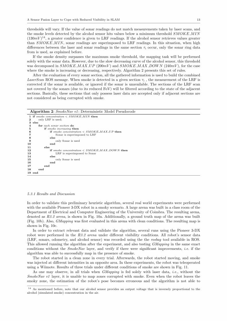
If the smoke density surpasses the maximum smoke threshold, the mapping task will be performedsolely with the sonar data. However, due to the slow decreasing curve of the alcohol sensor, this thresholdwas decomposed in SMOKE MAX UP (200mV ) and SMOKE MAX DOWN (240mV ), for the casewhere the smoke is increasing or decreasing, respectively. Algorithm 2 presents this set of rules.
After the evaluation of every sonar section, all the gathered information is used to build the combinedLaserScan ROS message. When smoke is detected in a given section τi , the measurement of the LRF iscorrected if the sonar is available, or ignored if the sonar is unavailable. The sections of the LRF scannot covered by the sonars (due to its reduced FoV) will be filtered according to the state of the adjacentsections. Basically, these sections that only possess laser data are accepted only if adjacent sections arenot considered as being corrupted with smoke.
Algorithm 2: SmokeNav v1 : Deterministic Model Pseudocodeif smoke concentration < SMOKE MIN then1
only LRF is used;2else3
for each sonar section do4if smoke increasing then5
if smoke concentration < SMOKE MAX UP then6Sonar is superimposed to LRF7
else8only Sonar is used9
end10
else11if smoke concentration < SMOKE MAX DOWN then12
LRF is superimposed to Sonar13else14
only Sonar is used15end16
end17
end18
end19
5.3.1 Results and Discussion
In order to validate this preliminary heuristic algorithm, several real world experiments were performedwith the available Pioneer 3-DX robot in a smoky scenario. A large arena was built in a class room of theDepartment of Electrical and Computer Engineering of the University of Coimbra. The resulting arena,denoted as R3.2 arena, is shown in Fig. 10a. Additionally, a ground truth map of the arena was built(Fig. 10b). Also, GMapping was first evaluated in this arena with clean conditions. The resulting map isshown in Fig. 10c.
In order to extract relevant data and validate the algorithm, several runs using the Pioneer 3-DXrobot were performed in the R3.2 arena under different visibility conditions. All robot’s sensor data(LRF, sonars, odometry, and alcohol sensor) was recorded using the the rosbag tool available in ROS.This allowed running the algorithm after the experiment, and also testing GMapping in the same exactconditions without the SmokeNav layer, and verify if there were significant improvements, i.e. if thealgorithm was able to successfully map in the presence of smoke.
The robot started in a clean zone in every trial. Afterwards, the robot started moving, and smokewas injected at different intensities in an opposite area. In these experiments, the robot was teleoperatedusing a Wiimote. Results of three trials under different conditions of smoke are shown in Fig. 11.
As one may observe, in all trials when GMapping is fed solely with laser data, i.e., without theSmokeNav v1 layer, it is unable to map zones corrupted with smoke. Even when the robot leaves thesmoky zone, the estimation of the robot’s pose becomes erroneous and the algorithm is not able to
14 As mentioned before, note that our alcohol sensor provides an output voltage that is inversely proportional to thealcohol (simulated smoke) concentration in the air.

14 Joao Machado Santos et al.
(a) Photo of the arena. (b) Ground truth map.
(c) Photo of the smoky conditions in the arena. (d) Resulting map of a run with Gmapping.
Fig. 10: The R3.2 arena with dimensions: 13.63 × 9.87 meters. The arrow in Fig. 10b represents theviewpoint of Fig. 10a
correctly recover and update the pose. This is expected since the algorithm is only using the LRF andthe scan matching process fails due to the false readings.
From the analysis of the results, it can be seen that the first sensor fusion algorithm proposed wasable to map the arena even when the smoke density was high. However, when the switching from theLRF to sonars occurred, the quality of the map drastically decreased, as expected. This happened notonly because of the low resolution of the sonars, but also due to their previously mentioned misbehavior.This is verified in Figures 11a and 11b, where the robot crossed regions with a higher density of smoke,moments after the beginning of the mapping task. In the remaining trials, the smoke was injected onlyin the latest region to be mapped. For this reason, GMapping using only LRF data did not performas poorly as one could expect. Nevertheless, in the second and third trials, the impact of smoke in themapping task is visible: the upper left corner was not correctly mapped. Due to the high smoke density,the scans returned by the LRF resemble a dense obstacle in that area. However, when GMapping wasfed with sonar data, that zone was eventually mapped, though the quality of the mapping was low.
From the analysis of the results, it was concluded that this preliminary approach has several weaknessesand is not robust enough for harsh conditions. The behavior of the sonar ring is erroneous and not stableenough. Most of the times, the SLAM algorithm is relying only on the readings provided by the sonars,which does not provide enough data for localization. Also, the quality of the obtained maps is low. In thenext section, we present a novel multi-sensor fusion approach based on fuzzy logic aiming to overcomesome of these issues.
5.4 SmokeNav v2 : Fuzzified Model
The method presented in the previous subsection revealed that it is possible to map an environment underlow visibility conditions using only commercial off-the-shelf sensors. However, the obtained results were

A Sensor Fusion Layer to Cope with Reduced Visibility in SLAM 15
(a) Trial 1: GMapping only with LRF data. (b) Trial 1: GMapping with the SmokeNav v1layer.
(c) Trial 2: GMapping only with LRF data. (d) Trial 2: GMapping with the SmokeNav v1layer.
(e) Trial 3: GMapping only with LRF data. (f) Trial 3: GMapping with the SmokeNav v1layer.
Fig. 11: Results of three trials. Left images are the resulting maps from GMapping only with LRF dataand the right images are the maps obtained using the preliminary multimodal sensor fusion technique.
bellow expectations and far from being applicable under real world situations. The need to improve themethod arose and this section presents a newer, more robust, and more elaborated version. Additionally,we chose to use the Nomad Scout robot, which was available at this stage of the work, taking advantageof its more reliable sonar ring, as it was discussed in sec. 4.
In order to overcome the limitations of the deterministic approach described in the previous section, wedeveloped an adaptive fuzzy logic system to handle the sensing information arising from the sonars, LRF,and alcohol sensor, by following a similar approach to our previous work in another domain [29]. Thiswas the base for the development of the SmokeNav v2 layer. Other proposals with different formalism tomultimodal sensor fusion, such as Bayesian decision analysis [30], could be adopted as well. The successfuldevelopment of a fuzzy model is a complex multi-step process, in which the designer is faced with a largenumber of alternative implementation strategies and attributes [31].
In sum, based on the information extracted from the inputs, namely the alcohol sensor, sonar andLRF readings, the fuzzy logic system can infer normalized confidence measures, which can be used to

16 Joao Machado Santos et al.
Something to eventually put in the intro: Robots’ perception can significantly benefit from merging sensing information from different sources. This paper proposes a
fuzzified multi-sensor fusion between sonars, laser and alcohol sensor, so as to overcome the lack of visibility and noise induced by smoke particles. The output of the fuzzy system corresponds to a normalized trust measure, i.e., probability, for each sonar reading and corresponding section of the laser.
Something to put in the methodology: This work benefits from fuzzy logic to handle the sensing information arising from the sonars, laser and alcohol sensor [1, 2].
Other proposals with different formalism to multi-sensor fusion, such as Bayesian decision analysis, could be adopted as well [3] [4]. Nevertheless, fuzzy logic addresses such applications perfectly as it resembles human decision making with an ability to generate precise solutions from certain or approximate information. The successful development of a fuzzy model is a complex multi-step process, in which the designer is faced with a large number of alternative implementation strategies and attributes [5, 6].
In sum, based on the information extracted from the inputs, namely the alcohol sensor, sonar and laser readings, the fuzzy logic system can infer normalized trust measures, which can be used to decide on whether to choose the sonar or the laser (Fig. 1). These two outputs can be perceived as the probability on trusting on a given sonar reading (𝜌𝜌𝑆𝑆) or the probability on trusting on the laser readings within the same section of that sonar (𝜌𝜌𝐿𝐿). It is noteworthy that these probability measures are not mutually exclusive. In other words, it is possible to reject the readings provided by both sources, e.g., a high intensity of smoke detected by the alcohol sensor and a sonar reading above 2.5 meters is likely to result in probabilities on trusting on either sources near zero. In these cases, GMapping will be fed with the predefined value of maxUrange (Table I), thus considering it as a saturated reading.
The control architecture presented in Fig. 1 is executed at each iteration 𝑡𝑡, and for each section 𝜏𝜏 (Fig. 5), thus returning the probability of accepting the sonar 𝜏𝜏 at time 𝑡𝑡, 𝜌𝜌𝑆𝑆(𝜏𝜏, 𝑡𝑡), and the probability of accepting the laser readings from section 𝜏𝜏 at time 𝑡𝑡, 𝜌𝜌𝐿𝐿(𝜏𝜏, 𝑡𝑡). The inputs of the fuzzy system comprise the sonar reading from section𝜏𝜏,𝑠𝑠𝑅𝑅[𝜏𝜏, 𝑡𝑡] the alcohol sensor reading,𝑎𝑎𝑅𝑅[𝑡𝑡] and the standard deviation of laser readings, 𝜎𝜎(𝑙𝑙𝑅𝑅[𝑡𝑡]). The later was chosen to improve the decision mainly due to the alcohol sensor limitations previously described. By monitoring the standard deviation of the laser readings, it is possible to observe that the standard deviation of the laser readings significantly drops when affected by the smoke (Fig. 2). This is an expected behavior since the smoke tends to uniformly constrain the readings. Although experiments were carried out by considering the standard deviation, any other measure of dispersion or correlation could had been used.
Fig. 1. Fuzzy logic system to infer the adequate reading.
OUTPUT
INPUTS
𝑠𝑠𝑅𝑅[𝜏𝜏, 𝑡𝑡]
𝑎𝑎𝑅𝑅[𝑡𝑡]
𝜎𝜎(𝑙𝑙𝑅𝑅[𝑡𝑡])
FUZZY LOGIC SYSTEM
𝜌𝜌𝑆𝑆(𝜏𝜏, 𝑡𝑡) Fuzzifier 𝜇𝜇𝑠𝑠𝑅𝑅(𝑠𝑠𝑅𝑅[𝜏𝜏, 𝑡𝑡])
Rules
Fuzzifier 𝜇𝜇𝑎𝑎𝑅𝑅(𝑎𝑎𝑅𝑅[𝑡𝑡])
Fuzzifier 𝜇𝜇𝑙𝑙𝑅𝑅(𝜎𝜎(𝑙𝑙𝑅𝑅[𝑡𝑡]))
Inference Defuzzifier
𝜌𝜌𝐿𝐿(𝜏𝜏, 𝑡𝑡)
Fig. 12: Fuzzy logic system to choose the adequate reading.
Fig. 2. Top: Alcohol sensor readings over time 𝑎𝑎𝑅𝑅[𝑡𝑡]. Bottom: Standard deviation of the laser readings over time 𝑆𝑆𝑆𝑆𝑆𝑆(𝑙𝑙𝑅𝑅[𝑡𝑡]). As one may observe, the alcohol sensor presents significant variations when facing smoke. However, it also presents a slow response, either when the robot finds the smoke, or when it is able to overcome it. On the other hand, although more noisy, the standard deviation of the laser readings proves to be a relevant complement to the decision-making.
As Fig. 1 depicts, the overall organization of this architecture resembles the commonly used feedback controllers wherein contextual knowledge is extracted from data, followed by a reasoning phase to provide the adequate information to the robot (i.e., map and localization). Hence, based on the alcohol sensor, the sonars and the laser, one can assess the relation between the inputsand outputs of the fuzzy system. The choice around this relation depends on the characteristics of the readings arising from each source.
Considering the characteristics of the sensors previously highlighted and by observing Fig. 2, one can outline a considerably vague or imprecise rationale: “The laser readings may only be trusted when alcohol readings are below 20 or the standard deviation of the laser readings is above 0.8. If not, only trust the sonar readings whenever it presents readings inferior to 2.5 meters”.
Although the input information to the system may be imprecise, the results of fuzzy analysis are not [6]. Fuzzy sets needmembership functions, i.e., mathematical equations that can take certain shapes. Examples of reasonable functions are Π-shaped and bell-shaped functions, because of their simplicity and efficiency when considering computational issues. In spite of this, and considering the above rationale, the following Π-shaped membership rules were defined (Fig. 3).
The membership function 𝜇𝜇𝑠𝑠𝑅𝑅(𝑠𝑠𝑅𝑅[𝜎𝜎, 𝑡𝑡]) represents how Confident the sonar is. The membership function 𝜇𝜇𝑎𝑎𝑅𝑅(𝑎𝑎𝑅𝑅[𝑡𝑡]) represents how Alcoholized the environment is. The membership function 𝜇𝜇𝑙𝑙𝑅𝑅(𝑆𝑆𝑆𝑆𝑆𝑆(𝑙𝑙𝑅𝑅[𝑡𝑡])) represents how Dense the smoke is.
0 50 100 150 200 250 300 3500
20
40
60
80
100
time (sec)
a R[t]
0 50 100 150 200 250 300 3500
0.5
1
1.5
2
time (sec)
σ(l R
[t])
smoke
Fig. 13: Sensor readings over time: on the top, alcohol sensor readings, aR[t], over time; on the bottom,standard deviation, σ(lR[t]), of the LRF readings over time. The alcohol sensor presents significant vari-ations when facing smoke. However, it also presents a slow response. On the other hand, the standarddeviation of the laser readings proves to be a relevant complement to the decision-making.
decide on whether to choose the sonars or the LRF data (Fig. 12). These two outputs can be perceivedas the confidence on a given sonar reading (ρS) or the probability on trusting on the laser readingswithin the same section τi of that sonar (ρL). It is noteworthy that these probability measures are notmutually exclusive. In other words, it is possible to reject the readings provided by both sources, e.g. ahigh intensity of smoke detected by the alcohol sensor and a sonar reading above 2.5 meters is likely toresult in probabilities on trusting in both sources near to zero. In these cases, GMapping will be fed witha value greater than the maximum range of the sensor, thus considering it as a saturated reading.
The control architecture presented in Fig. 12 is executed at each iteration t, and for each section τ(Fig. 9), thus returning the probability of accepting the sonar τ at time t, ρS(τ, t), and the probabilityof accepting the LRF readings from the same section at time t, ρL(τ, t). The inputs of the fuzzy systemcomprise the sonar reading from section τ , sR[τ, t], the alcohol sensor reading, aR[t], and the standarddeviation of LRF readings, σ(lR[t]). The latter was chosen to improve the decision mainly due to thealcohol sensor limitations previously described. By monitoring the standard deviation of the LRF readings,it is possible to observe that their standard deviation significantly drops when affected by the smoke (Fig.13). This is an expected behavior since the smoke tends to uniformly constrain the readings. Althoughwe have considered the standard deviation of readings in our experiments, other measures of dispersionor correlation could be used instead.
As Fig. 12 depicts, the overall organization of this architecture resembles the commonly used feedbackcontrollers wherein contextual knowledge is extracted from data, followed by a reasoning phase to providethe adequate information to the robot (i.e. map and localization). Hence, based on the alcohol sensor,the sonars and the LRF, one can assess the relation between the inputs and outputs of the fuzzy system.The choice around this relation depends on the characteristics of the readings arising from each source.
Considering the characteristics of the sensors previously highlighted and by observing Fig. 13, onecan outline a considerably vague or fuzzy rationale: “The LRF readings can only be trusted when alcoholreadings are below 20 or the standard deviation of the laser readings is above 0.8. If not, only trust thesonar readings whenever it presents readings inferior to 2.5 meters”.

A Sensor Fusion Layer to Cope with Reduced Visibility in SLAM 17
Fig. 3. Membership function for each input and to quantify the consequents. Top-left: Input sonar reading from section 𝜎𝜎, 𝜇𝜇𝑠𝑠𝑅𝑅(𝑠𝑠𝑅𝑅[𝜏𝜏, 𝑡𝑡]); Top-right: Input alcohol sensor reading, 𝜇𝜇𝑎𝑎𝑅𝑅(𝑎𝑎𝑅𝑅[𝑡𝑡]); Bottom-left: Input standard deviation of laser readings, 𝜇𝜇𝑙𝑙𝑅𝑅(𝑆𝑆𝑆𝑆𝑆𝑆(𝑙𝑙𝑅𝑅[𝑡𝑡])); Bottom-right: Output probabilities 𝜌𝜌𝑆𝑆(𝜏𝜏, 𝑡𝑡) and 𝜌𝜌𝐿𝐿(𝜏𝜏, 𝑡𝑡).
The Mamdani-Minimum was used to quantify the premise and implication. The defuzzification was performed using the center-
of-gravity (CoG) method. The CoG is a continuous method and one of the most frequently used in control engineering and process modeling being represented by the centroid of the composite area of the output fuzzy term.
Considering the above rationale and figures, the following diffuse IF-THEN-ELSE rules (cf., [7]) are considered:
IF 𝑎𝑎𝑅𝑅[𝑡𝑡] IS Alcoholized OR 𝑆𝑆𝑆𝑆𝑆𝑆(𝑙𝑙𝑅𝑅[𝑡𝑡]) IS Dense THEN 𝜌𝜌𝐿𝐿(𝜏𝜏, 𝑡𝑡) IS Laser-driven ELSE-IF 𝑠𝑠𝑅𝑅[𝜏𝜏, 𝑡𝑡] IS Confident THEN 𝜌𝜌𝑆𝑆(𝜏𝜏, 𝑡𝑡) IS Sonar-driven
The decision on whether to choose the sonar or the laser, at a given section 𝜏𝜏 and time 𝑡𝑡, is then evaluated by simply comparing
which one has a higher trust probability and if that trust probability is equal or superior to a given threshold. For instance, one will choose the sonar 𝜏𝜏 at time 𝑡𝑡 over the laser readings within the same section if 𝜌𝜌𝑆𝑆(𝜏𝜏, 𝑡𝑡) > 𝜌𝜌𝐿𝐿(𝜏𝜏, 𝑡𝑡) and 𝜌𝜌𝑆𝑆(𝜏𝜏, 𝑡𝑡) > 𝜌𝜌𝑇𝑇. In this work, we consider the threshold to be the expected value of a random probabilistic distribution, i.e., 𝜌𝜌𝑇𝑇 = 1
2.
References [1] L. A. Zadeh, "Fuzzy Sets," Information and Control, vol. 8, no. 3, pp. 338-353, 1965. [2] M. S. Couceiro, J. A. T. Machado, R. P. Rocha and N. M. F. Ferreira, "A Fuzzified Systematic Adjustment of the Robotic
Darwinian PSO," Robotics and Autonomous Systems, vol. 60, no. 12, pp. 1625-1639, 2012. [3] R. M. Turner, "Context-mediated behavior for intelligent agents," International Journal of Human-Computer Studies, vol. 48,
pp. 307-330, 1998.
0 1 2 3 4 5 6 70
0.1
0.2
0.3
0.4
0.5
0.6
0.7
0.8
0.9
1
0 50 100 150 200 2500
0.1
0.2
0.3
0.4
0.5
0.6
0.7
0.8
0.9
1
0 0.5 1 1.5 2 2.5 30
0.1
0.2
0.3
0.4
0.5
0.6
0.7
0.8
0.9
1
0 0.2 0.4 0.6 0.8 10
0.1
0.2
0.3
0.4
0.5
0.6
0.7
0.8
0.9
1
𝑠𝑠𝑅𝑅[𝜏𝜏, 𝑡𝑡]
𝜎𝜎(𝑙𝑙𝑅𝑅[𝑡𝑡])
𝑎𝑎𝑅𝑅[𝑡𝑡]
Confident Alcoholized
Dense
𝜌𝜌𝑆𝑆(𝜏𝜏, 𝑡𝑡), 𝜌𝜌𝐿𝐿(𝜏𝜏, 𝑡𝑡)
Sonar-driven, Laser-driven
𝜇𝜇𝑠𝑠𝑅𝑅(𝑠𝑠𝑅𝑅[𝜏𝜏, 𝑡𝑡]) =
⎩⎪⎨
⎪⎧
1 , 𝑠𝑠𝑅𝑅[𝜏𝜏, 𝑡𝑡] < 1
1 − 2 �𝑠𝑠𝑅𝑅[𝜏𝜏,𝑡𝑡]−12.5−1
�2
, 1 ≤ 𝑠𝑠𝑅𝑅[𝜏𝜏, 𝑡𝑡] < 1.75
2 �𝑠𝑠𝑅𝑅[𝜏𝜏,𝑡𝑡]−2.52.5−1
�2
, 1.75 ≤ 𝑠𝑠𝑅𝑅[𝜏𝜏, 𝑡𝑡] < 2.50 , 𝑠𝑠𝑅𝑅[𝜏𝜏, 𝑡𝑡] ≥ 2.5
𝜇𝜇𝑎𝑎𝑅𝑅(𝑎𝑎𝑅𝑅[𝑡𝑡]) =
⎩⎪⎨
⎪⎧
0 , 𝑎𝑎𝑅𝑅[𝑡𝑡] < 25
2 �𝑎𝑎𝑅𝑅[𝑡𝑡]−2565−25
�2
, 25 ≤ 𝑎𝑎𝑅𝑅[𝑡𝑡] < 45
1 − 2 �𝑎𝑎𝑅𝑅[𝑡𝑡]−6565−25
�2
, 45 ≤ 𝑎𝑎𝑅𝑅[𝑡𝑡] < 651 , 𝑎𝑎𝑅𝑅[𝑡𝑡] ≥ 65
𝜇𝜇𝑙𝑙𝑅𝑅(𝜎𝜎(𝑙𝑙𝑅𝑅[𝑡𝑡])) =
⎩⎪⎨
⎪⎧
0 , 𝜎𝜎(𝑙𝑙𝑅𝑅[𝑡𝑡]) < 0.8
2 �𝜎𝜎(𝑙𝑙𝑅𝑅[𝑡𝑡])−0.81.2−0.8
�2
, 0.8 ≤ 𝜎𝜎(𝑙𝑙𝑅𝑅[𝑡𝑡]) < 1
1 − 2 �𝜎𝜎(𝑙𝑙𝑅𝑅[𝑡𝑡])−1.21.2−0.8
�2
, 1 ≤ 𝜎𝜎(𝑙𝑙𝑅𝑅[𝑡𝑡]) < 1.21 , 𝜎𝜎(𝑙𝑙𝑅𝑅[𝑡𝑡]) ≥ 1.2
𝜇𝜇𝜌𝜌𝑆𝑆�𝜌𝜌𝑆𝑆(𝜏𝜏, 𝑡𝑡)� = 𝜇𝜇𝜌𝜌𝐿𝐿�𝜌𝜌𝐿𝐿(𝜏𝜏, 𝑡𝑡)� =1
1+�𝜌𝜌𝑋𝑋(𝜏𝜏,𝑡𝑡)−10.25 �
5 ,𝑋𝑋 = {𝑆𝑆, 𝐿𝐿}
Fig. 14: Membership function for each input and to quantify the consequents: on the top-left, inputsonar reading from section τ , µsR(sR[τ, t]); on the top-right, input alcohol sensor reading, µaR
(aR[t]); onthe bottom-left, input standard deviation of laser readings, µlR(σ(lR[t])); on the bottom-right, outputprobabilities ρS(τ, t) and ρL(τ, t).
Although the input information of the system might be imprecise, the results of fuzzy analysis arenot. Fuzzy sets need membership functions, i.e. mathematical equations that can take certain shapes [31].Examples of reasonable functions are Π-shaped and bell-shaped functions, because of their simplicity andefficiency when considering computational issues. In spite of this, and considering the above rationale,the membership rules represented in Fig. 14 and described below were defined.
The membership function µsR(sR[τ, t]) represents how Confident the sonar is. The membership func-tion µaR
(aR[t]) represents how Alcoholized the environment is. The membership function µlR(σ(lR[t]))represents how Dense the smoke is.
As for the consequent functions, one can simply define the same bell-shaped membership relation forsoftening both outputs, as represented in Fig. 14. The Mamdani-Minimum [31] was used to quantify thepremise and implication. The defuzzification was performed using the center-of-gravity (CoG) method.The CoG is a continuous method and one of the most frequently used in control engineering and processmodeling, being represented by the centroid of the composite area of the output fuzzy term.
Considering the above rationale and figures, the following diffuse IF-THEN-ELSE rules are consid-ered in Algorithm 3.
Algorithm 3: SmokeNav v2 : Fuzzified Model Pseudocode
1: if aR[t] is Alchoholized or σ(lR[t]) is Dense then2: ρL(τ, t) is Laser-driven3: else if SR[τ, t] is Confident then4: ρ(τ, t) is Sonar-driven5: end if

18 Joao Machado Santos et al.
Initial PointSource ofSmoke
Fig. 15: The modified R3.2 arena.
The decision on whether to choose the sonar or the LRF at a given section τ and time t is thenevaluated by simply comparing which one has a higher trust probability and if that trust probability isequal or greater than a given threshold. For instance, one will choose the sonar at time t over the LRFreadings within the same section if ρS(τ, t) > ρL(τ, t) and ρS(τ, t) > ρT . In this work, we consider thethreshold to be the expected value of an uniform probability distribution with sample space between 0and 1, i.e., ρT = 1
2 .
5.4.1 Results and Discussion
Several experiments with the Scout mobile robot (see Fig. 2b, page 7) in a realistic scenario were performedto validate the SmokeNav v2 layer using fuzzy logic. A modified test arena was built in the same classroom used in the experiments reported in section 5.3.1. Additionally, a run with GMapping on the NomadScout in this arena with clean conditions was conducted. The resulting map is shown in Fig. 15. In thisnew version, the Nomad Scout was available, and it was chosen due to the superior performance of thesonar ring when compared to the Pioneer 3-DX, as seen in section 4. As mentioned before, the sonar ringof Scout robot behaves better in most of the situations. For example, in the case of plain corridor, thesonar ring of this robot is able to retrieve more information than the Pioneer’s sonar ring.
During these experiments, the same test procedure described in subsection 5.3.1 was considered toevalute the fuzzified approach against one which exclusively uses LRF readings. As before, even whenthe robot leaves the smoky region, the estimation of the robot’s pose using only LRF data becomeserroneous and the SLAM algorithm is not able to correctly recover and update the robot’s pose. This isnot surprising since the algorithm is only using the LRF readings and the scan matching process failsdue to the false readings.
From the analysis of the results shown in Fig. 16, it can be seen that the proposed fuzzy techniqueallowed to successfully map the arena in most cases. The poor results obtained in the third trial arejustified by the higher density of smoke during all the experiment, which was an extreme case. To supportthe results, the metric used in section 3 to evaluate the performance of different SLAM approaches wasused. The resulting error for each trial is shown in Table 4. Also, the usage of sonar data was evaluatedby counting the time that sonar data was used along the experiments.
The improvements are significant and it has been shown that SLAM in such harsh conditions ispossible using commonly available range sensors in mobile robots and the fuzzified multimodal sensorfusion approach proposed herein. In addition, the developed layer does not introduce significant delays inthe system, being adequate for use in real-time. The solution proposed is affordable, using only commercialoff-the-shelf (COTS) and fairly cheap sensors. Superior results would be obtained using sonars with morestable readings. Beyond that, it is the authors’ belief that a solution based on a radar sensor (instead ofsonars) would be more effective, even though much more expensive, to solve the problem while maintainingmaps of high quality, regardless the smoke density in the environment.

A Sensor Fusion Layer to Cope with Reduced Visibility in SLAM 19
(a) Trial 1: GMapping only with LRFdata.
(b) Trial 2: GMapping only with LRFdata.
(c) Trial 3: GMapping only with LRFdata.
(d) Trial 1: GMapping with the Smo-keNav v2 layer.
(e) Trial 2: GMapping with the Smo-keNav v2 layer.
(f) Trial 3: GMapping with the Smo-keNav v2 layer.
Fig. 16: Results of three trials. Top images are the resulting maps from GMapping only with LRF dataand the bottom images are the maps obtained using the SmokeNav layer v2.
Table 4: Error estimation for each trial.
Trial SmokeNav Layer LRF data Sonar Usage1 2.69 18.02 23.33%2 10.14 19.07 40.25%3 15.83 23.33 21.53%
6 Conclusion
In this work, a sensor fusion layer for SLAM in low visibility scenarios was proposed. It was verified in thedevelopment of the method that the information obtained using only the available two sensory modalitieswas insufficient in more extreme situations, and we made use of an additional sensor to assess smokedensity. A preliminary heuristic version of this technique was presented and the results were discussed.This was fundamental to understand which challenges must be overcome, but also to learn the real impactof the low visibility conditions on mapping tasks. The results obtained are insufficient for a real worldapplication, but mostly because of hardware issues. Despite that, we figured that with the correct choiceof ranging sensors it is possible to achieve mapping tasks in adverse conditions.
A second version of sensor fusion layer was proposed in order to overcome the limitations of thepreliminary approach. The proposed fuzzified multimodal sensor fusion technique makes use of multipleCOTS sensors in order to successfully map environments corrupted by smoke, dust, or steam particles.It is a simple and easily adaptable approach that can be potentially applied with different LRF-basedSLAM algorithms, simply by replacing the GMapping layer with another algorithm. Experimental resultsusing a Particle Filter 2D SLAM approach proved its functionality. However, hardware limitations still

20 Joao Machado Santos et al.
have and important impact on the results, which are comprehensibly not optimal. Still, it was proved thatusing the complementary characteristics of multiple range sensors, it is possible to surpass this reducedvisibility situation and benefit from the advantages of the distinct range sensors.
Some issues are still left open and correspond to future guidelines that can be followed to improvethe current work. Replacing the sonar ring by a range sensor, also immune to smoke but with higherresolution (e.g. a UWB radar), would greatly improve the results. The integration of a visual camera toprovide a method to detect smoke in the FoV of the LRF, by measuring the gray intensity in the image,could also be explored. Even though the visual camera is highly disturbed by lightning conditions, itcan provide richer information about the environment. It would be also interesting to integrate all thesechanges and validate them through several scenarios with different conditions and more “realistic” smoke.Additionally, an IMU can be integrated in order to increase the accuracy of the localization technique,when sonars and odometry are the only sensors providing valid readings to the robot. At last, and giventhe modularity of the herein proposed approach, a benchmark of several SLAM methods shall be carriedour in order to assess the most fitted combination to be used in scenarios with reduced visibility.
Acknowledgements This work was supported by the CHOPIN research project (PTDC/EEA-CRO/119000/2010) fundedby Fundacao para a Ciencia e a Tecnologia (FCT). In its final stage, the first author was also supported by the EU ICTSTRANDS project 600623. The authors would like to thank Prof. Helder Araujo from ISR-Coimbra for providing the Scoutmobile robot used in some of the experiments.
References
1. H. Durrant-Whyte and T. Bailey, “Simultaneous Localization and Mapping: Part I,” IEEE Robotics and AutomationMagazine, vol. 13, no. 2, pp. 99-110 (2006).
2. F. Ferreira, I. Amorim, R. Rocha, and J. Dias, “T-SLAM: Registering Topological and Geometric Maps for RobotLocalization in Large Environments,” in H. Hahn, H. Ko, and S. Lee (eds.), Multisensor Fusion and Integration forIntelligent Systems, Springer, pp. 423-438 (2009).
3. M. Lazaro, L. Paz, P. Pinies, J. Castellanos, and G. Grisetti, “Multi-Robot SLAM Using Condensed Measurements,” in2013 IEEE/RSJ International Conference on Intelligent Robots and Systems, Tokyo, Japan, pp. 1069-1076 (2013).
4. R. P. Rocha, D. Portugal, M. S. Couceiro, F. Araujo, P. Menezes, and J. Lobo, “The CHOPIN project: Cooperationbetween Human and rObotic teams in catastroPhic INcidents,” in IEEE 13th International Symposium on Safety, Securityand Rescue Robotics, Linkoping, Sweden (2013).
5. S. Thrun., W. Burgard, D. Fox., “Probabilistic Robotics,” MIT Press (2005).6. S. J. Julier, J.K. Uhlmann, “A counter example to the theory of simultaneous localization and map building,” Robotics
and Automation, 2001. Proceedings 2001 ICRA. IEEE International Conference on , vol.4, no., pp. 4238-4243, 2001.7. M. Montemerlo, S. Thrun, D. Koller, B. Wegbreit, “FastSLAM: A Factored Solution to the Simultaneous Localization
and Mapping Problem,” in AAAI National Conference on Artificial Intelligence, Edmonton, Canada (2002).8. G. Dissanayake, P. Newman, S. Clark, H. F. Durrant-Whyte, M. Csorba, “A Solution to the Simultaneous Localization
and Map Building (SLAM) Problem,” in IEEE Transactions on Robotics and Automation, vol. 17, no. 3, pp. 229-241(2001).
9. S. Huang, G. Dissanayake., “Convergence and Consistency Analysis for Extended Kalman Filter Based SLAM,” in IEEETransactions on Robotics, vol. 23, no. 5, pp. 1036-1049 (2007).
10. G. Grisetti, C. Stachniss, W. Burgard, “Improved Techniques for Grid Mapping With Rao-Blackwellized ParticleFilters,” in Transactions on Robotics, vol. 23, no. 1, pp. 34-46 (2007).
11. F. Lu, E. Milios, “Globally Consistent Range Scan Alignment for Environment Mapping,” in Autonomous Robots, vol.4, no. 4 , pp. 333-349 (1997).
12. P. Agarwal, G.D. Tipaldi, L. Spinello, C. Stachniss, W. Burgard, “Robust Map Optimization using Dynamic CovarianceScaling,” in 2013 IEEE International Conference on Robotics and Automation, Karlsruhe, Germany, pp. 62-69 (2013).
13. S. Kohlbrecher, J. Meyer, O. Von Stryk, U. Klingauf, “A Flexible and Scalable SLAM System with Full 3D MotionEstimation,” in 11th IEEE International Symposium on Safety, Security and Rescue Robotics, Kyoto, Japan, (2011).
14. E. Pedrosa, N. Lau, A. Pereira, “Online SLAM Based on a Fast Scan-Matching Algorithm,” in L. Correia, L. P. Reis,J. Cascalho (eds.), Progress in Artificial Intelligence, Lecture Notes in Computer Science, vol. 8154, pp. 295-306, Springer(2013).
15. C. Brunner, T. Peynot, and T. Vidal-Calleja, “Automatic Selection of Sensor Modality for Resilient Localisation inLow Visibility Conditions,” in 2012 Robotics: Science and Systems, Workshop on Beyond laser and vision: Alternativesensing techniques for robotic perception, Sydney, Australia (2012).
16. T. Deissler and J. Thielecke, “UWB SLAM with Rao-Blackwellized Monte Carlo data association,” in InternationalConference on Indoor Positioning and Indoor Navigation, Zurich, Switzerland, pp. 1-5 (2010).
17. M. Castro and T. Peynot, “Laser-to-radar sensing redundancy for resilient perception in adverse environmental condi-tions,” in Australasian Conference on Robotics and Automation, Sydney, Australia (2012).
18. J. Sales, R. Marın, E. Cervera, S. Rodrıguez, and J. Perez, “Multi-Sensor Person Following in Low-Visibility Scenarios,”Sensors, vol. 10, no. 12, pp. 10953-10966 (2010).
19. J. Marti, J. Sales, R. Marın, and P. Sanz, “Multi-Sensor Localization and Navigation for Remote Manipulation inSmoky Areas,” in International Journal of Advanced Robotic Systems, vol. 10, no. 211 (2011).
20. J. Pascoal, L. Marques, and A. De Almeida, “Assessment of Laser Range Finders in Risky Environments,” in 2008IEEE/RSJ International Conference on Intelligent Robots and Systems, Nice, France, pp. 3533-3538 (2008).
21. V. Tretyakov and T. Linder, “Range Sensors Evaluation under Smoky Conditions for Robotics Applications,” in 11thIEEE International Symposium on Safety, Security, and Rescue Robotics, Kyoto, Japan, pp. 215-220 (2011).

A Sensor Fusion Layer to Cope with Reduced Visibility in SLAM 21
22. F. Pomerleau, A. Breitenmoser, M. Liu, F. Colas, and R. Siegwart, “Noise Characterization of Depth Sensors for SurfaceInspections,” in 2012 2nd International Conference on Applied Robotics for the Power Industry, Zurich, Switzerland, pp.16-21 (2012).
23. B. Steux, and O. El Hamzaoui, “tinySLAM: a SLAM Algorithm in Less than 200 Lines C-Language Program,” in 201011th International Conference on Control Automation Robotics & Vision, Singapore, pp. 1975-1979 (2010).
24. L. Carlone, R. Aragues, J. A. Castellanos, and B. Bona, “A Linear Approximation for Graph-based SimultaneousLocalization and Mapping,” in Robotics: Science and Systems, Los Angeles, California, USA (2011).
25. R. Vincent, B. Limketkai, and M. Eriksen, “Comparison of Indoor Robot Localization Techniques in the Absence ofGPS,” in SPIE 7664, Detection and Sensing of Mines, Explosive Objects, and Obscured Targets XV, 76641Z (2010).
26. J. Machado Santos, D. Portugal, and R. P. Rocha, “An Evaluation of 2D SLAM Techniques Available in RobotOperating System,” in IEEE 13th International Symposium on Safety, Security and Rescue Robotics, Linkoping, Sweden(2013).
27. M. Quigley, K. Conley, B. P. Gerkey, J. Faust, T. Foote, J. Leibs, R. Wheeler, and A. Y. Ng, “ROS: an Open-SourceRobot Operating System,” in 2009 IEEE International Conference on Robotics and Automation, Workshop on OpenSource Software, Kobe, Japan (2009).
28. G. Grisetti, C. Stachniss, and W. Burgard, “Improved Techniques for Grid Mapping With Rao-Blackwellized ParticleFilters,” IEEE Transactions on Robotics, vol. 23, no. 1, pp. 34-46 (2007).
29. M. S. Couceiro, J. T. Machado, R. P. Rocha, and N. M. Ferreira, “A Fuzzified Systematic Adjustment of the RoboticDarwinian PSO,” Robotics and Autonomous Systems, vol. 60, no. 12, pp. 1625-1639 (2012).
30. J. F. Ferreira, and J. Dias, “Probabilistic Approaches to Robotic Perception,” Springer Tracts in Advanced Robotics,Vol. 91 (2014).
31. L.A. Zadeh, “Fuzzy Sets, Information and Control,” Information and Control, vol. 8, no. 3, pp. 338-353 (1965).