copyright carnegie mellon robotics academy all rights reserved radio frequency in this lesson you...
TRANSCRIPT

Copyright Carnegie Mellon Robotics Academy all rights reserved
Radio Frequency
• In this lesson you will learn:– The relationship between (RF) transmitters
and receivers– Resonance - the underlying scientific factor
that allows the precise transmission frequency of a signal
– Engineering notation
Copyright Carnegie Mellon Robotics Academy all rights reserved
The Kettledrum
• If a trumpet, and a kettledrum tuned to the note of “E”, were placed in the same room when the trumpet were played the “E” note the sound wave would leave the trumpet and travel through the air. The air molecules would then vibrate against the surface of the drum and the drum would vibrate with an audible sound.

Copyright Carnegie Mellon Robotics Academy all rights reserved
What is resonance?
• Resonance is the induction on a physical object of vibrations by a vibrating force having the same frequency.
A dramatic example of resonance is demonstrated by the Tacoma Narrows Bridge disaster. Click “Background/Slide Shows/Tacoma Bridge: Example of Resonance” to see the video.

Copyright Carnegie Mellon Robotics Academy all rights reserved
New terms
• Crystal - An electronic device, such as an oscillator or detector, using such a material.
• Oscillator – To oscillate means to swing back and forth with a steady, uninterrupted rhythm. An oscillator is a device or mechanism for producing or controlling oscillations; especially : one (as a radiofrequency or audio-frequency generator) for producing an alternating current

Copyright Carnegie Mellon Robotics Academy all rights reserved
Resonance in electronic circuits
• Resonance – The induction on a physical object of vibrations by a vibrating force having the same frequency.
• The relationship between resonance and crystals is critical for this exercise. The crystal placed in the transmitter is contained in a circuit called an oscillator. The oscillator circuit then uses a concept called feedback to send electrons to vibrate the crystal in the same manner that the air molecules vibrated the kettledrum. This will cause the crystal to vibrate at its resonance frequency and the oscillator circuit will send a sinusoidal signal to an amplifier. The amplified signal will then travel to an antenna where the electrical signal is changed to an electromagnetic wave that will travel through the air.

Copyright Carnegie Mellon Robotics Academy all rights reserved
• The VEX receiver circuit uses an antenna to receive all electromagnetic waves in its vicinity changing these waves to an electrical signal. An amplifier then amplifies the electric signal and is sent to a circuit containing a crystal. If the amplified signal is at the same frequency of the crystal, then the crystal circuit generates a large sinusoidal signal. Upon the generation of this sinusoidal signal another circuit will be initiated causing the motor to be activated.
Resonance in Vex

Copyright Carnegie Mellon Robotics Academy all rights reserved
Transmitter / Receiver Range Horizontal Antenna Test
Introduction:

Copyright Carnegie Mellon Robotics Academy all rights reserved
Materials Needed:
• Constructed Robotic System
• Radio Transmitter
• Yard Stick
• Tape Measure
• Range Table 1 Datasheet

Copyright Carnegie Mellon Robotics Academy all rights reserved
Step 1:
• Place Robotic System at stationary point. Turn on the VEX Controller and Radio. Make sure to have plenty of linear space for this experiment.

Copyright Carnegie Mellon Robotics Academy all rights reserved
Step 2:
• Place the radio in front of the robotic system lying flat with the back on the ground. Make sure the antenna is extended 1 inch for minimal reception.

Copyright Carnegie Mellon Robotics Academy all rights reserved
Step 3:
• Start the experiment by pushing the joystick of the radio forward. With the radio on the ground slowly slide it away from the test assembly. Once the radio goes out of range and the motor stops slide it back until a consistent connection is achieved.

Copyright Carnegie Mellon Robotics Academy all rights reserved
Record Distance
• Measure the distance from the radio to the antenna and record it on data table 1.

Copyright Carnegie Mellon Robotics Academy all rights reserved
Step 4:
• Using the yard stick, extend the antenna 4” from the radio and follow the same procedure in step 3 to find a consistent signal at maximum distance, record the distance on your data table.

Copyright Carnegie Mellon Robotics Academy all rights reserved
Step 5:
• Next, extend the antenna 8” from the radio and follow the same procedure as before.

Copyright Carnegie Mellon Robotics Academy all rights reserved
Step 6:
• Continue to extend the antenna in 4” increments and measuring the distance from antenna tip to the receiver. Record the data in the packet at each increment. You will have 8 distances recorded in Table 1.

Copyright Carnegie Mellon Robotics Academy all rights reserved
Step 7:
• Complete graph comparison Data Sheet, using “Example Data for Student Exercises” as a guide.
• Complete a reflection worksheet.

Copyright Carnegie Mellon Robotics Academy all rights reserved
Transmitter / Receiver Vertical Antenna Test
Introduction:

Copyright Carnegie Mellon Robotics Academy all rights reserved
Materials Needed:
• Constructed Robotic System
• Radio Transmitter
• Yard Stick
• Tape Measure
• Range Table 2 Datasheet

Copyright Carnegie Mellon Robotics Academy all rights reserved
Step 1:
• Place Robotic System at a stationary point. Turn on VEX controller and radio.

Copyright Carnegie Mellon Robotics Academy all rights reserved
Step 2:
• Place radio in front of Robotic System upright and the antenna pointing towards the ceiling. Extend the antenna 1” to gain minimal reception.

Copyright Carnegie Mellon Robotics Academy all rights reserved
Step 3:
• Move the radio back slowly while keeping it in a vertical position. Once the motor stops slide it back to find the farthest spot of consistent connection. Measure the distance back to the antenna and record the data in table 2.

Copyright Carnegie Mellon Robotics Academy all rights reserved
Step 4:
• Using the yard stick, extend the antenna 4” from the radio and follow the same procedure in step 3. Once you find a consistent signal at a maximum distance, measure from the antenna tip to the receiver antenna. Record the data in Table 2.

Copyright Carnegie Mellon Robotics Academy all rights reserved
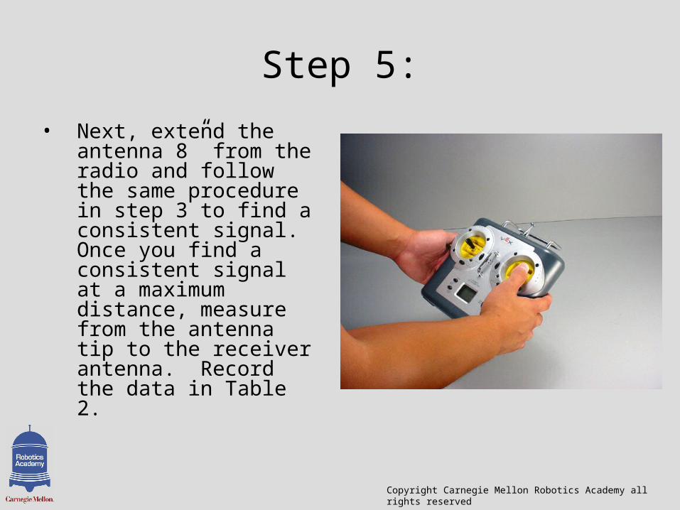
Step 5:
• Next, extend the antenna 8” from the radio and follow the same procedure. Record the data in Table 2.

Copyright Carnegie Mellon Robotics Academy all rights reserved
Step 6:
• Continue to extend the antenna in 4” increments and measuring the distance from antenna tip to the receiver. Record the data in the packet at each increment. You will have 8 distances recorded in Table 2.

Copyright Carnegie Mellon Robotics Academy all rights reserved
Step 7:
• Complete graph comparison Data Sheet, using “Example Data for Student Exercises” as a guide.
• Complete a reflection worksheet.

Copyright Carnegie Mellon Robotics Academy all rights reserved
Transmitter / Receiver Waist High Test
Introduction:
Copyright Carnegie Mellon Robotics Academy all rights reserved
Materials Needed:
• Constructed Robotic System
• Radio Transmitter
• Yard Stick
• Tape Measure
• Range Table 2 Datasheet

Copyright Carnegie Mellon Robotics Academy all rights reserved
Step 1:
• Place the radio in front of Robotic System, waist high (approximately 2’ -3’), and the antenna between 45 degrees and vertical. Extract the antenna to 1” to gain minimal reception.

Copyright Carnegie Mellon Robotics Academy all rights reserved
Step 2:
• Start by pushing down the joystick to start the motor. Slowly back up with the radio at your waist tilted at 45 degrees. Once you find the greatest distance of consistent communication record it in data table 3.

Copyright Carnegie Mellon Robotics Academy all rights reserved
Step 3:
• Using the yard stick, extend the antenna 4” from the radio and follow the same procedure in step 3 to find a consistent signal. Once you find a consistent signal at a maximum distance, measure from the antenna tip to the receiver antenna. Record the data in Table 3.

Copyright Carnegie Mellon Robotics Academy all rights reserved
Step 4:
• Next, extend the antenna 8” from the radio and follow the same procedure in step 3 to find a consistent signal. Once you find a consistent signal at a maximum distance, measure from the antenna tip to the receiver antenna. Record the data in Table 3.
Copyright Carnegie Mellon Robotics Academy all rights reserved
Step 5:
• Next, extend the antenna 8” from the radio and follow the same procedure in step 3 to find a consistent signal. Once you find a consistent signal at a maximum distance, measure from the antenna tip to the receiver antenna. Record the data in Table 2.

Copyright Carnegie Mellon Robotics Academy all rights reserved
Step 6:
• Continue to extend the antenna in 4” increments and measuring the distance from antenna tip to the receiver. Record the data in the packet at each increment. You will have 8 distances recorded in Table 3.
Copyright Carnegie Mellon Robotics Academy all rights reserved
Step 7:
• Complete graph comparison Data Sheet, using “Example Data for Student Exercises” as a guide.
• Complete a reflection worksheet.

Copyright Carnegie Mellon Robotics Academy all rights reserved
Transmitter / Receiver Test With Obstacles
Introduction:

Copyright Carnegie Mellon Robotics Academy all rights reserved
Materials Needed:
• Constructed Robotic System• Radio Transmitter• Tape Measure• Sheet of Paper• Wood• Sheet Metal• Range Table 2 Datasheet

Copyright Carnegie Mellon Robotics Academy all rights reserved
Step 1:
• Place Robotic System at a stationary point. Turn on VEX controller and radio.

Copyright Carnegie Mellon Robotics Academy all rights reserved
Step 2:
• Place the radio in front of Robotic System, waist high (approximately 2’ -3’), and the antenna between 45 degrees and vertical. Make sure antenna is fully extended from the radio.

Copyright Carnegie Mellon Robotics Academy all rights reserved
Step 3:
• Begin the experiment by placing a piece of paper on top of the receiver and the antenna. Make sure the antenna wire is not in the plastic tube and is wrapped around the receiver. Push forward on the joystick of the radio to turn on the motor of the Robotic System. Slowly walk backwards until the motor stops. Find the maximum distance of consistent connection. Measure the distance from the radio to the antenna. Record the data in Table 4.

Copyright Carnegie Mellon Robotics Academy all rights reserved
Step 4:
• Next place a piece of wood over the antenna where the paper was previously. Repeat the experiment and record the results in data table 4.
Copyright Carnegie Mellon Robotics Academy all rights reserved
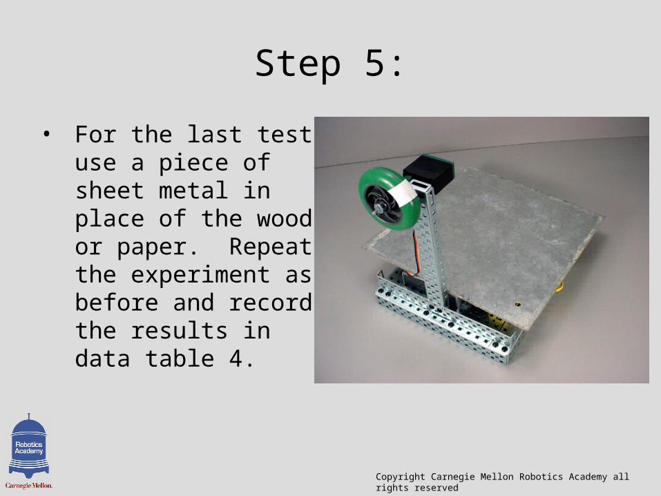
Step 5:
• For the last test use a piece of sheet metal in place of the wood or paper. Repeat the experiment as before and record the results in data table 4.

Copyright Carnegie Mellon Robotics Academy all rights reserved
Step 6:
• Complete graph comparison Data Sheet, using “Example Data for Student Exercises” as a guide.
• Complete a reflection worksheet.