copyright 2002 prentice-hall, inc. chapter 2 object-oriented analysis and design modern systems...
TRANSCRIPT

Copyright 2002 Prentice-Hall, Inc.
Chapter 2Object-Oriented Analysis and Design
Modern Systems Analysis and DesignThird Edition
Jeffrey A. Hoffer Joey F. George
Joseph S. Valacich
Chapter 5System Modeling
Sommerville, "software engineering " , 9th Ed., 2011
20.120.1

Learning Objectives
Key terms Use Case Object Object class State Behavior Operation Encapsulation Constructor Operation Query Operation Update Operation Association Multiplicity
Abstract Class Concrete Class Class-Scope attribute Abstract operation Method Polymorphism Overriding Aggregation Composition Event State transition Sequence diagram
20.220.2

Learning Objectives Discuss the concepts and principles underlying the
object-oriented approach Describe the activities in the different phases of the
object-oriented development life cycle State the advantages of object-oriented modeling
versus traditional systems development approaches Learn to develop requirements models using use-
case diagrams Learn to use class diagrams to develop object
models of the problem domain Learn to develop dynamic models using state,
interaction and activity diagrams Model real-world applications using UML diagrams
20.320.3

IntroductionObject-Oriented systems development life cycle
Process of progressively developing representation of a system component (or object) through the phases of analysis, design and implementation
The model is abstract in the early stages As the model evolves, it becomes more
and more detailed
20.420.4

The Object-Oriented Systems Development Life CycleAnalysis Phase
Model of the real-world application is developed showing its important properties
Model specifies the functional behavior of the system independent of implementation details
Design Phase Analysis model is refined and adapted to the
environment Can be separated into two stages
System design Concerned with overall system architecture
Object design Implementation details are added to system design
20.520.5

The Object-Oriented Systems Development Life Cycle
Implementation Phase Design is implemented using a
programming language or database management system
20.620.6

The Object-Oriented Systems Development Life CycleDeliverables and Outcomes
1. The ability to tackle more challenging problem domains
2. Improved communication among users, analysts, designers and programmers
3. Increased consistency among analysis, design and programming activities
4. Explicit representation of commonality among system components
5. Reusability of analysis, design and programming results
6. Increased consistency among the models developed during object-oriented analysis, design, and programming
20.720.7
System Modeling
System modeling is the process of developing abstract models of a system, with each model presenting a different view or perspective of that system.
System modeling has now come to mean representing a system using some kind of graphical notation, which is now almost always based on notations in the Unified Modeling Language (UML).
System modelling helps the analyst to understand the functionality of the system and models are used to communicate with customers. 8

Existing and planned system models
Models of the existing system are used during requirements engineering. They help clarify what the existing system does and can be used as a basis for discussing its strengths and weaknesses. These then lead to requirements for the new system.
Models of the new system are used during requirements engineering to help explain the proposed requirements to other system stakeholders. Engineers use these models to discuss design proposals and to document the system for implementation.
In a model-driven engineering process, it is possible to generate a complete or partial system implementation from
the system model. 9
The Unified Modeling Language (UML)
A notation that allows the modeler to specify, visualize and construct the artifacts of software systems, as well as business modelsTechniques and notations
Activity diagrams Use cases Sequence diagrams Class diagrams State diagrams
20.1020.10

UML diagram typesActivity diagrams, which show the activities involved in a
process or in data processing .Use case diagrams, which show the interactions
between a system and its environment. Sequence diagrams, which show interactions between
actors and the system and between system components.Class diagrams, which show the object classes in the
system and the associations between these classes.State diagrams, which show how the system reacts to
internal and external events.
11
Process Modeling:Activity Diagrams
Shows the conditional logic for the sequence of system activities needed to accomplish a business process
Clearly shows parallel and alternative behaviors
Can be used to show the logic of a use case
20.1220.12
Use-Case ModelingApplied to analyze functional requirements of the systemPerformed during the analysis phase to help developers understand functional requirements of the system without regard for implementation detailsUse Case
A complete sequence of related actions initiated by an actor
Actor An external entity that interacts with the system
20.1320.13

Figure 20-2Use-case diagram for a university registration system
20.1420.14
Use-Case ModelingDeveloping Use-Case Diagrams Use cases are always initiated by an actor Use cases represent complete functionality of the
system
Relationships Between Use Cases Use cases may participate in relationships with
other use-cases Two types
Extends Adds new behaviors or actions to a use case
Include One use case references another use case
20.1520.15

Sequence diagrams
Sequence diagrams are part of the UML and are used to model the interactions between the actors and the objects within a system.
A sequence diagram shows the sequence of interactions that take place during a particular use case or use case instance.
The objects and actors involved are listed along the top of the diagram, with a dotted line drawn vertically from these.
Interactions between objects are indicated by annotated arrows.
16

Figure 20-24Sequence diagram for a class registration scenario
with prerequisites
20.1720.17
What are Sequence Diagrams?
Sequence Diagrams are interaction diagrams that detail how operations are carried out.
Dynamic interactions between collaborating objects in the system
Represent a scenario in the systemShow a set of collaborating objects, messages
passing between them, and timing.The diagram captures the behavior of a single use
case. It shows objects and the messages that are passed
between these objects for the particular use case.
What do Sequence Diagrams model?
capture the interaction between objects in the context of a collaboration
show object instances that play the roles defined in a collaboration
show the order of the interaction visually by using the vertical axis of the diagram to represent time what messages are sent and when show elements as they interact over time, showing interactions or interaction instances.
do not show the structural relationships between objects
The purpose of Interaction diagrams is to: Model interactions between objects Assist in understanding how a system (a
use case) actually works Verify that a use case description can be
supported by the existing classes Identify responsibilities/operations and
assign them to classes

Participants in a Sequence Diagram
The sequence diagram consists of Active Objects
Messages represented as solid-line arrows (Means by which objects communicate with each other )
Time represented as a vertical progression
Activation The time period during which an object performs an
operation

Analysis Concepts: Dynamic models
Entity Objects Represent the persistent information tracked by the system
(Application domain objects, “Business objects”)
Boundary Objects Represent the interaction between the user and the system
Control Objects: Represent the control tasks performed by the system
<<entity>> Year
<<entity>> Month
<<entity>> Day
<<control>> ChangeDateControl
<<boundary>> LCDDisplayBoundary
<<boundary>> ButtonBoundary

Dynamic ModelingSequence Diagrams
Synchronous Message A type of message in which the caller has
to wait for the receiving object to finish executing the called operation before it can resume execution itself
Simple Message A message that transfers control from the
sender to the recipient without describing the details of the communication
20.2320.23

Sequence Diagram - Objects
A life line illustrates what is happening to an object in a chronological fashion
:Name
Life line
Activation
Object

25
Sequence Diagram – Time & Messages
Messages are used to illustrate communication between different active objects of a sequence diagram.
:Name1 :Name2
Message Two
Actor Message One
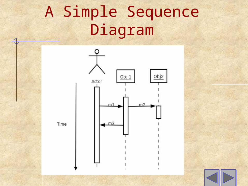
A Simple Sequence Diagram
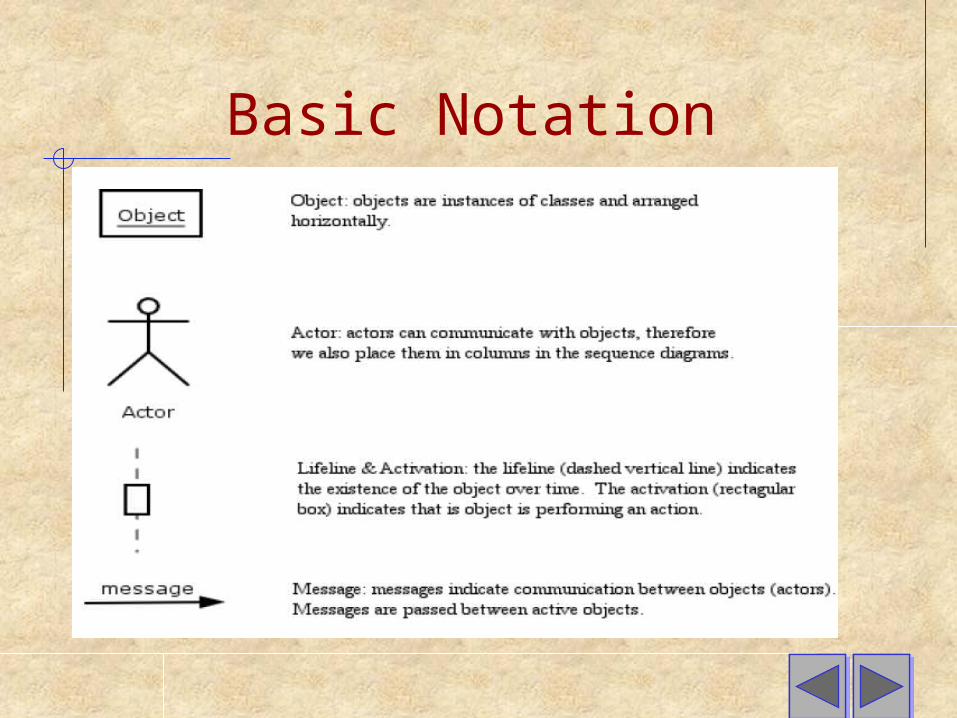
Basic Notation

Example : Online Shopping In order to develop our sequence diagram we will need the use
case text and the specification class diagram:Use Case Text: Buy a Product Online
1. Customer browses through catalog and selects items to buy.2. Customer goes to checkout.3. Customer fills out shipping information.4. System presents full pricing information, including shipping
information.5. Customer fills in credit card information.6. System authorizes purchase.7. System confirms sale immediately.8. System sends confirming email to customer.
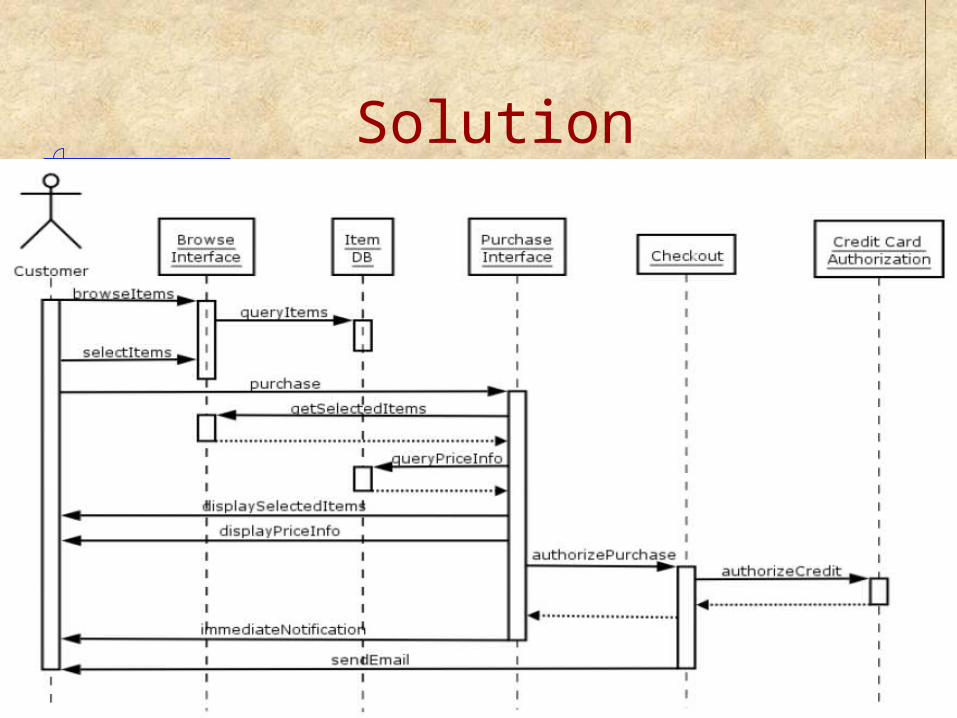
Solution

Questions???
Thanks for your Attention!
Slide 30