copyright 2001, agrawal & bushnellvlsi test: lecture 271 lecture 27 memory and delay-fault...
Post on 21-Dec-2015
218 views
TRANSCRIPT

Copyright 2001, Agrawal & Bushnell
VLSI Test: Lecture 27 1
Lecture 27Memory and Delay-Fault Built-In Self-
Testing
Lecture 27Memory and Delay-Fault Built-In Self-
Testing Definitions Static RAM March Test BIST SRAM BIST with a MISR Neighborhood Pattern Sensitive
Fault (NPSF) DRAM BIST Transparent testing Complex examples Delay fault BIST Summary

Copyright 2001, Agrawal & Bushnell
VLSI Test: Lecture 27 2
DefinitionsDefinitions
Concurrent BIST – Memory test that happens concurrently with normal system operation
Transparent testing – Memory test that is non-concurrent, but preserves the original memory contents from before testing began

Copyright 2001, Agrawal & Bushnell
VLSI Test: Lecture 27 3
LFSR and Inverse Pattern LFSR
LFSR and Inverse Pattern LFSR
NOR gate forces LFSR into all-0 state Get all 2n patterns
Normal LFSR:
G (x) = x3 + x + 1
Inverse LFSR:
G (x) = x3 + x2 + 1

Copyright 2001, Agrawal & Bushnell
VLSI Test: Lecture 27 4
Up / Down LFSRUp / Down LFSR Preferred memory BIST pattern generator
Satisfies March test conditions
X0
D Q MUX
0
1
MUX
0
1
MUX
0
1 D Q D Q
MUX
0
1
X1 X2
Up/Down

Copyright 2001, Agrawal & Bushnell
VLSI Test: Lecture 27 5
Up / Down LFSR Pattern Sequences
Up / Down LFSR Pattern Sequences
Up Counting000100110111011101010001
Down Counting000001010101011111110100

Copyright 2001, Agrawal & Bushnell
VLSI Test: Lecture 27 6
Mutual ComparatorMutual Comparator Test 4 or more memory arrays at same time:
Apply same test commands & addresses to all 4 arrays at same time
Assess errors when one of the di
(responses) disagrees with the others

Copyright 2001, Agrawal & Bushnell
VLSI Test: Lecture 27 7
Mutual Comparator SystemMutual Comparator System
Memory BIST with mutual comparator
Benefit: Need not have good machine response stored or generated

Copyright 2001, Agrawal & Bushnell
VLSI Test: Lecture 27 8
Parallel Memory BISTParallel Memory BIST

Copyright 2001, Agrawal & Bushnell
VLSI Test: Lecture 27 9
Parallel Memory March CParallel Memory March C Add MUX to inputs of write drivers:
Selects normal data input or left neighbor sense amplifier output
Creates shift register during self-test Generalize any March test to test n-bit words
in array rows (x)n means repeat x operations n times
Example: March Cn
{ (w0)n (r0, w0)n; (r0, w1)n (r1, w1)n;
(r1, w0)n (r0, w0)n; (r0, w1)n (r1, w1)n;
(r1, w0)n (r0, w0)n; (r0, w0)n (r0, w0)n}

Copyright 2001, Agrawal & Bushnell
VLSI Test: Lecture 27 10
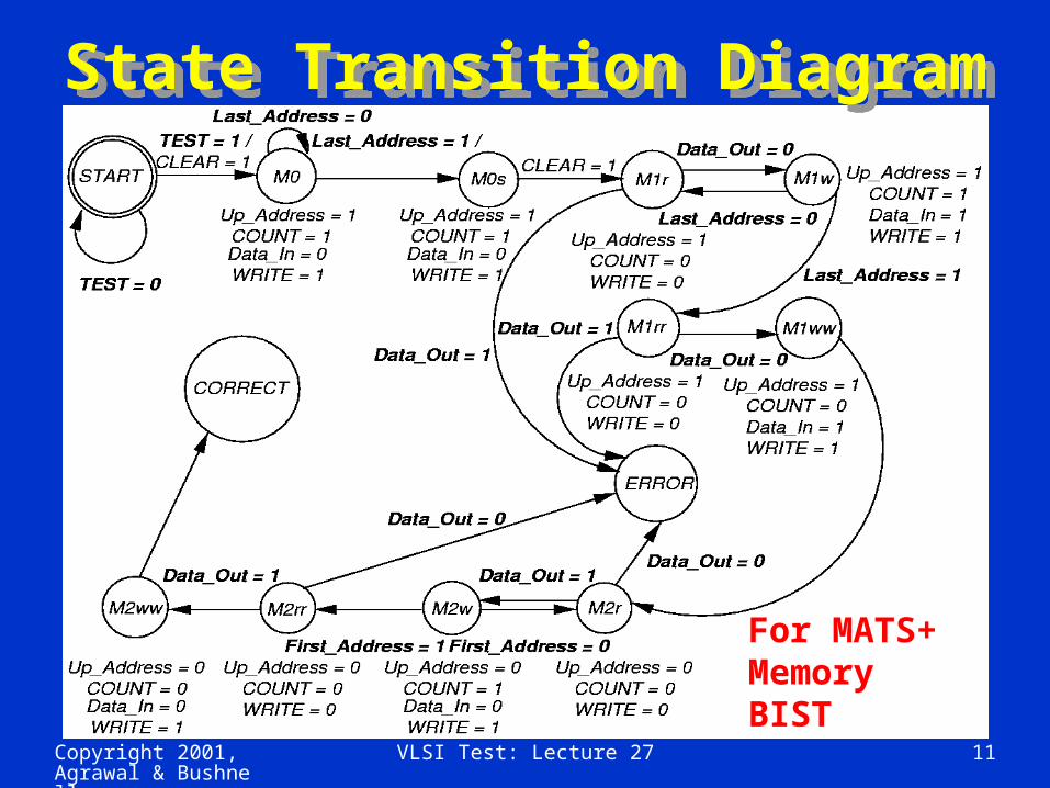
MATS+ RAM BISTMATS+ RAM BIST For single-bit word – can generalize to n-bit
words Need Address MUX – switch row decoder
from normal input to address stepper (which is the Up/Down LFSR)
# states needed:
2 x # March elements + 3 Three extra states:
Start Error Correct Chip area overhead: 1 to 2 % -- widely used
Copyright 2001, Agrawal & Bushnell
VLSI Test: Lecture 27 11
State Transition DiagramState Transition Diagram
For MATS+ Memory BIST

Copyright 2001, Agrawal & Bushnell
VLSI Test: Lecture 27 12
SRAM BIST with MISRSRAM BIST with MISR Use MISR to compress memory outputs Control aliasing by repeating test:
With different MISR feedback polynomial With RAM test patterns in reverse order
March test:
{ (w Address); (r Address); (w Address);
(r Address); (r Address); (w Address);
(r Address); (r Address) } Not proven to detect coupling or address
decoder faults

Copyright 2001, Agrawal & Bushnell
VLSI Test: Lecture 27 13
BIST System with MISRBIST System with MISR

Copyright 2001, Agrawal & Bushnell
VLSI Test: Lecture 27 14
Neighborhood Pattern Sensitive Fault DRAM
BIST
Neighborhood Pattern Sensitive Fault DRAM
BIST Two tests:
MATS+ (to catch address decoder faults) Static NPSF – Type-1 Neighborhood,
2-Group Method, Operation count: 58 n Chip area overhead: 0.09 %, 1 Mb DRAM Static NPSF fault model:
Static Weight-Sensitive Fault (WSF) Changes base cell contents, depending on
number of 1’s in deleted neighborhood

Copyright 2001, Agrawal & Bushnell
VLSI Test: Lecture 27 15
Weight Sensitive FaultsWeight Sensitive Faults
k neighborhood size t-WSF – occurs when deleted neighborhood
pattern has: t cells at “1” k – t –1 cells at “0”
Positive WSF – Base cell can only change 0 1 due to fault
Negative WSF – vice versa Test detecting all positive and negative
static t-WSFs (0 t 4) detects all Static NPSFs
Copyright 2001, Agrawal & Bushnell
VLSI Test: Lecture 27 16
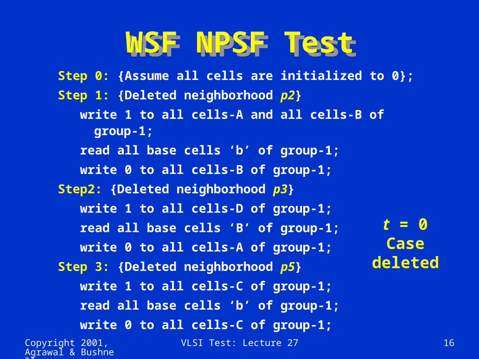
WSF NPSF TestWSF NPSF TestStep 0: {Assume all cells are initialized to 0};
Step 1: {Deleted neighborhood p2}
write 1 to all cells-A and all cells-B of group-1;
read all base cells ‘b’ of group-1;
write 0 to all cells-B of group-1;
Step2: {Deleted neighborhood p3}
write 1 to all cells-D of group-1;
read all base cells ‘B’ of group-1;
write 0 to all cells-A of group-1;
Step 3: {Deleted neighborhood p5}
write 1 to all cells-C of group-1;
read all base cells ‘b’ of group-1;
write 0 to all cells-C of group-1;
t = 0 Case
deleted

Copyright 2001, Agrawal & Bushnell
VLSI Test: Lecture 27 17
WSF NPSF Test (concluded)WSF NPSF Test (concluded)Step 4: {Deleted neighborhood p6}
write 1 to all cells-B of group-1;
read all base cells ‘b’ of group-1;
write 0 to all cells-D of group-1;
Step 5: {Deleted neighborhood p4}
write 1 to all cells-C of group-1;
read all base cells ‘b’ of group-1;
write 0 to all cells-B of group-1;
Step 6: {Deleted neighborhood p1}
write 1 to all cells-A of group-1;
read all base cells ‘b’ of group-1;
write 0 to all cells-A and all cells-C of group-2;
Steps 7-12: Repeat Steps 1-6 for group-2;

Copyright 2001, Agrawal & Bushnell
VLSI Test: Lecture 27 18
WSF Response CompactionWSF Response Compaction Three count functions:
ri -- result of ith read operation
c -- # times a read was done
C1 (R) = ri -- Counts 1’s
C2 (R) = ri ri +1 -- 0 1 transition count
C3 (R) = ri ri +1 -- Counts 0 1 and 1 0
transitions
i = 1
c
c - 1
i = 1
i = 1
c - 1

Copyright 2001, Agrawal & Bushnell
VLSI Test: Lecture 27 19
Count Function ValuesCount Function Values
Entry #
1 (good)2 (bad)3 (bad)4 (bad)
ResponseString0011110010100101
Count FunctionC2 (R)
1012
C1 (R)2222
C3 (R)1133

Copyright 2001, Agrawal & Bushnell
VLSI Test: Lecture 27 20
NPSF BIST Implementation
NPSF BIST Implementation
No memory cell array changes Overheads:
Only address counter size grows with increasing memory size
RAM Size64 kb6 kb
256 kb1 Mb
Chip Area 1.85 %1.21 %0.32 %0.09 %
Control ImplementationROM micro code
Custom logicCustom logicCustom logic

Copyright 2001, Agrawal & Bushnell
VLSI Test: Lecture 27 21
Transparent TestingTransparent Testing Basic rule to preserve memory contents:
Complement stored data in memory an even # of times
To make any memory test transparent: Assume that cell c contains bit v Add initial memory read of v to algorithm Replace any write x of cell c with write
(x v) operation If last write on c returns v, add extra
read and write operations to complement cell contents

Copyright 2001, Agrawal & Bushnell
VLSI Test: Lecture 27 22
Transparent BIST Controller
Transparent BIST Controller
To get signature: Run test without any writes – calculate
signature Rerun test with read and write operations Compare actual signature with 1st pass
signature Must generate both:
Signature predicting response Actual test sequence
MARCH C: Transparent BIST area overhead – 1.2 % Ordinary memory BIST area overhead – 1.0 %

Copyright 2001, Agrawal & Bushnell
VLSI Test: Lecture 27 23
Lucent TechnologiesIntegrated Services Data Network (ISDN) Switch
Lucent TechnologiesIntegrated Services Data Network (ISDN) Switch

Copyright 2001, Agrawal & Bushnell
VLSI Test: Lecture 27 24
Lucent Technologies ISDN Phone Switch Hardware
Lucent Technologies ISDN Phone Switch Hardware
PCM Pulse Code Modulation Uses loop back of intermediate ports in
switch for testing BIST increased system logic gates by 4 % BIST circuit pack area overhead: 1 %
Slight yield decrease Obtained 60% stuck-fault coverage with BIST
Big improvement over fault coverage obtained with external ATE
Diagnostics were easier to write with BIST and ran 8 times faster

Copyright 2001, Agrawal & Bushnell
VLSI Test: Lecture 27 25
Lucent Technologies Example
Lucent Technologies Example Control RAM

Copyright 2001, Agrawal & Bushnell
VLSI Test: Lecture 27 26
Circular BIST UsageCircular BIST Usage

Copyright 2001, Agrawal & Bushnell
VLSI Test: Lecture 27 27
Success of Circular BIST at Lucent
Success of Circular BIST at Lucent
Achieved 98 % fault coverage on tests for these memory faults: SAF Transition NPSF
98 % stuck-at fault coverage for random logic
Advantage: Can test mixture of random logic and memory

Copyright 2001, Agrawal & Bushnell
VLSI Test: Lecture 27 28
Delay-Fault Testing Hazard Problems
Delay-Fault Testing Hazard Problems
Delay distributed along dotted path – wires and logic gates

Copyright 2001, Agrawal & Bushnell
VLSI Test: Lecture 27 29
Delay Fault Test GeneratorsDelay Fault Test Generators Test Invalidation Problem:
Delays in off-path wires (not being tested) confuse the testing process and cause the process to conclude that the path-under-test is good, when in fact it has a severe delay fault
Occurs because the hazard is sampled, rather than the final transition on the path
Single input changing (SIC) pattern generator reduces invalidation -- two known methods: Use Gray Code pattern generator Use Johnson counter (alternate mode is LFSR)

Copyright 2001, Agrawal & Bushnell
VLSI Test: Lecture 27 30
Delay-Fault BIST Pattern GenerationDelay-Fault BIST
Pattern Generation

Copyright 2001, Agrawal & Bushnell
VLSI Test: Lecture 27 31
SummarySummary BIST is gaining acceptance for testability
insertion due to: Reduced chip area overhead (only 1-3 %
chip area for memory BIST) Allows partitioning of testing problem
Memory BIST – widely used, < 1 % overhead Random logic BIST, 13 to 20 % area
overheads Experimental method has only 6.5 %
overhead Used by IBM and Lucent Technologies in
selected products Delay fault BIST – experimental stage