copy
TRANSCRIPT

CLASSIFICATION NOTESNo. 41.3
DET NORSKE VERITASVeritasveien 1, N-1322 Høvik, Norway Tel.: +47 67 57 99 00 Fax: +47 67 57 99 11
CALCULATION OF CRANKSHAFTS FOR DIESEL ENGINES
JANUARY 2002

Comments may be sent by e-mail to [email protected] subscription orders or information about subscription terms, please use [email protected] information about DNV and the Society�s services is found at the Web site http://www.dnv.com
© Det Norske VeritasData processed and typeset by Det Norske Veritas02-01-30 09:34 - Cn41.3.doc
If any person suffers loss or damage which is proved to have been caused by any negligent act or omission of Det Norske Veritas, then Det Norske Veritasshall pay compensation to such person for his proved direct loss or damage. However, the compensation shall not exceed an amount equal to ten times thefee charged for the service in question, provided that the maximum compensation shall never exceed USD 2 million.
In this provision “Det Norske Veritas” shall mean the Foundation Det Norske Veritas as well as all its subsidiaries, directors, officers, employees, agents andany other acting on behalf of Det Norske Veritas.
FOREWORDDET NORSKE VERITAS is an autonomous and independent Foundation with the objective of safeguarding life, property andthe environment at sea and ashore.
DET NORSKE VERITAS AS is a fully owned subsidiary Society of the Foundation. It undertakes classification andcertification of ships, mobile offshore units, fixed offshore structures, facilities and systems for shipping and other industries.The Society also carries out research and development associated with these functions.
DET NORSKE VERITAS operates a worldwide network of survey stations and is authorised by more than 130 nationaladministrations to carry out surveys and, in most cases, issue certificates on their behalf.
Classification Notes
Classification Notes are publications that give practical information on classification of ships and other objects. Examples ofdesign solutions, calculation methods, specifications of test procedures, as well as acceptable repair methods for somecomponents are given as interpretations of the more general rule requirements.
A list of Classification Notes is found in the latest edition of Pt.0 Ch.1 of the �Rules for Classification of Ships�, the �Rules forClassification of Mobile Offshore Units� and the �Rules for Classification of High Speed, Light Craft and Naval SurfaceCraft�.
The list of Classification Notes is also included in the current �Classification Services � Publications� issued by the Society,which is available on request. All publications may be ordered from the Society�s Web site http://exchange.dnv.com.
It is assumed that the execution of the provisions of this Classification Note is entrusted to appropriately qualified andexperienced people, for whose use it has been prepared.
Amendments and Corrections
The main changes are:
− To bring the 1988 version up to date− To include recent work and agreements within CIMAC− To include the results of fatigue testing throughout the past 13 years
DET NORSKE VERITAS
CONTENTS
1. GENERAL................................................................ 41.1 Scope ......................................................................... 41.2 Field of application .................................................... 41.3 Principles of calculation............................................. 51.4 Drawings and particulars to be submitted.................. 62. CALCULATION OF STRESSES .......................... 92.1 Calculation of stresses due to bending moments and
radial forces ............................................................... 92.1.1 Assumptions............................................................... 92.1.2 Calculation of nominal stresses................................ 122.1.3 Calculation of bending stresses in fillets.................. 142.1.4 Calculation of bending stresses in outlet of crankpin
oil bore..................................................................... 152.1.5 Calculation of bending stresses in outlet of journal
oil bore..................................................................... 152.2 Calculation of alternating torsional stresses............. 162.2.1 General..................................................................... 162.2.2 Calculation of nominal alternating torsional
stresses ..................................................................... 162.2.3 Calculation of torsional stresses in fillets and
outlet of oil bores ..................................................... 173. EVALUATION OF STRESS
CONCENTRATION FACTORS.......................... 203.1 General..................................................................... 203.2 Crankpin fillet .......................................................... 223.3 Journal fillet (not applicable to semi-built
crankshaft) ............................................................... 233.4 Outlet of crankpin oil bore....................................... 253.5 Outlet of journal oil bore ......................................... 25
3.6 Inclined oil bores...................................................... 254. ADDITIONAL BENDING STRESSES................ 265. CALCULATION OF EQUIVALENT
ALTERNATING STRESS .................................... 275.1 General ..................................................................... 275.2 Equivalent alternating stress..................................... 276. CALCULATION OF FATIGUE STRENGTH ... 286.1 General ..................................................................... 286.2 Empirical formulae for not surface treated fillets..... 296.2.1 Influence of production methods.............................. 296.2.2 Mechanical strength influence.................................. 306.2.3 Surface roughness influence..................................... 306.2.4 Stress gradient influence. ......................................... 316.2.5 Mean stress influence ............................................... 316.3 Surface treated fillets and/or oil holes ...................... 326.3.1 General ..................................................................... 326.3.2 Empirical formulae for surface treated fillets........... 337. ACCEPTABILITY CRITERIA............................ 367.1 General ..................................................................... 367.2 The Crankpin Fillet Criterion ................................... 367.3 The Journal Fillet Criterion ...................................... 367.4 The Oil Hole Criterion ............................................. 378. CALCULATION OF SHRINK-FITS OF
SEMI-BUILT CRANKSHAFT ............................. 388.1 General ..................................................................... 388.2 Maximum permissible hole in the journal pin.......... 398.3 Necessary minimum oversize of shrink-fit............... 408.4 Maximum permissible oversize of shrink-fit............ 40
4 Classification Notes No. 41.3
January 2002
DET NORSKE VERITAS
1. GENERAL
1.1 ScopeThis Classification Note contains methods for calculation of safety against fatigue failure in pin and journal fillets and in oilbores, as well as safety against slippage for semibuilt crankshafts.
In principle, any relevant calculation method may be applied for this purpose.
E.g. the fatigue criteria assume that maximum resp. minimum bending stresses occur simultaneously with the maximum resp.minimum torsional stresses. (This assumption yields results which are more or less to the safe side.) If properly documented,evaluation of fatigue under multiaxial stress conditions and with rotating principle stress axis may replace the criteria appliedhere.
For simplification purpose, only two methods are presented here, the CIMAC/IACS method and the DNV method.
Common text or criteria are presented on full page width, exclusive CIMAC/IACS text is presented in the left hand column,and exclusive DNV text in the right hand column. The columns are also divided with a drawn midline. Where these twomethods differ, they are presented parallel divided by the midline. When one method has no details, that column is left openand a midline drawn.
A crankshaft will be approved when one of these methods is fulfilled. Crankshafts that cannot satisfy these Rules may besubject to special consideration when detailed calculations and/or measurements are made to demonstrate equivalence to theserules.
1.2 Field of applicationThese Rules apply only to solid-forged and semi-builtcrankshafts of I.C. engines, made of forged or cast steel, withone crankthrow between main bearings, both for propulsionand auxiliary purposes, where the engines are capable ofcontinuous operation at their rated power when running atrated speed.
These methods apply to diesel engines for both mainpropulsion and auxiliary purpose, being designed forcontinuous operation at the specified (nominal) rating. Iffrequent use of overload (in excess of nominal) rating isforeseen, i.e. accumulating several millions of stress cycles,this overload should form the basis for the calculation.Further, the methods apply to solid forged or semibuiltcrankshafts of forged or cast steel, and with one crank throwbetween main bearings. Designs with more than one crankthrow between main bearings, fillets between offset crankpins,fully built crankshafts, or welded crankshafts will be speciallyconsidered on basis of equivalence with the �normal�requirements.
This method is not valid for:
− surface treated fillets,− when fatigue parameter influences are tested,− when working stresses are measured.− Inclined oil bores.
This method is also valid for:
− surface treated fillets,− when fatigue parameter influences are tested,− when working stresses are measured.

Classification Notes No. 41.3 5
January 2002
DET NORSKE VERITAS
1.3 Principles of calculationThe design of crankshafts is based on an evaluation of safety against fatigue in the highly stressed areas.
The calculation is also based on the assumption that the areas exposed to highest stresses are:
− fillet transitions between the crankpin and web as well as between the journal and web,− outlets of crankpin oil bores.
When journal diameter is equal or larger than the crankpinone, the outlets of main journal oil bores are to be formed in asimilar way to the crankpin oil bores, otherwise separatedocumentation of fatigue safety may be required.
− outlets of journal oil bores.
Calculation of crankshaft strength consists initially indetermining the nominal alternating bending and nominalalternating torsional stresses which, multiplied by theappropriate stress concentration factors, result in anequivalent alternating stress (uni-axial stress). Thisequivalent alternating stress is then compared with the fatiguestrength of the selected crankshaft material. This comparisonwill show whether or not the crankshaft concerned isdimensioned adequately.
The methods of crankshaft fatigue are based on:
− A combination of bending and torsional stresses wherebending fatigue strength and torsional fatigue strength areseparately assessed, i.e. also valid for anisotropic materialbehaviour.
− Bending stress measurements, or continuous beamanalysis, or 3-point bending, depending onmanufacturer�s documentation.
− Measured stress concentration factors, or empiricalformulae with one standard deviation above 50%reliability.
− Fatigue strength assessment based on full scale testing orsmall scale, combined with a calculation procedureconsidering the influence of material strength, forgingmethod, mean stress, and when applicable also filletsurface hardening, shot peening or cold rolling includingthe influence of the depth of this surface treatment.
For semibuilt crankshafts, additional criteria cover thesafety against slippage of shrink fits. In case of relativelysmall distance between the pin and the journal shrinkagediameter, the influence of the shrinkage stresses on thefatigue strength is considered.
The sequence for both methods is by determination of:
− nominal stresses ( )− stress concentration factors ( )
− the equivalent stress ( )
− fatigue strengths ( )− acceptance criterion ( )

6 Classification Notes No. 41.3
January 2002
DET NORSKE VERITAS
1.4 Drawings and particulars to be submitted
For the calculation of crankshafts, the documents and particulars listed below are to be submitted:
− crankshaft drawing(which must contain all data in respect of the geometrical configurations of the crankshaft)
− type designation and kind of engine(in-line engine or V-type engine with adjacent connecting-rods, forked connecting-rod or articulated-type connecting-rod)
− operating and combustion method(2-stroke or 4-stroke cycle/direct injection, precombustion chamber, etc.)
− number of cylinders− rated power [kW]− rated engine speed [r/min]− direction or rotation (see Figure 1)− firing order with the respective ignition intervals and, where necessary,
V-angle α v [°] (see Figure 1)
Figure 1 Designation of the cylinders
− cylinder diameter [mm]− stroke [mm]− maximum net cylinder pressure Pmax [bar]− charge air pressure [bar]
(before inlet valves or scavenge ports, whichever applies)− mean indicated pressure [bar]
− all individual reciprocating masses acting on one crank[kg]
− reciprocating mass per cylinder [kg]− rotating mass (ref. to crank radius) per connecting rod− rotating mass (ref. to crank radius) of cranks incl.
counter weights [kg] and positions (lengthwise andangular)

Classification Notes No. 41.3 7
January 2002
DET NORSKE VERITAS
− digitised gas pressure curve presented at equidistant intervals [bar versus Crank Angle] (at least every 5° CA)− connecting-rod length LH [mm]− for engines with articulated-type connecting-rod (see Figure 2)
* distance to link point LA [mm]
* link angle αN [°]
* connecting-rod length LN [mm]
L N
L A
QN
LH
Figure 2 Articulated-type connecting-rod
details of crankshaft material
* material designation (according to ISO,EN,DIN, AISI, etc..)
* mechanical properties of material (minimum values obtained from longitudinal test specimens)
− tensile strength [N/mm²]− yield strength [N/mm²]− reduction in area at break [%]− elongation A5 [%]− impact energy � KV [J]
* type of forging (free form forged, continuous grain flow forged, drop-forged, etc; with description of the forging process)
− finishing method of fillets and oil holes− surface hardening of fillets, if applicable (induction
hardened, nitrided etc.):− extension of surface hardening− hardness at surface (HV)− hardness (HV) as a function of depth [mm]
− cold deformation of fillets, if applicable (shot peening,stroke peening, cold rolling):− extension of treatment− intensity (shot peening)− depth of treatment (residual stresses) for stroke
peening and cold rolling
− Particulars of alternating torsional stress calculations, see item 2.2

8 Classification Notes No. 41.3
January 2002
DET NORSKE VERITAS
Connecting-rodacting component forces
(FR or FT)
Shear force diagrams
(QR)
Bending moment diagrams
(MBR or MBT)
Figure 3 Figure 4
Crankthrow for in line engine Crankthrow for V- enginewith 2 adjacent connecting-rods
L1 = Distance between main journal centre line and crankweb centre (see also Figure 5 for crankshaft without overlap)
L2 = Distance between main journal centre line and connecting-rod centre
L3 = Distance between two adjacent main journal centre lines
Classification Notes No. 41.3 9
January 2002
DET NORSKE VERITAS
2. CALCULATION OF STRESSESExplanations and Basic principles
Chapter 2 deals with nominal stresses that later are multipliedwith stress concentration factors from Chapter 3.
In the case that FE calculations are made of a global modelthat also includes local stresses, the directly determinedstresses are to be used in the acceptance criteria in Chapter 7.
In addition to the alternating stresses, the mean stresses are tobe determined in order to assess the mean stress influence onthe fatigue strength.
The maximum and minimum bending moments and radialforces during a complete working cycle, may be determinedby thorough analysis, e.g. FEM.
Continuous beam model analysis may be applied if itsrelevance can be documented.
If no such analyses are available, the 3-point bending may beused, as described in the following.
2.1 Calculation of stresses due to bending moments and radial forces
2.1.1 AssumptionsThe calculation is based on a statically determined system, composed of a single crankthrow supported in the centre ofadjacent main journals and subject to gas and inertia forces. The bending length is taken as the length between the two mainbearing midpoints (distance L3, see Figure 3 and 4).
The bending moments MBR, MBT are calculated in the relevant section based on triangular bending moment diagrams due to theradial component FR and tangential component FT of the connecting-rod force, respectively (see Figure 3).
For crankthrows with two connecting-rods acting upon one crankpin the relevant bending moments are obtained by superposition of
the two triangular bending moment diagrams according to phase (see Figure 4).
2.1.1.1 Bending moments and radial forces acting in webThe bending moment MBRF and the radial force QRF are taken as acting in the centre of the solid web (distance L1) and arederived from the radial component of the connecting-rod force.
The alternating bending and compressive stresses due to bending moments and radial forces are to be related to the cross-section ofthe crank web. This reference section results from the web thickness W and the web width B (see Figure 5).
Mean stresses are neglected. Mean stresses are also to be determined.

10 Classification Notes No. 41.3
January 2002
DET NORSKE VERITAS
Overlapped crankshaft
Crankshaft without overlap
Figure 5 Reference area of crankweb cross section

Classification Notes No. 41.3 11
January 2002
DET NORSKE VERITAS
2.1.1.2 Bending acting in outlet of crankpin oil bore.The two relevant bending moments are taken in the crankpin cross-section through the oil bore.
MBRO is the bending moment of the radial component of the connecting-rod force
MBTO is the bending moment of the tangential component of theconnecting-rod force
Figure 6 Crankpin section through the oil bore (clockwise rotation)
The alternating stresses due to these bending moments are to be related to the cross-sectional area of the axially boredcrankpin.
Mean bending stresses are neglected. Mean stresses are also to be determined.
Where there are cranks of different geometrical configurations in one crankshaft, the calculation is to cover all crank variants.
The decisive alternating values will then be calculated according to :
[ ]minmaxN XX21X −±=
where :
XN is considered as alternating force, moment or stress
Xmax is maximum value within one working cycle
Xmin is minimum value within one working cycle
A) Mean stresses
The mean values XNM are to be calculated according to:
[ ]minmaxNM XX21X +=
12 Classification Notes No. 41.3
January 2002
DET NORSKE VERITAS
2.1.2 Calculation of nominal stresses
2.1.2.1 Nominal alternating bending and compressive stresses in web cross sectionA) Alternating stresses
The calculation of the nominal alternating bending and compressive stresses
is as follows :
Ke10W
Mσ 3
eqw
BRFNBFN ⋅⋅±=
KeF
Qσ RFNQFN ⋅±=
where :
σBFN [N/mm²] nominal alternating bending stress related to the web
MBRFN [Nm] alternating bending moment related to the center of the web (see Figure 3 and 4)
[ ]minmax BRFBRFBRFN MM
21M −±=
Weqw [mm3] first moment of area (sectional modulus) related to cross-section of web
6WBW
2
eqw⋅=
Ke empirical factor considering to some extent the influence of
adjacent crank and bearing restraint with :
Ke = 0.8 for crosshead engines
Ke = 1.0 for trunk engines
σQFN [N/mm²] nominal alternating compressive stress due to radial force related to the web
QRFN [N] alternating radial force related to the web (see Figure 3 and 4)
[ ]minmax RFRFRFN QQ
21Q −±=
F [mm²] area related to cross-section of web
F = B·W
B) Mean stresses
The mean values are to be calculated according to:
[ ]minmax BRFBRFBRFNM MM
21M +=
Ke10W
Mσ 3
eqw
BRFNMBFNM ⋅⋅=
[ ]minmax RFRFRFNM QQ
21Q +=
KeF
Qσ RFNMQFNM ⋅=

Classification Notes No. 41.3 13
January 2002
DET NORSKE VERITAS
2.1.2.2 Nominal bending stress in outlet of crankpin oil bore A) Alternating stresses
The calculation of nominal alternating bending stress is as follows :
3
e
BONBON 10
WMσ ⋅±=
where :
σBON [N/mm²] nominal alternating bending stress related to the crank pin diameter
MBON [Nm] alternating bending moment calculated at the outlet of crankpin oil bore
[ ]minmax BOBOBON MM
21M −±=
with [ ]Ψ⋅+Ψ⋅= sinMcosMM BROBTOBO
and ψ ° angular position (see Figure 6)
We [mm3] first moment of area (sectional modulus) related to cross-section of axially bored crankpin
����
�
�
����
�
�−
=D
4DD
32πW BH
4
e
B) Mean stresses
The mean values are to be calculated according to:
[ ]minmax BOBOBONM MM
21M +⋅=
3
e
BONMBONM 10
WMσ ⋅=
14 Classification Notes No. 41.3
January 2002
DET NORSKE VERITAS
2.1.2.3 Nominal bending stresses in outlet of journal oil boreA) Alternating stress
If the 3-point bending method is applied (resulting in zerobending moment), the alternating bending moment in thejournal MBONG is to be taken at least as 0,5 � MBON.The nominal alternating bending stress is then:
3
G
4BG
4G
BONGBONG 10
DDD
32π
Mσ ⋅
���
�
���
� −±=
B) Mean stress
If the 3-point bending method is applied, the mean bendingmoment in the journal MBONGM may be neglected.
2.1.3 Calculation of bending stresses in filletsA) Alternating stresses
The calculation of stresses is to be carried out for the crankpin fillet as well as for the journal fillet.
For the crankpin fillet :
( )BFNBBH σασ ⋅±=
where :
BHσ [N/mm2] alternating bending stress in crankpin fillet
Bα [-] stress concentration factor for bending in crankpin fillet (determination - see Chapter 3)
For the journal fillet (not applicable to semi-built crankshaft) :
[ ]QFNQBFNBBG σβσβσ ⋅+⋅±=
where :
BGσ [N/mm2] alternating bending stress in journal fillet
Bβ [-] stress concentration factor for bending in journal fillet (determination - see Chapter 3)
Qβ [-] stress concentration factor for compression due to radial force in journal fillet (determination - see Chapter 3)
Classification Notes No. 41.3 15
January 2002
DET NORSKE VERITAS
B) Mean stresses
The mean stresses are to be calculated according to:
− For the crankpin fillet:BFNMBBHM σασ ⋅=
− For the journal fillet:
QFNMQBFNMBBGM σβσβσ ⋅+⋅−=
Note that the signs above are only correct when the bendingmoment due to max gas pressure is more than twice thebending moment due to mass forces in TDC.
2.1.4 Calculation of bending stresses in outlet of crankpin oil boreA) Alternating stress
( )BONBBO σγσ ⋅±=
where :
BOσ [N/mm2] alternating bending stress in outlet of crankpin oil bore
Bγ [-] stress concentration factor for bending in crankpin oil bore (determination - see Chapter 3)
B) Mean stress
The mean stress is to be calculated according to:
BONMBBOM σγσ ⋅=
2.1.5 Calculation of bending stresses in outlet of journaloil boreA) Alternating stress
( )BONGBGBOG σγσ ⋅±=
where
BONGσ [N/mm2] alternating bending stress in outlet ofjournal oil bore
BGγ [-] stress concentration factor for bending in journal oilbore (determination � see Chapter 3)
B) Mean stress
BONGMBGBOGM σγσ ⋅=
16 Classification Notes No. 41.3
January 2002
DET NORSKE VERITAS
2.2 Calculation of alternating torsional stresses
2.2.1 GeneralThe calculation for nominal alternating torsional stresses is to be undertaken by the engine manufacturer according to theinformation contained in Chapter 2.2.2.
The manufacturer shall specify the maximum nominal alternating torsional stress.
2.2.2 Calculation of nominal alternating torsional stressesThe max. and min. torques are to be ascertained for every mass point of the system and for the entire speed range by means ofa harmonic synthesis of the forced vibrations from the 1st order up to and including the 15th order for 2-stroke cycle enginesand from the 0.5th order up to and including the 12th order for 4-stroke cycle engines. Whilst doing so, allowance must bemade for the damping that exists in the system and for unfavourable conditions (misfiring [*] in one of the cylinders). Thespeed step calculation shall be selected in such a way that any resonance found in the operational speed range of the engineshall be detected.
*) Misfiring is defined as cylinder condition when no combustion occurs but only compression cycle.
Where barred speed ranges are necessary, they shall be arranged so that satisfactory operation is possible despite theirexistence. There are to be no barred speed ranges above a speed ratio of λ ≥ 0.8 for normal firing conditions.
The values received from such calculation are to be submitted.
Alternatively the crankshaft assessment can be based on thespecified maximum alternating torsional stress.
For type approvals it is advised to include a variation of thevarious standard dampers resp. flywheels etc. Directlycoupled engines should take typical installations intoaccount. Flexibly coupled engines may be considered as�cut� in the elastic coupling. Where calculations are notavailable as e.g. for some type approvals, the manufactureris to state a limiting vibratory torque to be used in thecalculation.
The nominal alternating torsional stress in every mass point, which is essential to the assessment, results from the followingequation :
3
P
TNN 10
WMτ ⋅±=
[ ]minmax TTTN MM
21M −±=
��
�
�
��
�
� −=��
�
�
��
�
� −⋅=G
4BG
4G
p
4BH
4
p DDD
16πWor
DDD
16πW

Classification Notes No. 41.3 17
January 2002
DET NORSKE VERITAS
where :
τN [N/mm²] nominal alternating torsional stress referred to crankpin or journal
MTN [Nm] maximum alternating torque
WP [mm3] polar first moment of area (sectional modulus) related to cross-section
of axially bored crankpin or bored journal
MTmax, MTmin extreme values of the torque.
For the purpose of the crankshaft assessment, the nominal alternating torsional stress considered in further calculations is thehighest calculated value, according to above method, occurring at the most torsionally loaded mass point of the crankshaftsystem.
Where barred speed ranges exist, the torsional stresses within these ranges are not to be considered for assessmentcalculations.
The approval of crankshaft will be based on the installation having the largest nominal alternating torsional stress (but notexceeding the maximum figure specified by engine manufacturer).
Thus, for each installation, it is to be ensured by suitable calculation that this approved nominal alternating torsional stress isnot exceeded. This calculation is to be submitted for assessment.
The nominal mean torsional stress is:
3
P
TNMNM 10
WMτ ⋅=
[ ]minmax TTTNM MM
21M +=
This may be determined in every masspoint which isessential to the crankshaft assessment, but a more practicalapproach is to use the mean stress at the crank that has thehighest alternating torque. This can be determined from aquasistatic torque evaluation through the crankshaft(vectorial torque summation assuming clamped end and nodynamics).
2.2.3 Calculation of torsional stresses in fillets and outlet of oil boresThe calculation of stresses is to be carried out for the crankpin fillet, the journal fillet and the outlet of the oil bores.
For the crankpin fillet :
A) Alternating stress
( )ΝΤΗ τατ ⋅±=

18 Classification Notes No. 41.3
January 2002
DET NORSKE VERITAS
where :
Hτ [N/mm2] alternating torsional stress in crankpin fillet
Tα [-] stress concentration factor for torsion in crankpin fillet (determination - see Chapter 3)
Nτ [N/mm2] nominal alternating torsional stress related to crankpin diameter
B) Mean stress
NMTΗΜ τατ ⋅=
where:
NMτ [N/mm2] nominal mean torsional stress related tocrankpin diameter.
For the journal fillet (not applicable to semi-built crankshafts)
A) Alternating stress
( )NTG τβτ ⋅±=
where :
Gτ [N/mm2] alternating torsional stress in journal fillet
Tβ − stress concentration factor for torsion in journal fillet (determination - see Chapter 3)
Nτ [N/mm2] nominal alternating torsional stress related to journal diameter
B) mean stress
NMTGΜ τβτ ⋅=
where:
NMτ [N/mm2] nominal mean torsional stress related tojournal diameter.
Classification Notes No. 41.3 19
January 2002
DET NORSKE VERITAS
For the outlet of crankpin oil bore
A) Alternating stress
( )NTTO τγσ ⋅±=
where :
σTO [N/mm2] alternating stress in outlet of crankpin oil bore due to torsion
γT − stress concentration factor for torsion in outlet of crankpin oil bore (determination- see item 3)
τ N [N/mm2] nominal alternating torsional stress related to crankpin diameter
B) Mean stress
NMTTOM τγσ ⋅=
whereNMτ [N/mm2] nominal mean torsional stress related to
crankpin diameter.
For the outlet of journal oil bore
A) Alternating stress
( )NTGTGO τγσ ⋅±=
where
TGOσ [N/mm2] alternating stress in outlet of journal oilbore due to torsion
TGγ [-] stress concentration factor for torsion in outlet ofjournal oil bore (see item 3)
Nτ [N/mm2] nominal alternating torsional stress related tojournal diameter
B) Mean stress
NMTGTGOM τγσ ⋅=
where
NMτ [N/mm2] nominal mean torsional stress related tojournal diameter.
20 Classification Notes No. 41.3
January 2002
DET NORSKE VERITAS
3. EVALUATION OF STRESS CONCENTRATION FACTORS
3.1 GeneralThe stress concentration factors are evaluated by means of the formulae according to Chapters 3.2, 3.3 and 3.4 applicable tothe fillets and crankpin oil bore of solid forged web-type crankshafts and to the crankpin fillets of semi-built crankshafts only.It must be noticed that stress concentration factor formulae concerning the oil bore are only applicable to a radially drilled oilhole. All formulae are based on investigations of FVV (Forschungsvereinigung Verbrennungskraftmaschinen) for fillets andon investigations of ESDU (Engineering Science Data Unit) for oil holes. All crank dimensions necessary for the calculationof stress concentration factors are shown in Figure 7.
The stress concentration factor for bending (αB, βB) is definedas the ratio of the maximum equivalent stress (VON MISES)� occurring in the fillets under bending load � to the nominalbending stress related to the web cross-section (see AppendixI).
The stress concentration factors in bending(αB, βB) is defined as the ratio between the max. absolutevalue of the PRINCIPAL stresses in the fillets and theabsolute value of the nominal bending stress referred to theweb cross section.
The stress concentration factor for compression (βQ) in thejournal fillet is defined as the ratio of the maximumequivalent stress (VON MISES) � occurring in the fillet dueto the radial force - to the nominal compressive stress relatedto the web cross-section.
The stress concentration factor for compressive stresses (βQ)is defined as the ratio between the maximum fillet stress(absolute value) and the nominal compressive stress(absolute value) referred to the web cross section.
The stress concentration factor for torsion (αT, βT) is defined as the ratio of the maximum equivalent shear stress � occurringin the fillets under torsional load � to the nominal torsional stress related to the axially bored crankpin or journal cross-section(see Appendix I).
The stress concentration factors for bending (γB) and torsion (γT) are defined as the ratio of the maximum principal stress �occurring at the outlet of the crankpin oil-hole under bending and torsional loads � to the corresponding nominal stressrelated to the axially bored crankpin cross section (see Appendix II).
For outlet bores in journals the same definitions apply.
When reliable measurements and/or calculations are available, which can allow direct assessment of stress concentrationfactors, the relevant documents and their analysis method have to be submitted in order to demonstrate their equivalence topresent rules evaluation.
Classification Notes No. 41.3 21
January 2002
DET NORSKE VERITAS
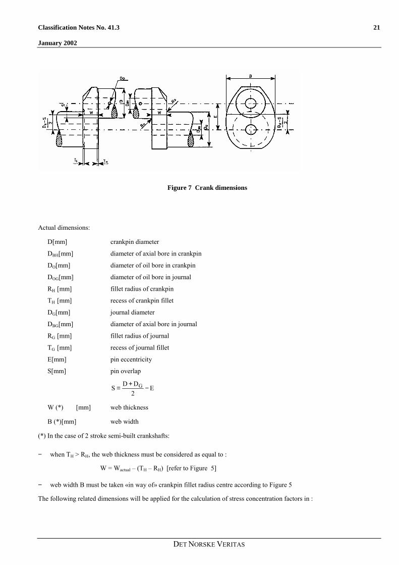
Figure 7 Crank dimensions
Actual dimensions:
D[mm] crankpin diameter
DBH[mm] diameter of axial bore in crankpin
DO[mm] diameter of oil bore in crankpin
DOG[mm] diameter of oil bore in journal
RH [mm] fillet radius of crankpin
TH [mm] recess of crankpin fillet
DG[mm] journal diameter
DBG[mm] diameter of axial bore in journal
RG [mm] fillet radius of journal
TG [mm] recess of journal fillet
E[mm] pin eccentricity
S[mm] pin overlap
E2DDS G −+=
W (*) [mm] web thickness
B (*)[mm] web width
(*) In the case of 2 stroke semi-built crankshafts:
− when TH > RH, the web thickness must be considered as equal to :
W = Wactual � (TH � RH) [refer to Figure 5]
− web width B must be taken «in way of» crankpin fillet radius centre according to Figure 5
The following related dimensions will be applied for the calculation of stress concentration factors in :

22 Classification Notes No. 41.3
January 2002
DET NORSKE VERITAS
Crankpin fillet Journal fillet
D/Rr H= D/Rr G=
s = S/D
w = W/D
b = B/D
dO = DO/D
dG = DBG/D
dH = DBH/D
tH = TH/D
tG = TG/D
Crankpin fillet Journal fillet
D/Rr H= GGG D/Rr =
s = S/D sG = S/DG
w = W/D wG = W/DG
b = B/D bG = B/DG
dO = DO/D dOG = DOG/DG
dH = DBH/D dG = DBG/DG
tH = TH/D tH = TH/D
tG = TG/D tG = TG/D
Stress concentration factors are valid for the ranges of related dimensions for which the investigations have been carried out.Ranges are as follows :
s ≤ 0.5
0.2 ≤ w ≤ 0.8
1.1 ≤ b ≤ 2.2
0.015 ≤ r ≤ 0.13
0 ≤ dG ≤ 0.8
0 ≤ dH ≤ 0.8
0 ≤ dO ≤ 0.2
Low range of s can be extended down to large negative values provided that :
− If calculated f (recess) < 1 then the factor f (recess) is not to be considered (f (recess) = 1)− If s < - 0.5 then f (s,w) and f (r,s) are to be evaluated replacing actual value of s by - 0.5.
The same ranges of validity apply when the relateddimensions are referred to the journal diameter.
As the original (FVV) empirical formulae for the crankpinand the journal fillets were established on the basis of 50percent reliability, and have standard deviations of appr. 10percent (appr. 7 percent of torsion), the coefficients havebeen increased by a factor for bending (presently 1,10) and afactor for torsion (presently 1,07) for the purpose of higherreliability.
3.2 Crankpin filletThe stress concentration factor for bending (αB) is :
αB = KαB · f (s, w) · f (w) · f (b) · f (r ) · f (dG) · f (dH) · f (recess)
KαB = 2.6914
applicable to v.Mises stresses and 50% reliability.
KαB = 3.30
applicable to principal stresses and one standard deviationabove 50% reliability.
Classification Notes No. 41.3 23
January 2002
DET NORSKE VERITAS
where :
f (s,w) = -4.1883 + 29.2004 · w � 77.5925 · w² + 91.9454 · w3 � 40.0416 · w4 + (1-s) · (9.5440 � 58.3480 · w +159.3415 · w² - 192.5846 · w3 + 85.2916 · w4) + (1-s)² · (-3.8399 + 25.0444 · w � 70.5571 · w² + 87.0328· w3 � 39.1832 · w4)
f (w) = 2.1790 · w0.7171
f (b) = 0.6840 � 0.0077 · b + 0.1473 · b2
f ( r) = 0.2081 · r(-0.5231)
f (dG) = 0.9993 + 0.27 · dG � 1.0211 · dG² + 0.5306 · dG3
f (dH) = 0.9978 + 0.3145 · dH � 1.5241 · dH² + 2.4147 · dH3
f (recess) = 1 + (tH + tG) · (1.8 + 3.2 · s)
The stress concentration factor for torsion (αT) is :
αT = KαT · f (r,s) · f (b) · f (w)
KαT = 0,8
applicable to 50% reliability.
KαT = 0,856
applicable to one standard deviation above 50% reliability.
where :
f (r,s) = r (-0.322 + 0.1015 • (1-s))
f (b) = 7.8955 � 10.654 · b + 5.3482 · b² - 0.857 · b3
f (w) = w (-0.145)
3.3 Journal fillet (not applicable to semi-built crankshaft)
The stress concentration factor for bending (βB) is :
βB = 2.7146 · fB (s,w) · fB (w) ·
fB (b) · fB (r) · fB (dG) · fB (dH) · f (recess)
applicable to v.Mises stresses and 50%reliability.
where :
fB (s,w) = � 1.7625 + 2.9821 · w � 1.5276 · w²+ (1 � s) · (5.1169 � 5.8089 · w+ 3.1391 · w²) + (1 � s)² · (-2.1567 + 2.3297 · w� 1.2952 · w²)
fB (w) = 2.2422 · w 0.7548
fB (w) = 0.5616 + 0.1197 · b + 0.1176 · b2
βB = 3.33 · fB (sG,wG) · fB (w) ·
fB (b) · fB (r) · fB (dG) · fB (dH) · f (recess)
applicable to principal stresses and one standard deviationabove 50% reliability.
where :
fB (sG,wG) = �1.7625 + 2.9821 · wG � 1.5276 · wG² + (1 � sG)
· (5.1169 � 5.8089 · wG+ 3.1391 · wG²) + (1 � sG)²· (-2.1567 + 2.3297 · wG� 1.2952 · wG²)
fB (wG) = 2.2422 · wG 0.7548

24 Classification Notes No. 41.3
January 2002
DET NORSKE VERITAS
fB (r) = 0.1908 · r (--0.5568) fB (wG) = 0.5616 + 0.1197 · bG + 0.1176 · bG2
fB (rG) = 0.1908 · rG (--0.5568)
fB (dG) = 1.0012 � 0.6441 · dG + 1.2265 · dG2
fB (dH) = 1.0022 � 0.1903 · dH + 0.0073 · dH2
f (recess) = 1 + (tH + tG) · (1.8 + 3.2 · s)
The stress concentration factor for compression (βQ) due to the radial force is :
βQ = 3.0128 · fQ (s) · fQ (w) · fQ (b) ·
fQ (r) · fQ (dH) · f (recess)
applicable to v.Mises stresses and 50% reliability.
where :
fQ (s) = 0.4368 + 2.1630 · (1-s) � 1.5212 · (1-s)²
fQ (w) =w9369.00637.0
w⋅+
fQ (b) = - 0.5 + b
fQ (r) = 0.5331 · r(-0.2038)
βQ = 3.69 · fQ (s) · fQ (w) · fQ (b) ·
fQ (r) · fQ (dH) · f (recess)
applicable to principal stresses and one standard deviationabove 50% reliability.
where :
fQ (sG) = 0.4368 + 2.1630 · (1-sG) � 1.5212 · (1-sG)²
fQ (wG)=G
Gw9369.00637.0
w⋅+
fQ (bG) = - 0.5 + bG
fQ (rG) = 0.5331 · rG(-0.2038)
fQ (dH) = 0.9937 � 1.1949 · dH + 1.7373 · dH²
f (recess) = 1 + (tH + tG) · (1.8 + 3.2 · s)
The stress concentration factor for torsion (βT) is :
βT = αT
if the diameters and fillet radii of crankpin and journal are thesame.
If crankpin and journal diameters and/or radii are of differentsizes
βT = 0.8 · f (r,s) · f(b) · f(w)
applicable to 50% reliability.
βT = 0.856 · f (rG,sG) · f(bG) · f(wG)
applicable to one standard deviation above 50% reliability.
Classification Notes No. 41.3 25
January 2002
DET NORSKE VERITAS
where :
f (r,s), f (b) and f (w) are to be determined in accordance withitem 3.2. (see calculation of αT), however, the radius of thejournal fillet is to be related to the journal diameter :
G
GDRr =
where :
f (rG,sG) = rG (-0.322 + 0.1015 • (1-s))
f (bG) = 7.8955 � 10.654 · bG + 5.3482 · bG² - 0.857 · bG
3
f (wG) = wG (-0.145)
3.4 Outlet of crankpin oil boreThe stress concentration factor for bending (γB) is :
2OOB d34.6d5.883γ ⋅+⋅−=
The stress concentration factor for torsion (γT) is :
2OOT d30d64γ ⋅+⋅−=
3.5 Outlet of journal oil boreThe stress concentration factor for bending (γBG) is:
2OGOGBG d34.6d5.883γ ⋅+⋅−=
The stress concentration factor for torsion (γTG) is:
2OGOGTG d30d64γ ⋅+⋅−=
3.6 Inclined oil boresInclined oil bores have higher stress concentrations than oilbores perpendicular to the surface.
For small deviations from perpendicular oil bore exit thestress concentration factors in 3.4 and 3.5 are to bemultiplied with:
For bending: /801 ϕ+
For torsion: ψ/200/1001 ++ϕ
Range of validity
φ < 25 degrees
ψ < 40 degrees
where
φ is the angular deviation (degrees) from perpendicular oilbore direction as projected in the transverse (crosswise)plane.
ψ is the angular deviation (degrees) from perpendicular oil bore direction as projected in the longitudinal lengthwise) plane.

26 Classification Notes No. 41.3
January 2002
DET NORSKE VERITAS
4. ADDITIONAL BENDING STRESSESIn addition to the alternating bending stresses in fillets (see item 2.1.3) further bending stresses due to misalignment andbedplate deformation as well as due to axial and bending vibrations are to be considered by applying σadd as given by table:
Type of engine σadd[N/mm2]
Crosshead engines + 30
Trunk piston engines + 10
Other values may be used if substantiated.

Classification Notes No. 41.3 27
January 2002
DET NORSKE VERITAS
5. CALCULATION OF EQUIVALENTALTERNATING STRESS
5.1 GeneralIn the fillets, bending and torsion lead to two different biaxialstress fields which can be represented by a von Misesequivalent stress with the additional assumptions that bendingand torsion stresses are time phased and the correspondingpeak values occur at the same location (see Appendix I).
As a result the equivalent alternating stress is to be calculatedfor the crankpin fillet as well as for the journal fillet by usingthe von Mises criterion.
At the oil hole outlet, bending and torsion lead to twodifferent stress fields which can be represented by anequivalent principal stress equal to the maximum of principalstress resulting from combination of these two stress fieldswith the assumption that bending and torsion are time phased(see Appendix II).
The above two different ways of equivalent stress evaluationboth lead to stresses which may be compared to the samefatigue strength value of crankshaft assessed according to vonMises criterion.
5.2 Equivalent alternating stressThe equivalent alternating stress is calculated in accordancewith the formulae given.
For the crankpin fillet :
( ) 2H
2addBHV τ3σσσ ⋅++±=
For the journal fillet :
( ) 2G
2addBGV τ3σσσ ⋅++±=
For the outlet of crankpin oil bore :
���
�
�
���
�
�
���
�
�++⋅±=
2
BO
TOBOV σ
σ49121σ
31σ
where :
[ ]2V N/mmσ equivalent alternating stress
for other parameters see Chapters 2.1.3., 2.2.3. and 3.4.
28 Classification Notes No. 41.3
January 2002
DET NORSKE VERITAS
6. CALCULATION OF FATIGUE STRENGTHThe fatigue strength is to be understood as that value ofequivalent alternating stress (von Mises) which a crankshaftcan permanently withstand at the most highly stressed points.The fatigue strength may be evaluated by means of thefollowing formulae.
Related to the crankpin diameter :
( )⋅+⋅⋅±= 39.3σ0.42Kσ BDW
��
� +−+⋅+ −4900
σ785D1.0730.264 B0.2
���
�⋅
XB R1
σ196
with :
HX RR = in the fillet area
2/DoRX = in the oil bore area
6.1 GeneralThe fatigue strength is defined as the permanently endurable(i.e. >>107 cycles) alternating principal stress consideringinfluences as mean stress, mechanical strength, size effect,stress gradient, production method, surface roughness, andsurface treatment as hardening and/or cold deformation ifapplicable.
The fatigue strength may be determined by tests or byempirical formulae as given below. Test results may also becombined with pertinent elements of the empirical formulae.E.g. push-pull test results can be combined with mean stressinfluence, and so on.
When the fatigue strength is determined by means of testing(full size or small specimen), the number of test and thestatistical evaluation method must be selected so as to enabledetermination of the fatigue strength as the average valueminus one standard deviation.
Related to the journal diameter :
( )⋅+⋅⋅±= 39.3σ0.42Kσ BDW
��
� +−+⋅+ −4900
σ785D1.0730.264 B0.2G
���
�⋅
GB R1
σ196
where :
[ ]2DW N/mmσ
allowable fatigue strength of crankshaft
K [-]
factor for different types of forged and cast crankshaftswithout surface treatment. Values greater than 1 are onlyapplicable to fatigue strength in fillet area.
= 1.05 for continuous grain flow forged or drop-forgedcrankshafts
= 1.0 for free form forged crankshafts (without continuousgrain flow)
For cast steel crankshafts, the K-factor is to be agreedbetween engine manufacturer and Classification Society.
It is also essential that the tested material is as representativeas possible for the future production. I.e. materialcleanliness, production method, surface roughness, andmechanical strength are not to be superior to the minimumrequirements for the production.
For full size tests of crank throws where a low number ofthrows are tested, the standard deviation must be estimatedconservatively.
107 cycles are to be applied. In order to limit the number oftest crankthrows, it is acceptable to use each crankthrow for107 cycles at low stress levels and increase stepwise afterreaching 107 cycles without failure. In the evaluation of theresults it must be considered that this approach may lead toslightly higher values than the �staircase method�.
Most of the influences as size effect, stress gradient, etc. areautomatically incorporated. However, corrections formechanical strength (of test specimen versus minimumspecified) and mean stress influence have to be considered.
When full size tests are used to determine fatigue strength ofcrankshafts with surface treated fillets (and/or oil holes), theacceptance is to be combined with an approved procedurefor quality control of the surface treatment.
Classification Notes No. 41.3 29
January 2002
DET NORSKE VERITAS
Bσ [N/mm2]
minimum tensile strength of crankshaft material
For other parameters see item 3.3.
When a surface treatment process is applied, it must beapproved by the Society.
These formulae are subject to the following conditions:
Small test specimens taken from a full size crank throw maybe used for crankshafts with not surface treated fillets. Suchspecimens are to be taken parallel to the direction of themaximum fillet stress (absolute value). This applies to bothcrankpin and journal fillets, as well as for oil bores ifapplicable. At least 40 specimens are to be tested in push-pull, and the �staircase method� with 107 cycles is to beused.
6.2 Empirical formulae for not surface treatedfilletsThe fatigue strengths in bending and torsion for web filletsare determined as:
− surfaces of the fillet, the outlet of the oil bore and insidethe oil bore (down to a minimum depth equal to 1.5 timesthe oil bore diameter) shall be smoothly finished.
− for calculation purposes RH, RG or RX are to be taken asnot less than 2 mm.
As an alternative the fatigue strength of the crankshaft can bedetermined by experiment based either on full sizecrankthrow (or crankshaft) or on specimens taken from a fullsize crankthrow.
In any case the experimental procedure for fatigue evaluationof specimens and fatigue strength of crankshaft assessmenthave to be submitted for approval to the Society (method,type of specimens, number of specimens (or crankthrows),number of tests, survival probability, confidence number,.�)
( ) ( ) ( )χfRfσ;σfKσ a0.2Bbf ⋅⋅⋅= )f(σM⋅
( ) ( ) ( )χfRfσ;σf3
1Kτ a0.2Btf ⋅⋅⋅⋅= )f(τM⋅
For oil holes:( ) ( ) ( )χfRfσ;σfKσ a0.2Bhfh ⋅⋅⋅= )f(σM⋅
For Kb, Kt and Kn, see 6.2.1.For ( )0.2B σ;σf , see 6.2.2.
For f(Ra), see 6.2.3.For f(χ), see 6.2.4.For f(σM), see 6.2.5.For f(τM), see 6.2.5.When crankpins and/or journals are surface hardened,special attention must be given to the transition zonesbetween surface hardened areas and the soft core material,see 6.3.1.
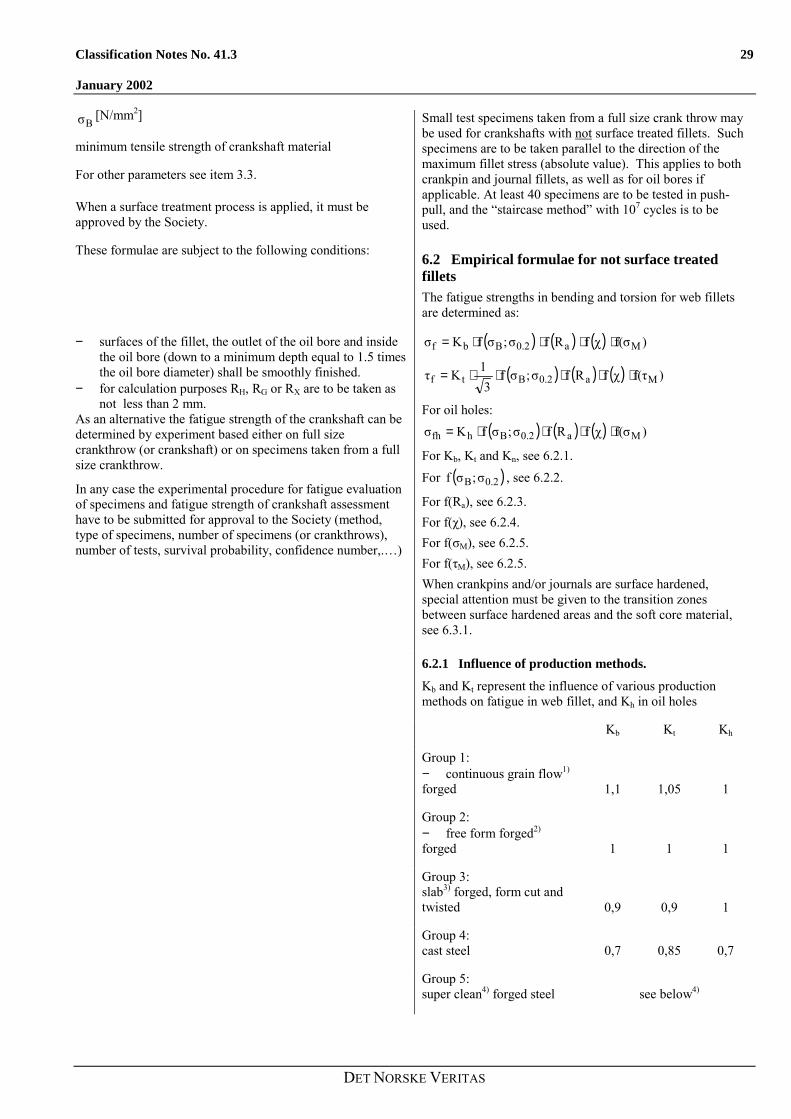
6.2.1 Influence of production methods.
Kb and Kt represent the influence of various productionmethods on fatigue in web fillet, and Kh in oil holes
Kb Kt Kh
Group 1:− continuous grain flow1)
forged 1,1 1,05 1
Group 2:− free form forged2)
forged 1 1 1
Group 3:slab3) forged, form cut andtwisted 0,9 0,9 1
Group 4:cast steel 0,7 0,85 0,7
Group 5:super clean4) forged steel see below4)

30 Classification Notes No. 41.3
January 2002
DET NORSKE VERITAS
1)
Continuous grain flow (cgf) forged means documentedforging that results in a flow of segregations tangential to themain principal stress direction in the web fillets. It does notapply to oil holes (where Kh = 1). The documentation is tobe made on a crankthrow that is cut in the crank plane andetched in order to illustrate the grain flow. It is essential thatthis is made with fillets in finished condition. I.e. forrecessed fillets, cgf may be difficult to obtain as the recessnormally cuts the grain flow.
2)
Free form forging means all kinds of forging processes thatare neither cgf nor slab forging (see footnote 3).
3)
Slab forging means processes where a forged slab is oxycutor machined to form crankthrows, and then twisted intopositions. All similar processes where material from thecentre of the slab ends up in the web fillets fall into thiscategory. This does not apply to oil holes provided that theyare not in a part that origins from the slab centre i.e.normally Kh = 1 for oil holes.
4)
For steels with a especially high cleanliness (see Rules Pt.4,Ch.2, Sec.5) the factors Kb = Kt = Kh = 1,1 for web filletsand oil holes and apply for both cgf and free form forging.When superclean steels are combined with slab forging,Kb = Kt = 1,0 for web fillets and Kh = 1,1 for oil holes.
6.2.2 Mechanical strength influence.f(σB;σ0.2) represents the influence of the mechanical strengthon the push-pull fatigue strength.
f(σB;σ0.2) is the smaller value of
40σ0.33 B +⋅
or 67σ0.38 0.2 +⋅
It should be noted that use of σB>800 MPa or σ0.2 > 600 MPamay require stricter requirements to cleanliness than thosegiven in some material specifications.
6.2.3 Surface roughness influence.f(Ra) represents the influences of surfaces roughness.
The surface roughness condition of all web fillets and oilholes (to a depth of at least 1,5 times the oil bore diameter)is assumed to be smooth grinding or better, preferablypolishing. Web fillets should be polished along the filletcontour. Hence the f(Ra) is unity. However, for oil boresthat are not smoothly finished to the above mentioned depth,a factor of f(Ra) = 0,9 applies.

Classification Notes No. 41.3 31
January 2002
DET NORSKE VERITAS
6.2.4 Stress gradient influence.f(χ) represents the size influence due to the stress gradient.
The other size influences such as statistical andmetallurgical are not included because:
− The statistical is covered by the use of one standarddeviation below average for test results, respectivelycovered by the empirical formulae for push-pull.
− The metallurgical is covered by use of representativetest specimens taken from one (or both) extended end(s)of the forged crankshafts or equivalent for singlethrows.
f(χ) is different for bending and torsion and may be taken as:
x
712σ
R2100,51f(χ(
0.2 ��
���
�−⋅+= for bending
x
712σ
R1100,51f(χ(
0.2 ��
���
�−⋅+= for torsion
where RX is RH for crankpin fillets and RG for journal fillets
and 2
D.resp2
D OGO
for oil bores. However, Rx is not to be taken <2mm forcalculation purposes.
6.2.5 Mean stress influenceThe mean stress influence is considered by means of aparabolic relation as:
B
meanσσ1− resp.
B
meanττ
1−
where 3/στ BB =
For crankpin fillets: σMean = σBHM , see 2.1.3B
τMean = τHM , see 2.2.3 B
For journal fillets: σMean = σBGM , see 2.1.3B
τMean = τGM , see 2.2.3 B
It should be noted that crankpin fillet mean bending stressesnormally are positive (tension) and hence reduce the fatiguestrength. Journal fillet mean bending stresses are normallynegative (compression) and hence increase the fatiguestrength. For torsion, any mean stress regardless directionreduces the fatigue strength.

32 Classification Notes No. 41.3
January 2002
DET NORSKE VERITAS
For oil holes in crankpin:
���
�
�
���
�
�
���
�
�++⋅=
2
BOM
TOMBOMMean σ
σ49121σ
31σ
For σBOM , see 2.1.4 B
For σTOM , see 2.2.3 B.
For oil holes in journals:
���
�
�
���
�
�
���
�
�++⋅=
2
BOGM
TOGMBOGMMean σ
σ49121σ
31σ
For σBOGM , see 2.1.5 B
For σTOGM , see 2.2.3 B.
6.3 Surface treated fillets and/or oil holes
6.3.1 GeneralSurface treatment of fillets and oil holes means any methodaiming at increased fatigue strength in local areas. It isdivided into surface hardening and cold deformation.
Surface hardening means all kinds of thermic treatment suchas induction hardening and nitriding. These processes resultin increased surface hardness, and if properly made, alsocompressive residual stresses to a certain depth. However,especially for induction hardening, the transition zonesdepthwise and at the end of the layer have tensile residualstresses. It is therefore essential to check also transitionzones for fatigue.
Cold deformation means all kinds of �cold� treatments suchas shot peening, stroke peening, cold rolling and ball coining(oil holes). These processes result in negligible hardnessincrease but in considerable compressive residual stresses toa certain depth. Also with these processes the transitionzones have to be checked for fatigue.
When full size testing is used to determine the fatiguestrength, it is normally restricted to bending fatigue in webfillets and with purely reversed stresses.
The mean stress influence can be calculated as given in 6.2.5but replacing σB with 3.3 · HV where HV is the fillet surfacehardness. The determined web reversed bending fatiguestrength may be converted to web torsion fatigue strength bydividing with 3 provided sufficient depth of the treatment.Due to the smaller stress gradient in torsion, a deepertreatment may be necessary. This may be checked by theempirical formulae in (6.3.2).
Classification Notes No. 41.3 33
January 2002
DET NORSKE VERITAS
When crankpins and/or journals are surface hardened, the oilholes are to be specially considered. The highest stressesoccur in the transition between the edge rounding and thehole. From this point on there is a linear decrease to zero atpin centre. For induction hardening there will be a hard/softtransition near the pin surface. In this transition zone therewill be tensile residual stresses which reduce the fatiguestrength of the base material. The reduction can be assignificant as 10-20%. Note that this reduction isindependent of the surface roughness influence of f(Ra).
a)
When the hard/soft transition zone is outside of the higheststressed point, i.e. in the outer part of the edge rounding, theoil hole criteria may be applied with use of the unmodifiedfatigue strength of the base material.
b)
When the hard/soft transition zone is close to (consider thetolerances on hardened depth) the highest stressed point, i.e.near the transition between the edge rounding and the hole,the oil hole criteria are to be applied with a fatigue strengthof the base material that is reduced with 15%.
c)When the hard/soft transition zone is well inside the higheststressed point, the decisive point for fatigue initiation is nolonger the highest stressed point. The critical point will bethe hard/soft transition. Even though there is a linear stressdecrease inward, the induction hardened layer will always beso small relative to the pin radius that a detailed fatigueconsideration is hardly worthwhile, and the recommendationin b) applies.
6.3.2 Empirical formulae for surface treated filletsBoth surface and subsurface initiated fatigue are to beconsidered. This method may also be used in combinationwith full size fatigue tests where e.g. only reversed bendingfatigue is investigated, see also 6.3.1.
When not combined with fatigue test results, the followingapplies:
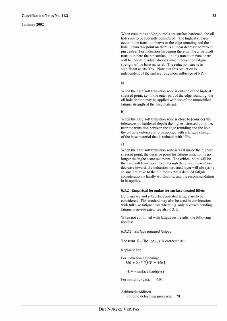
6.3.2.1 Surface initiated fatigue
The term )σ;f(σK 0.2Bb ⋅ is corrected as:
Replaced by:
For induction hardening: ( )45045,0380 −⋅+ HV
(HV = surface hardness)
For nitriding (gas): 450
Arithmetic additionFor cold deforming processes: 70

34 Classification Notes No. 41.3
January 2002
DET NORSKE VERITAS
The corresponding values for torsion are found by divisionwith 3 .The corrected values for ( )0.2Bb σ;σfK ⋅ and
( )0.2Bt σ;σfK ⋅ are to be further processed as given in 6.2after possible correction in 6.3.2.2.
For surface hardening the mean stress influence is assessedby replacing Bσ with ⋅3.3 HV, and the stress gradientinfluence ( )χf is to be calculated with a fictive 265σ0.2 = .
6.3.2.2 Subsurface initiated fatigue
Subsurface initiated fatigue depends on the stress gradients,hardness versus depth profiles, residual stresses versus depthand the defect size tolerances.
In order to have full advantage of the surface fatiguestrength, the necessary (in order to avoid subsurfaceinitiation prior to surface initiation) depths of the hardenedlayer are:
For bending:
��
�
�
��
�
�
���
�
�
σσ
−+σσ
−⋅+⋅
⋅≥2
fsur
fsub
fsur
fsubb 121
W)(R2WRt
For torsion:
��
�
�
��
�
�
���
�
�−+−⋅
+⋅≥
2
fsur
fsub
fsur
fsubt τ
τ12ττ1
D2RDRt
(The terms W)(R2
WR+⋅
⋅ respectively DR2
DR+⋅
⋅
represent the influence of the stress gradient. The bracketsrepresent the dimensionless shape of the subsurface workingstresses)
where:
tb, tt = the depth of the surface treatment.
This means for
− induction hardening the depth to a hardness of corehardness plus 30 HV.
− nitriding the depth to 400 HV.− cold deformation processes the depth to a compressive
residual stress of 10% of the core yield strength.
R = applicable fillet radius, i.e. RH or RG (for multiradii fillets, use the largest radius where high stresses occur)
D = applicable diameter, i.e. D or DG
W = web thickness
Classification Notes No. 41.3 35
January 2002
DET NORSKE VERITAS
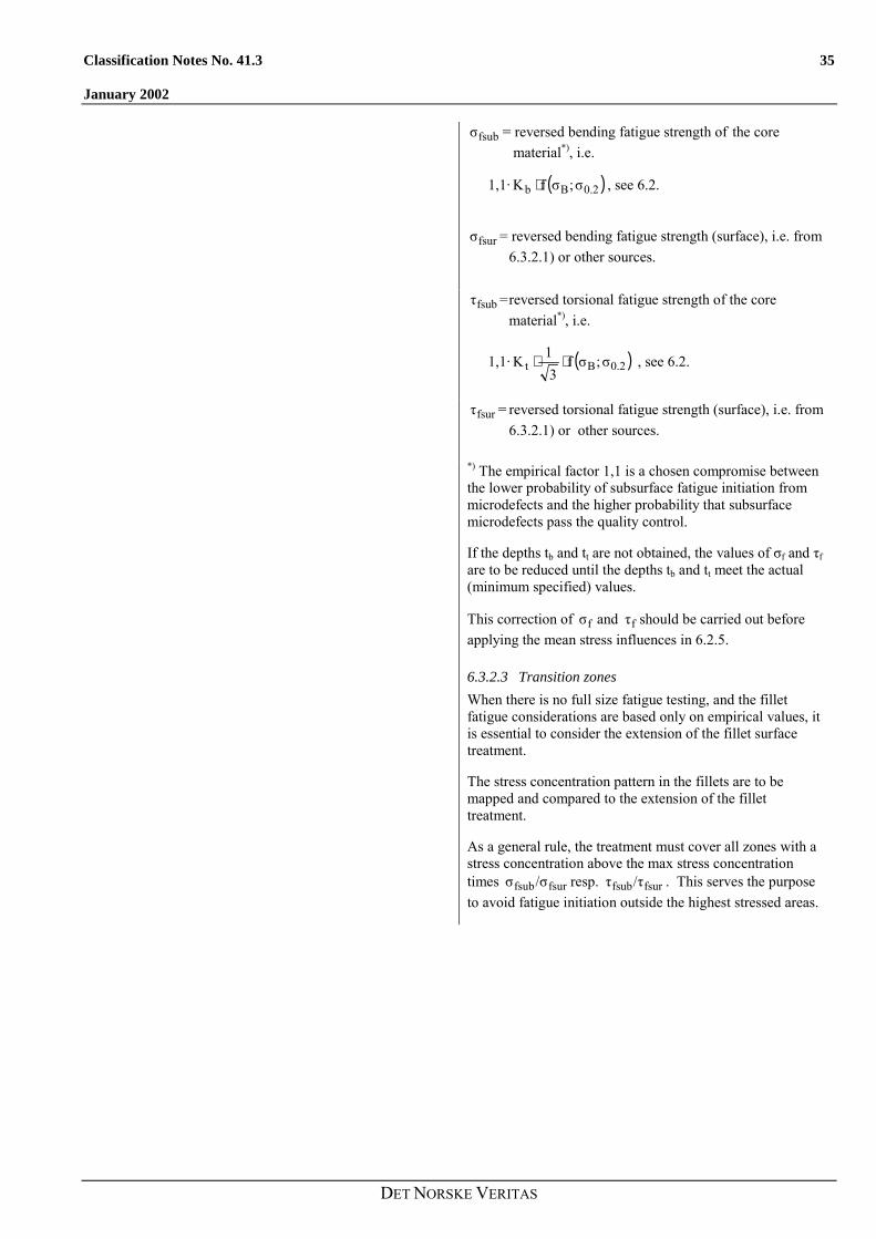
fsubσ = reversed bending fatigue strength of the corematerial*), i.e.
1,1· ( )0.2Bb σ;σfK ⋅ , see 6.2.
fsurσ = reversed bending fatigue strength (surface), i.e. from6.3.2.1) or other sources.
fsubτ =reversed torsional fatigue strength of the corematerial*), i.e.
1,1· ( )0.2Bt σ;σf3
1K ⋅⋅ , see 6.2.
fsurτ = reversed torsional fatigue strength (surface), i.e. from6.3.2.1) or other sources.
*) The empirical factor 1,1 is a chosen compromise betweenthe lower probability of subsurface fatigue initiation frommicrodefects and the higher probability that subsurfacemicrodefects pass the quality control.
If the depths tb and tt are not obtained, the values of σf and τfare to be reduced until the depths tb and tt meet the actual(minimum specified) values.
This correction of fσ and fτ should be carried out beforeapplying the mean stress influences in 6.2.5.
6.3.2.3 Transition zonesWhen there is no full size fatigue testing, and the filletfatigue considerations are based only on empirical values, itis essential to consider the extension of the fillet surfacetreatment.
The stress concentration pattern in the fillets are to bemapped and compared to the extension of the fillettreatment.
As a general rule, the treatment must cover all zones with astress concentration above the max stress concentrationtimes fsurfsub/σσ resp. fsurfsub/ττ . This serves the purposeto avoid fatigue initiation outside the highest stressed areas.

36 Classification Notes No. 41.3
January 2002
DET NORSKE VERITAS
7. ACCEPTABILITY CRITERIAThe sufficient dimensioning of a crankshaft is confirmed by acomparison of the equivalent alternating stress and the fatiguestrength. This comparison has to be carried out for thecrankpin fillet, the journal fillet, the outlet of crankpin oilbore and is based on the formula :
V
DWσσQ =
where :
[ ]−Q acceptability factor
Adequate dimensioning of the crankshaft is ensured if thesmallest of all acceptability factors satisfies the criteria :
15.1Q ≥
7.1 GeneralFor the fatigue criteria mentioned in 7.2, 7.3 and 7.4 acommon minimum safety factor applies, as:
S = 1,15
All stresses are in N/mm2.
7.2 The Crankpin Fillet CriterionThe stresses in the crankpin fillet are to fulfil the followingcriterion:
2
2
fH
H2
fH
HS1
ττ
σσ ≤��
�
�
�+��
�
�
�
where
Hσ = addBH σσ + , see 2.1.3 resp. 4.
Hτ = see 2.2.3.
fHσ = fσ as determined in 6 for thecrankpin fillet
fHτ = fτ as determined in 6 for thecrankpin fillet
For semibuilt crankshafts with a relatively low distancebetween the pin and the shrunk in journal(s = S / D > -0,1), it is necessary to consider the influence ofthe shrinkage stresses on the crankpin fillet fatigue strength.This applies in particular to the approx. 45 degrees crankpinplane.
The above mentioned criterion may be used, however, withsome modifications as:
− Nominal bending stresses as well as stress concentrationfactors to be calculated in the 45 degree plane.
− Shrinkage stresses in the fillet of the 45û plane to beadded to the mean bending stresses when determining thefatigue strength.
7.3 The Journal Fillet Criterion(Not applicable to semibuilt crankshafts.)
The stresses in the journal fillet are to fulfil the followingcriterion:
2
2
fG
G2
fG
G
S1
ττ
σσ
≤���
����
�+�
��
����
�
Classification Notes No. 41.3 37
January 2002
DET NORSKE VERITAS
where
Gσ = addBG σσ + , see 2.1.3 resp. 4.
Gτ = see 2.2.3.
fGσ = fσ as determined in 6 for thejournal fillet
fGτ = fτ as determined in 6 for thejournal fillet
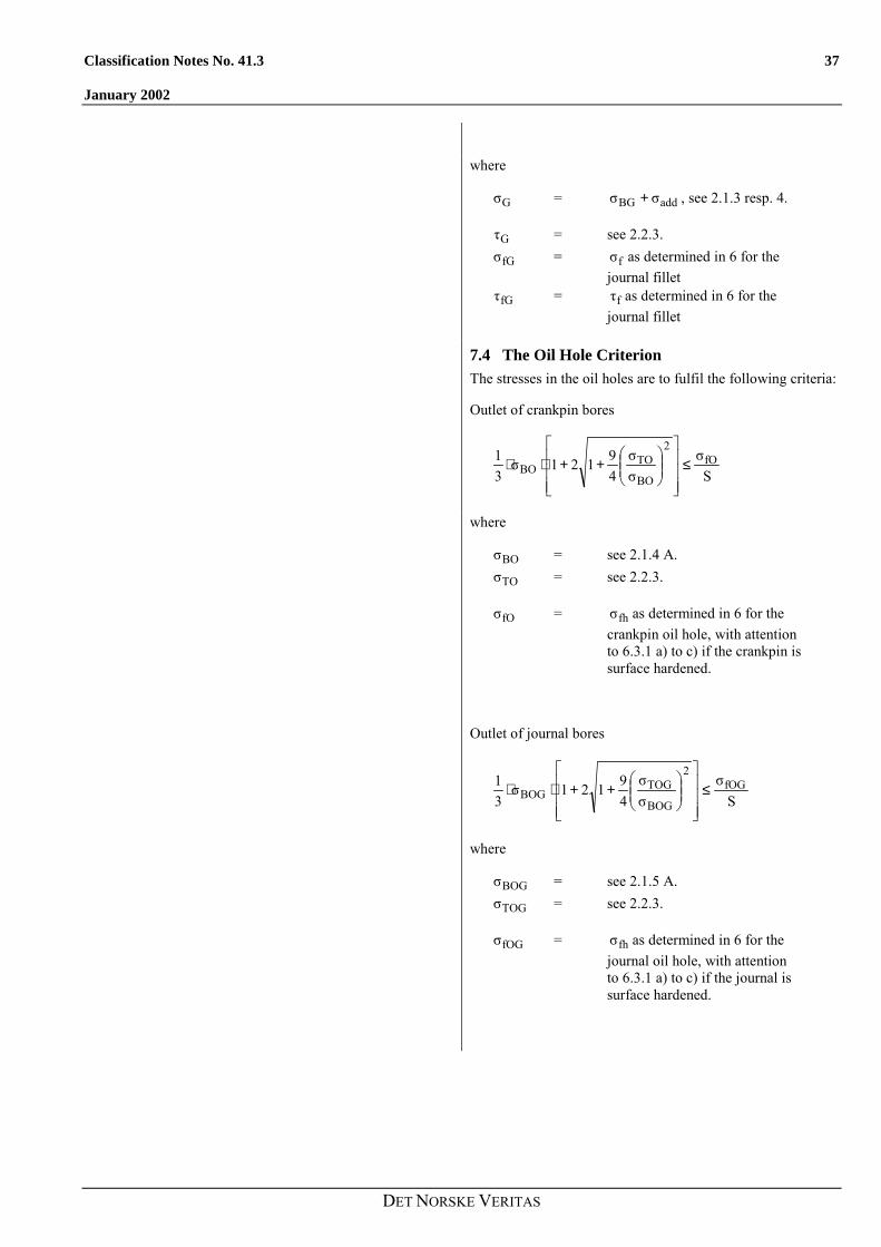
7.4 The Oil Hole CriterionThe stresses in the oil holes are to fulfil the following criteria:
Outlet of crankpin bores
Sσ
σσ
49121σ
31 fO
2
BO
TOBO ≤
���
�
�
���
�
�
���
�
�++⋅⋅
where
BOσ = see 2.1.4 A.
TOσ = see 2.2.3.
fOσ = fhσ as determined in 6 for thecrankpin oil hole, with attentionto 6.3.1 a) to c) if the crankpin issurface hardened.
Outlet of journal bores
Sσ
σσ
49121σ
31 fOG
2
BOG
TOGBOG ≤
���
�
�
���
�
�
���
�
�++⋅⋅
where
BOGσ = see 2.1.5 A.
TOGσ = see 2.2.3.
fOGσ = fhσ as determined in 6 for thejournal oil hole, with attentionto 6.3.1 a) to c) if the journal issurface hardened.

38 Classification Notes No. 41.3
January 2002
DET NORSKE VERITAS
8. CALCULATION OF SHRINK-FITS OF SEMI-BUILT CRANKSHAFT
8.1 GeneralThe criteria given in 8.2 to 8.4 serve the purpose of both safetorque transmission and to prevent detrimental fretting underthe edge of the shrinkage.
All crank dimensions necessary for the calculation of the shrink-fit are shown in Figure 8.
Figure 8 Crankthrow of semi-built crankshaftWhere :
DA [mm] outside diameter of web or twice the minimum distance x between centre-line of journals and outer contour ofweb, whichever is less
DS [mm] shrink diameter
DG [mm] journal diameter
DBG [mm] diameter of axial bore in journal
LS [mm] length of shrink-fit
RG [mm] fillet radius of journal
y [mm] distance between the adjacent generating lines of journal and pin y ≥ 0.05 · DS
Where y is less than 0.1 · DS special consideration is to be given to the effect of the stress due to the shrink-fiton the fatigue strength at the crankpin fillet.

Classification Notes No. 41.3 39
January 2002
DET NORSKE VERITAS
Respecting the radius of the transition from the journal to the shrink diameter, the following should be complied with :
RG ≥ 0.015 · DG
and
RG ≥ 0.5 · (DS � DG)
where the greater value is to be considered.
The actual oversize Z of the shrink-fit must be within the limits Zmin and Zmax calculated in accordance with items 8.3 and 8.4.
In the case where 8.2 condition cannot be fulfilled then 8.3 and 8.4 calculation methods of Zmin and Zmax are not applicable dueto multizone-plasticity problems.
In such case Zmin and Zmax have to be established based on FEM calculations.
8.2 Maximum permissible hole in the journal pin
The maximum permissible hole diameter in the journal pin is calculated in accordance with the following formula :
SPS2S
maxRSBG
σLDπµMS40001DD
⋅⋅⋅⋅⋅⋅−⋅=
where :
SR [-] safety factor against slipping, however a value not less than2 is to be taken unless documented by experiments.
Mmax [Nm] absolute maximum value of the torque MTmax in accordancewith 2.2.2
µ [-] coefficient for static friction, however a value not greater than0.2 is to be taken unless documented by experiments.
σSP [N/mm2] minimum yield strength of material for journal pin
This condition serves to avoid plasticity in the hole of the journal pin.

40 Classification Notes No. 41.3
January 2002
DET NORSKE VERITAS
8.3 Necessary minimum oversize of shrink-fitThe necessary minimum oversize is determined by the greater value calculated according to :
m
sswmin E
DσZ ⋅≥
and
( ) ( )2S
2A
2S
2A
ssm
maxRmin
Q1Q1QQ1
LDEMS
πµ4000Z
−⋅−⋅−⋅
⋅⋅⋅⋅
⋅≥
where :
Zmin[mm] minimum oversize
Em [N/mm²] Young�s modulus
σSW[N/mm²] minimum yield strength of material for crank web
QA [-] web ratio, A
SA D
DQ =
QS [-] shaft ratio, S
BGS D
DQ =
8.4 Maximum permissible oversize of shrink-fitThe maximum permissible oversize is calculated according to :
���
�
�+⋅≤
10000.8
EσDZ
m
swsmax
This condition serves to restrict the shrinkage induced meanstress in the fillet.
Higher values may be accepted for forged steel, but limited tothe shrinkage amount that results in a plastified zone of 30%of the minimum web thickness in radial direction.