copy of layout 1 - bridco
TRANSCRIPT

It is recommended for the eye to be formed around the thimble.
Swage ferrules (crimps) on stainless steel wire should always be copper.Aluminium ferrules are not suitable and should only be used on galvanised wire.
Swaging, (crimping) can done by either a special hand tool or hydraulic press.
There are many different combinatons and uses for BRIDCO stainless steel fittings and wire ropeterminations.
The information shown in the centre spread of the catalogue is intended as a guide to help select the combination orsystem most suited to your application.
For further details including dimensions and maximun loads on these and many other BRIDCO stainless steel products, refer to appropriate page in our catalogue or consult your local BRIDCO stockist.
WWhhaatt GGrraaddee ooff SSttaaiinnlleessss SStteeeell??
The two most common grades are #304 and #316
#304 is commonly used and has a good level of corrosion resistance but can stain if exposed to a heavy salt atmosphere. Periodic wash downs with fresh water helps combat staining which can be readily cleaned with a mildhydrochloric or nitric acid wash.
#316 offers the highest resistance to corrosion and is often regarded as the premium grade. It is recommended to use#316 if materials are exposed to a heavy salt environment.
SSwwaaggee EEyyeess
TTHHEE MMOOSSTT CCOOMMMMOONN SSTTYYLLEESS OOFF SSTTAAIINNLLEESSSS SSTTEEEELL RROOPPEE ::
WWhhiicchh WWiirree RRooppee TTeerrmmiinnaattiioonn ??
A stiff wire rope made up of 19 single strands. Commonly used for standing rigging, mast stays, etc.
Has a smooth finish and looks good with swage terminals.
Semi flexible. Easy to hand crimp and capable of limited angles. Commonly used on balustrading and safety rails.
Very Flexible. Easiest to hand crimp.
Used for running rigging or where sharp turns are required.
11 XX 1199
77 XX 77
77 XX 1199
telephone (07) 55 935 688 fax (07) 55 935 872
45
FERRULES

FERRULES
www.bridco.com.au [email protected]
HHaanndd SSwwaaggeess
The CP range of copper and aluminium sleeves (ferrules) are specifically designed for use with handcrimping tools. The results, when used with the correct tools, properly adjusted, are extremely strongwith an even structure of metal surrounding the wire. Copper sleeves are recommended for use onstainless steel wire ropes. For galvanised wire ropes, aluminium sleeves can be used.
Please note that although hand crimping can give excellent results it should not be used on wire usedfor lifting purposes. Use approved methods only.
Use normal hand swage tool for crimping stoppers, use the hole one size below the wire size ie:,3mm wire rope use 2mm hole on the tool.PRESSING PROCEDURE – STOP FERRULES
1. Feed the wire through the ferrule to leave at least one wire diameter in length protruding from the ferrule.
2. Beginning at the tail end of the ferrule press along the length of the ferrule using the full width of the plier jaw.
3. Rotate the ferrule 90 degrees and repeat, pressing surplus metal back into the ferrule.
4. Rotate back 90 degrees and repeat the process.
STOPPERS
CODE SUITWIRE
BEFORESWAGE
DIA
AFTERSWAGE
DIA
STARTSSLIPPING
CP-115S 1.5mm 5.1 3.5 195
CP-130S 3.2mm 6.35 5 340
CP-140S 4.0mm 10.5 6.8 544
CP-150S 5.0mm 10.9 7.5 725
46

FERRULES
COPPER SLEAVE (NP = NICKEL PLATED)
**11 BBOORREE == DDiiaa ooff ccaavviittyy iinn tthhee pprreessssiinngg ttooooll oorr ddiiee uusseedd ffoorr pprreessssiinngg..
**22 == WWhheenn uussiinngg CCPP HHaanndd TToooollss..
COPPER SLEEVES FOR FIBRE ROPE
CODE USETOOL
FORROPE BORE
LTHBEFORE
SWAGING
BITESPER
SLEEVECP-140R CP-763 4mm 6.9 6 1
CP-160R CP-775 6mm 9.1 8 1
CP-180R CP-775 8mm 10.9 8 1
CP-110R CP-778 10mm 12.8 10 2
telephone (07) 55 935 688 fax (07) 55 935 872
CODE FOR WIRE SIZEMM IMP BORE *1 LENGTH BEFORE
SWAGINGBITES PER SLEEVE
(MIN) *2CP-105 1.5 1/16” 4.9 8 2CP-115NP 1.6 1/16” 4.9 8.8 2CP-115S 1.5 1/16” 4.9 8.8 2CP-120 2 5/64” 4.9 9 2CP-120NP 2 5/64” 4.9 9 2CP-125 2.5 3/32” 6 10 2CP-125NP 2.5 3/32” 6 10 2CP-130 3 1/8” 7.3 13 2-3CP-130NP 3 1/8” 7.3 13 2-3CP-130S 3 1/8” 7.3 13 2-3CP-140 4 5/32” 9.1 16 2-3CP-140NP 4 5/32” 9.1 16 2-3CP-140S 4 5/32” 9.1 16 2-3CP-150 5 3/16” 10.9 18 2-3CP-150NP 5 3/16” 10.9 18 2-3CP-150S 5 3/16” 10.9 18 2-3CP-160 6 12.7 20 3CP-164 1/4” 12.7 20 3CP-164NP 1/4” 12.7 20 3CP-180 8 5/16” 17 25 3CP-180NP 8 5/16” 17 25 3CP-199 10 3/8” 19 27 3
ALUMINIUM SLEEVES
CODEFORWIREROPE
BORELENGTHBEFORE
SWAGING
BITESPER
SLEEVECP-105A 1.5 4.9 8 2CP-125A 2.5 6 10 2CP-130A 3 7.3 13 2 - 3
CP-135A
CP-132A
3.5 (1/8”)
3.2 (1/8”)
7.3
7.3
13
13
2 - 3
2 - 3
CP-140A 4 9 16 2 - 3CP-150A 5 10.9 18 2 - 3CP-160A 6 12.7 20 3
NB: For best results 2 sleeves should be used for eacheye swage.
47
CP-132AS 3.2 (1/8”) 7.3 13 2 - 3

FERRULES
www.bridco.com.au [email protected]
BBRRIIDDCCOO -- HHAANNDD SSWWAAGGIINNGG TTOOOOLLSS
MADE IN NEW ZEALAND - PROFESSIONAL QUALITY
CODE TO PRESS SLEEVES OVERALLLENGTH
WEIGHTKG
CP-731 1.5mm (1/16”), 2mm (5/64”), 2.5mm (3/32”) 320mm .85CP-763 2mm (5/64”), 2.5mm (3.32”), 3mm (1/8”) 630mm 2.75CP-774 3mm (1/8”), 4mm (5/32”) 780mm 4.0CP-775 4mm (5/32”), 5mm (3/16”) 780mm 4.0CP-775 6mm & 8mm Fibre Rope Sleeves 780mm 4.0
CP-776 6mm (1/4”) 780mm 4.0CP-778 8mm (5/16”) 790mm 4.0CP-799 10mm (3/8”) 940mm 6.5
Jaws are made from alloy steel, hardened & tempered. Good quality tools with easy re-adjustments.
CODE HEX SWAGE PLIERS OVERALLLENGTH
WEIGHTKG
CP-793H 3mm HEX SWAGE PLIERS 900mm 6CP-794H 4mm HEX SWAGE PLIERS 900mm 6
BRIDCO WIRE ROPE CUTTER
CODE MAX WIRE OVERALL WEIGHT KG
CP-WRC04 4mm 200mm 0.31
WIRE ROPE CUTTERS
CODE BRAND MAXWIRE SIZE
OVERALLLENGTH
WEIGHTKG
CP-606 HIT 4mm 200mm .33CP-609 HIT 6mm 345mm .82CP-612 HIT 10mm 525mm 1.7GPDC16 TALURIT 15mm 610mm 2.3
REPLACEMENT JAWS
CODE TO SUIT
CP-703 CP-763CP-704 CP-774CP-705 CP-775CP-706 CP-776CP-708 CP-778
BENCH MOUNT
CP-700Designed to suit the jaws above, this device enablespressing of swages with one hand.Ideal for repetitive workshop operations.
48

Bridco are the main Australian agents for *Talurit A.B, a world renowned company specialising in mechanical splicing systems based in Sweden since 1948.
49
50

51

INOX ferrule(stainless steel)
© 2009, Talurit AB
Talurit AB · Amalia Jönssons gata 29 · 421 31 Västra Frölunda · Sweden · VAT SE556343720001Phone +46 31 709 30 80 · Fax +46 31 47 10 71 · [email protected] · www.talurit.com
TALURIT is a trademark owned by Talurit AB. All unauthorised use is prohibited.
TALURITTM SPLICING SYSTEMTable of sizes for INOX ferrules
Ferrules have been validated according to TALURIT™ splicing system.
Note! We do not guarantee strength of slings for lifting activities made of INOX-ferrules. A termination performed according to our instructions will normally withstand a tensile strength of 90% of the minimum-breaking load (MBL)
Wire rope: Above table applies to stainless steel single layer wire ropes with round strands and rope grade 1570. For higher tensile grade and higher Fill factor, please contact our Technical Department.
Please refer to TALURIT™ “Ferrule Securing Instructions” for further information.
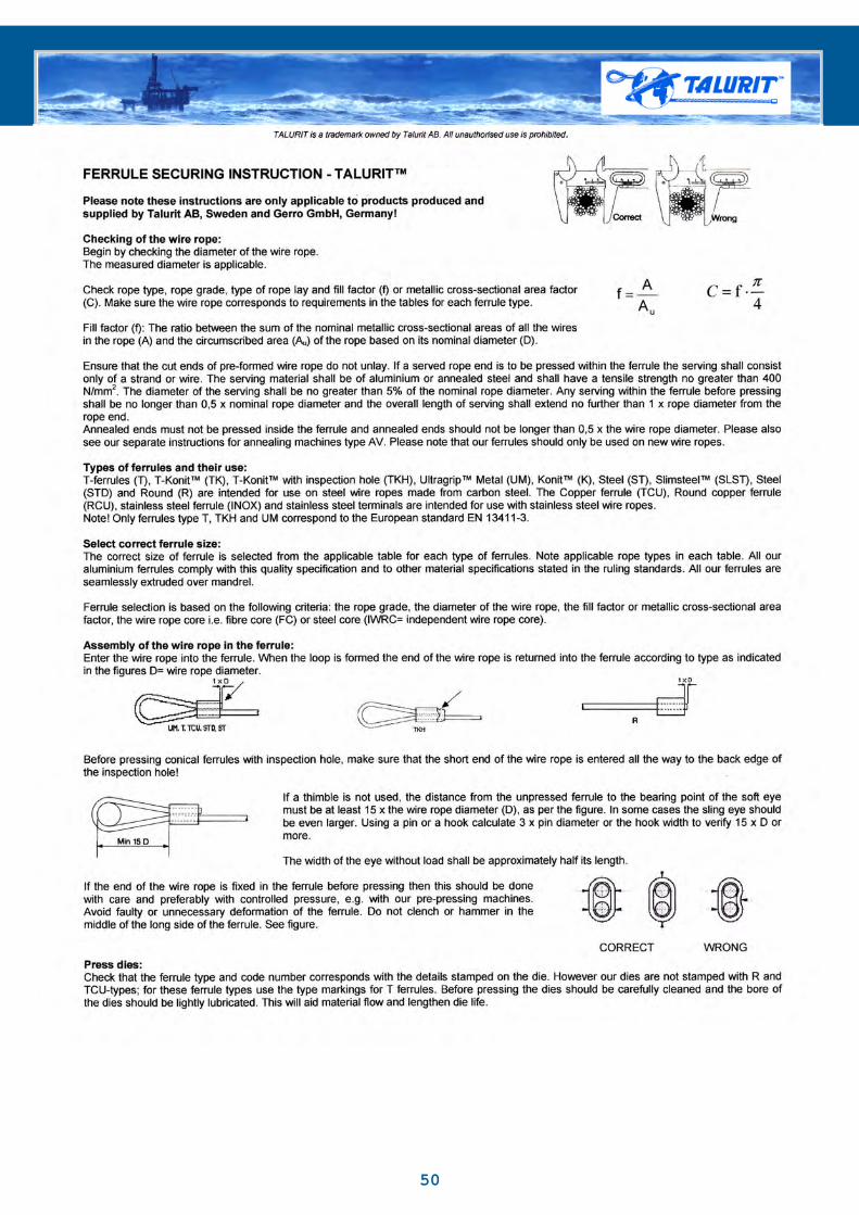
Please note that these instructions are only applicable to products produced and supplied by Talurit AB, Sweden and Gerro GmbH, Germany!
f = Fill factor, is the ratio between the sum of the nominal metallic cross-sectional areas of all the wires in the rope and the circumscribed area of the rope based on its nominal diameter.
C =Nominal metallic cross-sectional area factor of the rope.
.C = 4
Rev. 2009-01-29
Wire Rope Capacity Diameter (mm)
Ferrule No.
Fill factor(f=0,42-0,52)Fibre Core
Fill factor(f=0,53-0,58)Steel Core
Dies marked
Diameter after pressing
Required pressureapprox.
INOX Min Max Min Max INOX (mm) / Tol. (kN)
1 1,2 1,1 0,8 1,0 1 3,6 +0,10
70
1,52
2,53
3,54
4,5
1,21,72,32,83,33,84,3
1,62,22,73,23,74,24,7
1,11,52,12,73,13,64,1
1,42,02,63,03,54,04,5
1,52
2,53
3,54
4,5
4,24,856
7,88
9,8
+0,150
100160200250300350400
56789
4,85,56,57,58,5
5,46,47,48,49,5
4,65,16,27,28,2
5,06,17,18,19,1
56789
10,812141618
+0,30
500600700850
1 000
10111213
9,610,611,612,7
10,511,512,613,6
9,210,211,212,3
10,111,112,213,2
10111213
2021,32426
+0,40
1 1001 3501 5001 750
1416
13,714,7
14,616,7
13,314,3
14,216,2
1416
2832
+0,50
2 0002 500
182022
16,819,121,1
19,021,023,1
16,318,320,3
18,220,222,2
182022
364044
+0,60
3 1003 4003 900
24262830
23,225,327,429,5
25,227,329,431,5
22,324,326,528,5
24,226,428,430,3
24262830
48525660
+0,80
4 5005 0005 6006 000
GTS015GTS02GTS025GTS03GTS035GTS04GTS045GTS05GTS06GTS07GTS08GTS09GTS10GTS11GTS12GTS13GTS14GTS16
Code
GTS18GTS20GTS22GTS24GTS26GTS28GTS30
52

Round ferrule (R)(aluminium)
Copper ferrule (TCU)(copper)
Round copper ferrule (RCU)(copper)
© 2009, Talurit AB
Talurit AB · Amalia Jönssons gata 29 · 421 31 Västra Frölunda · Sweden · VAT SE556343720001Phone +46 31 709 30 80 · Fax +46 31 47 10 71 · [email protected] · www.talurit.com
TALURIT is a trademark owned by Talurit AB. All unauthorised use is prohibited.
TALURITTM SPLICING SYSTEMTable of sizes for R, RCU, TCU and TCUK ferrules
Please note that these instructions are only applicable to products produced and supplied by Talurit AB, Sweden and Gerro GmbH, Germany!
Ferrules have been validated according to TALURIT™ splicing system, which is within the frames of EN 13411-3. Copper as material is not accepted in this standard.
Ferrules made of copper (RCU, TCU and TCUK) are intended for use with stainless steel
TCU and TCUK: We do not guarantee strength of slings for lifting activities made of Copper turn-back ferrules. A termination performed according to our instructions will normally withstand a tensile strength of 90% of minimum breaking load (MBL) of the
Ends stops (R and RCU) are not allowed to use for lifting applications. The expected strength regarding this end-termination is approximately 50% of the MBL of the wire rope (informative only). Accordingly, verifying tests must be performed to secure the strength of the application.
Wire rope: Above table applies to bright or galvanized single layer steel wire ropes with round strands and rope grade 1 570 – 1 960. Wire ropes shall conform to EN 12385-4 and 5. The types of rope shall be Ordinary or Lang lay. For higher tensile grade and higher Fill factor, please contact our Technical Department.
Please refer to TALURIT Ferrule Securing Instruction for further information.
Rev. 2009-09-22
f = Fill factor, is the ratio between the sum of the nominal metallic cross-sectional areas of all the wires in the rope and the circumscribed area of the rope based on its nominal diameter.
C =Nominal metallic cross-sectional area factor of the rope.
. C = 4
Wire Rope Capacity Diameter (mm)
Ferrule No. Fill factor(f=0,40-0,50)Fibre Core
Fill factor(f=0,50-0,60)Steel Core
Dies marked
Diameter after pressing
Required pressureapprox.
R RCU TCU TCUK Min Max Min Max T (mm) / Tol. (kN)
1.5 1.51
1.50,91,1
1,01,5
0,81,0
0,91,4
11,5
33,8
+0,10
1020
2
3
4
5
2
3
4
5
22.53
3.54
4.55
1,62,12,73,23,74,24,7
2,02,63,13,64,14,65,1
1,52,02,52,93,43,94,3
1,92,42,83,33,84,24,7
22,53
3,54
4,55
45678910
+0,10
30456080100125180
66.5789
6
78
66.5789
89
5,26,26,77,28,3
6,16,67,18,29,0
4,85,76,26,77,6
5,66,16,67,58,2
66,5789
1213141618
+0,30
210250320410500
10111213
10111213
10111213
9,110,211,312,4
10,111,212,313,4
8,39,3
10,311,3
9,210,211,212,2
10111213
20222426
+0,40
600720850
1 000
1416
1416
1416
13,514,6
14,516,1
12,313,3
13,214,7
1416
2832
+0,50
1 3001 600
182022
182022
182022
16,218,320,3
18,220,222,4
14,816,718,5
16,618,420,4
182022
364044
+0.60
2 0002 4002 900
242628
24
28
24 22,524,727,0
24,626,928,6
20,522,624,7
22,524,626,1
242628
485256
+0.80
3 4003 9004 500
3032
30 28,730,9
30,832,7
26,228,2
28,129,9
3032
6064
+1.00
5 1005 800
GTC02GTCO25GTC03GTC035GTC04GTC045GTC05GTC06GTC065GTC07GTC08GTC09GTC10GTC11GTC12GTC13
GTC24GTC26GTC28
Copper Ferrule
GTC015 1,1 1,5 1,0 1,4 1,5 3,8 0 20
Ferrule SizeCode No:
GTC14GTC16GTC18GTC20GTC22
GTC30
53

© 2010, Talurit AB
Talurit AB · Amalia Jönssons gata 29 · 421 31 Västra Frölunda · Sweden · VAT SE556343720001Phone +46 31 709 30 80 · Fax +46 31 47 10 71 · [email protected] · www.talurit.com
TALURIT is a trademark owned by Talurit AB. All unauthorised use is prohibited.Rev. 2010-05-17
Lengthafterpressingapprox.
T TKH T/TKH2,5 2,5 2,7 2,5 5 +0,2 12 303 2,8 3,2 2,5 2,7 3 6 0 14 453,5 3,3 3,7 2,8 3,2 3,5 7 16 604 3,8 4,3 3,3 3,7 4 8 18 804,5 4,4 4,8 3,8 4,3 4,5 9 20 1005 4,9 5,4 4,4 4,8 3,8 4,3 5 10 23 1256 5,5 6,4 4,9 5,4 4,4 4,8 6 12 +0,4 27 1806,5 6,5 6,9 5,5 6,4 4,9 5,4 6,5 13 0 29 2107 7,0 7,4 6,5 6,9 6,0 6,4 5,5 6,4 7 14 32 2508 8 7,5 8,4 7,0 7,4 6,5 6,9 6,5 6,9 8 16 36 3209 9 8,5 9,5 7,5 8,4 7,0 7,9 7,0 7,4 9 18 40 41010 10 9,6 10,5 8,5 9,5 8,0 8,9 7,5 8,4 10 20 +0,5 45 50011 11 10,6 11,6 9,6 10,5 9,0 9,9 8,5 9,5 11 22 0 50 60012 12 11,7 12,6 10,6 11,6 10,0 10,9 9,6 10,5 12 24 54 72013 13 12,7 13,7 11,7 12,6 11,0 11,9 10,6 11,6 13 26 59 85014 14 13,8 14,7 12,7 13,7 12,0 12,9 11,7 12,6 14 28 +0,7 63 1 00016 16 14,8 16,8 13,8 14,7 13,0 13,9 12,7 13,7 16 32 0 72 1 30018 18 16,9 18,9 14,8 16,8 14,0 15,9 13,8 14,7 18 36 +0,9 81 1 60020 20 19,0 21,0 16,9 18,9 16,0 17,9 14,8 16,8 20 40 0 90 2 00022 22 21,1 23,1 19,0 21,0 18,0 19,9 16,9 18,9 22 44 99 2 40024 24 23,2 25,2 21,1 23,1 20,0 21,9 19,0 21,0 24 48 +1.1 108 2 90026 26 25,3 27,3 23,2 25,2 22,0 23,9 21,1 23,1 26 52 0 117 3 40028 28 27,4 29,4 25,3 27,3 24,0 25,9 23,2 25,2 28 56 126 3 90030 30 29,5 31,5 27,4 29,4 26,0 27,9 25,3 27,3 30 60 +1,4 135 4 50032 32 31,6 33,6 29,5 31,5 28,0 29,9 27,4 29,4 32 64 0 144 5 10034 34 33,7 35,7 31,6 33,6 30,0 31,9 29,5 31,5 34 68 153 5 80036 36 35,8 37,8 33,7 35,7 32,0 33,9 31,6 33,6 36 72 +1,6 162 6 50038 38 37,9 39,9 35,8 37,8 34,0 35,9 33,7 35,7 38 76 0 171 7 20040 40 40,0 42,0 37,9 39,9 36,0 37,9 35,8 37,8 40 80 180 8 00044 44 42,1 46,2 40,0 42,0 38,0 39,9 37,9 39,9 44 88 +1,9 198 9 70048 48 46,3 50,4 42,1 46,2 40,0 43,9 40,0 43,9 48 96 0 216 11 50052 52 50,5 54,6 46,3 50,4 44,0 47,9 44,0 47,9 52 104 +2.1
0234 13 500
56 56 54,7 58,8 50,5 54,6 48,0 51,9 48,0 50,4 56 112 +2.3 0
252 15 700
60 60 58,9 63,0 54,7 58,8 52,0 54,6 50,5 54,6 60 120 +2.4 0
270 18 000
FERRULE SELECTION CHART ACCORDING TO EN 13411-3Page 1(2)
Measured Wire RopeDiameter Range (mm)
Ferrule size / Code No.
Case 1Fill factor
Case 2Fill factor
Case 3Fill factor
Case 4Fill factor
Diesmarked
Diameterafterpressing
Lengthafterpressingapprox.
Requiredpressure approx.
T TKH Min Max Min Max Min Max Min Max T/TKH mm Tol mm kN
Table corresponds to EN 13411-3: 2004 + A1: 2008
Code
GTA44GTA48
GTA56
GTA60
GTA56
ALUMINIUM FERRULES
GTA14GTA16GTA18GTA20GTA22GTA24GTA26GTA28GTA30GTA32GTA34GTA36GTA38GTA40
GTA025GTA03GTA035GTA04GTA045GTA05GTA06GTA065GTA07GTA08GTA09GTA10GTA11GTA12GTA13
DIN codes 1.5 (GTA), 2 (GTA02), 42 (GTA42), are still available on request, however these sizes are not includedin the EN13411-3 standards.
54

55

CODEWIRE ROPE SIZE
FIBRE CORE STEEL CORE(FC)mm (IWRC)mm
DIE SIZEDIN BS
DIA AFTER PRESS
GTR03A 2.7 - 3.1 2.5 - 2.8 3 2.5 6GTR04A 3.7 - 4.1 3.4 - 3.8 4 3.5 8GTR05A 4.7 - 5.1 4.3 - 4.7 5 4.5 10GTR06A 5.2 - 6.1 4.8 - 5.6 6 - 12GTR08A 7.2 - 8.2 6.7 - 7.5 8 7 16GTR10A 9.1 - 10.1 8.3 - 9.2 10 9 20GTR12A 11.3 - 12.3 10.3 - 11.2 12 11 24GTR13A 12.4 - 13.4 11.3 - 12.2 13 12 26GTR14A 13.5 - 14.5 12.3 - 13.2 14 13 28GTR16A 14.6 - 16.1 13.3 - 14.7 16 15 32GTR18A 16.2 - 18.2 14.8 - 16.6 18 17 36
ALUMINIUM ROUND CLAMPS
PRESS CLAMPS OF CARBON STEEL
Bridco have a range of Talurit Carbon Steel Clamps and Clamps for Flemish eye available on request.
Conical Carbon Steel clamps (STK)
Cylindrical Carbon Steel clamps (ST)
Cylindrical Carbon Steel clamps (STD)
56

TALURIT is a trademark owned by Talurit AB. All unauthorised use is prohibited.
© 2010, Talurit AB
Talurit AB · Amalia Jönssons gata 29 · 421 31 Västra Frölunda · Sweden · VAT SE556343720001Phone +46 31 709 30 80 · Fax +46 31 47 10 71 · [email protected] · www.talurit.com
18 TON 1-PILLAR SWAGERTALURIT™TALURIT™ – here with a small Swager with high capacity
Rev. 2010-04-14
The 18-ton Swager has a single pillar open throat design and can be used either vertically or horizontally, bench mounted or free standing. An adjustable stand can be offered as an option.
In a single stage swage T-ferrules up to No. 6 can be swaged. Multi stage swaging makes it possible to swage T-ferrules up to No. 8. Note! All our dies are manufactured from hardened and tempered die steel for long life and durability.
Operating the pump: Close the valve on the pump and start pumping the handle to close the dies. Open the relief valve to open the dies.
SWAGER Hand pump
Art No: P 0018T 1P Art No: HAGG P23-18
Max. swaging force (kN) 180 Max. load (kN) 180
Type of die A Noise level (dB (A)) -Capacity-Single stage (T) 6 Option: Stand (Art no: 1993)-Multi stage (T) 8
Weight (kg) 24
TECHNICAL DATA
• Economically priced• Robust design• Total reliability• Easy to place• Easy to carry• Easy to use
Swager with stand
Horizontal application
Open and close the valve
57
TALURIT is a trademark owned by Talurit AB. All unauthorised use is prohibited.
© 2010, Talurit AB
Talurit AB · Amalia Jönssons gata 29 · 421 31 Västra Frölunda · Sweden · VAT SE556343720001Phone +46 31 709 30 80 · Fax +46 31 47 10 71 · [email protected] · www.talurit.com
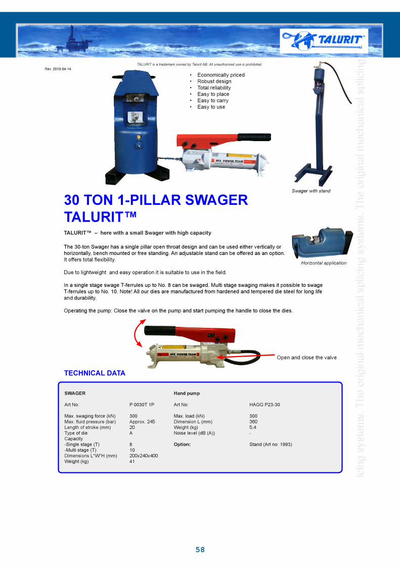
30 TON 1-PILLAR SWAGERTALURIT™TALURIT™ – here with a small Swager with high capacity
Swager with stand
Rev. 2010-04-14
The 30-ton Swager has a single pillar open throat design and can be used either vertically or horizontally, bench mounted or free standing. An adjustable stand can be offered as an option.
In a single stage swage T-ferrules up to No. 8 can be swaged. Multi stage swaging makes it possible to swage T-ferrules up to No. 10. Note! All our dies are manufactured from hardened and tempered die steel for long life and durability.
Operating the pump: Close the valve on the pump and start pumping the handle to close the dies.
SWAGER Hand pump
Art No: P 0030T 1P Art No: HAGG P23-30
Max. swaging force (kN) 300 Max. load (kN) 300
Type of die A Noise level (dB (A)) -Capacity-Single stage (T) 8 Option: Stand (Art no: 1993)-Multi stage (T) 10
Weight (kg) 41
TECHNICAL DATA
Horizontal application
• Economically priced• Robust design• Total reliability• Easy to place• Easy to carry• Easy to use
Open and close the valve
58

TALURIT is a trademark owned by Talurit AB. All unauthorised use is prohibited.
© 2009, Talurit AB
Talurit AB · Amalia Jönssons gata 29 · 421 31 Västra Frölunda · Sweden · VAT SE556343720001Phone +46 31 709 30 80 · Fax +46 31 47 10 71 · [email protected] · www.talurit.com
75 TON 1-PILLAR SWAGERTALURIT™TALURIT™ – here with a powerful and compact Swager
75-ton Swager Hydraulic unit 3,0 kW or 4,0 kW
• Economically priced• Robust design• Total reliability• User friendly• Two models
With option• Automatic return• Pressure pre-setting
Rev. 2009-12-02
The 75-ton Swager has a single pillar open throat design and can be used either vertically or horizontally, bench
The machine can swage T-ferrules up to No.11 and UM-ferrules up to No.12 in a single stage. Multi stage swaging makes it possible to swage T-ferrules up to No.16 and UM-ferrules up to No.18.Note! All our dies are manufactured from hardened and tempered die steel for long life and durability.
The swaging operation is controlled by an electric foot pedal that permits the operator to use both hands when swaging. In addition to the normal up/down function, the foot pedal has a ”hold” position to facilitate rope/eye adjustment and to make tool set-up quicker. The retraction of the piston is limited by a time delay and maximum pressure is set by a pressure valve.
When left unused the automatic shut down turns off the swager. It is easily started again by pressing the foot pedal.
By setting the required pressure on the optional pressure gauge MA 250, the piston returns automatically once the pressure is reached. This saves time and unnecessary movements for the operator.
SWAGER HYDRAULIC UNITElectrical control
Art No: P 0075T 1P Art No: HAGG EL 3,0 HAGG EL 4,0
Max. swaging force (kN) 750 Power (kW) 3,0 4,0
Length of stroke (mm) 25 Piston velocity approx. (mm/s) Approx 3,5 Approx 5,5Type of die B1 Reservoir volume (l) 30 30Capacity Inlet/outlet threads on couplings 3/8’’ 3/8’’-Single stage (T/UM) 11/12 Dimensions L*W*H (mm) 640x420x650 640x420x690-Multi stage (T/UM) 16/18 Weight (kg) 91 105Dimensions L*W*H (mm) 330x355x525 Noise level (dB (A)) 58 66Weight (kg) 140
Option:Analogue pressure gauge MA 250 MA 250
TECHNICAL DATA
59

TALURIT is a trademark owned by Talurit AB. All unauthorised use is prohibited.
© 2010, Talurit AB
Talurit AB · Amalia Jönssons gata 29 · 421 31 Västra Frölunda · Sweden · VAT SE556343720001Phone +46 31 709 30 80 · Fax +46 31 47 10 71 · [email protected] · www.talurit.com
150 TON 1-PILLAR SWAGERTALURIT™TALURIT™ – here with the most powerful Swager among the smallest
Rev. 2010-03-25
The 150-ton Swager has a single pillar open throat design and can be used either vertically or horizontally, bench
the dies.
above size 6 in serial production.
In a single stage swage T-ferrules up to No.16 and UM-ferrules up to No.18 can be swaged.
Note! All our dies are manufactured from hardened and tempered die steel for long life and durability.
The swaging operation is controlled by an electric foot pedal permitting the operator to use both hands when swaging.
By setting the required pressure on the optional pressure gauge MA 250, the piston returns automatically once the pressure is reached. This saves time and unnecessary movements for the operator.
150-ton Swager Hydraulic unit 3,0 kW or, 4,0 kW
TECHNICAL DATA
SWAGER HYDRAULIC UNITElectrical control
Art No: P 0150T 1P Art No: HAGG EL 3,0 HAGG EL 4,0 HAGG EL 5,5
Type of die B1/B2 - low pressure: app.10
Option:Electrical pressure gauge MA 250 MA 250 MA 250
• Economically priced• Robust design• Total reliability• User friendly• Two models• Automatic shut down
With option• Automatic return• Pressure pre-setting
Hydraulic unit 5,5 kW
60

© 2010, Talurit AB
Talurit AB · Amalia Jönssons gata 29 · 421 31 Västra Frölunda · Sweden · VAT SE556343720001Phone +46 31 709 30 80 · Fax +46 31 47 10 71 · [email protected] · www.talurit.com
TALURIT is a trademark owned by Talurit AB. All unauthorised use is prohibited.
600 Ton 1-Pillar SwagerTALURIT™TALURIT™ – here with swager providing ample working space
P 0600T 1M
Rev: 2010-05-19
SWAGER
Art No: P 0600T 1M Capacity (T)-single stage 34
Max. swaging capacity (kN) 6 000 -multi stage 40
Power (kW) 11 -high pressure 2.3
Length of stroke (mm) 60Reservoir volume (l) 165
Type of die D (C, C1)Dimensions L*W*H (mm) 1 850 x 800 x 1 870
Option Working height (mm) 1 180
Noise level 75 dB(A)
TECHNICAL DATA
of maintenance.
When left un-used the resource saving automatic shut down will turn off the machine. Press down the foot pedal to start again.
61

62
63

© 2010, Talurit AB
Talurit AB · Amalia Jönssons gata 29 · 421 31 Västra Frölunda · Sweden · VAT SE556343720001Phone +46 31 709 30 80 · Fax +46 31 47 10 71 · [email protected] · www.talurit.com
TALURIT is a trademark owned by Talurit AB. All unauthorised use is prohibited.
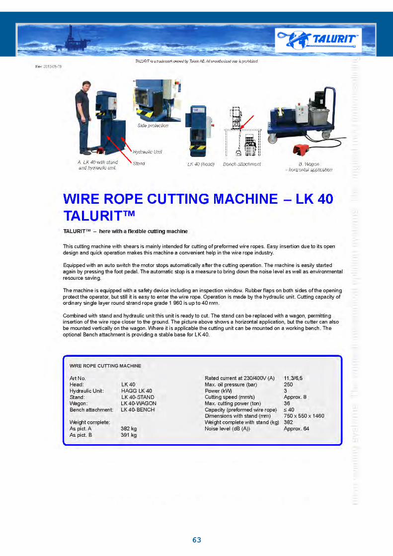
WIRE ROPE CUTTING MACHINE – LKS 40 and LKS 60TALURIT™TALURIT™ – here with a durable and user friendly cutter
LKS 60 LKS 40 with measuring unit MA 40
Exhaust pipe
Rev: 2010-05-19
These cutting machines are intended to cut steel wire ropes up to 40 respective 60 mm diameter.
Cutting is done with a disc (4800 rpm). The machine gives the wire rope a very good cut.
With an optional length measuring unit the machine can measure wire rope up to 40 mm diameter.
Optimize your production line with the following optional machines; Uncoiling Unit Measuring Unit Coiling Machine
WIRE ROPE CUTTING MACHINE
Art No: LKS 40 LKS 60
Dimensions L*W*H (mm) 940 x 560 x 1700 1050 x 560 x 1700
Cutting speed (mm/s) 20 mm / 2 sec 20 mm / 2 sec40 mm / 5 sec 40 mm / 5 sec
60 mm / 15 secRated current at 230V / 400V 14,5A / 7,5A 14,5A / 7,5ANoise level (dB(A)) 95 (approx.) 95 (approx.)
OPTIONS Art No:Uncoiling Unit AVL-3000, AVL-6000Measuring Unit MA 40Coiling Machine UL 800, UL 1200
TECHNICAL DATA
64

© 2010, Talurit AB
Talurit AB · Amalia Jönssons gata 29 · 421 31 Västra Frölunda · Sweden · VAT SE556343720001Phone +46 31 709 30 80 · Fax +46 31 47 10 71 · [email protected] · www.talurit.com
TALURIT is a trademark owned by Talurit AB. All unauthorised use is prohibited.
LKA 26-PS Automatic Cutting MachineTALURIT™TALURIT™ – Automatic Cutting Machine type LKA 26-PS for 10-26 mm diameter wire rope
LKA 26-PS
LKA 26-PS with spout
Rev: 2010-05-21
Fully Automatic Cutting Machine
Art No: LKA 26-PS
Rated Current at 400 V 16 A Feeding power max. 100 kgMax oil pressure 170 bar Cutting cycle 5 s (approx.)Hydraulic motor power 3 kW Feeding speed 0-400 mm/sFeeding motor power 0.75 kW Capacity Ø 10-26 mmPneumatic working pressure 4-7 bar Dimensions L*W*H (mm) 1 615 x 740 x 1 510
Weight 850 kg
Option Noise level 73 dB(A) (approx.)3 m spout Art no. 300Compressor for pneumatic supply Art no. 300
TECHNICAL DATA
LKA 26-PS is a fully automatic cutting machine for wire ropes. The feeding unit is equipped with slow start and soft retardation of the feeding speed before cut for high precision. This machine is intended for cutting pre-formed wire ropes and the capacity is Ø 10-26 mm.
Two independent measuring systems are standard to ensure very high accuracy. This machine has a very low noise level and is environmentally friendly. The spout and feeding units are operated pneumatically. 9 m spout is included as standard. Sections of 3 m spouts can be added as option.
Hydraulic shears perform the cutting operation. Three shears with different cutting bores enable highest quality cut of the wire rope.
As option we can offer a separate compressor for pneumatic supply.
65

66
Press DiesHeight (mm) Width (mm) Intended for
Type A 38 42 18t,22t,25t and 30t presses
Type B 48 50 50t presses
Type B1 48 70 75t, 100t, 150t presses
Type C 78 80 250t, and 300t presses (and larger presses with die holder)
Type C1 78 100 250t and 300t presses ( and larger presses with die holder)
Type D 110 156 500t and 600t presses ( and larger presses with die holder)
Type E 150 220 900t and 1000t presses (and larger presses with die holders)
Type F 200 250 1500t presses (and larger presses with die holder)
Type G 250 300 2000t presses (and larger presses with die holder)
Type H 300 380 3000t presses (and larger presses with die holder)
Type of die holder Length (mm) Width (mm) Height (mm) Weight (kgArticle no:VIN C/D 200 156 102 30VIN C/D EXC 200 156 102 26VIN C1/D 200 156 102 30VIN D/E LIN 280 220 127 60VIN E/F 350 250 152 77VIN E/G 350 305 222 206VIN F/G 430 305 152 135VIN F/H 400 375 250 320VIN G/H 450 380 202 186
Press Capacity (ton) Die Holders
600t C/D (EXC), C1/D1000T C/D (EXC). C1/D, D/E1500T D/E, E/F2000T D/E, E/G, F/G3000T D/E, E/G, F/H, G/H