coplanar waveguide with top and bottom shields in place of air-bridges
TRANSCRIPT

IEEE TRANSACTIONS ON MICROWAVE THEORY AND TECHNIQUES, VOL. 41, NO. 9, SEPTEMBER 1993 1559
Coplanar Waveguide with Top and Bottom Shields in Place of Air-Bridges
A.A. Omar and Y. L. Chow, Member, IEEE
Abstract- A convenient technique for the elimination of the coupled slot-line mode in coplanar waveguide (CPW) nonsym- metric circuits is proposed. This technique simply uses top and/or bottom ground plane shields and avoids the more costly air- bridges. These shields are easy to fabricate, however, may slightly affect the propagation of the CPW mode in the form of power leakage into the parallel plate TEM mode. This effect can be avoided by restricting operation to lower frequencies. Numerical comparisons between the effect of the shields and the air-bridges on a CPW filter are presented.
I. INTRODUCTION HE coplanar waveguide (CPW) has attracted attention in T the past few years due to its appealing properties such
as the low dispersion, low radiation and the ease of shunt and series connections [ 11. However, the main obstacle facing CPW is the excitation of the parasitic (odd) slot-line mode in nonsymmetric CPW circuits, like T-junctions, due to the different path length traversed by the magnetic current (electric field) waves in the adjacent slots. This parasitic mode tends to radiate and must therefore be eliminated or reduced.
The conventional method for eliminating the parasitic slot- line mode has been through the use of air-bridges [2]. How- ever, these air-bridges are potentially costly to build, especially in large CPW circuits where a large number of these air- bridges may be needed [2].
In this paper, we propose the use of top andlor bottom ground plane shields to eliminate the parasitic coupled slot- line mode in CPW without air-bridges. This method relies on the fact that the fields, generated by the unidirectional mag- netic currents of the parasitic coupled slot-line mode, decay relatively slowly and are therefore significantly affected by the top and/or bottom ground plane shields. These shields tend to generate an infinite number of magnetic current images which have the same amplitude and direction as the slot magnetic currents of the parasitic mode. This increases the magnetic impedance for the slot-line mode which causes this mode to be essentially eliminated. On the contrary, the fields due to the dominant CPW mode, of opposite magnetic currents, decay relatively quickly and are therefore only slightly affected by the shields.
In addition to the elimination of the slot-line mode, several other advantages can be gained from the use of bottom
Manuscript received September 14, 1992; revised March 1, 1993. The authors are with the Department of Electrical and Computer Engineer-
ing, University of Waterloo, Waterloo, Ontario, Canada, N2L 3G1. Currently, A. A. Omar is with Communications Research Centre Ottawa, Ontario, Canada K2H 852.
IEEE Log Number 9211861.
Fig. 1. The top view of the CPW band reject filter with the original air-bridge of [5] indicated (dimensions are in pm).
shielding for CPW. These advantages are: the reduction of the characteristic impedance, the improvement of the mechanical strength of the substrate, the reduction of the dispersion, the easier implementation of the CPW-microstrip transitions and the easier grounding of floating regions [4].
The main disadvantage which may be expected from the proposed method of eliminating the parasitic mode is the power leakage from the dominant CPW mode into the parallel plate TEM mode caused by the shields [1],[3], [4]. This problem must, therefore, be avoided for the proposed method of elimination to be successful.
In Section I1 we briefly explain our theoretical formulation for the CPW with ground plane shields. In Section I11 we study numerically the effect of the shields, top, bottom individual or together, on the elimination of the coupled slot-line mode by solving for the S-parameters of a CPW band reject filter whose top view is shown in Fig. 1, and whose cross section is shown in Fig. 2.
11. THEORETICAL FORMULATION
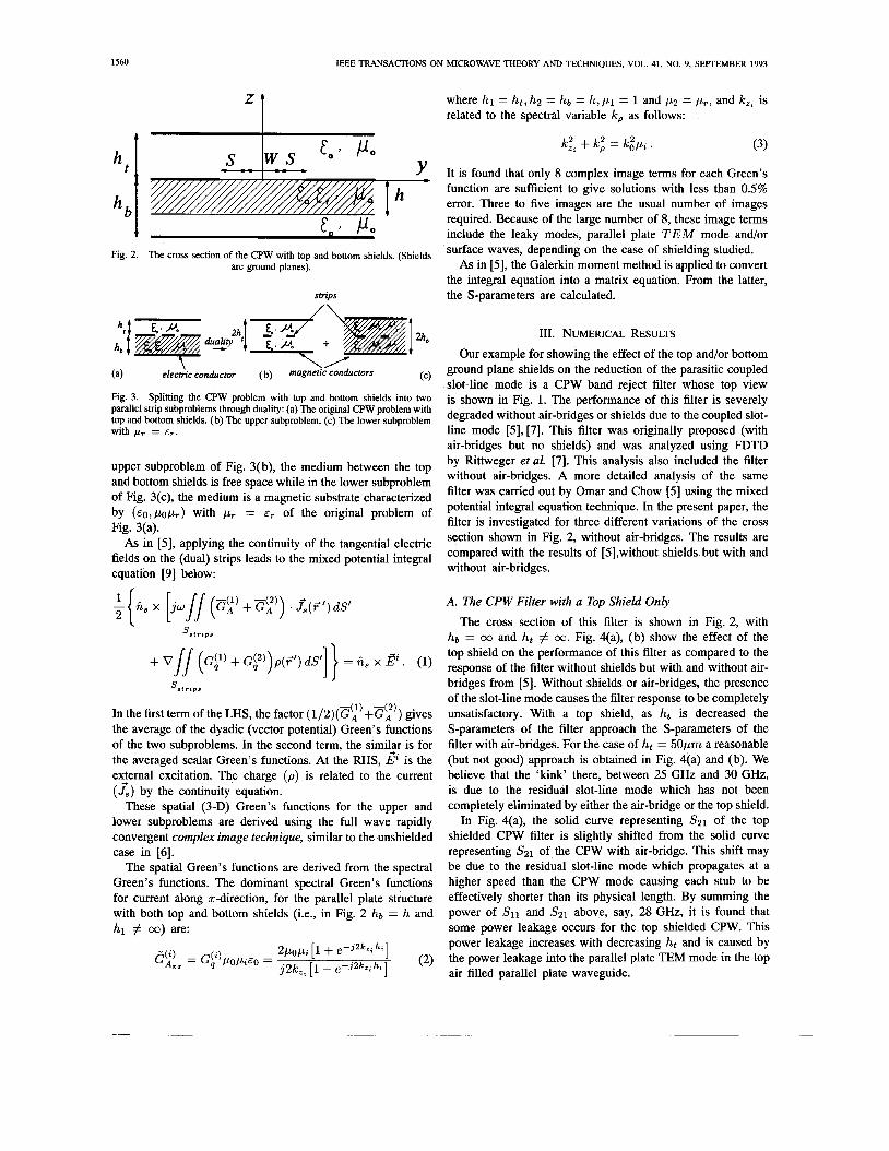
In this section, we formulate the CPW with both top and bottom ground plane shields, whose cross section is shown in Fig. 2 with hb = h and ht # 00, where ht,hb are the top and bottom shield heights, respectively, and h is the substrate thickness. This formulation is similar to the formulation for the CPW without shields in [5].
The duality principle [5] is used to convert the CPW problem with top and bottom shields into two parallel (dual) strip subproblems with each subproblem embedded between two parallel magnetic shields as shown in Fig. 3(a)-(c). In the
0018-9480/93$03.00 0 1993 IEEE
1560 IEEE TRANSACTIONS ON MICROWAVE THEORY AND TECHNIQUES, VOL. 41, NO. 9, SEPTEMBER 1993
t h
hb
Fig. 2.
Y Iuo
c-’ P o
The cross section of the CPW with top and bottom shields. (Shields are ground planes).
where hl = ht, h 2 = h b = h, p 1 = 1 and p 2 = p r , and kz, is related to the spectral variable k, as follows:
(3)
It is found that only 8 complex image terms for each Green’s function are sufficient to give solutions with less than 0.5% error. Three to five images are the usual number of images required. Because of the large number of 8, these image terms include the leaky modes, parallel plate TEM mode and/or surface waves, depending on the case of shielding studied.
As in [5], the Galerkin moment method is applied to convert the integral equation into a matrix equation. From the latter,
strips the S-parameters are calculated.
111. NUMERICAL RESULTS
Our example for showing the effect of the top and/or bottom \ \A ground plane shields on the reduction of the parasitic coupled
slot-line mode is a CPW band reject filter whose top view (a) electric conductor (b) magnefic COnduCtOrs (‘)
Fig. 3. Splitting the CPW problem with top and bottom shields into two parallel strip subproblems through duality: (a) The original CPW problem with top and bottom shields. (b) The upper subproblem. (c) The lower subproblem
is shown in Fig. 1. The performance of this filter is severely degraded without air-bridges Or due to the coup1ed ’lot-
with pr = E ~ . line mode [5],[7]. This filter was originally proposed (with air-bridges but no shields) and was analyzed using FDTD
upper subproblem of Fig. 3(b), the medium between the top and bottom shields is free space while in the lower subproblem of Fig. 3(c), the medium is a magnetic substrate characterized by ( E O , popT) with pr = ET of the original problem of Fig. 3(a).
As in [5], applying the continuity of the tangential electric fields on the (dual) strips leads to the mixed potential integral equation [9] below:
by Rittweger et al. 171. This analysis also included the filter without air-bridges. A more detailed analysis of the same filter was carried out by Omar and Chow [5] using the mixed potential integral equation technique. In the present paper, the filter is investigated for three different variations of the cross section shown in Fig. 2, without air-bridges. The results are compared with the results of [5],without shields but with and without air-bridges.
In the first term of the LHS, the factor (1/2)(G$)+G$)) gives the average of the dyadic (vector potential) Green’s functions of the two subproblems. In the second term, the simikr is for the averaged scalar Green’s functions. At the RHS, E% is the exiemal excitation. The charge ( p ) is related to the current ( Js) by the continuity equation.
These spatial (3-D) Green’s functions for the upper and lower subproblems are derived using the full wave rapidly convergent complex image technique, similar to the unshielded case in [6] .
The spatial Green’s functions are derived from the spectral Green’s functions. The dominant spectral Green’s functions for current along z-direction, for the parallel plate structure with both top and bottom shields @e., in Fig. 2 h b = h and hl # 03) are:
A. The CPW Filter with a Top Shield Only The cross section of this filter is shown in Fig. 2, with
ha = 03 and ht # 03. Fig. 4(a), (b) show the effect of the top shield on the performance of this filter as compared to the response of the filter without shields but with and without air- bridges from [5]. Without shields or air-bridges, the presence of the slot-line mode causes the filter response to be completely unsatisfactory. With a top shield, as ht is decreased the S-parameters of the filter approach the S-parameters of the filter with air-bridges. For the case of ht = 50pm a reasonable (but not good) approach is obtained in Fig. 4(a) and (b). We believe that the ‘kink’ there, between 25 GHz and 30 GHz, is due to the residual slot-line mode which has not been completely eliminated by either the air-bridge or the top shield.
In Fig. 4(a), the solid curve representing Sal of the top shielded CPW filter is slightly shifted from the solid curve representing ,921 of the CPW with air-bridge. This shift may be due to the residual slot-line mode which propagates at a higher speed than the CPW mode causing each stub to be effectively shorter than its physical length. By summing the power of ,911 and S 2 1 above, say, 28 GHz, it is found that some power leakage occurs for the top shielded CPW. This power leakage increases with decreasing ht and is caused by the power leakage into the parallel plate TEM mode in the top air filled parallel plate waveguide.

OMAR AND CHOW: COPLANAR WAVEGUIDE WITH TOP AND BOTTOM SHIELDS 1561
1.0
0.8
- p . 5
m -
0.3
0.0
1 .o
0.8
- 3 5 v3 -
o s
0.0
0 10 eo SO 40
FREQUENCY (GHz) (a)
- wlth oirbridgc (no 8hWda) [ - h=sopm - - without airbridge or ahirldr ?3]
I / .' i
V
Fig. 4. A comparison between the S-parameters of the filter without shields but with and without air-bridges ( [5 , Fig. lo]) and the S-parameters of the filter with top shield and no air-bridges. (a) 15211. (b) 15111. (E,. = 9.8, h = 635pm, h b = co, ht = 50pm other dimensions are shown in Fig. 1).
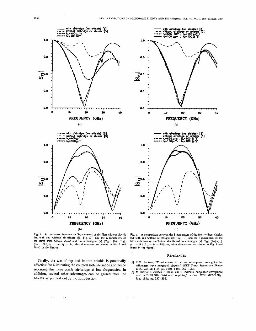
B. The CPW Filter with Bottom Shield Only The cross section of this filter is shown in Fig. 2, with
hb = h and ht = 00. The response of this filter for different di- electric thicknesses (hb) is shown in Fig. 5(a), (b). This figure shows that as hb becomes smaller, the scattering parameters of the filter with bottom shield approach satisfactorily those
for the filter without shields but with air-bridges. This signifies that the coupled slot-line mode has been substantially reduced by the bottom shield.
It is of interest to observe that the agreement between the two solid curves in Fig. 5(a), (b) is very good for frequencies below 28 GHz. Above this frequency a more significant power loss occurs. This power loss results from leaking energy from the dominant CPW mode into the parallel plate TEM mode this time in the bottom dielectric. This leakage also causes the small differences in 1,511 I between the two solid curves in Fig. 5( b).
C. The CPW with Both Top and Bottom Shields The cross section of this filter is shown in Fig. 2, with
hb = h and ht # 00. Fig. 6(a), (b) shows that the filter with both the top and bottom shields at the low heights of 100pm, has a response that is nearly the same as that with an air-bridge. With the top shield at 635,um, there is a slight reduction in the band reject characteristics at 19 GHz. The results of Figs. 4,5, and 6 for the filters with top and/or bottom shields, show that the bottom shield is substantially more effective in eliminating the slot-line mode than the top shield. However, to closely approach the effectiveness of the air-bridge, both the top and bottom shields are to be at 100,um heights or lower.
Fig. 6 also reveals that there is some power leakage from the CPW mode into the TEM modes both in the air and dielectric filled parallel plate waveguides above and below the slots, respectively. This power leakage occurs mainly at frequencies greater than 28 GHz and is comparable to that with only a bottom shield of Fig. 5. This indicates the small effect of the top shield on the leakage when ht 2 100pm. However, for ht < 50pm, reducing the top shield height is found to noticeably increase the power leakage.
The small difference in ,511 between the shielded filter and the filter with air-bridges in Fig. 6, is due to the power leakage into both the upper and lower parallel plate regions.
IV. CONCLUSIONS
To eliminate the parasitic coupled slot-line mode in coplanar waveguide nonsymmetric circuits, we suggest to use top andlor bottom ground plane shields which can substantially reduce the parasitic mode without significantly affecting the dominant CPW mode.
Bottom shielding is found to be more effective in elimi- nating the slot-line mode than top shielding. However, for effectively replacing the air-bridge, both the top and bottom shields should be placed as close as possible from the slots (ht , hb = h < W + 2s in Fig. 2), but before they adversely reduce the characteristic impedance of the CPW line.
The power leakage into the parallel plate TEM mode either in the dielectric or air can be reduced by operating the filter at low frequencies at which h b = h < X,/25, where A, is the guide wavelength, and also by using smaller slot or strip widths [3], [4].
1562
1.0 -
0.8 -
- 3* - m -
0.9 -
IEEE TRANSACTIONS ON MICROWAVE THEORY AND TECHNIQUES, VOL. 41, NO. 9, SEPTEMBER 1993
1 .o
0.8
- with airbridge (no Dhidds) [5 . - - without airbridge or rhieldr [I] e u n
3 . 5 ul -
0.9
0.0
0 10 m 30 40
FREQUENCY (CHz) (a)
- with oirbridge (no rhiolds) [5 . - - without airbridge or rhieldr [I] -- h ~ ~ 4 0 0 p L m - hb-100”
0.0 I-*, ,. , , ,. , , , (
0 10 m 30 40
FREQUENCY (CHz) ( b)
Fig. 5. A comparison between the S-parameters of the filter without shields but with and without air-bridges ([5, Fig. lo]) and the S-parameters of the filter with bottom shield and no air-bridges. (a) ISzll. (b) IS111. ( E ~ = 9.8 ,h t = w , h b = h, other dimensions are shown in Fig. 1 and listed in the figure).
1 .o
0.8
- 9 . 5 m -
0.9
0.0
1 .o
0.8
- 3 . 5 m -
O J
0.0
0 10 80 30 40
FREQUENCY (CHz) (a)
0 10 m 30 10
FREQUENCY (GIiz) ( b)
Fig. 6. A comparison between the S-parameters of the filter without shields but with and without air-bridges ( [5 , Fig. lo]) and the S-parameters of the filter with both top and bottom shields and no air-bridges. (a) IS21 I. (b) 1.911 I. (E,. = 9.8,hb = h = 100pm, other dimensions are shown in Fig. 1 and listed in the figure).
REFERENCES the Of top and bottom is potentially [ l ] R.W. Jackson, “Consideration in the use of coplanar waveguide for
effective for eliminating the coupled slot-line mode and hence replacing the more costly air-bridge at low frequencies. In addition, several other advantages can be gained from the shields as pointed out in the Introduction.
millimeter wave integrated circuits,” IEEE Trans. Microwave Theory
[2] M. Riaziat, I. Zubeck, S. Band, and G. Zdasiuk, “Coplanar waveguides used in 2-18 GHz distributed in proc. IEEE M n - s Dig., June 1986, pp. 337-338.
vOl. Mm-349 PP. 1450-1456, Dee. 1986.

OMAR AND CHOW COPLANAR WAVEGUIDE WITH TOP AND BO’ITOM SHIELDS 1563
[3] H. Shigesawa, M. Tsuji and A. A. Oliner, “Conductor-backed slot line and coplanar waveguide: Dangers and full-wave analyses,” in Proc. IEEE MTT-S Dig., 1988, pp. 199-202.
[4] Dayalan P. Kasilingam and David B. Rutledge, “Surface wave losses of coplanar transmission lines,” in Pmc. IEEE MTT-S Dig., 1983, pp. 113-116.
[5] A. A. Omar and Y. L. Chow, “A solution of coplanar waveguide with air- bridges using complex images,” IEEE Trans. Microwave Theory Tech.,
[6] A.A. Omar and Y.L. Chow, “Complex image Green’s functions for coplanar waveguides,” in Proc. IEEE AP-S Dig., 1992, pp. 1496-1499.
[7] M. Rittweger, M. Abdo, and I. Wolff, “Full-wave analysis of coplanar discontinuities considering three dimensional bond wires,” in Proc. IEEE MTT-S Dig., 1991, pp. 465-468.
VOI. MIIT-40, pp. 2070-2077, NOV. 1992.
A.A. Omar was born in Kuwait, on December 15, 1963. He received the B.Sc. and M.Sc. degrees from Kuwait University, Kuwait, in 1985 and 1988, respectively. Currently he is working towards the Ph.D. degree at the University of Waterloo, Waterloo, ON, Canada.
From 1985 to 1989 he was a Research and a Teaching Assistant with the Department of Electrical and Computer Engineering, Kuwait University. From 1989 to 1993 he studied and obtained the Ph.D. degree in electrical and computer engineering from the University of Waterloo. Currently, he is a visiting researcher at the Communication Research Centre, Ottawa, ON, Canada. His research interests are in the numerical solution of microwave and millimeter-wave integrated circuits.
Y. L. Chow, (S’60-M’65) received the B.Eng. degree in 1960 from McGill University, Montreal, PQ, Canada, and the M.A.Sc. and Ph.D. degrees in 1961 and 1965 from the University of Toronto, Toronto, ON, Canada.
From 1964 to 1966, be worked for the National Radio Astronomy Obser- vatory, Charlottesville, VA. As a consequence, in 1974 he designed the array configuration for the Very Large Antenna Array, which comprises 27 85-ft parabolic reflectors and is located in Socorro, NM. In 1966 he joined the University of Waterloo, Waterloo, ON, Canada, and became a Professor in the Department of Electrical and Comuter Engineering. Presently his research deals with the numerical simulation of field effects. The field effects range from high-voltage dc fields to antennas and to fields of microwave integrated circuits, both linear and nonlinear. In the microwave integrated circuit area, he is a consultant to both the Communication Research Centre, Canada, and EEsof Inc., California. He is the principal author of the field-theory-based MIC package EMsim. of EEsof Inc.