cop 3530: computer science iii summer 2005 graphs and graph algorithms – part 7
DESCRIPTION
COP 3530: Computer Science III Summer 2005 Graphs and Graph Algorithms – Part 7. Instructor : Mark Llewellyn [email protected] CSB 242, 823-2790 http://www.cs.ucf.edu/courses/cop3530/summer05. School of Computer Science University of Central Florida. - PowerPoint PPT PresentationTRANSCRIPT
COP 3530: Graphs – Part 7 Page 1 © Mark Llewellyn
COP 3530: Computer Science IIISummer 2005
Graphs and Graph Algorithms – Part 7
School of Computer ScienceUniversity of Central Florida
Instructor : Mark Llewellyn [email protected]
CSB 242, 823-2790http://www.cs.ucf.edu/courses/cop3530/
summer05
COP 3530: Graphs – Part 7 Page 2 © Mark Llewellyn
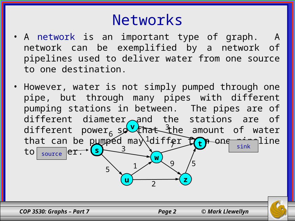
Networks• A network is an important type of graph. A network can be
exemplified by a network of pipelines used to deliver water from one source to one destination.
• However, water is not simply pumped through one pipe, but through many pipes with different pumping stations in between. The pipes are of different diameter and the stations are of different power so that the amount of water that can be pumped may differ from one pipeline to another.
ws
v
u
t
z
3
9
13
76
515
2
sourcesink
COP 3530: Graphs – Part 7 Page 3 © Mark Llewellyn
Networks (cont.)
ws
v
u
t
z
3
9
13
76
515
2
sourcesink
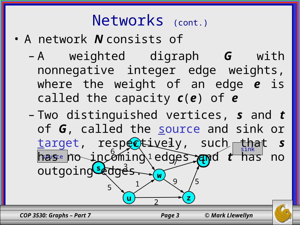
• A network N consists of– A weighted digraph G with nonnegative integer
edge weights, where the weight of an edge e is called the capacity c(e) of e
– Two distinguished vertices, s and t of G, called the source and sink or target, respectively, such that s has no incoming edges and t has no outgoing edges.
COP 3530: Graphs – Part 7 Page 4 © Mark Llewellyn
Networks (cont.)
tu
v
s
w
z
3
9
13
76
515
2source
sink
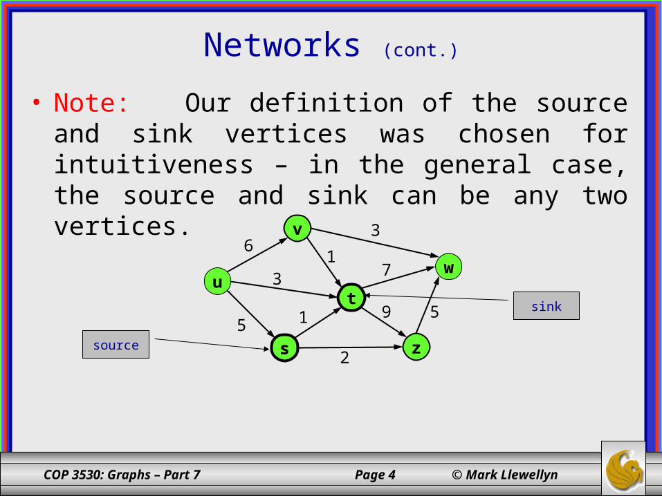
• Note: Our definition of the source and sink vertices was chosen for intuitiveness – in the general case, the source and sink can be any two vertices.
COP 3530: Graphs – Part 7 Page 5 © Mark Llewellyn
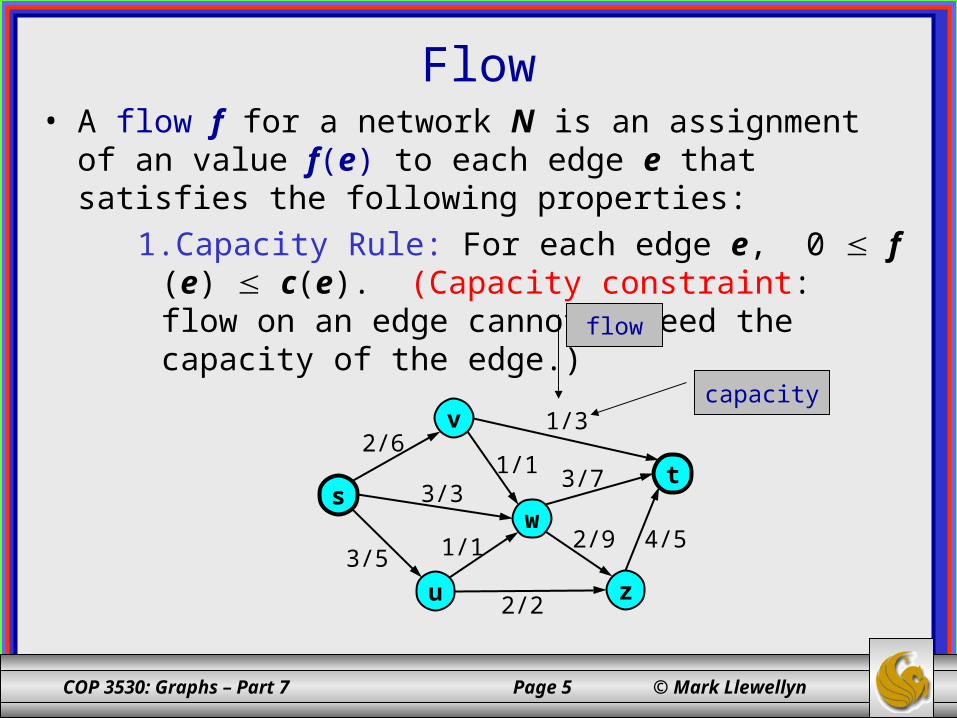
Flow• A flow f for a network N is an assignment of an value f(e) to
each edge e that satisfies the following properties:1.Capacity Rule: For each edge e, 0 f (e) c(e).
(Capacity constraint: flow on an edge cannot exceed the capacity of the edge.)
ws
v
u
t
z
3/3
2/9
1/1
1/3
3/72/6
4/51/13/5
2/2
flow
capacity
COP 3530: Graphs – Part 7 Page 6 © Mark Llewellyn
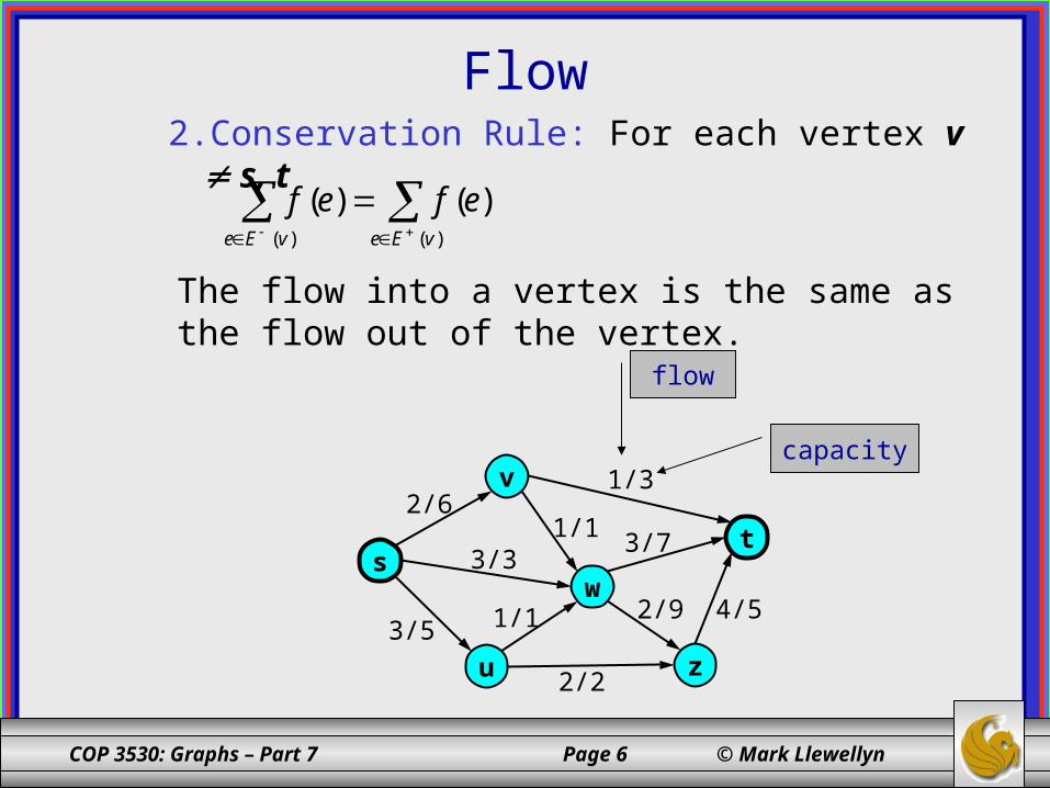
Flow2. Conservation Rule: For each vertex v s, t
ws
v
u
t
z
3/3
2/9
1/1
1/3
3/72/6
4/51/13/5
2/2
flow
capacity
)()(
)()(vEevEe
efef
The flow into a vertex is the same as the flow out of the vertex.
COP 3530: Graphs – Part 7 Page 7 © Mark Llewellyn
The Maximum Flow Problem
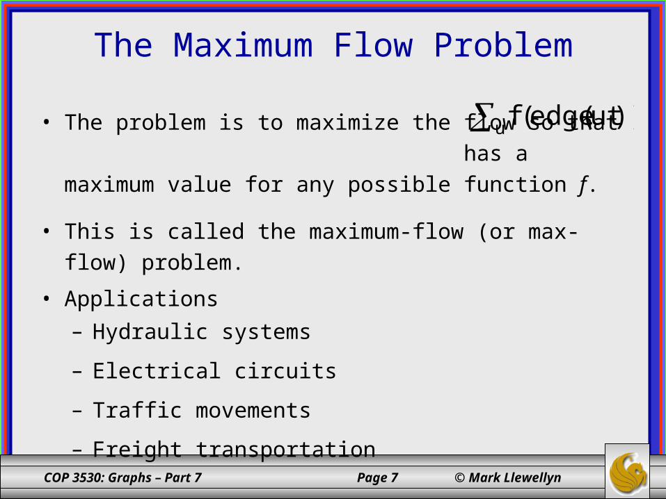
• The problem is to maximize the flow so that has a maximum value for any possible function f.
• This is called the maximum-flow (or max-flow) problem.
• Applications– Hydraulic systems
– Electrical circuits
– Traffic movements
– Freight transportation
u ))ut(edge(f
COP 3530: Graphs – Part 7 Page 8 © Mark Llewellyn
The Maximum Flow Problem (cont.)
ws
v
u
t
z
3/3
2/9
1/1
1/3
3/72/6
4/51/13/5
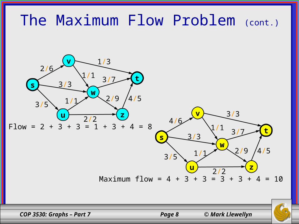
2/2Flow = 2 + 3 + 3 = 1 + 3 + 4 = 8
ws
v
u
t
z
3/3
2/9
1/1
3/3
3/74/6
4/51/13/5
2/2Maximum flow = 4 + 3 + 3 = 3 + 3 + 4 = 10
COP 3530: Graphs – Part 7 Page 9 © Mark Llewellyn
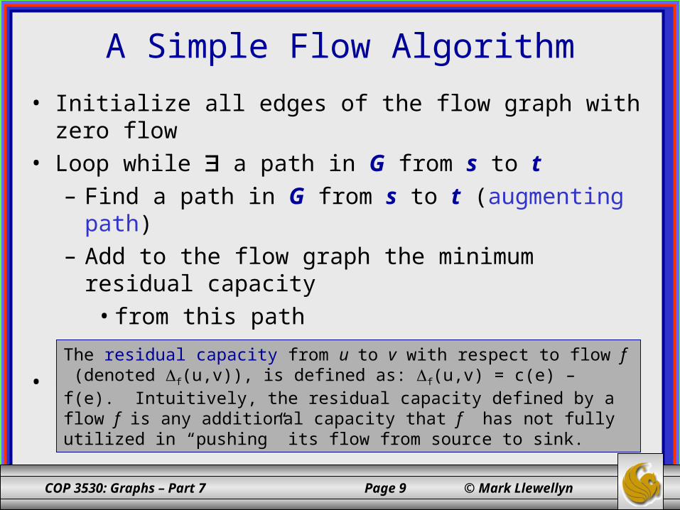
A Simple Flow Algorithm• Initialize all edges of the flow graph with zero flow• Loop while a path in G from s to t
– Find a path in G from s to t (augmenting path)– Add to the flow graph the minimum residual capacity
• from this path– Reduce the residual capacity of the edges
• end Loop
The residual capacity from u to v with respect to flow f (denoted f(u,v)), is defined as: f(u,v) = c(e) – f(e). Intuitively, the residual capacity defined by a flow f is any additional capacity that f has not fully utilized in “pushing” its flow from source to sink.
COP 3530: Graphs – Part 7 Page 10 © Mark Llewellyn
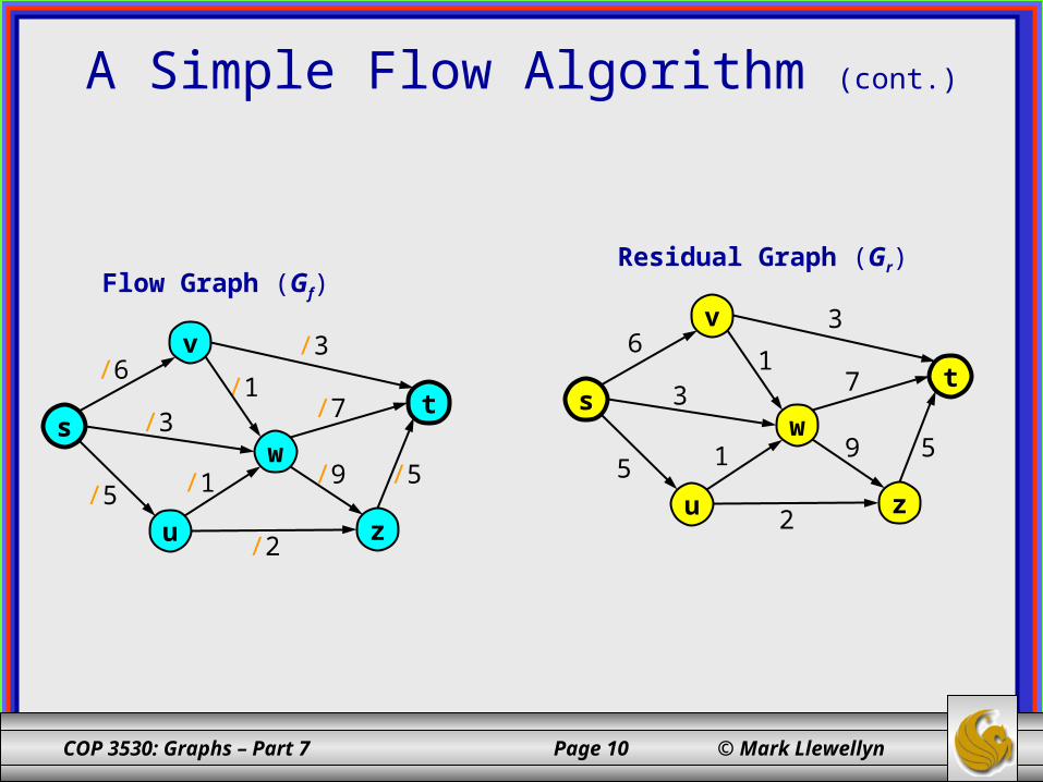
A Simple Flow Algorithm (cont.)
ws
v
u
t
z
/3
/9
/1/3
/7/6
/5/1/5
/2
Flow Graph (Gf)Residual Graph (Gr)
ws
v
u
t
z
3
9
13
76
515
2
COP 3530: Graphs – Part 7 Page 11 © Mark Llewellyn
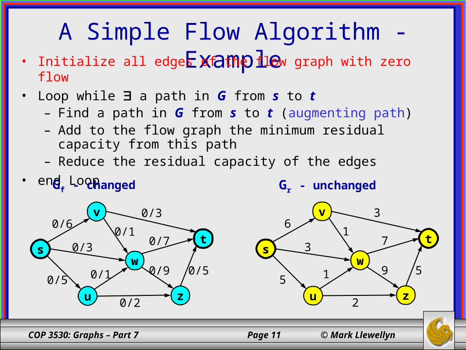
A Simple Flow Algorithm - Example• Initialize all edges of the flow graph with zero flow• Loop while a path in G from s to t
– Find a path in G from s to t (augmenting path)– Add to the flow graph the minimum residual capacity from this path– Reduce the residual capacity of the edges
• end Loop
ws
v
u
t
z
0/3
0/9
0/10/3
0/70/6
0/50/10/5
0/2
Gf - changed Gr - unchanged
ws
v
u
t
z
3
9
13
76
515
2

COP 3530: Graphs – Part 7 Page 12 © Mark Llewellyn
A Simple Flow Algorithm - Example• Initialize all edges of the flow graph with zero flow• Loop while a path in G from s to t
– Find a path in G from s to t (augmenting path)– Add to the flow graph the minimum residual capacity from this path– Reduce the residual capacity of the edges
• end Loop
ws
v
u
t
z
0/3
0/9
0/10/3
0/70/6
0/50/10/5
0/2
Gf - unchanged Gr - changed
ws
v
u
t
z
3
9
13
76
515
2
COP 3530: Graphs – Part 7 Page 13 © Mark Llewellyn
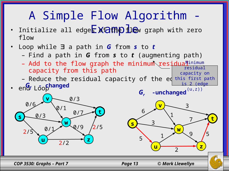
A Simple Flow Algorithm - Example• Initialize all edges of the flow graph with zero flow• Loop while a path in G from s to t
– Find a path in G from s to t (augmenting path)– Add to the flow graph the minimum residual capacity from this path– Reduce the residual capacity of the edges
• end Loop
ws
v
u
t
z
0/3
0/9
0/10/3
0/70/6
2/50/12/5
2/2
Gf - changedGr -unchanged
ws
v
u
t
z
3
9
13
76
515
2
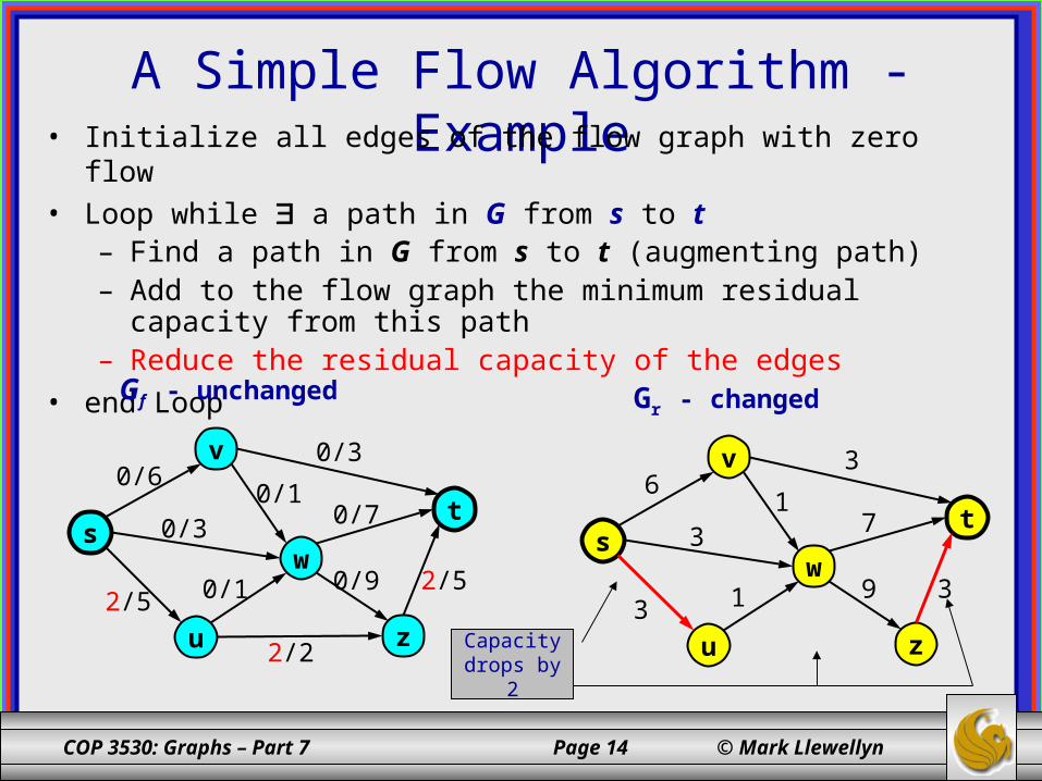
Minimum residual capacity on this
first path is 2 (edge (u,z))
COP 3530: Graphs – Part 7 Page 14 © Mark Llewellyn
A Simple Flow Algorithm - Example• Initialize all edges of the flow graph with zero flow• Loop while a path in G from s to t
– Find a path in G from s to t (augmenting path)– Add to the flow graph the minimum residual capacity from this path– Reduce the residual capacity of the edges
• end Loop
ws
v
u
t
z
0/3
0/9
0/10/3
0/70/6
2/50/12/5
2/2
Gf - unchanged Gr - changed
ws
v
u
t
z
3
9
13
76
313Capacity drops by
2
COP 3530: Graphs – Part 7 Page 15 © Mark Llewellyn
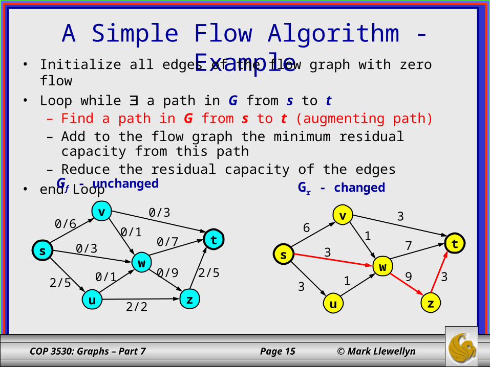
A Simple Flow Algorithm - Example• Initialize all edges of the flow graph with zero flow• Loop while a path in G from s to t
– Find a path in G from s to t (augmenting path)– Add to the flow graph the minimum residual capacity from this path– Reduce the residual capacity of the edges
• end Loop
ws
v
u
t
z
0/3
0/9
0/10/3
0/70/6
2/50/12/5
2/2
Gf - unchanged Gr - changed
ws
v
u
t
z
3
9
13
76
313

COP 3530: Graphs – Part 7 Page 16 © Mark Llewellyn
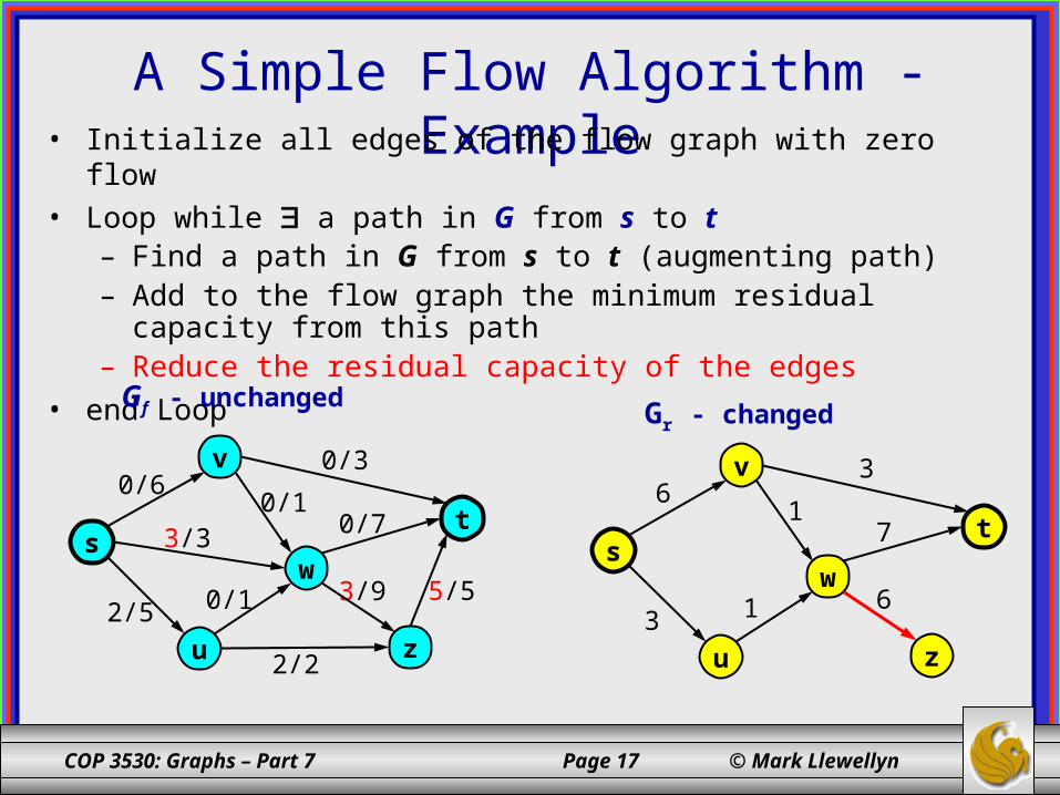
A Simple Flow Algorithm - Example• Initialize all edges of the flow graph with zero flow• Loop while a path in G from s to t
– Find a path in G from s to t (augmenting path)– Add to the flow graph the minimum residual capacity from this path– Reduce the residual capacity of the edges
• end Loop
ws
v
u
t
z
3/3
3/9
0/10/3
0/70/6
5/50/12/5
2/2
Gf - changed Gr - unchanged
ws
v
u
t
z
3
9
13
76
313
Minimum residual capacity on this
first path is 3 (edge (s,w))
COP 3530: Graphs – Part 7 Page 17 © Mark Llewellyn
A Simple Flow Algorithm - Example• Initialize all edges of the flow graph with zero flow• Loop while a path in G from s to t
– Find a path in G from s to t (augmenting path)– Add to the flow graph the minimum residual capacity from this path– Reduce the residual capacity of the edges
• end Loop
ws
v
u
t
z
3/3
3/9
0/10/3
0/70/6
5/50/12/5
2/2
Gf - unchanged Gr - changed
ws
v
u
t
z
6
13
76
13
COP 3530: Graphs – Part 7 Page 18 © Mark Llewellyn
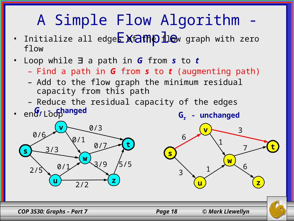
A Simple Flow Algorithm - Example• Initialize all edges of the flow graph with zero flow• Loop while a path in G from s to t
– Find a path in G from s to t (augmenting path)– Add to the flow graph the minimum residual capacity from this path– Reduce the residual capacity of the edges
• end Loop
ws
v
u
t
z
3/3
3/9
0/10/3
0/70/6
5/50/12/5
2/2
Gf - changed Gr - unchanged
ws
v
u
t
z
6
13
76
13
COP 3530: Graphs – Part 7 Page 19 © Mark Llewellyn
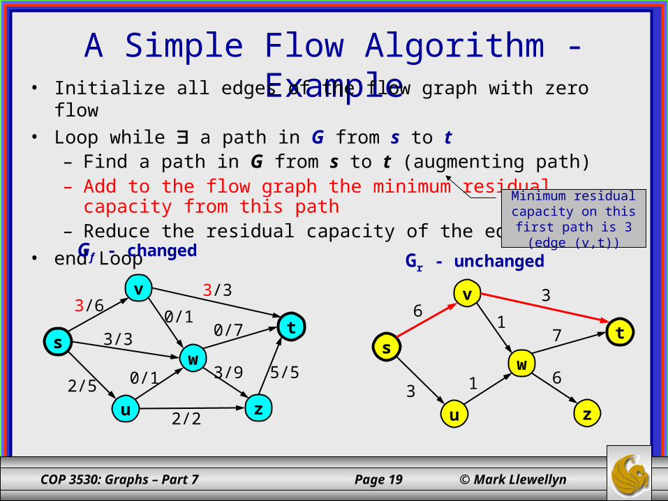
A Simple Flow Algorithm - Example• Initialize all edges of the flow graph with zero flow• Loop while a path in G from s to t
– Find a path in G from s to t (augmenting path)– Add to the flow graph the minimum residual capacity from this path– Reduce the residual capacity of the edges
• end Loop
ws
v
u
t
z
3/3
3/9
0/13/3
0/73/6
5/50/12/5
2/2
Gf - changed Gr - unchanged
ws
v
u
t
z
6
13
76
13
Minimum residual capacity on this
first path is 3 (edge (v,t))
COP 3530: Graphs – Part 7 Page 20 © Mark Llewellyn
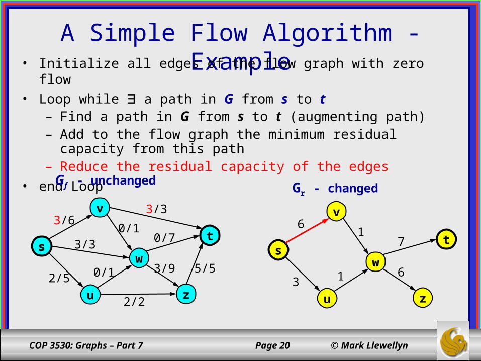
A Simple Flow Algorithm - Example• Initialize all edges of the flow graph with zero flow• Loop while a path in G from s to t
– Find a path in G from s to t (augmenting path)– Add to the flow graph the minimum residual capacity from this path– Reduce the residual capacity of the edges
• end Loop
ws
v
u
t
z
3/3
3/9
0/13/3
0/73/6
5/50/12/5
2/2
Gf - unchanged Gr - changed
ws
v
u
t
z
6
17
6
13
COP 3530: Graphs – Part 7 Page 21 © Mark Llewellyn
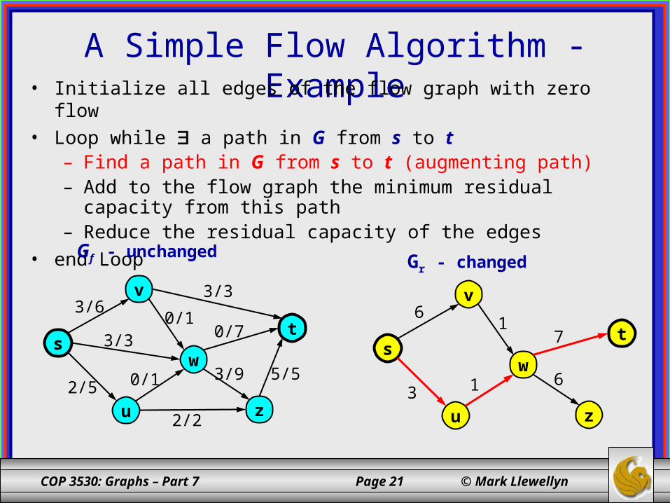
A Simple Flow Algorithm - Example• Initialize all edges of the flow graph with zero flow• Loop while a path in G from s to t
– Find a path in G from s to t (augmenting path)– Add to the flow graph the minimum residual capacity from this path– Reduce the residual capacity of the edges
• end Loop
ws
v
u
t
z
3/3
3/9
0/13/3
0/73/6
5/50/12/5
2/2
Gf - unchanged Gr - changed
ws
v
u
t
z
6
17
6
13

COP 3530: Graphs – Part 7 Page 22 © Mark Llewellyn
A Simple Flow Algorithm - Example• Initialize all edges of the flow graph with zero flow• Loop while a path in G from s to t
– Find a path in G from s to t (augmenting path)– Add to the flow graph the minimum residual capacity from this path– Reduce the residual capacity of the edges
• end Loop
ws
v
u
t
z
3/3
3/9
0/13/3
1/73/6
5/51/13/5
2/2
Gf - changed Gr - unchanged
ws
v
u
t
z
6
17
6
13
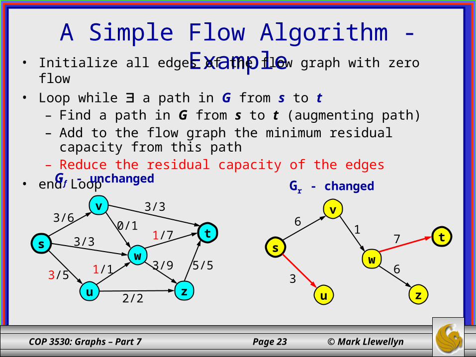
Minimum residual capacity on this
first path is 1 (edge (u,w))
COP 3530: Graphs – Part 7 Page 23 © Mark Llewellyn
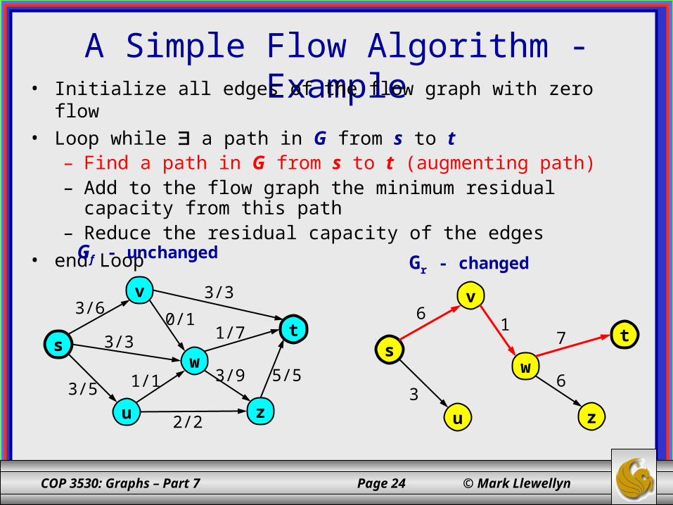
A Simple Flow Algorithm - Example• Initialize all edges of the flow graph with zero flow• Loop while a path in G from s to t
– Find a path in G from s to t (augmenting path)– Add to the flow graph the minimum residual capacity from this path– Reduce the residual capacity of the edges
• end Loop
ws
v
u
t
z
3/3
3/9
0/13/3
1/73/6
5/51/13/5
2/2
Gf - unchanged Gr - changed
ws
v
u
t
z
6
17
6
3
COP 3530: Graphs – Part 7 Page 24 © Mark Llewellyn
A Simple Flow Algorithm - Example• Initialize all edges of the flow graph with zero flow• Loop while a path in G from s to t
– Find a path in G from s to t (augmenting path)– Add to the flow graph the minimum residual capacity from this path– Reduce the residual capacity of the edges
• end Loop
ws
v
u
t
z
3/3
3/9
0/13/3
1/73/6
5/51/13/5
2/2
Gf - unchanged Gr - changed
ws
v
u
t
z
6
17
6
3
COP 3530: Graphs – Part 7 Page 25 © Mark Llewellyn
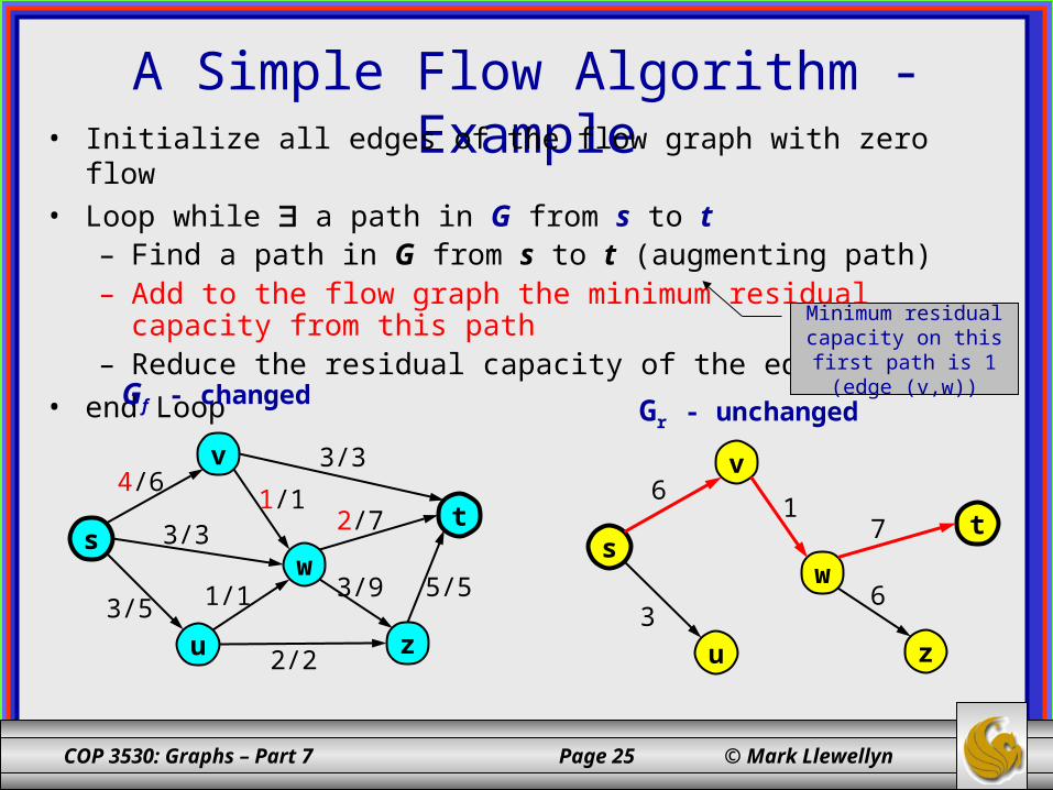
A Simple Flow Algorithm - Example• Initialize all edges of the flow graph with zero flow• Loop while a path in G from s to t
– Find a path in G from s to t (augmenting path)– Add to the flow graph the minimum residual capacity from this path– Reduce the residual capacity of the edges
• end Loop
ws
v
u
t
z
3/3
3/9
1/13/3
2/74/6
5/51/13/5
2/2
Gf - changed Gr - unchanged
ws
v
u
t
z
6
17
6
3
Minimum residual capacity on this
first path is 1 (edge (v,w))
COP 3530: Graphs – Part 7 Page 26 © Mark Llewellyn
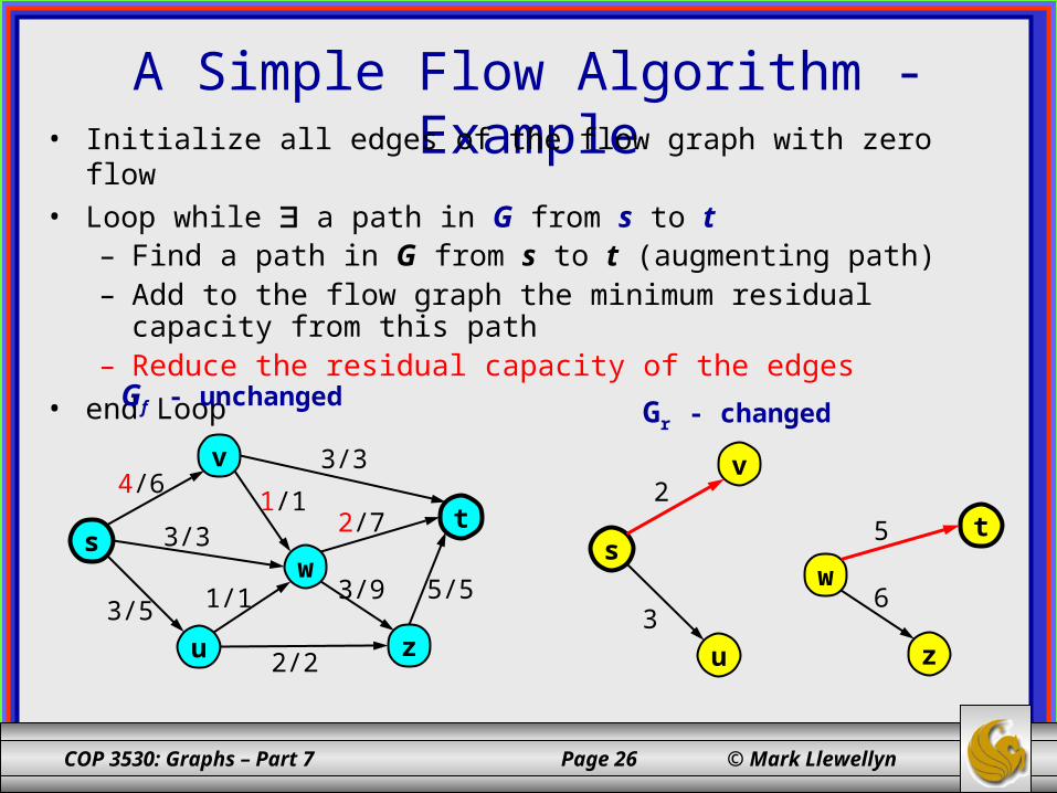
A Simple Flow Algorithm - Example• Initialize all edges of the flow graph with zero flow• Loop while a path in G from s to t
– Find a path in G from s to t (augmenting path)– Add to the flow graph the minimum residual capacity from this path– Reduce the residual capacity of the edges
• end Loop
ws
v
u
t
z
3/3
3/9
1/13/3
2/74/6
5/51/13/5
2/2
Gf - unchanged Gr - changed
ws
v
u
t
z
6
52
3
COP 3530: Graphs – Part 7 Page 27 © Mark Llewellyn
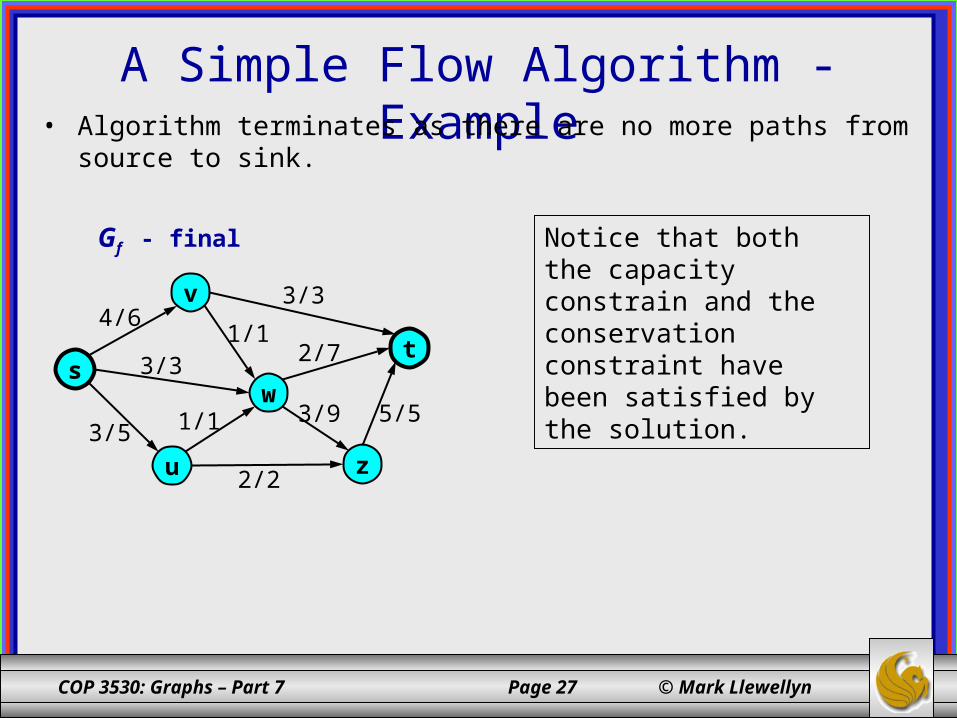
A Simple Flow Algorithm - Example• Algorithm terminates as there are no more paths from source to sink.
ws
v
u
t
z
3/3
3/9
1/13/3
2/74/6
5/51/13/5
2/2
Gf - final Notice that both the capacity constrain and the conservation constraint have been satisfied by the solution.
COP 3530: Graphs – Part 7 Page 28 © Mark Llewellyn
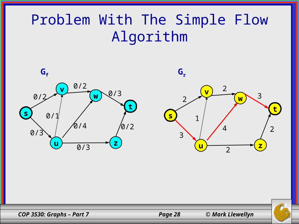
Problem With The Simple Flow Algorithm
Gf
w
s
v
u
t
z
0/20/30/2
0/20/40/3
0/3
0/1
Gr
w
s
v
u
t
z
232
243
2
1
COP 3530: Graphs – Part 7 Page 29 © Mark Llewellyn
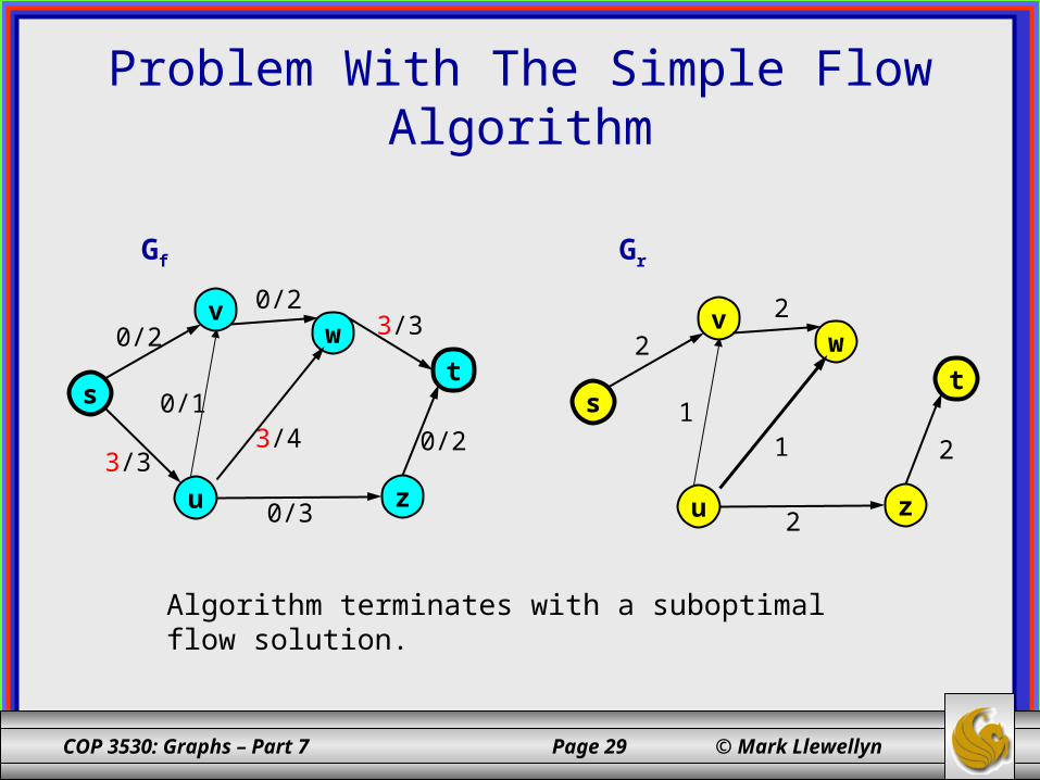
Problem With The Simple Flow Algorithm
Gf
w
s
v
u
t
z
0/23/30/2
0/23/43/3
0/3
0/1
Gr
w
s
v
u
t
z
22
21
2
1
Algorithm terminates with a suboptimal flow solution.
COP 3530: Graphs – Part 7 Page 30 © Mark Llewellyn
Cuts• It turns out that flows are closely related to another concept,
known as cuts.
• Intuitively, a cut is a division of the vertices of a flow network N into two sets, with the source on one side and the sink on the other.
• Formally, a cut of N is a partition X = (Vs, Vt) of the vertices of N such that s Vs and t Vt.
• An edge e of N with origin u Vs and destination v Vt is said to be a forward edge of cut X. An edge with origin in Vt and a destination in Vs is said to be a backward edge of cut X.
• Envision a cut as a separation of s and t in N done by cutting across edges of N, with forward edges going from s’s side to t’s side and backward edges going in the opposite direction.
COP 3530: Graphs – Part 7 Page 31 © Mark Llewellyn
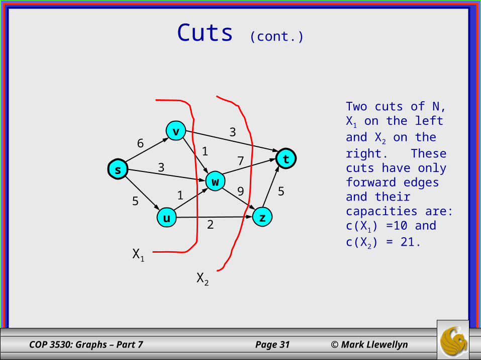
Cuts (cont.)
ws
v
u
t
z
3
9
13
76
515
2
X1
X2
Two cuts of N, X1 on the left and X2 on the right. These cuts have only forward edges and their capacities are: c(X1) =10 and c(X2) = 21.
COP 3530: Graphs – Part 7 Page 32 © Mark Llewellyn
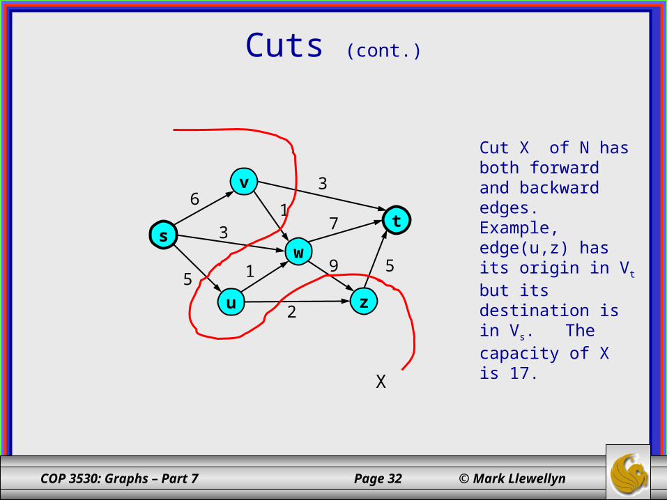
Cuts (cont.)
ws
v
u
t
z
3
9
13
76
515
2
X
Cut X of N has both forward and backward edges. Example, edge(u,z) has its origin in Vt but its destination is in Vs. The capacity of X is 17.
COP 3530: Graphs – Part 7 Page 33 © Mark Llewellyn
Cuts (cont.)
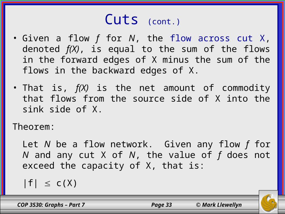
• Given a flow f for N, the flow across cut X, denoted f(X), is equal to the sum of the flows in the forward edges of X minus the sum of the flows in the backward edges of X.
• That is, f(X) is the net amount of commodity that flows from the source side of X into the sink side of X.
Theorem:
Let N be a flow network. Given any flow f for N and any cut X of N, the value of f does not exceed the capacity of X, that is:
|f| c(X)