coordinated part delivery using distributed planning
TRANSCRIPT

Coordinated Part Delivery using Distributed
Planning
by
Adrienne Bolger
B.S., Massachusetts Institute of Technology (2009)
MASSACHUSETTS INST1'UTEOF TECHNOLOGY
AUG 2 4 2010
LIBRARIES
Submitted to the Department of Electrical Engineering and ComputerScience
in partial fulfillment of the requirements for the degree of
Master of Engineering in Computer Science and Engineering
at the
MASSACHUSETTS INSTITUTE OF TECHNOLOGY
February 2010
© Massachusetts Institute of Technology 2010. All rights reserved.
A uthor ..... ......................Department of Electrical Engineering and Computer Science
February 2010
Certified by.......................... .................Daniela Rus
ProfessorThesis Supervisor
Accepted by .....\ 1"
Dr. Christopher J. TermanChairman, Department Committee on Graduate Theses
ARCHIVES

2

Coordinated Part Delivery using Distributed Planning
by
Adrienne Bolger
Submitted to the Department of Electrical Engineering and Computer Scienceon February 2010, in partial fulfillment of the
requirements for the degree ofMaster of Engineering in Computer Science and Engineering
Abstract
In this thesis, we develop a distributed mobile robot platform to deliver parts arounda model construction site. The platform's robots, specialized into delivery robotsand assembly robots, use a distributed coverage algorithm to determine where partsshould be delivered. The robots consist of a mobility platform (iRobot iCreate), a ma-nipulation platform (Crustcrawler arm), and an IR communication system to enablerecognition and grasping of parts. To control the robot hardware, we implementedsoftware in Java. The delivery robots use IR communication to find parts at a supplystation. After communicating over UDP multicast with assembly station robots, thedelivery robots deliver parts to the assembly robots based on their coverage controlalgorithm. To evaluate the algorithm, we constructed a hardware system of 4 robots,connected to a VICON motion capture system for localization. We discuss the resultsof successful hardware and software testing of the system as a method of deliveringparts around a construction site, and we discuss future plans to use the platform toassemble parts once delivered.
Thesis Supervisor: Daniela RusTitle: Professor

4

Acknowledgments
I would like to acknowledge the Boeing Corporation for their sponsorship of my
research and that of the rest of the CSAIL Distributed Robotics Laboratory. Thanks
are also due to Professor Daniela Rus for her invaluable guidance over the course
of this project. Finally, I would like to acknowledge SeungKook Yun (Ph.D. '10) ,
Lauren White (M.Eng. '10), David Stein (B. S. '10), and Matt Faulkner (M.Eng.
'09) for their previous and continuing work on the software and hardware of the
Robotic Assembly project. I could not have done this alone.

6

Contents
1 Introduction
1.1 Problem M otivation . . . . . . . . . . . . . . . . . . . . . . . . . . .. -
1.2 Contributions . . . . . . . . . . . . . . . . . . . . . . . . . . . . . ..
1.3 T hesis O utline . . . . . . . . . . . . . . . . . . . . . . . . . . . . . . .
2 Related Work in Distributed Robotic Construction
2.1 A Distributed Control Algorithm for Assembly and Manufacture . . .
2.2 Current Industrial Distributed Robotic Systems . . . . . . . . . . . .
3 Modeling a Distributed Manufacturing System
3.1 Modeling Building Components with Smart Parts
3.2 Modeling Tools and Part Delivery ...........
3.2.1 Specialized Delivery Robots ............
3.2.2 Delivery without Completely Connected Robot
3.3 Modeling the Assembly of the Structure . . . . . . .
3.3.1 Assembly Robot Load Balancing . . . . . . .
3.3.2 Assembly Robot Part Manipulation . . . . . .
3.4 Proposed Solution to the Model Problem . . . . . . .
29
. . . . . . . . . 30
. . . . . . . . . 32
. . . . . . . . . 32
Communication 32
. . . . . . . . . 33
. . . . . . . . . 33
. . . . . . . . . 33
. . . . . . . . . 34
4 System Design and Control
4.1 Inter-Robot Controller... . . . . . . . . . . . . . . . . . . . . . . .
4.1.1 Overall Algorithm . . . . . . . . . . . . . . . . . . . . . . . . .
4.1.2 Construction Blueprint . . . . . . . . . . . . . . . . . . . . . .
17
17
19
20
23
23
25

4.1.3
4.2 Single
4.2.1
4.2.2
4.2.3
4.2.4
4.2.5
Inter-Robot Communication . .
Robot Control . . . . . . . . . .
Delivery Robot Task Planning
Assembly Robot Task Planning
Part Manipulation . . . . . . .
Localization and Navigation . .
Communication . . . . . . . . .
5 System Hardware
5.1 Robot Hardware . . . . . . . . . .
5.1.1 B ase . . . . . . . . . . . . .
5.1.2 Arm Manipulation . . . . .
5.1.3 Sensing and Communicating
5.1.4 Development Platform . . .
5.2 Localization Hardware . . . . . . .
with Parts.
6 System Evaluation and Testing 59
6.1 Communication Protocol Unit Testing . . . . . . . . . . . . . . . . . 59
6.2 Full Platform Testing . . . . . . . . . . . . . . . . . . . . . . . . . . . 62
6.2.1 Setup . . . . . . . . . . . . . . . . . . . . . . . . . . . . . . . 62
6.2.2 Scenario Completion . . . . . . . . . . . . . . . . . . . . . . . 64
6.2.3 Test Run Time Breakdown . . . . . . . . . . . . . . . . . . . . 65
6.2.4 Test Run Communication Breakdown . . . . . . . . . . . . . . 66
7 Lessons Learned 69
7.1 System Speed and Robustness . . . . . . . . . . . . . . . . . . . . . . 70
7.2 Test Run Analysis Reveals New Parallelization Perspective . . . . . . 71
7.3 Theory and Practical Implementation of a Distributed Algorithm . . 72
8 Conclusion and Future Work 75
8.1 Part Delivery Improvements based on Test Results . . . . . . . . . . 75
8.2 Using the Platform to Build Structures . . . . . . . . . . . . . . . . . 76
. . . . . . . . . . . . . . . . . 3 9
. . . . . . . . . . . . . . . . . 4 0
. ... .... .. ... ... . 4 1
. ... .... .. ... ... . 44
. ... .... .. .... ... 4 5
.... ... ... .... ... 4 6
. ... ... ... .... ... 4 8
51
. . . . . . . . . 51
. . . . . . . . . . . . 53
. . . . . . . . . . . . 54
. . . . . . . . . . . . 54
. . . . . . . . . . . . 56
. . . . . . . . . . . . 56

8.3 Final Conclusions and Lessons Learned . . . . . . . . . . . . . . . . .
A Tables
B Complete Software Code
79

10

List of Figures
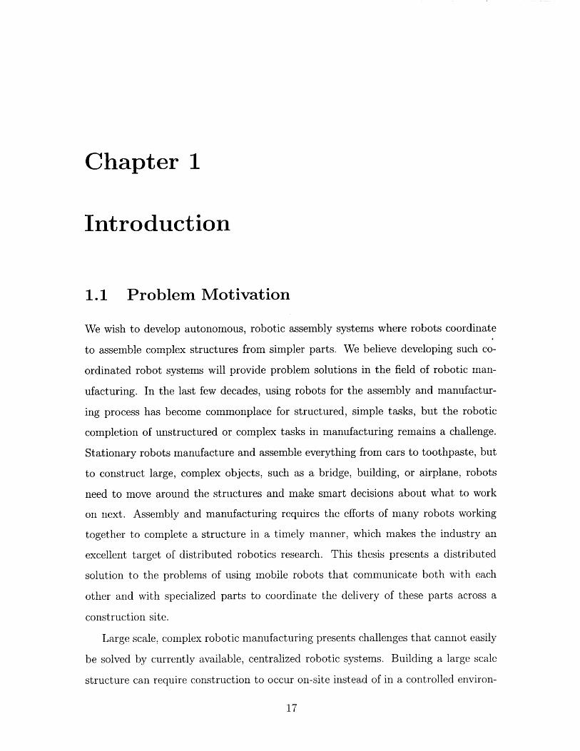
1-1 Figure of the main platform components: A robotic hardware platform,
Parts capable of communicating with the robot and giving the robot
information about their environment, and an algorithm that uses mul-
tiple robots coordinating to deliver parts to build a planned structure. 20
2-1 The prototype platform as modeled by previous research, where assem-
bly robots split the work to be completed between themselves. The
robots' overall goal is to complete the outlined structure, but each
robot focuses on the needs of the structure closest to it. . . . . . . . 25
2-2 The same system as time passes. The outlined structure is now par-
tially complete. Assembly robots split the work to left to be completed
between themselves, and parts brought by delivery robots go to the as-
sembly robot that still needs the most work done. . . . . . . . . . . 26
3-1 We model complex parts and materials used in construction with bars
and joints as basic building blocks. Such modular construction ma-
terials can form 3D structures. This 3D-rendered image of a cube is
constructed from 8 junctions, and 12 struts. Picture reproduced with
perm ission [3]. . . . . . . . . . . . . . . . . . . . . . . . . . . . . . . . 30

4-1 A timing diagram showing a sample set of communications in a task
loop of the system. Each column contains messages sent by either robot
R1, R2, or R3. The dotted line indicates the point at which robot R2
completes its period of listening for target robots and chooses the robot
with the highest demanding mass for parts heard at that point. . . . 41
4-2 The module interfaces provided information and functionality to the
high-level task planner, which also runs in its own thread. . . . . . . 42
4-3 The task planning event loop for the delivery robots. The main loop
pauses and loops back on itself at points where continuing requires
asynchronous communication from other robots. . . . . . . . . . . . 43
4-4 The task planning event loop for the assembly robots. The main loop
pauses and loops back on itself at points where continuing requires
asynchronous communication from other robots. At this point, assem-
bly robots only receive parts to be assembled at the proper location. 44
4-5 The arm finds parts by iteratively scanning smaller and smaller areas
for an IR signal being emitted from the part in question. A wider open
gripper widens the cone of view available to the sensor on the arm,
and narrowing the gripper shrinks the cone of view, allowing the arm
to pinpoint the part's location. . . . . . . . . . . . . . . . . . . . . . 45
4-6 Task loop for the navigation module with sensory input. . . . . . . . 47
5-1 Side view of robot hardware. . . . . . . . . . . . . . . . . . . . . . . . 52
5-2 Rotation and position freedom of the Crustcrawler arm. From a fixed
base, the arm allows for grasping an object on the ground in a half-arc
in front of it with a depth of about 20cm . . . . . . . . . . . . . . . . 53
5-3 The small IR communication modules on a PCB that can be embedded
in parts to create a smart environment for the robots to sense. Figure
reproduced with permission [3] . . . . . . . . . . . . . . . . . . . . . . 55
5-4 The laser-printed parts to be delivered: on the left, a red 'connector'
part and on the right, a blue 'truss' or 'strut' part. . . . . . . . . . . 55
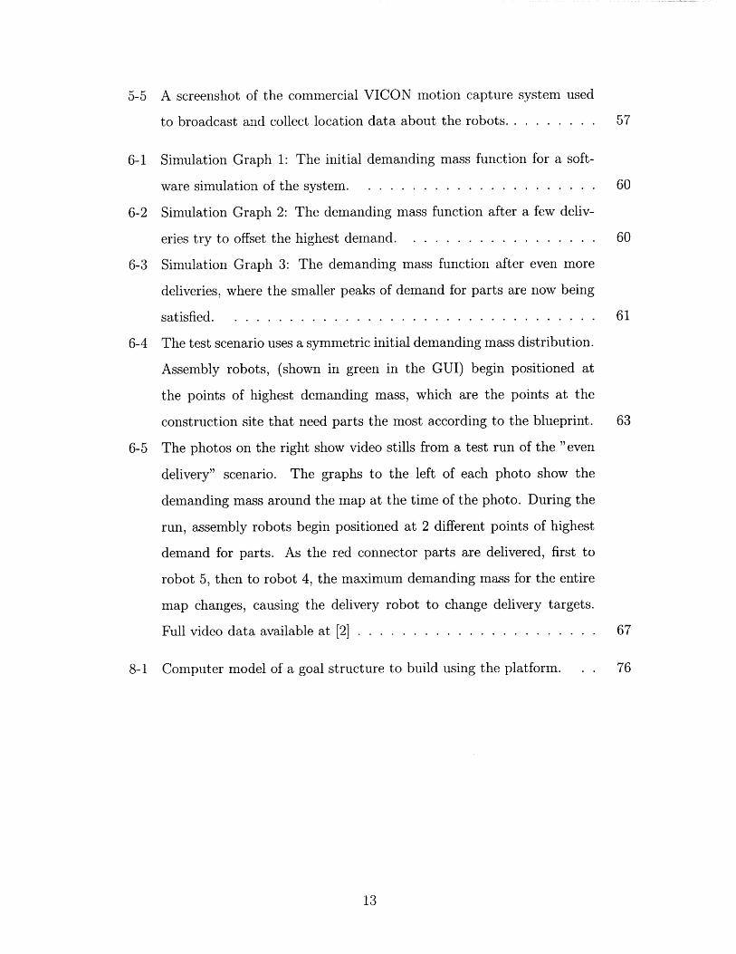
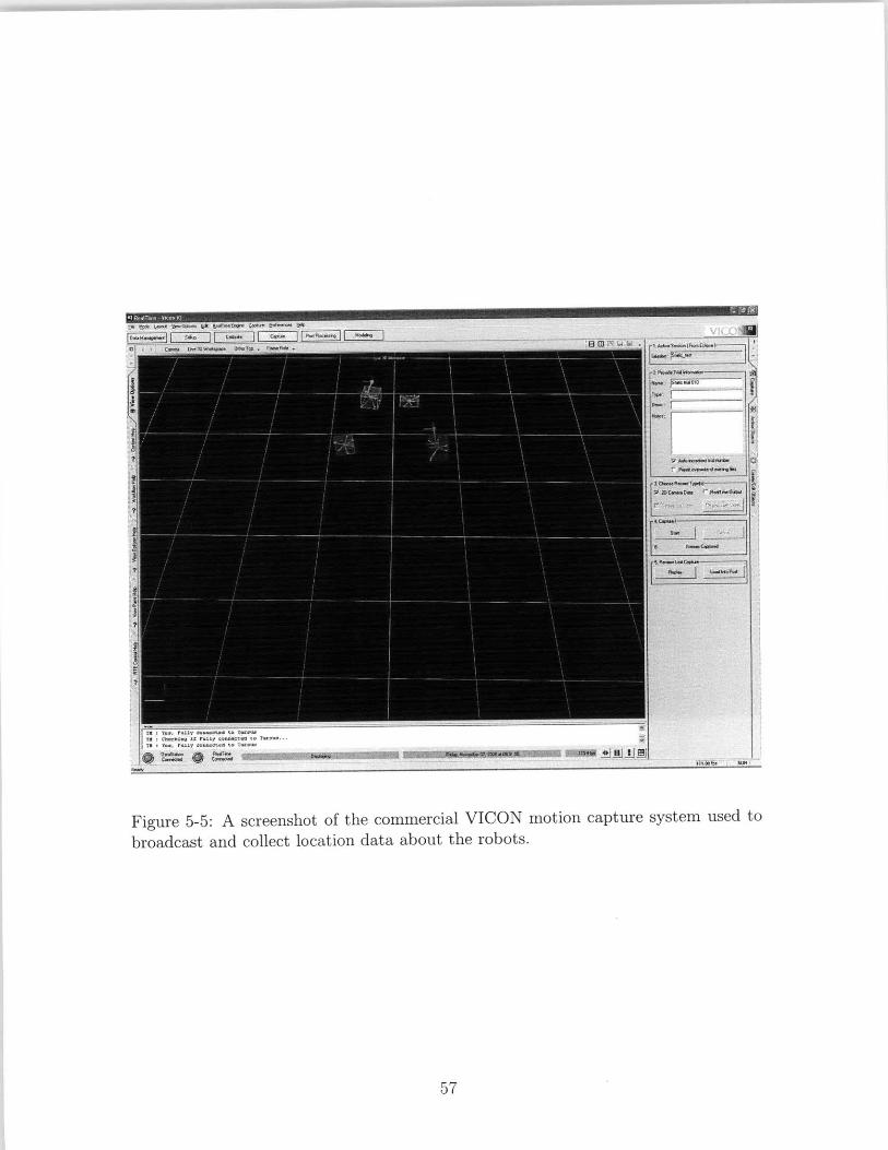
5-5 A screenshot of the commercial VICON motion capture system used
to broadcast and collect location data about the robots. . . . . . . . . 57
6-1 Simulation Graph 1: The initial demanding mass function for a soft-
ware simulation of the system. . . . . . . . . . . . . . . . . . . . . . 60
6-2 Simulation Graph 2: The demanding mass function after a few deliv-
eries try to offset the highest demand. . . . . . . . . . . . . . . . . . 60
6-3 Simulation Graph 3: The demanding mass function after even more
deliveries, where the smaller peaks of demand for parts are now being
satisfied . . . . . . . . . . . . . . . . . . . . . . . . . . . . . . . . . . 61
6-4 The test scenario uses a symmetric initial demanding mass distribution.
Assembly robots, (shown in green in the GUI) begin positioned at
the points of highest demanding mass, which are the points at the
construction site that need parts the most according to the blueprint. 63
6-5 The photos on the right show video stills from a test run of the "even
delivery" scenario. The graphs to the left of each photo show the
demanding mass around the map at the time of the photo. During the
run, assembly robots begin positioned at 2 different points of highest
demand for parts. As the red connector parts are delivered, first to
robot 5, then to robot 4, the maximum demanding mass for the entire
map changes, causing the delivery robot to change delivery targets.
Full video data available at [2] . . . . . . . . . . . . . . . . . . . . . . 67
8-1 Computer model of a goal structure to build using the platform. . . 76

14

List of Tables
A. 1 The unit cost of creating a single prototype robot . . . . . . . . . . . 79
A.2 Additional system costs . . . . . . . . . . . . . . . . . . . . . . . . . 80

16
Chapter 1
Introduction
1.1 Problem Motivation
We wish to develop autonomous, robotic assembly systems where robots coordinate
to assemble complex structures from simpler parts. We believe developing such co-
ordinated robot systems will provide problem solutions in the field of robotic man-
ufacturing. In the last few decades, using robots for the assembly and manufactur-
ing process has become commonplace for structured, simple tasks, but the robotic
completion of unstructured or complex tasks in manufacturing remains a challenge.
Stationary robots manufacture and assemble everything from cars to toothpaste, but
to construct large, complex objects, such as a bridge, building, or airplane, robots
need to move around the structures and make smart decisions about what to work
on next. Assembly and manufacturing requires the efforts of many robots working
together to complete a structure in a timely manner, which makes the industry an
excellent target of distributed robotics research. This thesis presents a distributed
solution to the problems of using mobile robots that communicate both with each
other and with specialized parts to coordinate the delivery of these parts across a
construction site.
Large scale, complex robotic manufacturing presents challenges that cannot easily
be solved by currently available, centralized robotic systems. Building a large scale
structure can require construction to occur on-site instead of in a controlled environ-

ment such as a factory. Mobile robots cannot rely on the same precision of position
that a static robot, such as an arm on an assembly line, can provide. Robots move
around and manipulate an environment that is guaranteed to change with a struc-
ture's building progress. Further, large scale projects require coordination of large
amounts of different types of resources spread across the entire project. Resources,
including both the materials and the labor of a structure, must be allocated efficiently.
Distributed, mobile robotic systems have characteristics highly desirable for large
scale building projects, but most current work in distributed robotics involves military
and surveillance applications where robots seek mostly to observe the environment
rather than manipulate it. Without central control, a distributed system does not
have as many size limitations, and individual robots are easily replaced as they break
or wear down without causing a holdup of the whole system. Our delivery platform
seeks to take advantage of these characteristics, and expand them beyond systems
that observe their environment to systems that change their environment by adding
materials to it and coordinate to keep track of these changes.
We developed a distributed mobile robot platform in hardware and in software to
deliver parts around a model construction site. We used a mobile robot base consisting
of an iRobot iCreate, a robotic manipulation platform created from a CrustCrawler
robotic arm, a part-sensing system designed using infrared communication, and a
Dell netbook to control the robot. We developed parts that also use infrared commu-
nication to alert the robots to their presence. We implemented a distributed control
algorithm designed to make specialized delivery robots deliver parts around the con-
struction site to dispersed assembly robots in a fair manner based on which robots
still needed the most parts. The robots carry out this distributed algorithm using a
communication protocol we designed that is sent out over a wireless network. The
assembly robots use the algorithm and communication received from other robots to
determine which parts they need to build a structure, and the delivery robots use the
same algorithm and communication to deliver the parts to assembly robots around
the construction site fairly.

1.2 Contributions
Given the challenges associated with large scale manipulation of an environment by
robots, but also given the expense in time and money associated with creating an
army of robots, this thesis work centers on the design and development of a set of
inexpensive robots still capable of moving, manipulating parts, and demonstrating the
complex control and coordination that would be required to assemble a large-scale
structure. The platform demonstrates the ability of multiple robots to coordinate
with each other to deliver parts. The robots can localize, sense parts, and pick up
and put down parts, and move parts around the construction site based on the current
needs of the structure being assembled. The robots in the platform can communicate
with any robots in their immediate vicinity and give each other their global locations
and needs for construction parts. The robots can also communicate with the parts
that they pick up, identifying the type of resource of each part and identifying where
around the site the part should go using intelligence conveyed by the parts. The
distributed system demonstrates limited fault tolerance; the failure or addition of a
single robot does not stop progress on the delivery of parts around the site. This
thesis explores the design of the platform in a cost-efficient way that will allow the
platform to be used for continuing research into efficient delivery of parts and also
into constructing structures with delivered parts.
This Masters in Engineering Thesis has made the following contributions toward
our goal of developing autonomous robot assembly systems:
1) development of a robot assembly system capable of distributed assembly of
parts
2) development and implementation of collision-free multi-robot navigation
3) development and implementation of communication layers for robot interactions
4) development and implementation of part delivery algorithm
5) development and implementation of part identification and grasping algorithm
6) extensive testing of the distributed part delivery system
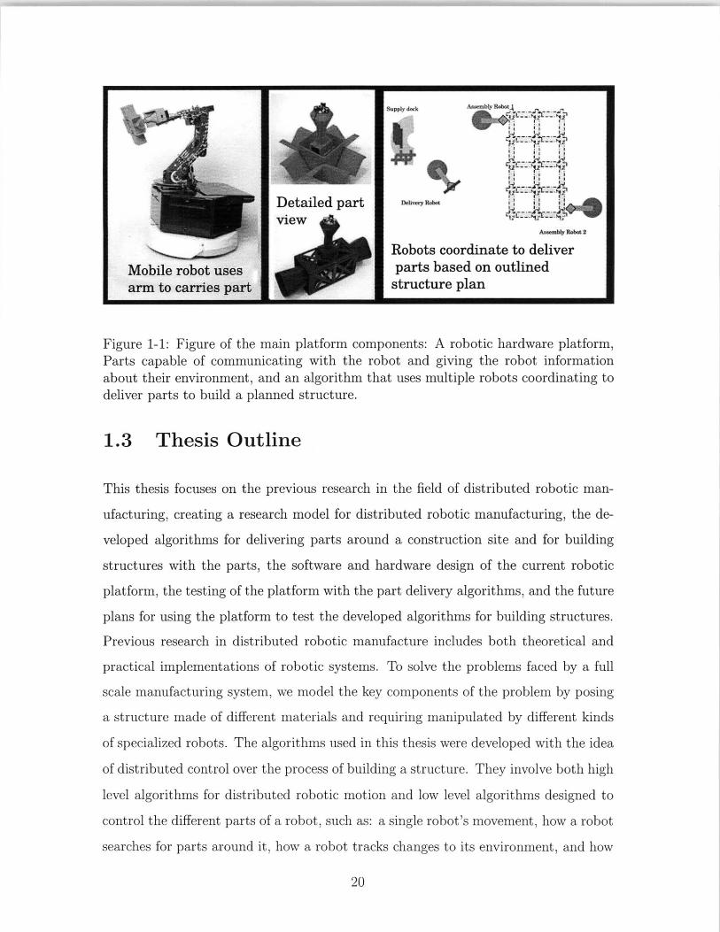
Figure 1-1: Figure of the main platform components: A robotic hardware platform,Parts capable of communicating with the robot and giving the robot informationabout their environment, and an algorithm that uses multiple robots coordinating todeliver parts to build a planned structure.
1.3 Thesis Outline
This thesis focuses on the previous research in the field of distributed robotic man-
ufacturing, creating a research model for distributed robotic manufacturing, the de-
veloped algorithms for delivering parts around a construction site and for building
structures with the parts, the software and hardware design of the current robotic
platform, the testing of the platform with the part delivery algorithms, and the future
plans for using the platform to test the developed algorithms for building structures.
Previous research in distributed robotic manufacture includes both theoretical and
practical implementations of robotic systems. To solve the problems faced by a full
scale manufacturing system, we model the key components of the problem by posing
a structure made of different materials and requiring manipulated by different kinds
of specialized robots. The algorithms used in this thesis were developed with the idea
of distributed control over the process of building a structure. They involve both high
level algorithms for distributed robotic motion and low level algorithms designed to
control the different parts of a robot, such as: a single robot's movement, how a robot
searches for parts around it, how a robot tracks changes to its environment, and how

parts can contribute to the environment knowledge of the robots that pick them up.
The robots' hardware design complements these algorithms and allows for a complete
but relatively inexpensive experiment setup. The evaluation of how the robots use
this design to deliver parts around the construction site takes into account cost, time
required to complete deliveries, communication complexity, algorithmic correctness,
and other metrics. Finally, the evaluated design inspires discussion on the platform's
future usefulness implementing the previously discussed algorithms for assembling a
structure at the construction site in parallel with the already implemented methods
of delivering parts around the site.

22

Chapter 2
Related Work in Distributed
Robotic Construction
The robotic platform discussed in this thesis builds on a large body of work from
the fields of robotic manufacturing, decentralized robot control, and instrumented
robotic tools. Relevant theoretical work in the field of distributed robotics includes
the development of load-balancing algorithms for groups of robots communicating
over a wireless network, particularly coverage control algorithms that try to ensure
communication and sensing over as much of a space as possible. Practical distributed
robotic systems currently emphasize military applications such as surveillance and
guided targeting, but a growing industrial setting for distributed robotics provides
some examples of distributed robotic systems that manipulate their environment.
2.1 A Distributed Control Algorithm for Assem-
bly and Manufacture
Various theoretical controllers have been developed [1] for mobile coverage control,
that is, spreading out a distributed robot system across terrain using communication
and location information to cooperatively explore a space. These controllers base,
designed originally as sensing networks, base their work on cooperative communi-

cation, and they have applications as a system of robots that actively change their
environment in addition to sensing it.
Completed research on the concept of "equal mass partitioning" forms the dis-
tributed control algorithm used by the robots in this paper's robot assembly system.
Equal-mass partitioning as described by [6] optimizes where the delivery robots choose
to deliver parts to assembly robots. The algorithm divides up the construction of the
object into geographic spaces (using Voronoi partitions) containing equal amounts of
work remaining, similar to older distributed algorithms for sensing and surveillance
coverage. However, equal-mass partitioning adapts to the system changing its own
environment on purpose. If work on one section proceeds more quickly, the algorithm
will balance this out by reallocating resources to sections with more work left undone,
maximizing parallelization of the work. Equal mass partitioning also specifies that
delivery robots choose where to deliver based on a specific function of work left to do,
known as demanding mass. This thesis implements the proposed idea of demanding
mass explored in [6]. The thesis allows the delivery robots to place parts at the op-
timum place provided by this previous work as shown in Figure 2-1, and eventually
will allow assembly robots to construct structures based on the algorithm as seen in
Figure 2-2.
Much theoretical research has been completed in the area of robot assembly sys-
tems, but few practical implementations exist. The relatively few practical systems
in place compared to theoretical controllers and research has been noticed, with ef-
forts made to document the difference between theoretical and practical distributed
robotic systems [81.Current practical research involving robotic coordination and communication fo-
cuses on using local data to achieve a goal global effect. Yun and Rus [5] describe the
implementation of a 3D system of robots that climb trusses. Each robot knows only
its own goal: to move to one of many desirable goal locations until all goal locations
are occupied by a robot. Their distributed algorithm allows the robots to spread
themselves around using only local location information about nearby robots.
Autonomous, communicating robots have also been used in an attempt to create
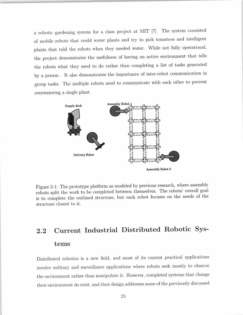
a robotic gardening system for a class project at MIT [7]. The system consisted
of mobile robots that could water plants and try to pick tomatoes and intelligent
plants that told the robots when they needed water. While not fully operational,
the project demonstrates the usefulness of having an active environment that tells
the robots what they need to do rather than completing a list of tasks generated
by a person . It also demonstrates the importance of inter-robot communication in
group tasks. The multiple robots need to communicate with each other to prevent
overwatering a single plant.
Supply dock Assembly Robot 1
2 5IJ
Delivery Robot
Assembly Robot 2
Figure 2-1: The prototype platform as modeled by previous research, where assemblyrobots split the work to be completed between themselves. The robots' overall goalis to complete the outlined structure, but each robot focuses on the needs of thestructure closest to it.
2.2 Current Industrial Distributed Robotic Sys-
tems
Distributed robotics is a new field, and most of its current practical applications
involve military and surveillance applications where robots seek mostly to observe
the environment rather than manipulate it. However, completed systems that change
their environment do exist, and their design addresses some of the previously discussed

Delivery Robot Assembly,- Robot 2
Supply dock Assembly Robot 1
Figure 2-2: The same system as time passes. The outlined structure is now partiallycomplete. Assembly robots split the work to left to be completed between themselves,and parts brought by delivery robots go to the assembly robot that still needs themost work done.
problems with scalability. The best examples of the scalability of mobile robots that
manipulate the environment come from agriculture and warehouse storage.
Harvest Automation Inc. [4] has created a robot called the Gardener that has a
single job: move large numbers of potted plants into an evenly shaped grid. Each
Gardener robot uses local sensing data to keep plant pots a certain distance apart, and
multiple Gardener robots can work in a single large greenhouse, rearranging potted
plants all day long.
The second commercial large-scale implementation of a distributed robotics sys-
tem involves using robots for inventory management. Kiva Systems has implemented
a distributed robotics system in which large numbers of small orange robots keep track
of the location of all the inventory in a warehouse and move around the warehouse,
fetching mobile shelves of inventory on request [9].
While both these systems use large numbers of small robots, neither system con-
tains the level of coordination required for distributed robotic manufacturing. The
robots coordinate at the minimum require level for mobile robots: they merely stay
out of each others' way while shaping their environment. In addition, the Kiva System
requires a very specialized, stable environment in which to work: a custom designed
warehouse where robots run on tracks as they move orders around. However, both

systems work well using large numbers of small, relatively cheap robots, an important
consideration in system development that the system described in this paper takes
into account.

28

Chapter 3
Modeling a Distributed
Manufacturing System
Our robot assembly platform consists of two types of robots: part delivery and part
assembly robots. These robots must have the ability to locate, identify, grasp and
manipulate the parts needed to form an assembled structure. Traditionally, robots
use computer vision algorithms for object recognition and grasping, but current com-
puter vision algorithms perform poorly in cluttered environments. The goal assembly
of our system requires many parts stacked right next to each other and possibly in-
terleaved. In such a cluttered situation, occlusions, lighting, and field of view bring
significant uncertainty in the object recognition problem. Therefore, we explore the
use of communication and coordination instead of computer vision for part location,
recognition, and grasping. Each part in the system is augmented by a 2-way com-
munication system. A single part can send infrared beacons to help a robot locate
it, and it can send its own part description to help the robot identify it. We call the
parts enhanced with the ability to communicate with robots smart parts.
In this chapter we describe our modeling and assumptions regarding the robots,
the smart parts, and their interaction. We explore the requirements of building a
structure from the perspective of a distributed group of robots coordinating with
each other. We list the main concerns of building a structure: the materials required
for building the structure, transportation of the materials around a construction site,

Figure 3-1: We model complex parts and materials used in construction with barsand joints as basic building blocks. Such modular construction materials can form3D structures. This 3D-rendered image of a cube is constructed from 8 junctions,and 12 struts. Picture reproduced with permission [33.
the specialized tools and labor required to build the structure, and the planning
involved in using these resources. We interpret these concerns as general challenges
that must be met by a distributed robotic system and propose a system that models
each of these concerns using smart parts.
3.1 Modeling Building Components with Smart
Parts
Building a general structure requires the acquiring and joining together of different
structural components. A platform designed to build a complex structure starts
with an underlying model that contains more than a single type of component. Our
model uses two types of components: joint structures to be placed at corners and
intersections, and bar shaped truss structures that can be rotated between joint

structures as in Figure 3-1. We chose to use these two types of components because
they generalize well into building larger structures.
Assembling a structure out of different types of components requires the ability to
tell the components apart and the knowledge of which component goes where. In our
platform, instead of placing the total burden of this intelligence on the robots only,
we impart much of this knowledge to the components themselves. The robots of this
system, in order to implement a controller that calls for different kinds of parts, must
be able to differentiate between parts. Rather than use cameras or other sensors on
the robot to do this, the system implemented in this paper uses active parts; the parts
to be assembled each contain powered, custom designed chips with IR transmitters
[3]. These chips contain the knowledge of their type, which they communicate to any
robot that asks for it, solving the problem of how robotic manipulators will sense
and distinguish components. The memory of the components can store information
given to it by a robot, meaning that robots can tell parts where they are and will be
located.
The chips designed to hold this information are actively involved in their own de-
livery and use in the construction process, and their participation makes traditionally
difficult robot behaviors simpler. The components can report, store, and modify in-
formation about the structure they are being used to build. They can also broadcast
this information around them, making it possible for robots to find the parts that are
asking to be picked up and assembled by homing in on a part's IR beacon. Previous
research has demonstrated the chips' high rate of effectiveness and flexibility when
used to identify objects compared to using recognition techniques like computer vi-
sion, which involves cameras, lighting conditions, image training sets, etc. The chips
embody the idea of using a smart, distributed environment for construction instead
of a smart robot that must make all the decisions. Having chips in parts further
distributes the knowledge of how to build the structure, so simple robots must do less
work in identifying the correct parts to pick up, a crucial need for assembly robots
looking to distinguish between similar parts.

3.2 Modeling Tools and Part Delivery
Our model deals with the load-balancing problem of having multiple delivery robots
deliver components to multiple assembly robots around the construction site using
communication. Our model assumes at least one robot is available to deliver each
necessary type of component, but that more than one delivery robot for each type of
component will usually be available. First, we model a structure with a blueprint that
has the locations of all the components in their final positions and the starting source
location of all the components. Our robots keep track of which parts have been
delivered already using communication. We develop an algorithm to fairly deliver
components all over the blueprint as construction progresses on the structure, and we
base where the robots should deliver components based on which part of the structure
remain the least finished.
3.2.1 Specialized Delivery Robots
Structural components must be moved to their locations before they can be assembled,
and we model this need using specialized delivery robots. In our distributed platform,
multiple robots, each specialized to only deliver a certain component type, model
the delivery of different components around the construction site. One type of robot
delivers only truss-type parts, and another type of robot delivers only joint-type parts.
We make the assumption that delivery robots are specialized because it is possible
that building a structure requires different capabilities from robots delivering items
that range from screws to large steel beams.
3.2.2 Delivery without Completely Connected Robot Com-
munication
We do not model the robots at our construction site as having complete network
visibility; every robot at the site does not need to be in contact with every other
robot. This non-assumption impacts how our platform solves the delivery problem.

Since the sheer number of robots on a large scale project, terrain difficulties, or
communication errors may prevent all the robots from contacting each other, we
model all of these problems by assuming only that each robot can see the robots
closest to it geographically. Using this realistic model, our algorithms for delivering
parts fairly rely partly on randomness to compensate for such errors.
3.3 Modeling the Assembly of the Structure
Although our platform does not implement assembling a structure, we modeled the
situation anyway with plans for using the platform for assembling a structure in
the future. We designed our different part be joinable by our robots' manipulation
platform, modeling a variety of setups in which specialized robots assemble parts. We
made the assumption that multiple assembly robots would try to work in parallel,
speeding up the process of assembling the structure. Finally, we made the same
assumption about communication connectivity that we made for the delivery robots:
assembly robots may only be able to communicate messages to their near neighbors.
3.3.1 Assembly Robot Load Balancing
We model the assembly robots' tasks as attempts at maximizing parallelization while
building a structure so as to finish the structure as quickly as possible using all avail-
able assembly robots. The assembly robots divide up the work among themselves
as evenly as possible according to an algorithm that we developed, and as time pro-
gresses they re-divide work using that algorithm and communication from the nearest
robotic neighbors [6].
3.3.2 Assembly Robot Part Manipulation
The role of an assembly robot in our system is to take both types of available com-
ponents and combine them according to the blueprint. For this reason, our assembly
robots are equipped to manipulate both the 'joint' and the 'truss' types of components

present in our system. This models the role of an assembly robot on a manufactur-
ing floor- such a robot might be equipped with a tool that attaches one part of the
structure to a different part once both have been delivered. Our current model does
not specialize assembly robots because we only need to combine two types of com-
ponents, but our model can be extended to use specialized assembly robots to do
different tasks. Assembly robots may play different roles in building a structure, but
their interaction with available parts and delivery robots remains the same, dictated
by the need for components.
3.4 Proposed Solution to the Model Problem
Using our model criteria, we developed a hardware and software platform consisting
of 2 types of specialized delivery robots, general assembly robots and 2 types of
intelligent parts that communicate with the robots. We place the intelligent parts
at a supply station at a known location. Specialized delivery robots visit the supply
station and use their ability to communicate with the parts to find the correct type
of part and pick it up. The delivery robot communicates with all assembly robots
within hearing range in order to determine where the part should be delivered, and
then the delivery robot delivers the part. Assembly robots respond to this delivery
by readjusting their own need for parts and communicating this change to their
neighbors, propagating information, in turn changing where delivery robots deliver
parts. Assembly robots then manipulate the delivered parts in order to build the
structure. The hardware and software developed for the platform currently solve the
proposed delivery problem. The developed robotic and part hardware will be used to
assemble structures in concert with assembly robot coordination software still under
development.
Chapter 4
System Design and Control
4.1 Inter-Robot Controller
4.1.1 Overall Algorithm
The top-level goal of the system, to use mobile robots to deliver parts efficiently
around a construction site to build a structure, requires mobile delivery and assembly
robots. Algorithms 1,2, and 3 describe the top level control loops for coordinating
part delivery. From a centralized point of view, the steps of the algorithm consist
of running all delivery robots and assembly robots at the same time as directed in
Algorithm 1, communicating intermittently to keep themselves synchronized. The
assembly robots calculate the parts required to build the entire structure and divide
the structure among themselves into connected geographical regions, each requiring
of equal amounts of work. Each assembly robot then moves within its designated
space to the point with the highest need for parts and begins broadcasting a request
for parts so it may begin building. Yun and Rus [6] describe the division of the work
required to build a structure using Voronoi partitions. They show that each assembly
robot should choose where to move inside its own partition, and a dynamic controller
that changes the distribution of work (and the geographical size and location of each
robot's work space) based on how much work is already completed will converge and
allow the structure to be built as in Algorithm 2.

For the evaluation of the delivery system, we assume that assembly robots have
already reached their desired locations and ask for parts from delivery robots accord-
ing to the need for the parts. We quantify the need for parts at a given location as
#(x, y), the demanding mass at a given (x,y) position. The delivery robots use the
way assembly robots ask for parts to determine which assembly robots need parts the
most, and deliver to the area accordingly as shown in Algorithm 3.
Algorithm 1 High level, Centralized Perspective of Part Delivery1: Place the assembly robots around construction site space Q2: repeat3: Delivery robots pick up parts from supply source and carry parts to individual
assembly robots (Section 4.2.1)4: Assembly robots update their need for parts and ask for more parts (Section
4.2.2)5: until all necessary parts for structure delivered
Algorithm 2 High Level Algorithm: Distributed Delivery Robot Perspective of PartDelivery
1: repeat2: Move to the supply source.3: Pick up a part of the correct type (Section 4.2.3)4: Move to random place in Q, the construction site space.5: Listen to broadcasts from all nearby robots6: Deliver to nearby assembly robot with highest #.7: until All necessary parts have been delivered.
Algorithm 3 High Level Algorithm: Distributed Assembly Robot Perspective ofPart Delivery
1: repeat2: Determine Q', the part of construction space Q assigned to me (Section 4.2.2)3: Calculate #, the highest need for parts anywhere inside Q' (Section 4.1.2)4: repeat5: Broadcast # to all nearby robots6: until Delivery robot responds by delivering a part to me (Section 4.1.3)7: until All necessary parts have been delivered.

4.1.2 Construction Blueprint
Having a control algorithm on a construction site ensures that work progresses evenly,
maximizing parallelization [6]. Delivery robots must deliver evenly around the con-
struction site, or some assembly robots will site idle as they wait for more parts,
while other assembly robots will continuously assemble parts and have extra parts ly-
ing around them in their way. The control algorithm here accomplishes even progress
by using the assembly robots' work division to determine who needs parts to build
the most at any given time using a blueprint: an overall plan for where parts should
be delivered that each individual robot maintains an internal copy of with the most
updated information.
The distributed control algorithm tries to ensure generally equal building progress
towards the completion of a structure. The algorithm pulls the progress of the whole
structure from the blueprint module, available to each robot. All of the robots on
the construction site work from a local copy of the overall blueprint for construction,
which they update with the information they receive through communication with
other robots. At the beginning of construction, the robots tasked with assembling the
structure should spread out and stand at the locations where parts are most required.
A blueprint may define any function for determining where parts are needed most as
long as the function can supply a gradient telling assembly robots where to move to
do the most amount of work [6]. As construction proceeds, the already assembled
parts on the blueprint change the location of the highest need for parts. The high
level planner for both the delivery robots and the construction robots both receive
the latest information about parts from the communication module and update the
blueprint with this information.
Every planned structure requires its own custom blueprint. The blueprint contains
a collection of all the parts needed for the goal structure and which parts depend
on other parts being delivered first. Parts that cannot be used yet because of a
dependency are not included in a calculation of the needed parts at a given location.
The simplest blueprint constructed for this system consists of 2 piles of parts, each

pile containing both "truss" and "connector" type parts, and none of the parts are
dependent on each other. More complicated blueprints are necessary for cube or
bridge-shaped structures. The final ingredient for a distributed blueprint is a function
for calculating the need for parts at a given location on the map, referred to here as
a demanding mass function, or as #.The highest demanding mass as a function of the robot's position is intuitively
calculated by adding up the number of parts still required near any specific point in
the construction site and penalizing positions far away from parts as a function of
distance. Our algorithm uses the following formula based on a Gaussian probability
distribution function with tunable parameter o-:
(distancei /maxDistance)2
#(position) = L Ai( e- 20 )
The formula is used by an assembly robot to calculate the demand for parts at a
given location, where n is the number of parts still needed and Ai = 1 if part i does
not depend on any parts not on the board yet, 0 otherwise. The indicator function
A incorporates the idea of part dependency into the structure; for parallelization,
common sense dictates that parts for the top part of 3D tower, for example, should
not be delivered to sit around when the bottom part of the tower must be delivered
first anyway.
The scaled distance parameter distance /maxDistance ranges from 0, where robot
i is on top of the part, to 1, where robot i is on the opposite corner of the construction
site, and corresponds to the distance from the mean in a normal Gaussian distribution.
The parameter o can be tuned based on the scale and size of the construction site
and parts, depending on how fine grained the mass function needs to be to correctly
direct assembly robots to the areas of the construction site that need parts.
The demanding mass function used in this system is based on a Gaussian distri-
bution because such a distribution can be conveniently differentiated to determine
in which direction an assembly robot should go to assemble parts. In addition, each
parts' contribution to the total demanding mass sums always to 1 regardless of where
the part is placed, meaning that outlier parts located far away do not skew demand

too much in a far off spot, as would be the case if demanding mass was based on a
linear sum or difference of distances. The formula works well with a variance inversely
proportional to the number of available assembly robots because more available as-
sembly robots means that the site is split into smaller, more specialized partitions
whose demanding masses should be less dependent on each other. These properties
allow each assembly robot to calculate their own position-based demanding mass that
accurately reflects the needs for parts at a construction site as a single number that
can be compared to the needs of other robots, and also broadcast to other robots
such that they can update their own knowledge of a construction site.
4.1.3 Inter-Robot Communication
The communication modules of the robots broadcast general queries for parts and
where to deliver them. When delivering and accepting parts from specific robots, a
robot will still broadcast its message for all to hear, but it will address its message to
the target robot as a way of requesting acknowledgement. A handshake mechanism
of acknowledgements is required for either a delivery robot or an assembly robot to
proceed to the next stage of making or accepting a delivery.
The handshake mechanism consists of request messages, confirmation messages,
and rejection messages. It is based on the assumption that if, after a certain length
of time, no response is received, that the other robot has given up or broken. A "no
response" is treated the same way as a rejection message- the rejection message is just
a faster way of moving the system along. A rejection message is sent by an assembly
robot A to a delivery robot B if a delivery robot B tries to target a robot currently
being targeted by a different delivery robot C. This keeps all robots trying to lower
the overall demanding mass, but keeps all the delivery robots from waiting on the
same assembly robot at once.
To account for errors and lag, messages may be sent and acknowledged more
than once with no negative consequences. The example timing diagram Figure 4-1
demonstrates the exchange between Robot R2 and R3, where Robot R1 continues
to request delivery in the background on the same multicast channel. Robot R2's

delivery of part A changes R3's demanding mass. If this message exchange continued,
R2 would deliver to Ri because RI's demand for parts is now higher.
The multicast channel means that more information is shared about exchanges
to any other robots that happen to be nearby. RI's requests are still being received
and recorded by R2 for future reference. The most recent message, defined by the
logical timestamp of the message, is stored by R2's communication module. Logical
time designates the order in which messages are timestamped and set as opposed to
the order in which they may be received. In the same way, R1, if located closely
enough to R3, will listen when R2 broadcasts where it has placed the part down on
the ground and update its blueprint map accordingly. This information can then be
propagated to other robots that can hear RI's broadcast but not R3's broadcast.
4.2 Single Robot Control
The overall plan for delivering parts around a construction site using communication
between part manipulating robots relies on each robot having several internal modules
controlling many complex lower level robot behaviors such as obstacle avoidance,
part finding, mobility, location sensing, and transmitting messages. We designed the
architecture of the robot to implement these behaviors hierarchically to allow for
more complex behavior overall. Since multiple modules of the robot constantly take
in data from the environment and act with minimal direction from the high level task
planner, the control structure of each robot runs its sub-modules simultaneously. The
sub-modules, consisting of a navigation and localization module, a communications
module, and a part manipulation module, run independently of the highest-level task
planning module. All modules are implemented in their own Java threads. Each
module ran in its own thread and abstracted the necessary hardware away from the
planner as shown in figure 4-2.
This abstraction also allows different task planning modules to operate using the
same robot hardware. For the demonstration of our distributed controller, we de-
signed 2 task planning modules. First, we designed a robot whose task is to demand

Target Robot RI Delivering Robot R2 Target Robot R3i mDemanding mass = 6
Demanding mass = Demanding mass = 6
Demanding mass = 5
Intent to Deliver Part A to R3 Demanding mass = 6
Demanding mass = Intent to Deliver Part A to R3 Confirm R2 Intent
Intent to Deliver Part A to R3 onfirm R2 Intent
onfirm R2 Intent
Complete Delivery of Part A to R3
Demanding mass 5 Complete Delivery of Part A to Confirm R2 Delivery
Complete Delivery of Part A to Confirm R2 Delivery
Confirm R2 Delivery
Demanding mass =5
Demanding mass = 1
Logical Time t
Figure 4-1: A timing diagram showing a sample set of communications in a task loop
of the system. Each column contains messages sent by either robot R1, R2, or R3.
The dotted line indicates the point at which robot R2 completes its period of listening
for target robots and chooses the robot with the highest demanding mass for parts
heard at that point.
and acquire parts while sitting in the field of construction. Second, we designed a
robot whose task is to use our algorithm to decide which of a certain type of part
should be delivered to other robots and then deliver a part of that type. Both planners
use the same underlying hardware and lower level software.
4.2.1 Delivery Robot Task Planning
Each delivery robot runs a delivery task planner that uses a distributed algorithm to
decide which parts should be delivered to other robots. The delivery robot then deliv-
ers those parts. In order to accomplish this task, the planner pulls information from
the sensing and communications modules, continually updated in the background,

Internal Robot ArchitectureG Each module runs continuously in its own thread
Figure 4-2: The module interfaces provided information and functionality to thehigh-level task planner, which also runs in its own thread.
whenever necessary.
The first task of the planner is to acquire a specialized part from the supply source.
The robot scans through all the parts at the supply source for a part of correct type.
The planner moves to the supply source using the navigation module, docking with
the source so the robot's arm can search the supply source for the exact part that it
needs. The planner then asks the arm module to locate a part of the correct type.
Once a part is picked up by the arm, the planner tells the navigation module to move
the robot out of the way, opening the supply source for the next robot.
The distributed delivery algorithm works in a similar manner to well known cov-
erage control algorithms. It tries to ensure that all robots on the field of construction
receive parts to assemble together at an even rate overall [6]. To accomplish this goal,
the next step of the task planner moves the robot to a random place on the construc-

Assemblyi-~ Robots Not enough responses
Target robot robots respond
responds
Target
Confirm Move to nfagain with Drop Off Deliver dJconfi
Target Part Locat*on rbtRobotRobot
Target robot does Target robot doesnot respond not respond
Figure 4-3: The task planning event loop for the delivery robots. The main loop
pauses and loops back on itself at points where continuing requires asynchronous
communication from other robots.
tion site before asking which robots in the site need parts. If the planner skipped
this step, then at a large construction site where robots had limited broadcasting
distance, the task planner would only ever listen to the demands of assembly robots
closest to the supply depot and never satisfy the demands of robots out of broadcast
range regardless of the number of parts they required. Choosing a globally random
place from which to listen for local mass needs will distribute needed parts all over
the board at an even rate[6].
The delivery robot then stops to listen for the information provided by nearby
robots. In our implemented design, the robot waits for as long as 30 seconds. As-
sembly robots that need parts broadcast their needs every .5 seconds. As a result, in
evaluation, only 2 seconds were required to hear all the robots waiting in the field of
construction nearby. The delivery robot's task planner then chooses the robot among
those that it heard asking for parts that has the highest need for parts, also known as
'demanding mass.' The delivery robot notifies that assembly robot that it has been
targeted for delivery. If the targeted robot responds, then the delivery robot's task
planner moves itself to the target robot.
After nearing the target robot, the delivery robot puts down the payload at the

correct position and angle to be picked up by the assembly robot and notifies the
assembly robot of the delivery. Again, the planner waits for confirmation by the
other robot before moving on. Once it receives confirmation, the planner moves the
robot back to the supply source to start a new delivery loop.
4.2.2 Assembly Robot Task Planning
ecte Calculate Broadcast Listen for
eti Demanding Demanding OfferLoaton mass Mass for Part
Delivery robot
Start No response offers part
Attac Broacastdelivered Accept
Relocate Delivered part -4 confirmation DeleryofqMTo Structure / of delivery Roboter
Part not delivered yet
Part of Delivery Algorithm
- - - Future Assembly Algorithm
Figure 4-4: The task planning event loop for the assembly robots. The main looppauses and loops back on itself at points where continuing requires asynchronouscommunication from other robots. At this point, assembly robots only receive parts
to be assembled at the proper location.
The planner of the assembly robots demanding the parts for construction, has
a simple event loop in this system that forms the foundation for future work with
robots that put together parts that have been given to them. While further research
will involve using the assembly robot's arm to assemble structures, the first iteration
system goal of these robots is simple: each assembly robot should be located at
the site position with the highest need of their construction skills and wait there to
accept parts to be delivered. Their event loop consists of broadcasting what they
need around them and engaging in communication with delivery robots as explained
in Algorithm 3.

4.2.3 Part Manipulation
Creating a system of robots designed to deliver parts to a construction site requires
robots to manipulate parts using attached arms. The arm module of the robot must
manipulate parts using three different tasks: the arm must use its sensors to find the
correct parts to pick up, pick up the parts, and release them at the correct position.
Figure 4-5: The arm finds parts by iteratively scanning smaller and smaller areas foran IR signal being emitted from the part in question. A wider open gripper widensthe cone of view available to the sensor on the arm, and narrowing the gripper shrinksthe cone of view, allowing the arm to pinpoint the part's location.
Once a robot is docked at the supply station, or parked near enough to a part that
it needs to pick up, the high level task planner uses the arm module to find the part.
The IR sensor attached to the inside of the arm's gripper has only on-off control:
there is no way for the sensor to tell how close or far away a part even after it has
been detected. Instead, the sensor is narrowed by physically limiting the sensor's field
of construction of view into a small cone as shown in Figure 4-5. Narrowing down
the possible locations of the part allows the arm to fine tune its resolution enough
pick it up.
First, the arm points the sensor directly at the ground to avoid detecting any
parts that are out of its reach. Then, the arm compensates for the lack of distance
measurements in the sensor by progressively scanning smaller and smaller areas once
a part is detected. The first pass of an area requires scanning by moving the arm in
a 180 degree half circle around the front of the robot. Once the general area of the
part has been discovered, the arm narrows the sensor's cone of view until it no longer

sees the part, and rescans the small area until it finds the part again. This process
continues until the arm has been moved close enough to the part to grip the top of
it and pick it up. The arm confirms pickup by receiving a response from the part's
IR chip while the arm's sensor is not pointed at the ground, and the arm reports its
success to the high level planner.
We chose to use this iterative scanning motion to compensate for limitations in
the arm's hardware. The arm has no feedback attached to its servos, and no location
data about the arm's end effector. This lack of feedback makes typical robotic arm
motion planners that use speed or position-controlled inverse kinematics in the xyz-
space difficult without adding more complex sensors to arm. In addition, the parts
in the supply depot do not have a fixed xyz position. Since position-based control
cannot be used unless the arm has a destination position, and the part sensors do
not provide distances from parts, we elected to calibrate the arm and then move it
through several predefined positions to find any parts in its reach. The resulting
simple arc motions of the arm, combined with the IR sensor located at the base of
the gripper at the end of the arm, are sufficient to find and pick up any part within
the arm's reach, shown in the physical system as the blue "Supplies" area in Figure
4-5.
4.2.4 Localization and Navigation
The robot uses the incoming position data information to plan a path to the goal. The
xBee receiver attached to each robot processes received packets as fast as possible,
and the motion controller used by the robot requires accurate position data at a
rate of 2Hz. The VICON motion capture system used for localization broadcasts the
positions of all the robots on the field at 10Hz, providing extra information to correct
any errors in packets received by the robot. The robot's motion planner divides the
construction site into a grid of small square nodes measuring 10cm/side that share
8-way connectivity with their neighbors, removing from the graph any node with an
obstacle such as another robot or a part. The planner uses the A* search algorithm
to find the shortest path to the destination location, or to the closest destination

Figure 4-6: Task loop for the navigation module with sensory input.
location that is part of the graph. The graph, stored in a synchronous variable, is
updated with the new information about parts dropped off in the field by the overall
task planner whenever the high-level planner receives the information. The algorithm
is re-run every loop (i.e every 2Hz) to account for position changes of all robots and
dropped off parts in the field.
Since this system provides each robot with millimeter accurate data on the position
and orientation of all the robots around the construction site, the engineering prob-
lems associated with navigating around the site mostly concern controlling hardware
that does not provide the same precision of motion by compensating with software
design. The motion controller uses clipped proportional control to approach the tar-
get destination, slowing down as it approaches the goal. However, the forward speed
of the robot's hardware has a minimum speed insufficient to allow the robot to coast
to an exact stop. Once the robot is within a few centimeters of its goal location,
the robot pauses. To achieve a more accurate location, the robot turns forward and
backward very slowly to maneuver into position. This maneuvering allows the center
of the robot to get within 2 centimeters of the desired goal position, close enough
that movements of the robot's arm can compensate for the body position error when

trying to manipulate parts.
4.2.5 Communication
The communication module of the robot provides the latest system state to the task
planner. The robot's communication module runs constantly, so the most complete
information whenever the high level planner requests it. The module maintains the
latest state of every other robot broadcasting in the robot's signal range. It holds on
to the most recent message received from each robot. It also broadcasts out its own
state on the same channel for other robots to hear.
The robot sends and receives packets from other robots over a UDP multicast
channel on the local network, implemented in this prototype with a singe WLAN
router. These packets contain the most recent data available from other robots,
including a logical timestamp so packets from the same robot can be ordered. Both
delivering and part-assembling robots timestamp their packets. Robots delivering
parts send packets containing a robot ID number, their current position, and their
current target robot. They also broadcast their current state, so a delivery robot can
ask a targeted assembly robot for acknowledgement. More generally, all robots also
broadcast whether or not they are currently carrying or dropping off a part, which
part type they are carrying, where they are carrying this payload, and the knowledge
of any other known placed parts.
The communication module keeps the most recent data from each robot it knows
about in order to provide it to the planner. The delivery task planner requires keeping
track of the most recent part requests (according to the packet timestamp) from all
assembly robots in the field of construction so the planner can make the decision
of where to go next. The communication module also keeps track of parts that
other robots have reported putting down on the field of construction already so the
robot knows to avoid them while navigating the environment. Finally, in an effort to
provide a "handshake" mechanism between two robots, the communication module
keeps track of parts expected an assembly robot, whether or not a delivery robot has
delivered them yet, and whether or not the target assembly robot has acknowledged
the delivery.
The communication system's recording of part movements acts as an additional
sensing system for an otherwise nearly blind robot. Any robot en route to elsewhere
listens to robots around it, and a robot records where parts are being placed, and
which robots are the targets, in order to update their internal blueprint of construction
progress. Since delivery robots deliver parts based on what other robots in the field
of construction demand, the dissemination of knowledge about where parts have been
delivered is crucial. Assembly robots need an accurate internal map of the already
built site in order to calculate their own demanding mass value or to decide if they
should actually be located somewhere else[6]. While this information could result in
enormous message sizes for near complete structures, this cost does take the place
of external sensing and computation that would be required by the robot anyway to
calculate the parts currently on the map, a requirement for determining the next step
in building a structure. Also, optimizations for not sending repeated information are
possible- for example, once a robot hears the part it broadcasted being rebroadcasted
by another robot after a certain later point in time, it can be assured of dissemination
and stop broadcasting itself.

50

Chapter 5
System Hardware
5.1 Robot Hardware
This chapter details the robot, smart part, localization and communication hardware
used to implement the coordinated delivery algorithms described in Chapter 4. Each
robot's hardware includes a mobile platform, an arm, a IR transmitter capable of
communicating with the smart parts, a netbook capable of wireless networking, and
several batteries to power the modules. Each 3D-printed smart part contains a custom
IR chip designed to talk to the robots and a battery to power the chip. The robots
localized using data from a motion capture system broadcast over a mesh network.
The overall goals for the hardware of the system were to build an inexpensive,
workable prototype capable of demonstrating robotic delivery and assembly of a struc-
ture. To avoid reinventing the wheel, we bought commercial hardware when possible.
Besides cost, the hardware design presented challenges in terms of weight and power.
Various components employed different power sources, and all of these components
and their power sources needed to be carried on a small chassis. These design con-
straints resulted in a small mobile robot capable of running for a few hours at a time,
communicating with other robots in the vicinity, and using an arm to find, pick up,
and transport a 1-kilogram part.
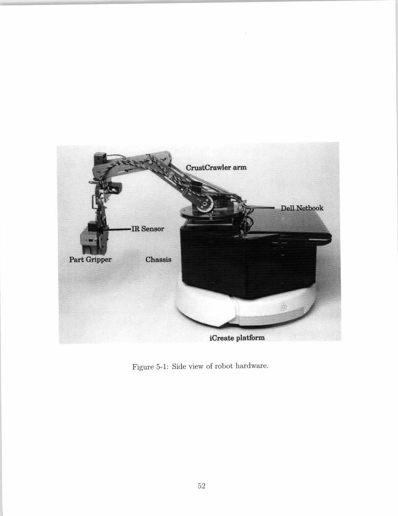
iCreate platform
Figure 5-1: Side view of robot hardware.
52

Figure 5-2: Rotation and position freedom of the Crustcrawler arm. From a fixedbase, the arm allows for grasping an object on the ground in a half-arc in front of itwith a depth of about 20cm.
5.1.1 Base
The main body of the robot consists of the iRobot iCreate mobile robot platform, a
commercially available robotic arm, and a custom chassis, made from laser-cut delrin
and designed to fit the two together as shown in figure 5-1. The mobile body of the
robot is an iRobot iCreate platform, powered by a 14 volt battery that will last for
several hours.
Both the iCreate base and arm are cost-efficient, but present a few challenges
that we overcome using more expensive sensors. The iCreate base's internal odome-
try is not accurate enough to use position-based navigation control. We were able to

improve the base odometry slightly by adding an additional caster wheel to the bot-
tom of the robot for smoother motion. In order to achieve the localization accuracy
necessary for placing parts in the system, all position control data comes from the
external motion capture system mentioned in the Localization section. The arm joint
motors have no feedback of any kind. Feedback for the arm comes completely from
custom-designed IR sensors located at the end effector of the arm. These sensors and
the additional communication module designed to spread knowledge from the sensors
to all robots are discussed in the next chapter.
5.1.2 Arm Manipulation
The arm and the robot base are controlled from the notebook using an USB-to-Serial
connection. The netbook controls the arm with a servo board (model Lynxmotion
SSC-32) that provides PWM control to the servos in the arm. The arm itself is
the SG5-UT 4-degree-of-freedom arm from Crustcrawler robotics connected to the
SSC-32. The arm model uses 4 servo motors capable of rotating 180 degrees each,
to achieve 4 degrees of freedom. (Motion range shown in figure 5-2). These pieces
are connected together using a chassis made of laser-cut delrin that stores the servo
board, the batteries powering the arm, and all the robot's USB hardware-to-netbook
connector cables.
5.1.3 Sensing and Communicating with Parts
The robot system's part detecting and manipulating tools result from extensive de-
sign work replacing traditional passive sensing, like sonar, with active sensing, where
the environment can be as smart as the robots manipulating it. Previous work has
resulted in small, light, programmable IR communication chips designed to sent bytes
of data at close range [3]. These chips are placed in the parts such that a robot can
scan them before deciding whether or not to pick up the part. In addition, the robot
can transmit information to the part, such as assigning it an identity and location,
that a second robot could then read from it. In this system, chips are programmed

Figure 5-3: The small IR communication modules on a PCB that can be embeddedin parts to create a smart environment for the robots to sense. Figure reproducedwith permission [3]
Figure 5-4: The laser-printed parts to be delivered: on the left, a red 'connector' partand on the right, a blue 'truss' or 'strut' part.
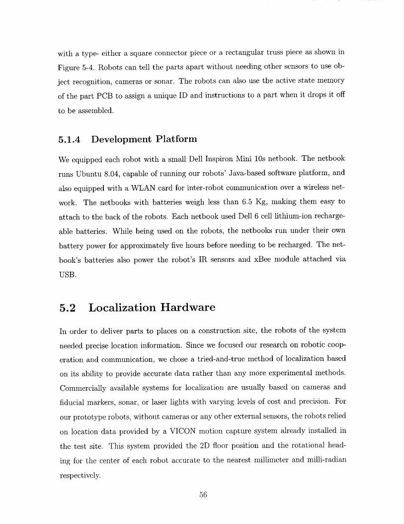
with a type- either a square connector piece or a rectangular truss piece as shown in
Figure 5-4. Robots can tell the parts apart without needing other sensors to use ob-
ject recognition, cameras or sonar. The robots can also use the active state memory
of the part PCB to assign a unique ID and instructions to a part when it drops it off
to be assembled.
5.1.4 Development Platform
We equipped each robot with a small Dell Inspiron Mini 10s netbook. The netbook
runs Ubuntu 8.04, capable of running our robots' Java-based software platform, and
also equipped with a WLAN card for inter-robot communication over a wireless net-
work. The netbooks with batteries weigh less than 6.5 Kg, making them easy to
attach to the back of the robots. Each netbook used Dell 6 cell lithium-ion recharge-
able batteries. While being used on the robots, the netbooks run under their own
battery power for approximately five hours before needing to be recharged. The net-
book's batteries also power the robot's IR sensors and xBee module attached via
USB.
5.2 Localization Hardware
In order to deliver parts to places on a construction site, the robots of the system
needed precise location information. Since we focused our research on robotic coop-
eration and communication, we chose a tried-and-true method of localization based
on its ability to provide accurate data rather than any more experimental methods.
Commercially available systems for localization are usually based on cameras and
fiducial markers, sonar, or laser lights with varying levels of cost and precision. For
our prototype robots, without cameras or any other external sensors, the robots relied
on location data provided by a VICON motion capture system already installed in
the test site. This system provided the 2D floor position and the rotational head-
ing for the center of each robot accurate to the nearest millimeter and milli-radian
respectively.
T C -e, fy cone.e1 t Tarsu
Figure 5-5: A screenshot of the commercial VICON motion capture system used tobroadcast and collect location data about the robots.

For this small-scale prototype system, the usefulness of millimeter-accurate posi-
tioning at any desired frequency from 1 to 200 Hertz outweighs the long-term scal-
ability issues of using a motion capture system to identify hundreds of robots. The
system broadcasts the location data of each robot at 10 Hertz using a commercial
xBee RF (radio frequency) wireless mesh networking chip connected to the robot's
computer via USB port. Each robot is also equipped with the same model xBee
USB module to receive the location of both itself and all surrounding robots. This
setup corresponds not to robots giving each other their own locations, but a global
sensor that gives all robots the positions of every other robot that is required for the
distributed algorithm.
Since the motion capture system provides more position accuracy than useful for
the robot's navigation, the use of the xBee module provides a useful abstraction-
another form of position data, such as an overhead camera or GPS, could be sub-
stituted. For this reason, the motion capture form of localization is not included in
calculating the total costs of the robots in Appendix A, but the cost of the xBee
module is included.

Chapter 6
System Evaluation and Testing
We evaluated our platform's ability to deliver parts around a test construction site.
The complete platform included 4 hardware robots, specialized into 2 assembly robots
and 2 delivery robots. The delivery robots were further specialized, with one delivery
robot designated to pick up trusses only and one delivery robot designated to pick up
joint connectors only. Each robot was controlled by a netbook placed on the back of
the robot running Ubuntu, and consisted of a mobile iCreate platform, and a robotic
arm with an IR transmitter for detecting either joints or trusses. The netbook for
each robot ran task planning and robot controlling software written by us in Java.
The software required about 16,000 lines of code. It controlled robot mobility, arm
manipulation, navigation, part detection, and communication. The testing platform
also involved a motion capture system to provide robot localization information and
a GUI that displayed and kept a log of all 4 robots' activities and communication to
each other. We designed a test scenario the displayed all desired robot behavior and
evaluated the robots' ability to successfully and fairly deliver parts.
6.1 Communication Protocol Unit Testing
In addition to evaluating the entire platform, which contained 4 hardware robots, we
performed a software test that supported 10 assembly robots and 5 delivery robots.
Since this system depends on a few computationally and economically expensive sen-

Initial Setup for Simulation System Test
4000,
2 3000
2000 ,E
.5g 1000 ,
050
50
Robot Y Position 0 0 Robot X Position
Figure 6-1: Simulation Graph 1: The initial demanding mass function for a softwaresimulation of the system.
Demanding Mass of Construction Site after a few deliveries
3000
2000
1000
Figure 6-2: Simulation Graph 2: The demanding mass function after a few deliveriestry to offset the highest demand.
sors per robot, it relies on large numbers of communication messages to spread around
this information to the entire system. Measuring the speed of messages is relatively
less important because when compared with the longer time required for the robots to
operate, communication time is not a bottleneck. However, measuring the reliability
and measuring the computational requirements of the communication protocol are
crucial to the system, which is the reason for the software stress testing.
60
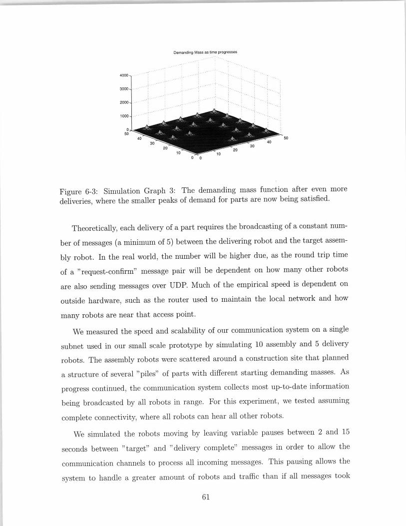
Demanding Mass as time progresses
4000-
3000-
2000-
0 5
0 0
Figure 6-3: Simulation Graph 3: The demanding mass function after even moredeliveries, where the smaller peaks of demand for parts are now being satisfied.
Theoretically, each delivery of a part requires the broadcasting of a constant num-
ber of messages (a minimum of 5) between the delivering robot and the target assem-
bly robot. In the real world, the number will be higher due, as the round trip time
of a "request-confirm" message pair will be dependent on how many other robots
are also sending messages over UDP. Much of the empirical speed is dependent on
outside hardware, such as the router used to maintain the local network and how
many robots are near that access point.
We measured the speed and scalability of our communication system on a single
subnet used in our small scale prototype by simulating 10 assembly and 5 delivery
robots. The assembly robots were scattered around a construction site that planned
a structure of several "piles" of parts with different starting demanding masses. As
progress continued, the communication system collects most up-to-date information
being broadcasted by all robots in range. For this experiment, we tested assuming
complete connectivity, where all robots can hear all other robots.
We simulated the robots moving by leaving variable pauses between 2 and 15
seconds between "target" and "delivery complete" messages in order to allow the
communication channels to process all incoming messages. This pausing allows the
system to handle a greater amount of robots and traffic than if all messages took
61

place within a few seconds of each other, but it is still an underestimate compared to
the real amount of time required for robots to move about, and therefore only lower
bounds the effectiveness of the system.
Using this evaluation of the communication system, we demonstrated that robots
could successfully choose the correct locations to drop off parts and negotiate among
each other for delivery rights. After many iterations, the largest stack of required
parts has dropped as delivery robots receive and parse the messages from the assembly
robots close to the large stack, displayed in Figure 6.1. In addition, the delivery robots
also have delivered parts to other places on the map when they get the response
that the assembly robot with the true highest need is already occupied, preventing
wasted time. In addition, no delivery robot tries to deliver the same part as another
because each robot keeps its map synchronized based on the messages it hears from
others. The message protocol for each of simulated deliveries took on the order of a
few seconds each, plenty of time given the much slower larger scale system time for
picking up parts and moving around the construction site.
6.2 Full Platform Testing
6.2.1 Setup
For evaluating how well the prototype system delivers parts, we chose a single scenario
demonstrating different features of a real system and ran the system, changing the
number and locations of the assembly robots for different runs to demonstrate correct
behavior. We set up 2 delivery robots and 2 assembly robots. One delivery robot only
delivered red "connector" pieces, and one delivery robot delivered blue "truss" pieces.
We placed the assembly robots at the locations on the map where an implemented
version of our distributed assembly controller (see Section 4.2.2) would have placed
them, right next to the blueprint location of the towers of parts.
The blueprint for each run of the scenario remained the same (shown side by
side with demanding mass function in Figure 6-4 , but various other factors changed

You give me a part
Searching for truss
IV$ 11
4W,1:1
X,OseN I Mta
Figure 6-4: The test scenario uses a symmetric initial demanding mass distribution.Assembly robots, (shown in green in the GUI) begin positioned at the points of highestdemanding mass, which are the points at the construction site that need parts themost according to the blueprint.
between test runs to evaluate adaptability. The 4 robots stayed in a 5x5 meter
rectangle, so the VICON motion capture system could detect their movements and
relay the robots their position information. The supply dock was always located at
position (0,0), but the parts at the supply dock were moved around to test the robots'
ability to pick up reachable parts. The two different delivery robots started at random
locations in the middle of the field for each test. The assembly robots split the field

between them, but some runs of the scenario involved moving or turning off one of the
assembly robots. This movement of the assembly robots caused the delivery robots
to adapt, delivering parts only to the remaining robot, or to the robot that was now
closer to the desired blueprint location of the components being delivered. We placed
multiple parts, powered by 3.7V batteries, in the semi-circle shaped supply dock for
the delivery robots to find and pick up. We placed both red joint parts and blue truss
parts down, and the robots had no trouble telling them apart using communication
with the parts.
6.2.2 Scenario Completion
The first goal of the scenario, where two assembly robot locations begin with the
same high demanding mass, was designed to test load balancing. In an ideal setup
and execution, the delivery robots alternate between the two assembly robots. To
test adaptivity, we also ran a variation in which one robot stops demanding parts
halfway through the test, even if it had a higher demanding mass.
We ran the scenario with two assembly robots on the platform 12 times. All runs
produced the correct "alternating" delivery behavior. Both the joint delivery robot
and the truss delivery robot alternated targets and delivered to both assembly robots,
seen in the video screenshots in Figure Sequence6-5 We ran the scenario with the
assembly robots located at less-than-optimal positions for demanding mass 3 times.
The delivery robots responded with the desired behavior, i.e. they still delivered
parts to the robot with the highest relative demanding mass, and the delivery of
parts resulted in an overall lowering of demanding mass around the construction site.
We ran the same scenario as before 3 times with a simulated "failure", in which
one of the assembly robots was taken off the map. Even when the assembly robot
removed had a higher demanding for parts, its failure resulted in the delivery robots
delivering to the remaining robot.
Over all 12 test scenario runs, the 2 delivery robots attempted 50 deliveries and
completed 48 of them. The two failed deliveries were the result of arm hardware
failures because of dropped parts after leaving the supply dock. In all cases, the

communication between delivery and assembly robots confirmed the deliveries and
changed the demanding masses of the assembly robots.
6.2.3 Test Run Time Breakdown
The test runs of the robots involved the two delivery robots moving to the supply
dock, searching for a part at the supply dock, picking up a part of the correct type,
moving to a random map point to promote even delivery (as noted in Section 4.2.1),
communicating with an assembly robot, and delivering the part to a target assembly
robot. Over 50 runs, each robot took 8 minutes, 39 seconds to make a round trip to
move from somewhere in the construction site to the supply dock and then deliver
the part. Of all the deliveries, 48 out of 50 of them were successful. The failure mode
for the remaining 2 failed part deliveries
The longest recorded run of the system using two delivery robots resulted in a
delivery system active for more than 70 minutes. In this time, the delivery robots
delivered 13 parts to the stationary assembly robots out of 14 attempted deliveries.
The run ended when the power ran out of battery of one of the arms on the delivery
robots. The failed delivery occurred when a delivery robot's gripper dropped a part
that it had retrieved and failed to notice that it had dropped the part. This run
indicates that system's primary limitation in terms of time working is related to
battery power.
Analysis of the test run time shows that the robots spent a significant amount of
time parked in the supply dock, searching for parts. Of this time, on average, the
robotic arm requires 02:46 to search for, find, and pick up the correct type of part.
On average, each robot spent 32% of each delivery run searching for the part at the
supply dock. This large amount of time caused a backup in the system. Indeed, for
all test runs in which both delivery robots ran at once, each delivery robot spent
an average time of 2:34 per delivery sitting and waiting for the other delivery robot
to move out of the way. This is consistent with observations for the test runs in
which only one delivery robot operated, which show an average round trip delivery
time of only 6:54, an immediate 20% time decrease. This large chunk of time has

implications for the parallelization of the system (discussed in Section 7.2), because
this search time means that a delivery robot waiting for the supply dock to be freed
would complete a delivery, then sit and do nothing while waiting for the supply dock
to be cleared.
6.2.4 Test Run Communication Breakdown
The test runs of the robots required that delivery robots communicate with assem-
bly robots in order to confirm the delivery of a part to the assembly robots. When
not engaged with a specific delivery robot making a delivery, each assembly robot
broadcasts a desire for a part delivery at a rate of 1Hz to alert any nearby delivery
robot. This was sufficiently often that delivery robots trying to complete deliveries
could listen for assembly robots asking for a delivery and respond. Communication
between a delivery robot and an assembly robot was implemented with UDP multi-
cast broadcasting, and was completely asynchronous. To achieve communication, we
required the rebroadcasting and acknowledgement of all messages between 2 robots.
Over all test runs, on each round trip delivery, the delivery robot required 4.8 message
packets total to deliver 2 messages to the target assembly robot, meaning each mes-
sage from a delivery robot had to be resent at least once on average before a response
was received from a target assembly robot. However, during the average delivery,
each assembly robot sent out an average of 180.5 messages since the assembly robots
spend much of each delivery robot's delivery round spamming out one message per
second asking for parts.

Demanding Mass for Connectors Al Test Run Start
700- .600
-D - - 0
500--
400- 400
300
1000
5 00
5 -5
X Position in MetersY Position in Meters
Demanding Mass for Connectors After I Delivery
Y Positio in MetersX Position in Meters
Dernanding Mass for Connectors Alter 1 Deliery
Assembly Robot 5 bot4 WRed PartDelitary Robot
2nd Red Connector Pee Y Position i MetersX Posio Meters
Demanding Mm oter Conn ers Ae 2 D.eloiIs
Assembly RooH -byRbot 4 Red Part.Delivery Robot **
1st Red Connector W20
2nd Red Connector Piece """"'P'"
Figure 6-5: The photos on the right show video stills from a test run of the "evendelivery" scenario. The graphs to the left of each photo show the demanding massaround the map at the time of the photo. During the run, assembly robots beginpositioned at 2 different points of highest demand for parts. As the red connectorparts are delivered, first to robot 5, then to robot 4, the maximum demanding massfor the entire map changes, causing the delivery robot to change delivery targets. Fullvideo data available at [2] 67

68

Chapter 7
Lessons Learned
We learned several lessons from the design, building, testing and analysis of the
platform. First, design focused on accuracy rather than efficiency led to an accurate,
but slower moving system, and the building of the system is evaluated accordingly.
Second, analysis of the time each robot spent moving around the construction site
during test runs points to some practical concerns in developing real distributed
robotic systems. Thirdly, design and building of the system led to some modifications
of a theoretical algorithm to make it implementable in practice.
The main differences between the theory and implementation for each part of the
system are:
1)Localization: the theoretical algorithm assumes accurate instantaneous location
information available about all robots to all robots. In the actual physical implemen-
tation, we use an external localization system that provides location information at
the rate of 10 Hz with a precision of +/- 1 millimeter.
2) Mobility: theoretical, smooth moving robots use constantly available, instanta-
neous location information to move smoothly, but the physical iCreate mobile robot
platform could not instantly change speeds or direction, and sending speed changes to
the iCreate had a maximum rate of 5Hz before the mobile platform did not respond
to the speed changes.
3) Motion Planning: theory assumes robots are points with a radius of 0. They
are unconcerned with collisions and pass invisibly through both smart parts and other

robots on the map. The real robots had a radius of more than 25cm and implemented
multi-robot collision avoidance, which greatly affects the robot trajectories.
4) Communication: the theoretical algorithm assumes instantaneous message
transmission with no communication error. Our platform's implementation used
UDP multicast, capable of dropping and misinterpreting packets. It required an error
tolerant communication protocol implemented with acknowledgements and multiple
message copies sent.
5) Demanding Mass Representation: the theoretical division of demanding mass
around a construction site divided the map into discrete quantities of demanding
mass such that only robots in a certain grid had demanding mass, which led to point
robots located directly on top of where parts should be placed. Since two objects
cannot actually occupy the same space, the physical implementation used Gaussian
density functions to calculate demanding mass in order to allow physical assembly
robots to calculate demanding mass while nearby a spot on the map that needed
parts.
6) Grasping: The theoretical algorithm assumed instantaneous part manipulation
and assumed that parts were never lost or dropped. The physical implementation
required an average of 2:34 to pick up a part, and required more error checking to
ensure that parts were not dropped.
7.1 System Speed and Robustness
The designed platform, with robots running on iRobot iCreate mobile platforms, uses
slow moving robots even by the standard of those mobile platforms because of the
accuracy desired by the robots in picking up and moving parts. Receiving accurate
position data and using a position based controller works best if the mobile robot
is given time to move slowly to the desired position without overshooting. This
approach worked well for our robots. We found that the speed of the robots was
less important than keeping the robots from accidentally running into one another
because of accidental position overshoot error, and even more importantly, a slow

speed allowed the robots to stop within 2cm of a desired position before manipulating
parts. This precision was crucial in placing parts at the desired location and will
continue to be important in future work with the platform as the robots begin placing
parts on top of each other.
7.2 Test Run Analysis Reveals New Parallelization
Perspective
As discussed in Section 6.2.3, the delivery robots, while displaying correct behavior,
spent 1/3 of the time on each delivery run obtaining a part from the single supply
dock, forcing other delivery robots to wait before they could obtain their own parts
to deliver. The addition of a second delivery robot, while decreasing the total number
of parts delivered per minute, increased the round trip time of an individual robot
by more than 1 minute, or more than 20%. On average, a delivery robot working
around another delivery robot spent more than 25% of each trip waiting in place for
the supply dock to be cleared. This observation has implications for how platforms
that rely on sources of supplies must be designed in practice.
The bottleneck caused by a supply dock may be a small or large problem, requiring
either a simple or a complex solution based on the design of the rest of the system.
First, the supply dock may not cause a bottleneck at all. Our test construction site
was small. At a very large construction site, part delivery may take long enough
that the delivery robots do not spend enough time at the supply dock to cause a
bottleneck. Second, a bottleneck may be solvable by adding more supply sources.
The simplest solution to the problem is to add a supply docks for every delivery robot.
In practice, this might involve taking supplies shipped in bulk to a construction site
and spreading them out for the delivery robots to reach, or supplying delivery robots
from their own charging stations. Third, if spreading out supplies is not a feasible
option for a construction, supply docks must be designed that allow more than one
robot to access them at once, or supply docks must allow the delivery robots to pick

up their payloads more quickly. This solution will change based on the situation,
but our platform's evaluation brought the matter to our attention as a design issue
worthy of consideration, since the original system model neglected the supply dock's
significance.
7.3 Theory and Practical Implementation of a Dis-
tributed Algorithm
Although the original algorithm and simulation of this problem were complete and
proven correct, the implementation of the algorithm resulted in some changes to the
original problem model. The original algorithm that inspired the building and evalu-
ation of this platform modeled the problem of delivering parts around a construction
site as a mutation of a network coverage problem [6]. Assembly robots spread out
across a blueprint and asked nearby delivery robots to deliver parts to them. While
this high-level algorithm did not change, many lower level practical details did change
over the course of the implementation.
Many of the changes in the original algorithm occurred due to levels of abstraction
in the problem statement. In the original high-level algorithm, the robots acted
as point masses. They passed through each other and through the parts already
delivered and the parts destined to be assembled into a structure. We implemented
collision avoidance at a low level, which did not affect the high level algorithm at all.
More difficult to adjust was the fact that robots in the original algorithm did not
plan to avoid parts that had already been placed on the map. They also modeled a
structure as a 2-dimensional object in which no parts depended on any other parts
already being in place at a construction site. The implemented model for a blueprint,
however, includes part dependencies when calculating how many parts an assembly
robot should demand (Section 4.1.2). The implemented blueprint model keeps track
of specific parts, not just quantities of parts, as a way of planning which parts should
be delivered next.
The second major difference between the high level algorithm and implementation
involved the way that the robots used the supply dock. Obtaining and manipulating
parts required no time in simulation, and since robots could pass through other robots,
the part supply dock was treated as a black box. However, in practice, the supply
dock caused a bottleneck in the platform (Sections 6.2.3 and 7.2). Our system used
intelligent parts that allowed delivery robots to be more accurate in picking up parts,
and finding the correct parts using IR beacons takes more time than picking up parts
instantly as in the high level algorithm.
Communication required more lower level consideration since the original algo-
rithm required guaranteed, synchronous communication to give all robots complete
information about their surroundings. In the implementation, we replaced guaranteed
communication with a messaging system based on acknowledgements and the concept
of logical time. Our system kept track of the most recent messages received from sur-
rounding robots. Robots using the communication protocol ensured recent, accurate
information by deleting out-of-date information and not moving forward until fresh
messages arrived. Replacing guaranteed communication with a UDP broadcasting
system capable of dropping packets meant that messages had to be sent and received
multiple times in order to confirm their contents.
All these lower level implementations changed the specifics of how the robots
moved and interacted. They also changed the timing of various steps in the tasks
to be completed, but the high level algorithm for delivering parts fairly around the
construction site remained intact.

74

Chapter 8
Conclusion and Future Work
The development of this platform resulted in a set of 4 hardware robots and a software
system capable of delivering parts around a test construction site using coordination,
task planning, and interaction with intelligent parts. After observation and evalua-
tion, suggestions are given for how system can be improved both in hardware and in
software. Future work based on the platform will involve using the robots to manip-
ulate parts into structures and expanding the number of robots and parts used in the
system.
8.1 Part Delivery Improvements based on Test Re-
sults
The evaluation of this platform resulted in observations on how the hardware, specif-
ically that relating to part manipulation, could be improved further. First, part
manipulation, while currently very accurate, takes time because each robot arm has
only one IR beacon for communicating with the parts that the arm is trying to pick
up. The part manipulation could be sped up be adding an additional IR transmitter
to the end of the arm, allowing more space to be searched at once and allowing the
robot to zero in on a part more quickly. Second, since delivery robots spend time
waiting for the supply dock to be available, speeding up the round trip time required

for part delivery could be achieved by adding more supply docks to the platform.
This would greatly reduce the wait time of delivery robots, and would allow more
time to be spent moving about the construction site instead.
8.2 Using the Platform to Build Structures
Figure 8-1: Computer model of a goal structure to build using the platform.
Future work using this platform will involve stacking and combining the different
types of parts that the system produces. Our delivery robots will hand off parts to the
(stationary in this version) assembly robots, who will move the parts into their final
positions, coordinating to assemble a cube or series of cubes like the one in Figure 8-1.
The assembly robots will use the already developed platform, including the mobile
platform and accompanying motion controller, the part manipulation platform and
its methods of searching for parts, and the communication protocol for transmitting
and acknowledging other robots' messages. The assembly robots will use the current
platform's blueprint and demanding mass function to negotiate among themselves

and split the work required for assembling a structure among themselves. They will
then ask the implemented delivery robots for the proper parts, and move around
the site continuing construction based on the blueprint's updated demanding mass
function, as touched on in Section 4.2.2.
8.3 Final Conclusions and Lessons Learned
This platform required mobile, autonomous robots that could interact with each
other and their environment. The high level algorithms that planned the robots' au-
tonomous tasks made many simplifying assumptions about the system, but actually
developing a working physical system outside of simulation required making adjust-
ments to the original plans. In order to make the platform demonstrate the desired
algorithmic behavior, we combined the high-level algorithms controlling the actions
of the robots with lower level controllers for viable communication channels, stable
robot localization and navigation, crash avoidance, and part manipulation. The re-
sulting system demonstrated a use for distributed robotics in industry that involved
distributed control, autonomous and mobile robots, and an active ability to change
their environment.

78

Appendix A
Tables
Table A. 1: The unit cost of creating a single prototype robot
Part Unit CostiRobot iCreate base and 14 volt battery $130 USDCrustCrawler SG5 Arm $500 USD9 Volt Arm Rechargeable Battery $2 USDIR Sensor Chip $50 USDDell Mini Inspiron 10 $315 USDxBee Receiver Module $70 USD

Table A.2: Additional system costs
Part Unit CostIR Chip for Smart Part $50 USD per PartIR Chip Battery Power for Smart Part $4 USD per PartLocal Wireless Network Router $50 USDProviding xy-plane position and rotation data to robots using motion capture Unmeasurable

Bibliography
[1] J. Cortes, S. Martinez, T. Karatas, and F. Bullo. Coverage control for mobilesensing networks. IEEE Transactions on Robotics and Automation, 20(2):243-255, April 2004.
[2] MIT CSAIL Distributed Robotics Laboratory. Collected data: testruns of the distributed robotic assembly platform. Online Video, 2009.http: //web. mit . edu/enneirda/Public/RobotDataVideos/.
[3] Matthew Faulkner. Instrumented tools and objects: Design, algorithms, andapplications to assembly tasks. Master's thesist, Massachusetts Institute of Tech-nology, CSAIL Distributed Robotics Laboratory, June-August 2009.
[4] Scott Kirsner. Robots on the move. Boston Globe, Au-gust 31 2008. http://www.boston.com/business/technology/articles/2008/08/31/robots-onthe-move/.
[5] Seung kook Yun and Daniela Rus. Optimal distributed planning of multi-robotplacement on a 3d truss. In Proc. of IEEE/RSJ International Conference onIntelligent Robots and Systems, San Diego, USA, October 2007.
[6] Seung kook Yun, Mac Schwager, and Daniela Rus. Coordinating construction oftruss structures using distributed equal-mass partitioning. In Proc. of the 14thInternational Symposium on Robotics Research, Luzern, Switzerland, Aug 2009.
[7] M. Bollini B. Charrow A. Clayton F. Dominguez K. Donahue S. Dyar L. JohnsonH. Liu A. Patrikalakis J. Smith M. Tanner L. White D. Rus N. Correll, A. Bolger.Building a distributed robot garden. In IEEE/RSJ International Conference onIntelligent Robots and Systems (IROS), St. Louis, MO, 2009.
[8] M. Schwager, J. McLurkin, J. J. E. Slotine, and D. Rus. From theory to practice:Distributed coverage control experiments with groups of robots. In Proceedingsof the International Symposium on Experimental Robotics, Athens, Greece, July2008.
[9] Producer Scott Kirsner. Innovation economy: Kiva systems. Boston Globe OnlineVideo, 2008. http: //www. kivasystems. com/bg. html.
81

[10] Jean-Claude Latombe. Robot Motion Planning. Kluwer Academic Publishers,Norwell, MA, USA, 1991.
[11] Justin Werfel and Radhika Nagpal. International journal of robotics re-
search. Three-dimensional construction with mobile robots and modular blocks,3-4(27):463-479, 2008.
[12] Marco Pavone, Emilio Frazzoli, and Francesco Bullo. Distributed algorithms for
equitable partitioning policies: Theory and applications. In IEEE Conference on
Decision and Control, Cancun, Mexico, Dec 2008.
[13] Michael David Mitzenmacher, Michael David Mitzenmacher, and Michael DavidMitzenmacher. The power of two choices in randomized load balancing. Technical
report, IEEE Transactions on Parallel and Distributed Systems, 1996.
[14] MC Nechyba and Y. Xu. Human-robot cooperation in space: SM2 for new
spacestation structure. Robotics & Automation Magazine, IEEE, 2(4):4-11, 1995.
[15] S. Skaff, P. Staritz, and WL Whittaker. Skyworker: Robotics for space assembly,inspection and maintenance. Space Studies Institute Conference, 2001.
[16] Peter J. Staritz, Sarjoun Skaff, Chris Urmson, and William Whittaker. Sky-worker: A robot for assembly, inspection and maintenance of large scale orbitalfacilities. In IEEE ICRA, pages 4180-4185, Seoul, Korea, 2001.
[17] Y. Nakamura and H. Hanafusa. Inverse kinematics solutions with singularityrobustness for robot manipulator control. Journal of Dynamic Systems, Mea-surement, and Control, 25:163-171, 1986.
[18] Yi, Walker, Tesar, and Freeman. Geometric stability in force control, 1991.
[19] Byung Ju Yi, Robert A. Freeman, and Delbert Tesar. Open-loop stiffness controlof overconstrained mechanisms/robotic linkage systems. In Proceedings of theIEEE International Conference on Robotics and Automation, pages 1340-1345,Scottsdale, AZ, 1989.
[20] Robert L. Williams II and James B. Mayhew IV. Cartesian control of VGTmanipulators applied to DOE hardware. In Proceedings of the Fifth NationalConference on Applied Mechanisms and Robotics, Cincinnati, OH, October 1997.
[21] Patrick J. Willoughby and Alexander H. Slocum. Precision connector assemblyusing elastic averaging. Poster presented at 19th Annual ASPE Annual Confer-ence, 2004.
[22] Zefran. Continuous methods for motion planning, 1996.
[23] Zhao. Kinematic control of human postures for task simulation, 1996.
[24] Zinn, Khatib, Roth, and Salisbury. Towards a human-centered intrinsically-saferobotic manipulator, 2002.

Appendix B
Complete Software Code
All software controlling the robots for this platform was written in Java and is avail-
able in an online Subversion repository at :
https ://svn. csail .mit .edu/robotassembly-repo/ABolgerDistributedDeliveryBranch/
The highest level controller of each robot was its task planner. The task plan-
ners differed between the delivery and assembly robots, and both task planners are
reproduced here, showing the finite state machine structure used to transfer control
to different parts of the robot such as the mobility platform or the robotic arm.
AssemblyPlanner.java Tue Feb 02 15:52:13 2010
package planner.constructPlanner;
AssemblyPlanner.java Tue Feb 02 15:52:13 2010
* a map of all the parts with selection
private BluePrint myParts;
java.io.FileWriter;java.io.IOException;java.io.PrintStream;java.io.PrintWriter;java.util.Collection;java.util.Date;java.util.HashMap;java.util.PriorityQueue;java.util.Queue;java.util.Set;
bluePrint.BluePrint;bluePrint.CommunicationTestBlueprint;bluePrint.Part;bluePrint.Position;bluePrint.SimpleBlueprint;bluePrint.Part.PartState;arm.ArmManager;
import planner.constructPlanner.PlannerConstruct.State;import planner.meshNet.*;import navigation.navigator.*;
* currently Unimplemented pending algo discussion.
* @author stein*/
public class AssemblyPlanner extends PlannerConstruct
* the main state of the robot
private State myState;
* the last state of the system*/
private State lastState;
private long lastPromisedPart;
@Overridepublic void setRobotState(State s)
this.myState = s;
* The spot that the assembly planner wants its parts to be delivered to.*/
private double[] desiredTrussDeliverySpot; ;private double[]I desiredConnectorDeliverySpot;
* The parts that have been delivered
private Queue<Part> justDeliveredParts;
* @Override* The mesh manager designed for use with an assembly robot.
importimportimportimportimportimportimportimportimportimport
importimportimportimportimportimportimport
myState = State.WAITFOR_DELIVERY;
myParts = new SimpleBlueprint();
justDeliveredParts = new PriorityQueue<Part>();System.out.println(this. getRobotID) + " Planner: "+meshManager.getCur
rentTime()+" "+new Date()+"Start ");
public AssemblyPlanner(int robotID, brain.RobotBrain.RobotType robotType,Navigator nav, MeshManager mm, ArmManager a, boolean simulated) throws
Exception {
super(robotID, robotType, nay, mm, a);//Make sure we have the right king of MeshManager:if (mm instanceof AssemblyMeshManager) {
meshManager = (AssemblyMeshManager) mm;else {
throw new Exception("Error: You must initialize an Assembly planner with a manager of Java class AssemblyMeshManager");
myState = State.WAITFORDELIVERY;
protected AssemblyMeshManager meshManager;
* constructs the planner by initializing the LCM monitor and storing the* ID.* @return
* @throws Exception
public AssemblyPlanner(int robotID, brain.RobotBrain.RobotType robotType,Navigator nav, MeshManager mm, ArmManager a) throws Exception
super(robotID, robotType, nay, mm, a);//Make sure we have the right king of MeshManager:if (mm instanceof AssemblyMeshManager) {
meshManager = (AssemblyMeshManager) mm;else {
throw new Exception("Error: You must initialize an Assembly planner with a manager of Java class AssemblyMeshManager");

AssemblyPlanner.java Tue Feb 02 15:52:13 2010
if (simulated){//myParts = new CommunicationTestBlueprint(10);myParts = new SimpleBlueprint();
}else{
myParts = new SimpleBlueprint();
justDeliveredParts = new PriorityQueue<Part>();System. out. println(this. getRobotID) + " Planner: "+meshManager.getCurrentTime
()+" "+new Date)+"Start ");
if neccessary does computation and data collection, then blocks until theactions associated with the current state are completed and then moves onto the next state<P>Should be pretty legible as is. brief refresher on turnary operator: <BR><TT>var = boolean?tVal:fVal<BR></tt> is the same as <BR><TT>ifboolean) var = tVal; <BR>else var = fVal; </tt>
public void run()
while (true)try{
//Update our part locations and statuses based on new mesh data:for (String partID : meshManager.getLatestPartLocations().keySet()){
myParts.retrievePartByID(partID).setActualPosition(meshManager.getLatestPartLocations().get(partID));
myParts.retrievePartByID(partID).setPartStatus(PartState.UNKNOWN);
for (String partID : meshManager.allWaitingParts).keySet()){myParts.retrievePartByID(partID).setPartStatus(PartState.ONMA
P);
}catch(Exception e){System. out. println(this. getRobotID) + " Planner: "+meshManager.getCur
rentTime()+" "+new Date()+" Assembly Robot State error updating map:" + e);
case WAIT FOR DELIVERY://Send out requests for pieces every 500ms:try {
Thread.sleep(500);catch (InterruptedException e)
// TODO Auto-generated catch blocke.printStackTrace();
myState = waitfor_delivery() ? State.PICKUPPARTState.WAITFORDELIVERY;
break;
case PICKUPPART:
myState = pick uppart) ? State.PLACEPART: State.PICKUP_PART;
break;case TO_POI: //Move if necessary for assembly.
//TODO: IMPLEMENT THIS.
case PLACE PART:// double[] p2 = computeDroppingLocation(currentPart);if( place part)) {
myState = State.COMPUTEDELIVERY_LOCATION;justDeliveredParts.poll();
}else {myState = State.PLACE_PART;
break;case COMPUTEDELIVERYLOCATION:
//TODO: In the future the assembly robot willlocation after placing each part and recalculating demand.
myState = State.WAITFORDELIVERY;break;
case PAUSE:myState = pause() ? lastState : lastState;break;
case STOP:System.err.println("ALLDONEI");System.exit(0);break;
if (myState 1= State.PAUSE) {lastState = myState;
// /////// //////////////////////STATE MACHINE// ACTIONS//////////////////////////////////////////
// System.out. println(this. getRobotID() + " Planner: "+meshManager.getCurrentTime()+" "+new Date()+" Assumed Part Locations "+ myParts.retrievePartsOnMap));
System.out.println(this.getRobotID() + " Planner: "+meshManager.getCurrentTime)+" "+new Date()+" Assembly Robot State " + myState);
switch (myState) {
private boolean waitfor delivery) {//TODO: figure out exactly which parts are in this robot's partition. For now,
just send out information about all the// parts we know about as well.System. out. println(this. getRobotID() " Planner: "+meshManager.getCurrentTime
()+" "+new Date)+" Truss Mass "+myParts.getTrussMass((int) (navModule.getRobotLocation).getX(
move to this new
AssemblyPlanner.java Tue Feb 02 15:52:13 2010

AssemblyPlanner.java Tue Feb 02 15:52:13 2010 5 AssemblyPlanner.java
)*1000),(int) (navModule.getRobotLocation(.getY()*1000)) +" Connector Mass: "+ myParts.getConnectorMass((int) (navModule
.getRobotLocation().getX()*1000),(int) (navModule.getRobotLocation(.getY()*1000) ));
meshManager.broadcastMyDemandingMass(
myParts.getTrussMass((int) (navModule.getRobotLocation().getX()*1000),(int) (navModule.getRobotLocation().getY()*1000)),
myParts.getConnectorMass((int) (navModule.getRobotLocation().g }etX()*1000),(int) (navModule.getRobotLocation().getY()*1000) ), }
navModule.getRobotLocation().getX() , navModule.getRobotLocation().getY (),
navModule.getRobotTheta(), myParts.retrievePartsOnMap());
//Check to see if we got a response:
//Acknowledge things that SHOULD be delivered:meshManager.acknowledgelntendedDeliveries(myParts.getTrussMass((int) (navModul
e.getRobotLocation().getX()*1000),(int) (navModule.getRobotLocation().getY()*l000)),
myParts.getConnectorMass((int) (navModule.getRobotLocation().getX()*1000),(int) (navModule.getRobotLocation(.getY()*1000) ),
navModule.getRobotLocation().getX(),navModule.getRobotLocation().getY(),navModule.getRobotTheta(),myParts.retrievePlacedParts());
//Get the id of the part that has been delivered:Part delivered = meshManager.getNextDeliveredPart(;if (delivered == null){
//System.out.println(this.getRobotID() + " Part has not been deliveredyet.");
return false;} else {
Part blueprintPart = myParts.retrievePartByID(delivered.getID());blueprintPart.setActualPosition(delivered.getActualPosition());blueprintPart.setPartStatus(Part.PartState.ONMAP);
myParts.placePart(blueprintPart);System.out. println(this. getRobotID() + " Planner: "+meshManager.getCur
rentTime()+" "+new Date()+" Truss Mass "+myParts.getTrussMass((int) (navModule.getRobotLocation
().getX()*1000),(int) (navModule.getRobotLocation().getY()*1000)) +" Connector Mass: "+ myParts.getConnectorMass((int) (n
avModule.getRobotLocation().getX()*1000),(int) (navModule.getRobotLocation().getY()*1000) ));
System.out.println(this. getRobotID() + " Planner: "+meshManager.getCurrentTime()+" "+new Date()+" Part Delivered "+ delivered);
try {PrintWriter pw = new PrintWriter(new FileWriter("mass"+this.ge
tRobotID()+".txt", true));
Tue Feb 02 15:52:13 2010 6
myParts.printBlueprintMass( pw, this.getRobotIDo();pw.flush();pw.close();
catch (IOException e)// TODO Auto-generated catch blocke.printStackTrace();
return true;
private boolean pick uppart()/*
//Make sure we have the latest network data on obstacles that might be in ourway
//before moving://TODO: Hook up the navigation module CORRECTLY to the blueprint. THIS IS A HA
CK.for (bluePrint.Position p : meshManager.getLatestPartLocations().values(){
navModule.addPartToMap(p.getX()/1000.0, p.getY()/1000.0);
if (justDeliveredParts.peek() 1= null){double[] goal = computeDroppingLocation(justDeliveredParts.peek());navModule.goToPose(goal(O], goal[l], goal[2]);return armModule.findAndGrab(justDeliveredParts.peek().getType());
}else return false;
return true;
private boolean placepart()/*double(] goal = new double[] {justDeliveredParts. peek(). getDesiredPosition(). ge
tX()/1000.0,justDeliveredParts. peek(). getDesiredPosition() . getY( ) /1000.0,justDeliveredParts.peek() .getDesiredPosition() .getTheta( )/1000
.0
if (navModule.goToPose(goal[0], goal[l], goal(2])) {Part blueprintPart = myParts.retrievePartByID(justDeliveredParts.peek(
).getID());
//TODO: THIS IS JUST AN ESTIMATE OF WHERE THE PART ENDS UP. IT NEEDS T0 BE MORE ACCURATE:
double armOffset = .4;double xEstimate = this.navModule.getRobotLocation().getX() + (armOffs
et)*Math.sin(this.navModule.getRobotTheta()) ;double yEstimate = this. navModule. getRobotLocation(). getY() + (armOffs
et)*Math.cos(this.navModule.getRobotTheta()) ;double thetaEstimate = this.navModule.getRobotTheta();//The parts work in mm, so round and multiply by 1000:Position pos = new Position((int) (xEstimate*1000), (int) (yEstimate*l
000), 0, (int) (thetaEstimate*1000), true, meshManager.getCurrentTime());
blueprintPart.setActualPosition(pos);blueprintPart.setPartStatus(Part.PartState.FINAL_POSITION);
myParts.placePart(blueprintPart);

Tue Feb 02 15:52:13 2010
return armModule. putDownPart(blueprintPart. getType());
elsereturn false;
*///For now, just acknowledge.return true;
private boolean pause()return false;
/* *
* returns true when the STOP state is reached
public boolean stop()return myState State.STOP;
@Overridepublic State getRobotState()
return myState;
@Overridepublic Collection<Part> getParts()
return this.myParts.retrievePlannedParts();
public static void main (String[] args){try {
AssemblyMeshManager amm = new AssemblyMeshManager(5);AssemblyPlanner p = new AssemblyPlanner(5,
brain.RobotBrain.RobotType.ASSEMBLY,new RobotNavigator(5, false),amm,null,true);
System.out.println(p.getParts());amm.broadcastMyBlueprint(p.getParts());
p.run();catch (Exception e)
// TODO Auto-generated catch blocke.printStackTrace();
AssemblyPlanner.java
DeliveryPlanner.java Tue Feb 02 15:52:13 2010
package planner.constructPlanner;
DeliveryPlanner.java Tue Feb 02 15:52:13 2010 2
java.awt.Polygon;java.awt.Robot;java.util.ArrayList;java.util.Collection;java.util.Date;java.util.HashMap;java.util.List;
bluePrint.BluePrint;bluePrint.CommunicationTestBlueprint;bluePrint.Part;bluePrint.Position;bluePrint.SimpleBlueprint;bluePrint.Part.PartState;bluePrint.Part.PartType;brain.RobotBrain.RobotType;
private DeliveryMeshManager meshManager;
* the main states of a Delivery robot* <p>* <ul>
* <li><B>ToSOURCE</B> - robot returns to source and picks up a new* object</li>* <li><B>ToTARGET</B> - robot is moving to a randomly selected point* (using the DensityFunction module) and deliver the part to the neediest* assembly robot</li>* <li><B>ToASSEMBLY</B> - robot delivers part to assembler with highest* demanding mass within range.</li>* <li><B>IDLE</B> - robot is ready to start going to source</li>* <li><B>STOP</B> - the stopping state of the robot</li>* </ul>
import navigation.navigator.Locatable;import navigation.navigator.Navigator;import arm.ArmManager;
import planner.environment.DensityFunction;import planner.meshNet.*;
* A Planner is the main top-level FSM for a* robot interactions.h
DRG robot. It only controls single
* @author stein
public class DeliveryPlanner extends PlannerConstruct
@Overridepublic State getRobotState() {
return myState;
* a map of all the parts with selection
private BluePrint myParts;
* the location of the source node
// TODO: Get source location from the map, not from the planner.private double[] sourceLocation = new double[] { 0.0, 0.0, -Math.PI * .999999 }
* the point of exchange
private double[] pointOfInterest; // = new double[]{2,0,0};private double[] dropoffPoint; // = new double[]{1.75, 0, 0};
private int currentTargetRobot = -1;private ArrayList<Part> currentPayloadToDeliver;
public int getCurrentRobotTarget(){return currentTargetRobot;
* the main state of the robot
private State myState;
* the last state of the system*/
private State lastState;
private boolean simulated = false;private Polygon wholeMapPartition = new Polygon(new int[]{-500,4000, 4000,-500}, new i
nt[]{-2000, -2000, 2000, 2000}, 4);
public DeliveryPlanner(int robotID, brain.RobotBrain.RobotType robotType,Navigator nav, MeshManager mm, ArmManager a, boolean simulation){
super(robotID, robotType, nay, mm, a);
if (mm.getClass().equals(DeliveryMeshManager.class)) {meshManager = (DeliveryMeshManager) mm;
}else {try {
throw new Exception("WARNING- THISCLASS OF MESH MANAGERI EXPECT BAD BEHAVIOR!");
catch (Exception e)// TODO Auto-generated catch blocke.printStackTrace(;
IS NOT THE CORRECT
currentPayloadToDeliver = new ArrayList<Part>();simulated = simulation;if (simulated){
myState = State.COLLECT DATA;myParts = new CommunicationTestBlueprint(10);//Simulated map is much, MUCH bigger than the real map area.wholeMapPartition = new Polygon(new int(]{0,51*1000, 51*1000,0
new int[]{0, 0, 51*1000, 51*1000}, 4);
}else{
importimportimportimportimportimportimport
importimportimportimportimportimportimportimport

DeliveryPlanner.java
artID));
System. out. println( this. getRobotID() +" Planner: "+meshManager.getCurrentTime()+" "+new Date()+" Robot "+this.getRobotID( )+" Start");
constructs the planner by initializing the LCM monitor and storing the*ID.
Tue Feb 02 15:52:13 2010 4
p.setActualPosition(meshManager.getLatestPartLocations().get(p
p.setPartStatus(PartState.UNKNOWN);
System.out.println( this. getRobotID() +" Planner: "+meshManager.getCurrentTime()+" "+new Date()+" Updating map for:" + partID);
}catch (Exception e){System.out. println(this. getRobotID() +" Planner: "+meshManager
.getCurrentTime()+" "+new Date()+" Tried to update map concurrently and failed.");
public DeliveryPlanner(int robotID, brain.RobotBrain.RobotType robotType,Navigator nay, MeshManager mm, ArmManager a) {
super(robotID, robotType, nay, mm, a);
if (mm.getClass().equals(DeliveryMeshManager.class)) {meshManager = (DeliveryMeshManager) mm;
}else {try {
throw new Exception("WARNING- THIS IS NOT THE CORRECT CLASS OFMESH MANAGER! EXPECT BAD BEHAVIOR!");
catch (Exception e)// TODO Auto-generated catch blocke.printStackTrace();
)+" "+new Date(
/ientTime()+"
entTime( )+"
currentPayloadToDeliver = new ArrayList<Part>();myState = State.TOSRC;myParts = new SimpleBlueprint();System.out. println(this. getRobotID() +" Planner: "+meshManager.getCurrentTime(
)+" Robot "+this.getRobotID()+" Start");
* if neccessary does computation and data collection, then blocks until the* actions associated with the current state are completed and then moves on* to the next state*<P>
* Should be pretty legible as is. brief refresher on turnary operator: <BR>* <TT>var = boolean?tVal:fVal<BR></tt> is the same as <BR>* <TT>* if(boolean) var = tVal; <BR>* else var = fVal; </tt>*/
public void run()
while (true)//Update our part locations based on new mesh data:
try {
for (String partID : meshManager.getLatestPartLocations().keySet()){Part p = myParts.retrievePartByID(partID);
ng to handshake
AKE_PART;
System.out.println(this.getRobotID() +" Planner:"+new Date()+" Assumed Part Locations "+ myParts);
System.out.println(this.getRobotID() +" Planner:"+new Date()+" Delivery Robot State " + myState);
"+meshManager. getCurr
"+meshManager. getCurr
switch (myState)case IDLE:
if (simulated) myState = State.COLLECTDATA;else myState = State.TOSRC;break;
case TO SRC:
myState = to src() ? State.LOOKEFORPART : State.TOSRC;break;
case LOOK FOR PART:
myState = look for_part() ? State.TO_POI : State.LOOKFORPART
case TO POI:
myState = topoi() ? State.COLLECTDATA : State.TOPOI;break;
case COLLECT DATA:
myState = collectdata() ? State.BROADCAST_INTENTState.COLLECT_DATA;
break;
case BROADCAST INTENT:
try {//Don't just spam the network with messages while tryi
Thread.sleep(500);
catch (InterruptedException e)// TODO Auto-generated catch blocke.printStackTrace();
}myState = broadcastintent() ? State.GO TO DROPPOINT
State.BROADCASTINTENT;break;
case GOTO DROP POINT:
if (simulated) myState = State.HANDSHAKE_PART;else myState = goto droppoint() ? State.DELIVERPART
: State.COLLECT_DATA;break;
case DELIVERPART:
myState = deliverpart() ? State.HANDSHAKE_PART : State.HANDSH
break;
DeliveryPlanner.java Tue Feb 02 15:52:13 2010 3
myParts = new SimpleBlueprint();

DeliveryPlanner.java Tue Feb 02 15:52:13 2010
case HANDSHAKE PART:try {
ng to handshake
umber of seconds.
ATA: State.HANDSHAKE_PART;
te. HANDSHAKEPART;
DeliveryPlanner.java
//Don't just spam the network with messages while tryi
Thread.sleep(500);catch (InterruptedException e)
// TODO Auto-generated catch blocke.printStackTrace();
if (simulated){//Simulate moving and "delivering" here by pausing a n
try {Thread.sleep(Math.round(Math.random()*15000));
} catch (InterruptedException e)e.printStackTrace();
myState = handshakedeliveredpart() ? State.COLLECT_D
else myState = handshakedelivered part() ? State.TOSRC : Sta
break;case PAUSE:
myState = pause() ? lastState : lastState;break;
case STOP:System.err.println("ALLDONEI");break;
if (myState 1= State.PAUSE) {lastState = myState;
}
// ////////////////////////////////STATE MACHINE
// ACTIONS///////I////////////////////////////////////
private boolean tosrc()
//Make sure we have the latest network data on obstacles that might be in our
//before moving://TODO: Hook up the navigation module CORRECTLY to the blueprint. THIS IS A HA
// Right now, during movement, the map can't be updated. THIS MUST BE FIXEDIfor (bluePrint.Position p : meshManager. getLatestPartLocations().values()){
navModule.addPartToMap(p.getX()/1000.0, p.getY()/1000.0);
}
navModule.setNavigationErrorTolerance(.06);navModule.goToPose(sourceLocation[0]+.3, sourceLocation[1], sourceLocation[2]);navModule.setNavigationErrorTolerance(.05);
return navModule. goToSource( sourceLocation[ 0], sourceLocation[1], sourceLocation[2]);
Tue Feb 02 15:52:13 2010
private boolean lookforpart()navModule.setNavigationErrorTolerance(.15);
if (getType() == RobotType.CONNECTORDELIVERY)// Try to grab a part:while (larmModule.findAndGrab(PartType.CONNECTOR))
continue;
}// Back up while holding part:
navModule.goToPose(sourceLocation[0] + .3, sourceLocation(1],sourceLocation[2] + Math.PI);
return true;} else if (getType() == RobotType.TRUSSDELIVERY)
while (larmModule.findAndGrab(PartType.TRUSS))continue;
// Back up while holding part:// navModule.goToPose(sourceLocation(0]
// sourceLocation[2]);
return true;
+ .3, sourceLocation[l],
return false;
}
private boolean topoi() {navModule.setNavigationErrorTolerance(.15);
//Make sure we have the latest network data on obstacles that might be in ourway
//before moving://TODO: Hook up the navigation module CORRECTLY to the blueprint. THIS IS A HA
CK.for (bluePrint.Position p : meshManager.getLatestPartLocations().values()){
System.out.println(this.getRobotIDo() +" Planner: "+meshanager.getCurrentTime()+" "+new Date()+" Adding parts to map:" + p );
navModule.addPartToMap(p.getX()/1000.0, p.getY(/1000.0);}
//Select a random point on the map:Locatable rand = navModule.getRandomReachableMapPoint();System.out.println(this.getRobotID() +" Planner: "+meshManager.getCurrentTime(
)+" "+new Date()+" Selected Random Point:" + rand.getX() + " " + rand.getY();
pointOfInterest = new double[]{ rand.getX(), rand.getY()};
// Go to our point, face away from the source:return navModule.goToPose(pointOfInterest(0], pointOfInterest(1],
sourceLocation[2] + Math.PI);
private boolean collect_data()
//Set the boundaries for where we're going to deliver based on our current location://TODO: Link the polygon we look inside of with the correct map/assembly robots.//For now, just use the whole map as 1 big partition
PartType partType = null;if (getType().equals(RobotType.CONNECTORDELIVERY)) partType = PartType.CONNECTOR;if (getType().equals(RobotType.TRUSSDELIVERY)) partType = PartType.TRUSS;

DeliveryPlanner.java Tue Feb 02 15:52:13 2010
//Listen for at least 2s, or until we have at least 1 target robot:try {
System. out.println(this. getRobotID() +" Planner: "+meshManager.getCurrentTime()+" "+new Date()+"Refreshing and Collecting Data for 2 seconds");
meshManager.resetRobotPartRequestKnowledge();Thread.sleep(2000);
catch (InterruptedException e)// TODO Auto-generated catch blockSystem.out.print("Planner: ");e.printStackTrace();
int targetRobotID = meshManager.getRobotWithHighestDemandingMass(partType, wholeMapPartition);
while (targetRobotID == -1)
// keep listeningtry {
Thread.sleep(1000);catch (InterruptedException e)
e.printStackTrace();
System.out. println(this. getRobotID() +" Planner: "+meshManager.getCurrentTime)+" "+new Date()+" still listening for requests");
targetRobotID = meshManager.getRobotWithHighestDemandingMass(partType,wholeMapPartition);
)+" "+new Date(
currentTargetRobot = targetRobotID;System.out.println(this. getRobotID() +" Planner: "+meshManager.getCurrentTime(
)+" has picked robot "+ currentTargetRobot +" to deliver to.");
//Give a few seconds for robot to recieve latest data on which parts are already floating around.
if (simulated){try {
Thread.sleep(3000 + (int) (Math.random()*15000));catch (InterruptedException e) {
// TODO Auto-generated catch blocke.printStackTrace();
}else {try {
Thread.sleep(2000);catch (InterruptedException e)
// TODO Auto-generated catch blocke.printStackTrace();
for (String partID : meshManager.getLatestPartLocations().keySet ()){myParts.retrievePartByID(partID).setActualPosition(meshManager.getLate
stPartLocations().get(partID));myParts.retrievePartByID(partID).setPartStatus(PartState.UNKNOWN);
System.out. println(this. getRobotID() +" Planner: "+meshManager.getCurrentTime()+" "+new Date()+" Updating map for:" + partID);
int[] robotPos = meshManager.getLatestPositionOfRobot(currentTargetRobot);
if (getType().equals(RobotType.CONNECTORDELIVERY)){Part toAdd = myParts.nextConnector(robotPos[0], robotPos[1]);if (toAdd 1= null){
toAdd.setPartStatus(Part.PartState.BEING_TRANSPORTED);currentPayloadToDeliver.add(toAdd);System. out. println (this. getRobotID() +" Planner: "+meshManager
.getCurrentTime()+" "+new Date()+" Plans on delivering part:" + toAdd.getIDo();
else if (getType).equals(RobotType.TRUSS_DELIVERY)){Part toAdd = myParts.nextTruss(robotPos(0], robotPos[1]);if (toAdd 1= null){
toAdd.setPartStatus(Part.PartState.BEINGTRANSPORTED);currentPayloadToDeliver.add(toAdd);System. out.println(this. getRobotID() +" Planner: "+meshManager
.getCurrentTime()+" "+new Date()+" Plans on delivering part:" + toAdd.getIDo();
return true;
private boolean broadcastintent()PartType partType = null;
if (getType().equals(RobotType.CONNECTORDELIVERY)) partType = PartType.CONNECTOR;if (getType().equals(RobotType.TRUSS_DELIVERY)) partType = PartType.TRUSS;
if (currentTargetRobot 1= -1 ) {
System.out. println(this. getRobotID() +" Planner: "+meshManager.getCurrentTime()+" "+new Date()+" Robot "+ this.getRobotID()+" Delivering to Robot "+currentTargetRobot);
000),
000),
meshManager.broadcastIntendedDelivery(currentTargetRobot,(int) (navModule.getRobotLocation().getX() * 1
(int) (navModule.getRobotLocation().getY() * 1
(int) (navModule.getRobotTheta()*1000),currentPayloadToDeliver.get(0)
//Wait until the part we wanted to broadcast is in the "acknowledged"queue:
DeliveryPlanner.java Tue Feb 02 15:52:13 2010 8

DeliveryPlanner.java Tue Feb 02 15:52:13 2010 9
if (meshManager.partHasBeenAcknowledged(currentPayloadToDeliver.get(0).getID()
// Our exchange point becomes the desired location for us to put down
this part, plus some offset for the arm.//TODO: COMPUTE THIS ARM OFFSET!!IdropoffPoint = new double[]{
currentPayloadToDeliver.get(0).getDesiredPosition().ge
tX() /1000.0,currentPayloadToDeliver.get(0).getDesiredPosition().ge
tY() /1000.0,currentPayloadToDeliver.get(0).getDesiredPosition().ge
tTheta() /1000.0,
System. out. printin(this. getRobotID() +" Planner: "+meshManager.getCurr
entTime()+" "+new Dateo+" Assembly robot " + currentTargetRobot+ " acknowledged target.");
return true;else if (meshManager. partHasBeenRejected(currentPayloadToDeliver. get(0).getI
Do)) {
//Try next best robot:currentTargetRobot = meshManager.getRobotWithHighestDemandingM
ass(partType, wholeMapPartition);System.out.println(this.getRobotID() +' Planner: "+meshManager
.getCurrentTime()+" "+new Date()+" Robot "+ this.getRobotID(+" switched targets to robot "+cu
rrentTargetRobot);
}else{return false;
//TODO: More try/fail fault tolerance can be added here for future wor
//Keep waiting for our part to be acknowledged.return false;
private boolean goto droppoint()//Make sure we have the latest network data on obstacles that might be in our
way//before moving://TODO: Hook up the navigation module CORRECTLY to the blueprint. THIS IS A HA
CK.for (bluePrint. Position p : meshManager. getLatestPartLocations(). values()){
navModule.addPartToMap(p.getX()/1000.0, p.getY()/1000.0);
navModule.setNavigationErrorTolerance(.15);
//Drop off the part NEAR the assembly robot. If we can't find the assembly rob
ot, put the// find someone else to give it to:
int[] robotPos = meshManager. getLatestPositionOfRobot(currentTargetRobot);if (robotPos == null){
Tue Feb 02 15:52:13 2010 10
System. out. println(this. getRobotID() +" Planner: "+meshManager.getCurr
entTime()+" "+new Date()+" No spot for robot "+ currentTargetRobot );
return false;}else {
System.out.printIn(this. getRobotID() +" Planner: "+meshManager.getCurr
entTime()+" "+new Date()+" Going to robot "+ currentTargetRobot+" at "+ robotPos[0]+","+robotP
os[1l);
Locatable dropoff = navModule.getClosestReachableMapPoint(robotPos[0]/1000.0, robotPos[l]/1000.0);
dropoffPoint(0] = dropoff.getX();dropoffPoint(1] = dropoff.getY();
//Make sure we don't try to drop the part on top of the other robot:
dropoffPoint[2] = Math.atan2(dropoffPoint[l] - robotPos[1], dropoffPoi
nt[O] - robotPos[0]) + Math.PI;
System.out.println(this. getRobotID() +" Planner: "+meshManager.getCurr
entTime()+" "+new Date()+" Robot "+ this.getRobotID() +" chose delivery position "+dropoffPoi
nt(0]+","+ dropoffPoint[1]+", "+ dropoffPoint[2]);
navModule.setNavigationErrorTolerance(.08);return navModule.goToPose(dropoffPoint(0],dropoffPoint[1], dropoffPoin
t[2] );
private boolean deliverpart()// Put the part down:
PartType pt;if (getType() == RobotType.CONNECTORDELIVERY)
pt = PartType.CONNECTOR;else
pt = PartType.TRUSS;
armModule.putDownPart(pt);
return true;
private boolean handshakedeliveredpart(){//update our map with where we've put this part://TODO: CHANGE THIS TO WHERE THE PART ACTUALLY IS. FOR NOW THIS IS JUST AN EST
IMATE:double armOffset = .4;double xEstimate = this.navModule.getRobotLocation().getX() + (armOffset)*Math
.sin(this.navModule.getRobotThetao) ;double yEstimate = this. navModule. getRobotLocation(). getY() + (armOff set) *Math
.cos(this.navModule.getRobotTheta()) ;double thetaEstimate = this.navModule.getRobotTheta();
//The parts work in mm, so round and multiply by 1000:
DeliveryPlanner.java

11 DeliveryPlanner.java
Position pos = new Position((int) (xEstimate*1000), (int) (yEstimate*1000), 0,(int) (thetaEstimate*1000), true, meshManager.getCurrentTime());
currentPayloadToDeliver.get(0).setActualPosition(pos);
myParts.placePart(currentPayloadToDeliver.get(0));
meshManager.broadcastCompletedDelivery(currentTargetRobot,(int) navModule.getRobotLocation().getX()*1000,(int) navModule.getRobotLocation().getY()*1000,(int) navModule.getRobotTheta()*1000,currentPayloadToDeliver.get(0) );
//Wait for our acknowledgement before continuing.if (meshManager.partDeliveryHasBeenAcknowledged(currentPayloadToDeliver.get(0)
.getIDO())){System.out.println(this. getRobotID() + Planner: "+meshManager.getCurr
entTime()+" "+new Date()+" Assembly robot " + currentTargetRobot+ " acknowledged delivery: "+ currentPayloadToDeliver.
get(0));
currentPayloadToDeliver.remove(0);return true;
}else {return false;
private boolean pause()try {
Thread.sleep(1000);catch (Exception e)
return false;
return true;
* returns true when the STOP state is reached
public boolean stop() {return myState State.STOP;
@Overridepublic void setRobotState(State s)
this.myState = s;
@Overridepublic Collection<Part> getParts()
return this.myParts.retrievePlacedParts();
DeliveryPlanner.java Tue Feb 02 15:52:13 2010 Tue Feb 02 15:52:13 2010 12