coordinate measuring machine calypso - … refuge surface setting automatic generation of measuring...
TRANSCRIPT

26
Calypso is used for the 3D coordinate measuring machine, and is one of the most highly evaluated software applications in the world. It includes a CAD kernel that ensures unmatched operability.
Improved AI FunctionThe AI function includes three algorithms for automatic element recognition, automatic coordinate system setting, and automatic measuring plane recognition while assisting operators . The AI function supports not only points, straight lines, flat surfaces, spheres, symmetrical points, circles, and cylinders but also cones, ellipses, square holes, and long holes without the need to select the element types before measuring. Simple operation procedures enable successive measurements from measuring one of the elements at random points to pressing the “Terminate” button to stop element measurements .
● Automatic Geometric Element Recognition Our own measuring method and recognition algorithms (patented in Japan and overseas) enable automatic recognition of geometric forms by the direct measurement (probing) of a workpiece. This dramatically reduces procedures to input measuring items .
● Automatic Coordinate System Recognition Measured geometric elements and items required for coordinate system settings (spatial compensation, rotational compensation, origin) are determined automatically and these settings are configured.
Coordinate Measuring Machine Calypso

27
Refuge surface setting
Automatic Generation of Measuring PathCalypso’s safety plane philosophy eliminates the need to input probe path points (intermediate points). Once the bypass boundaries (area around the workpiece) are specified, the probe automatically moves on the safety plane so it does not interfere with the workpiece. For movement on the same surface, another safety plane can be configured to make the amount of movement smaller. The measuring path is generated automatically in accordance with safety plane, supplementary safety plane, number of measuring points, and probing return distance. Measuring path points and probing points can be specified arbitrarily within and between measuring elements, which allows the operator to create the most appropriate measuring path .
Safety plane is created by moving the probe and then clicking the right joystick button .
On-screen Probe Angle Simulator (For Articulating Probe Head)
An operator may wonder whether the probe is oriented correctly after specifying an orientation such as A-axis:0˚, and B-axis: -90˚. The on-screen probe angle simulator provides a screen image of the probe positioned at the input rotation angle and the inclination angle, so the operator can confirm that the desired result has been attained. When CAD data is available, clicking an element automatically changes the ideal probe orientation based on the normal information. This function becomes especially helpful in the case of inclined holes and inclined axes.
RSD Head and Workpiece Simulation Example
Even when CAD data is not available, the orientation of the probe can be changed automatically to the normal direction relative to the actually measured projection plane . An operator used to input the rotation angle while inspecting the workpiece and plans considering interference with the stylus. With the on-screen probe angle simulator, rotation angle settings become simpler than ever before.The stylus simulation function option is required.
Data
Pro
cess
or S
yste
m (S
oftw
are)

28
Compact printout output example
Color scale evaluation of roundness
Diverse Measurement Results
Geometric Element Preview FunctionMeasured geometric elements are iconifi ed. Once these icons are selected, target geometric elements are highlighted on CAD screen and property window of the element appears. In the preview of property window, following commands are executed; input of nominal and tolerance values, number of probing points, and measurement method (scanning or point).
Navigation Function for Measurement ProcedureMeasured geometric elements are iconifi ed and lined up in order of operation procedure. Operators can freely change the order and delete the icons . Once icons are selected, target geometric elements are highlighted on CAD screen and operators can check the measurement procedures .
Geometric Devision Evaluation
Custom printout output example
Flatness evaluation Roundness evaluation Straightness evaluation Flatness evaluation
Custom printout
29
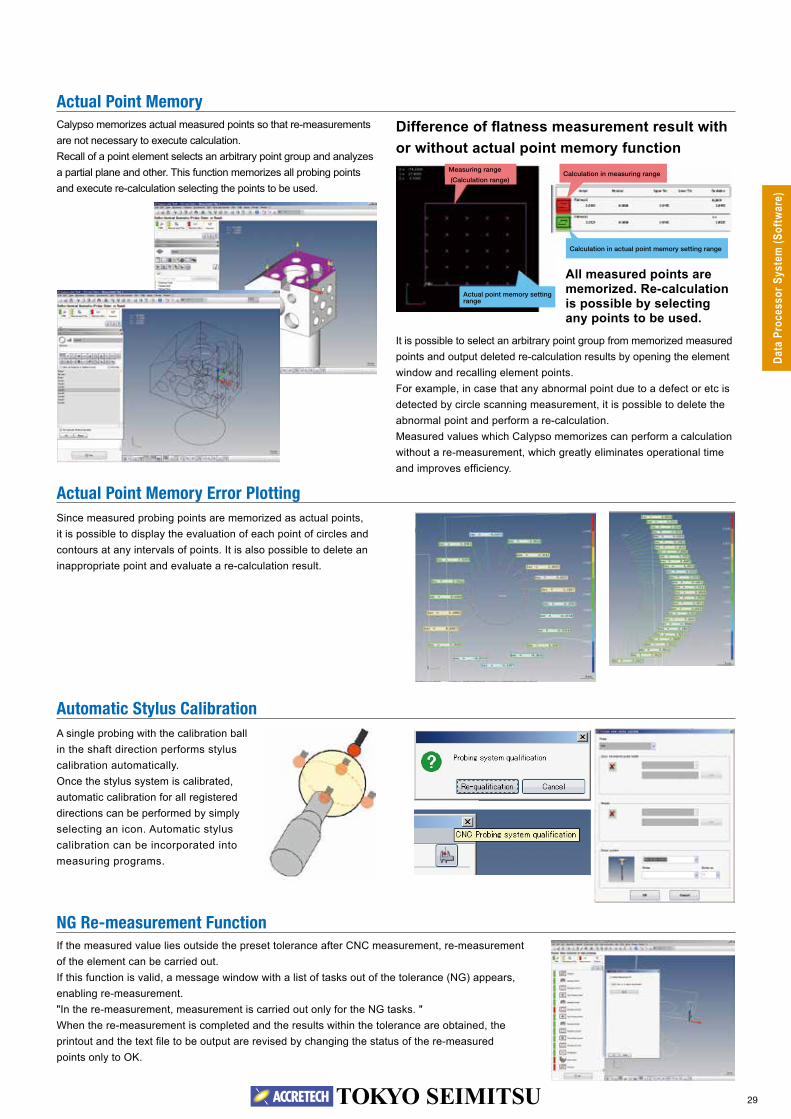
Actual Point Memory Error PlottingSince measured probing points are memorized as actual points, it is possible to display the evaluation of each point of circles and contours at any intervals of points. It is also possible to delete an inappropriate point and evaluate a re-calculation result .
Actual Point MemoryCalypso memorizes actual measured points so that re-measurements are not necessary to execute calculation.Recall of a point element selects an arbitrary point group and analyzes a partial plane and other. This function memorizes all probing points and execute re-calculation selecting the points to be used.
Difference of flatness measurement result with or without actual point memory function
All measured points are memorized. Re-calculation is possible by selecting any points to be used.
It is possible to select an arbitrary point group from memorized measured points and output deleted re-calculation results by opening the element window and recalling element points .For example, in case that any abnormal point due to a defect or etc is detected by circle scanning measurement, it is possible to delete the abnormal point and perform a re-calculation.Measured values which Calypso memorizes can perform a calculation without a re-measurement, which greatly eliminates operational time and improves efficiency.
Automatic Stylus Calibration
NG Re-measurement Function
A single probing with the calibration ball in the shaft direction performs stylus calibration automatically .Once the stylus system is calibrated, automatic calibration for all registered directions can be performed by simply selecting an icon . Automatic stylus calibration can be incorporated into measuring programs .
If the measured value lies outside the preset tolerance after CNC measurement, re-measurement of the element can be carried out. If this function is valid, a message window with a list of tasks out of the tolerance (NG) appears, enabling re-measurement . "In the re-measurement, measurement is carried out only for the NG tasks. "When the re-measurement is completed and the results within the tolerance are obtained, the printout and the text file to be output are revised by changing the status of the re-measured points only to OK.
Measuring range
(Calculation range)
Actual point memory setting range
Calculation in actual point memory setting range
Calculation in measuring range
Data
Pro
cess
or S
yste
m (S
oftw
are)

30
Diverse Edit FunctionsCalypso powerfully assists such operations as (1) Completing a regular part program by editing a teaching program created based on provisional measurement (2) Editing a complete program to register it as another program and (3) Reviewing the measurement items and measurement sequence after creation. Measurement sequence can be changed simply by moving the element icons . It has an unparalleled advanced algorithm that can be found easy as you get accustomed to using it.
● Measurement plan editor elementIn Calypso, CNC part program is referred to as measurement plan. Various factors of evaluation method, such as out-of-range measurement points of measured elements (measurement items), existence and type of filter can be collectively specified retrospectively .
● Mirror image functionFor measurement of left and right symmetrical components for auto parts, etc., mirror image of a part program on one side can be created and used as a program for the other side .
● Editing of measuring conditionsConditions of each element in a created measurement plan can be easily edited.• Changing the measurement point .• Change from point measuring to scanning measuring.• Changing specified height, position, auxiliary refuge surface, dimensions and tolerance
and element name .• Addition and deletion of measurement items.• Rearrangement of element icons that have been created.• Paint brush copy: Various measuring conditions and evaluation items configured for
the measurement of one element can be collectively copied and registered for another element (property).
プププププププププププ
Interchange of IconsFor example, once an analysis item “Circle 1” is newly added, the roundness measurement item is added to the end of all measurement characteristics . However, this makes the measurement program unclear which circle of a workpiece to be measured .To make the measurement program clearer and easier, characteristics of the same elements should be put together.Just by the select of a characteristic to be moved and drag-and-drop to anywhere, you can move an item and create a better measurement program that anyone can understand .
An order of measurement items can be changed easily . It helps to create an easier-to-understand measurement program .
Calypso Macro FunctionThis function enables configuration of a number of “small” measurement plans within a “large” measurement plan .
● Benefits of Calypso macro function• Able to create measurement plans of a plurality of repetitive
parts easily• Able to combine part-wise measurement plans easily (Utilization Example)
Combine Plan A with existing measurement plans B and C, using the macro function.
“Measurement Plan C” for measurement of side surface
“Measurement Plan B” for measurement of front surface
“Measurement Plan A” for measurement of top surface
Measurement plan editor window
Property window
31
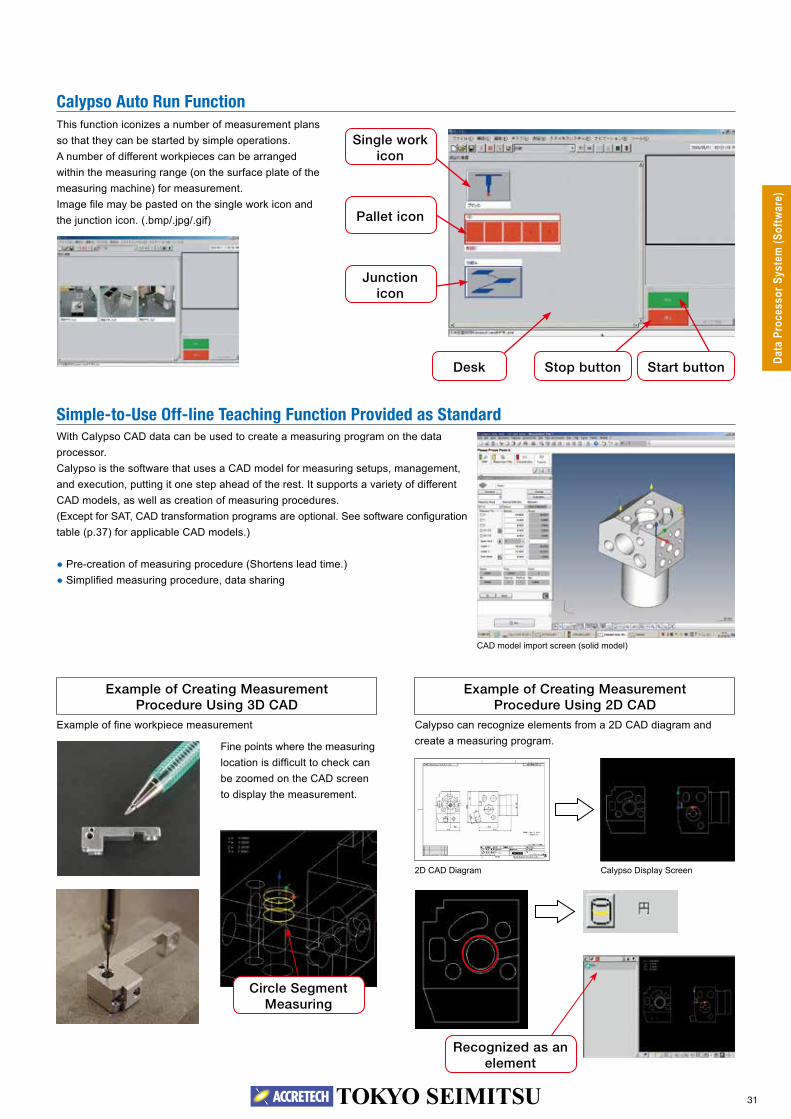
Simple-to-Use Off-Iine Teaching Function Provided as StandardWith Calypso CAD data can be used to create a measuring program on the data processor .Calypso is the software that uses a CAD model for measuring setups, management, and execution, putting it one step ahead of the rest. It supports a variety of different CAD models, as well as creation of measuring procedures. (Except for SAT, CAD transformation programs are optional. See software configuration table (p.37) for applicable CAD models.)
● Pre-creation of measuring procedure (Shortens lead time.) ● Simplified measuring procedure, data sharing
Example of Creating Measurement Procedure Using 3D CAD
Example of Creating Measurement Procedure Using 2D CAD
2D CAD Diagram Calypso Display Screen
Example of fine workpiece measurement Calypso can recognize elements from a 2D CAD diagram and create a measuring program .Fine points where the measuring
location is difficult to check can be zoomed on the CAD screen to display the measurement .
Calypso Auto Run FunctionThis function iconizes a number of measurement plans so that they can be started by simple operations .A number of different workpieces can be arranged within the measuring range (on the surface plate of the measuring machine) for measurement.Image file may be pasted on the single work icon and the junction icon. (.bmp/.jpg/.gif)
CAD model import screen (solid model)
Single work icon
Pallet icon
Junction icon
Desk Start buttonStop button
Circle Segment Measuring
Recognized as an element
Data
Pro
cess
or S
yste
m (S
oftw
are)
32
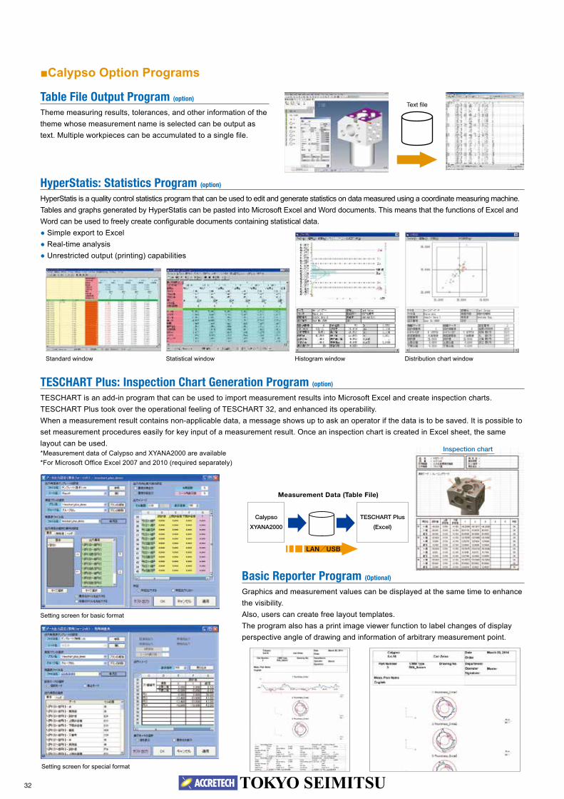
TESCHART Plus: Inspection Chart Generation Program (option)
TESCHART is an add-in program that can be used to import measurement results into Microsoft Excel and create inspection charts. TESCHART Plus took over the operational feeling of TESCHART 32, and enhanced its operability. When a measurement result contains non-applicable data, a message shows up to ask an operator if the data is to be saved. It is possible to set measurement procedures easily for key input of a measurement result. Once an inspection chart is created in Excel sheet, the same layout can be used .*Measurement data of Calypso and XYANA2000 are available *For Microsoft Office Excel 2007 and 2010 (required separately)
Basic Reporter Program (Optional)
Graphics and measurement values can be displayed at the same time to enhance the visibility .Also, users can create free layout templates.The program also has a print image viewer function to label changes of display perspective angle of drawing and information of arbitrary measurement point.
Table File Output Program (option)
Theme measuring results, tolerances, and other information of the theme whose measurement name is selected can be output as text. Multiple workpieces can be accumulated to a single file.
■Calypso Option Programs
Text file
Standard window Statistical window Histogram window Distribution chart window
Measurement Data (Table File)
Calypso
XYANA2000
TESCHART Plus
(Excel)
LAN/USB
Setting screen for basic format
Setting screen for special format
HyperStatis: Statistics Program (option)
HyperStatis is a quality control statistics program that can be used to edit and generate statistics on data measured using a coordinate measuring machine . Tables and graphs generated by HyperStatis can be pasted into Microsoft Excel and Word documents. This means that the functions of Excel and Word can be used to freely create configurable documents containing statistical data.
● Simple export to Excel ● Real-time analysis ● Unrestricted output (printing) capabilities
Inspection chart

33
Stylus Simulation (option)
This program provides on-screen simulation of an offline teaching CNC program. It is possible to simu-late and check for path interference visually.
Pipe Evaluation Function (option)
Pipe profiles are defined by intricately jointed cylindrical elements. This function calculates bent and twisted angles and intersection points of profiles. CAD data and manual input of values or measurement of master parts can define pipe profiles.
Hole Pattern Best Fit (option)
This function rotates or offsets the hole pattern in true position calculation to perform best fit.
PCM (Parameter Coded Measurement) (option)
This option produces an original message window before or after execution of a CNC measuring plan, and lets the operator configure detailed settings for the next action based on measurement results. When forms are identical, except for certain measured lengths or measured diameters, variables can be used for the reference values so multiple workpieces can be measured using the same part program . Parameter-Coded Measurement makes it possible to create highly refined original programs because the measuring path and other measuring machine movements can be controlled as required . Programs are text-based, so they can be incorporated into Calypso part programs, which makes Parameter-Coded Measurement a powerful CNC support tool.
DMIS Compatible System (option)
The ZVI interface is a function that converts measuring programs and commands created by a commercially available offline teaching system, and performs measuring operations. DMIS import is a function that imports measuring programs created in DMIS language and converts them to Calypso measuring programs . DMIS result output is a function that exports Calypso measuring results to a DMIS format file.*DMIS (Dimensional Measuring Interface Standard): Common measuring program language
List Calibration (option)
Rotation angles to be used can be pre-registered in a list for automatic calibration of the items included in the list .
EDM Module (option)
This electric discharge machine offline setup option provides evalu-ation of workpiece and electrode positions based on a master palette and other references.
Display of CMM and simulation of PH10M head and workpiece
Free Form Curved-Surface Evaluation (option)
Errors of actual measured value and nominal value are displayed as colored dots (standard function). Operators can check errors of each actual measured value for flatness, roundness and cylindricity evaluations visually, and recognize the concavity and convexity of a flat surface at a glance .Addition of optional Free Form function allows free form evaluations.
Twisted angleDa
ta P
roce
ssor
Sys
tem
(Sof
twar
e)

34
Cylindrical Cam Measurement Cylindrical cam measurement is available using a rotary table . Cam is measured at a constant radius on the center of rotation axis.The center line and groove width of the cam are evaluated. When a rotary tale is used, scanning mea-surements enable evaluations . (Standard function for Curve)
Form Data ASCII Input/Output Program (option)
ASCII fi le point data is imported as design value points of 2-dimensional curve element . Measurement results is saved in an ASCII fi le as form measurement results. Measurement results of form measurement program can be evaluated using contour anal-ysis software functions (ACCTee and TiMS).
Blade Pro: Turbine Blade Evaluation Program (option)
There are a number of different parameters and analytical methods used for controlling the quality of turbine blades.Blade Pro is the specialized software for turbine blades evaluations .Blade Pro imports nominal values and actual measured value data and performs turbine blade evaluation.
Multiple fi gures and text elements can be mixed into a single document. All documents can be confi gured with different orientations and paper sizes.All text and fi gures are freely movable, and rotate and move operations are supported .
IGES/DXF-ASCII Conversion Program (option)
This program can convert IGES or DXF data to an ASCII fi le that is used as 2-dimension form evaluation design data, and convert actual measured data to IGES or DXF data .
Expanded Plot (option)
Normally multiple forms measured on the same plane of a single workpiece are displayed and printed in one form at a time .This option makes it possible to display and print multiple forms together in a form, including their position information.
■Calypso-CURVE: Curve Form Measuring Program (option)Calypso-CURVE is a Calypso option program for measuring 2-dimensionalcross section forms of a workpiece. This program allows measuring of known/unknown contours and forms, and totaling of design values. Measurement data is output as design values and normal direction error. When there is a deviation in the error due to shifting of the standard, 2D best fi t eliminates any inappropriate error in the measurement standard so the form can be evaluated.
[Functions] · Unknown form digitizing measurement · Known form reference value comparison measurement · Design value defi nition (creation function) –Design value data generation by digitizing measurement –Design value generation by direct input –Design value data related operations Design point editing, the best fi t for the actual measurement
value for design. –Reference curve defi nition · Measuring result list output · List output of form errors in comparison measurement · Graphic output of form errors in comparison measurement · Straight line developed graphic output of form errors in comparison measurement · 2-dimensional best fi t calculations based on form error results in comparison measurement · Alignment correction based on best fi t calculations
* Output example of cylindrical cam evaluation (A form plot option is required to obtained the output above.)
Analysis result
Coordinate Measuring Machine Calypso-CURVE