coordinate arbitrary magnetic field control system for
TRANSCRIPT

Coordinate arbitrary Magnetic Field Control System for
driving an Externally Powered and Geared Endoscopy
Capsule Motor
Gavin Kane1, Henrik Keller1,2, Jorg Raczkowsky1, Heinz Worn1
1Karlsruhe Institute for Technology, Karlsruhe, Germany2Siemens Healthcare, Erlangen, Germany
Corresponding Author Email: gavin j [email protected]
November 17, 2011
AbstractMagnetically Guided Capsule Endoscopy isa recent advancement in Capsule Endoscopy.Precise control of the capsule is however usu-ally limited to manual steering. The work pre-sented here demonstrates the embedding of a3D magnetic sensor for establishing a coordi-nate arbitrary Magnetic Field Control Systemfor use in driving a capsule motor system ex-ternally. A concept and prototype for a motorand gearing system is also provided togetherwith simulation and test data from the sensor,model and prototype.
1 Introduction
Capsule Endoscopy (CE) is continually demonstratingthat it has significant advantages[[1][2][3][4]] over alter-nate available techniques for detecting problems such assources of bleeding in the gastrointestinal (GI) tract, butit still does not achieve 100% detection. Until recentlythe capsule was not controllable and moved passivelythrough the GI tract recording images. Ishiyama andcolleagues proposed the use of a magnetic field in driv-ing the capsule endoscope. [5] thus allowing doctors theability to better visualise any suspicious lesions.
Magnetically Guided Capsule Endoscopy (MGCE) isa recent advancement in Capsule Endoscopy. It offersthe same advantages as normal capsule endoscopy as aminimal invasive procedure compared to conventionalendoscopy, but extends the benefits by providing anability for the doctor to control the capsule as the cap-sule moves through the stomach. This means a doctor isnot required to search through large quantities of data
recordings, but can direct the capsule and concentratethe diagnostic procedure and image collection where theproblem is. The results of the first clinical study havebeen published here [4].
As previously mentioned, the system is presently lim-ited to the stomach, where an amount of water drunkby the patient, allows a capsule to swim easily with rel-atively low magnetic fields. These low magnetic fieldsand gradients, with the resultingly low forces restrict theconcept from being employed further along the gastroin-testinal tract. Here more complex movement conceptsare required.
There are a number of projects developing robotscapable of such movement for the small and large in-testines. Examples of such robots are the 12-legged cap-sule with slot-follower/lead screw mechanism by KIST(South Korea), Johns Hopkins University (USA) andthe CRIM Lab (Italy) [6] or the Paddling based Mi-crorobot by KIST (South Korea) [7]. These systemsshow the capability of moving through the GI tract,but are generally hampered by the requirement to carrynot only the motors for controlling such movement, butalso the batteries needed to drive these motors. An al-terante concept proposed by the ETH (Switzerland) in2008 was for a swimming Capsule Endoscope operatinginside an MRI using the static and RF magnetic fieldsfor propulsion [8].
In the work by Wang et al. [9] they discuss the use ofan MGCE system built with three orthogonal circularcoil pairs for pushing and pulling endoscopic capsules.However, the work is limited to require the position andorientation of the magnetic seed. The work by Hong etal. [10] does make an estimation of the position and an-gle, but with errors up to 15 degrees, and no closed loop
1
control, they only test their model in a fixed frequencymodulated field.
This paper presents a method for using the MGCEsystem to control a capsule with a multitude of possi-ble movement mechanisms. Without implying the useof one specific movement or traction concept, this workfocuses on the development of this control system neces-sary for adapting any possible drive system. The com-plexity and requirements for externally controlling a mo-tor, possibly including multiple geared drive shafts isoutlined in section 2. Section 3 outlines the construc-tion of a prototype geared system, the control algo-rithm, the simulation environment, and description ofthe test MGCE System. Section 4 provides the simu-lation and experimentation results including their com-parison. Section 5 discusses the implications of the re-sults, and outlines the future work for pushing the ca-pability forward.
2 Problem Background
2.1 MGCE Systems
An MGCE system includes a series of coils surround-ing a patient table, and capable of generating dynamicmagnetic fields in three-dimensional space, nearly ho-mogenous over an area approximating that of the humanstomach. The vector of this field can be controlled interms of direction and of magnitude. The system oper-ates at significantly lower field strengths compared withthat of an MRI. The MGCE system is also capable ofgenerating a gradient of this field in a second arbitrarilychosen vector.
2.2 System Constraints and Considera-tions
As a comparison between the generated B-Field and gra-dient, the B-Field is considerably stronger than the gra-dient and more influencial. To magnetic items placedwithin the system, the implication is that a strongtorque can be applied to the magnet, but only very lim-ited force. The engineering implication of this statementis that directly pushing a push-rod or other drive item isnot effective, but the conversion of the torques throughlevers and threads, while requiring more space, can yieldsignificantly larger gains.
The second constraint of using an MGCE system forconveying mechanical energy to an internal mechanicalcomponent, is that only a single magnetic field can begenerated that influences the complete capsule and allmagnetic items inside the capsule. It is not possible tohave multiple items activated seperately without addi-tional complexities. E.g. instead of using permanent
Capsule DriveRotation andaxis of motion
MagneticField
Rotation
Timet=0
Timet=1
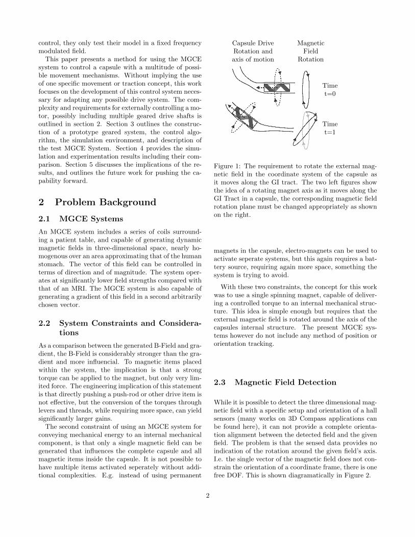
Figure 1: The requirement to rotate the external mag-netic field in the coordinate system of the capsule asit moves along the GI tract. The two left figures showthe idea of a rotating magnet axis as it moves along theGI Tract in a capsule, the corresponding magnetic fieldrotation plane must be changed appropriately as shownon the right.
magnets in the capsule, electro-magnets can be used toactivate seperate systems, but this again requires a bat-tery source, requiring again more space, something thesystem is trying to avoid.
With these two constraints, the concept for this workwas to use a single spinning magnet, capable of deliver-ing a controlled torque to an internal mechanical struc-ture. This idea is simple enough but requires that theexternal magnetic field is rotated around the axis of thecapsules internal structure. The present MGCE sys-tems however do not include any method of position ororientation tracking.
2.3 Magnetic Field Detection
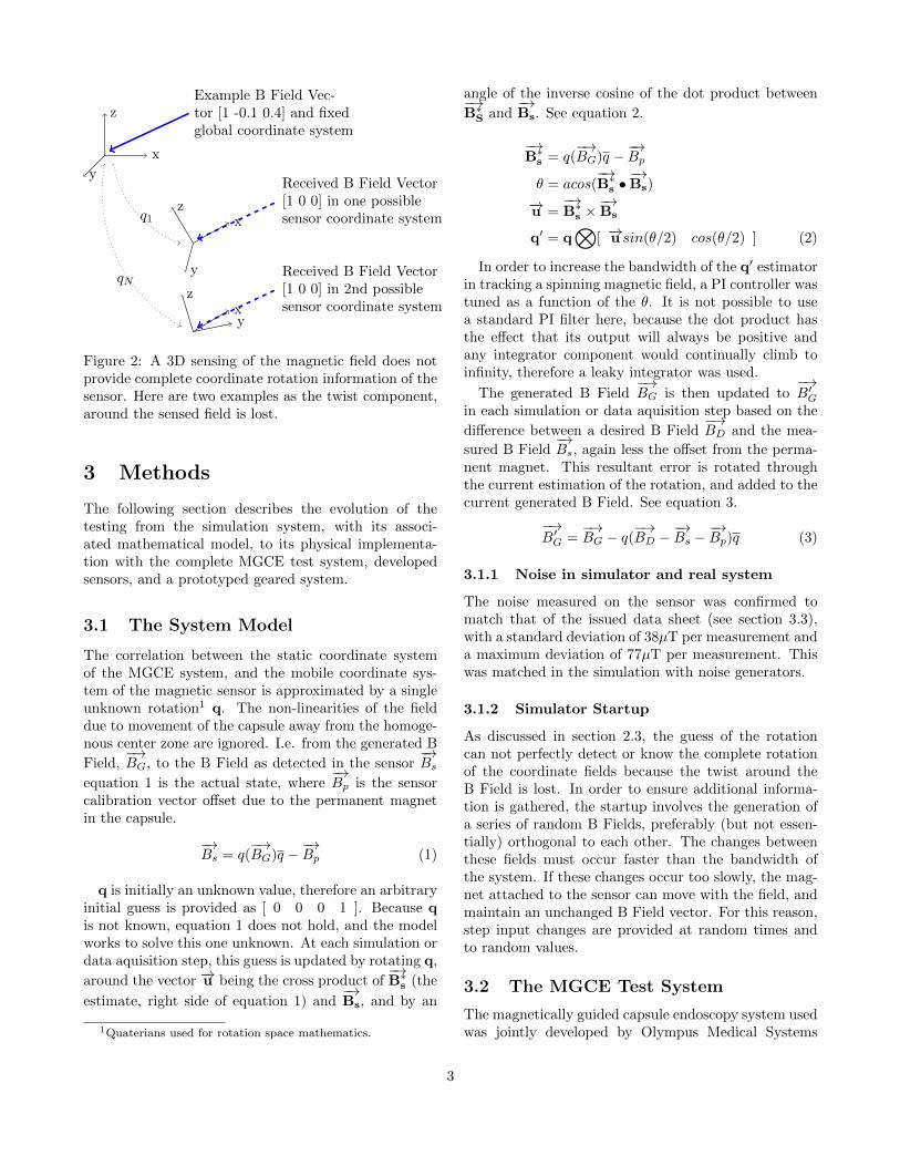
While it is possible to detect the three dimensional mag-netic field with a specific setup and orientation of a hallsensors (many works on 3D Compass applications canbe found here), it can not provide a complete orienta-tion alignment between the detected field and the givenfield. The problem is that the sensed data provides noindication of the rotation around the given field’s axis.I.e. the single vector of the magnetic field does not con-strain the orientation of a coordinate frame, there is onefree DOF. This is shown diagramatically in Figure 2.
2
x
z
y
Example B Field Vec-tor [1 -0.1 0.4] and fixedglobal coordinate system
xz
y
Received B Field Vector[1 0 0] in one possiblesensor coordinate system
xz
y
Received B Field Vector[1 0 0] in 2nd possiblesensor coordinate system
q1
qN
Figure 2: A 3D sensing of the magnetic field does notprovide complete coordinate rotation information of thesensor. Here are two examples as the twist component,around the sensed field is lost.
3 Methods
The following section describes the evolution of thetesting from the simulation system, with its associ-ated mathematical model, to its physical implementa-tion with the complete MGCE test system, developedsensors, and a prototyped geared system.
3.1 The System Model
The correlation between the static coordinate systemof the MGCE system, and the mobile coordinate sys-tem of the magnetic sensor is approximated by a singleunknown rotation1 q. The non-linearities of the fielddue to movement of the capsule away from the homoge-nous center zone are ignored. I.e. from the generated B
Field,−→BG, to the B Field as detected in the sensor
−→Bs
equation 1 is the actual state, where−→Bp is the sensor
calibration vector offset due to the permanent magnetin the capsule.
−→Bs = q(
−→BG)q −
−→Bp (1)
q is initially an unknown value, therefore an arbitraryinitial guess is provided as [ 0 0 0 1 ]. Because qis not known, equation 1 does not hold, and the modelworks to solve this one unknown. At each simulation ordata aquisition step, this guess is updated by rotating q,
around the vector −→u being the cross product of−→B∗s (the
estimate, right side of equation 1) and−→Bs, and by an
1Quaterians used for rotation space mathematics.
angle of the inverse cosine of the dot product between−→B∗S and
−→Bs. See equation 2.
−→B∗s = q(
−→BG)q −
−→Bp
θ = acos(−→B∗s •
−→Bs)
−→u =−→B∗s ×
−→Bs
q′ = q⊗
[ −→u sin(θ/2) cos(θ/2) ] (2)
In order to increase the bandwidth of the q′ estimatorin tracking a spinning magnetic field, a PI controller wastuned as a function of the θ. It is not possible to usea standard PI filter here, because the dot product hasthe effect that its output will always be positive andany integrator component would continually climb toinfinity, therefore a leaky integrator was used.
The generated B Field−→BG is then updated to
−→B′G
in each simulation or data aquisition step based on the
difference between a desired B Field−→BD and the mea-
sured B Field−→Bs, again less the offset from the perma-
nent magnet. This resultant error is rotated throughthe current estimation of the rotation, and added to thecurrent generated B Field. See equation 3.
−→B′G =
−→BG − q(
−→BD −
−→Bs −
−→Bp)q (3)
3.1.1 Noise in simulator and real system
The noise measured on the sensor was confirmed tomatch that of the issued data sheet (see section 3.3),with a standard deviation of 38µT per measurement anda maximum deviation of 77µT per measurement. Thiswas matched in the simulation with noise generators.
3.1.2 Simulator Startup
As discussed in section 2.3, the guess of the rotationcan not perfectly detect or know the complete rotationof the coordinate fields because the twist around theB Field is lost. In order to ensure additional informa-tion is gathered, the startup involves the generation ofa series of random B Fields, preferably (but not essen-tially) orthogonal to each other. The changes betweenthese fields must occur faster than the bandwidth ofthe system. If these changes occur too slowly, the mag-net attached to the sensor can move with the field, andmaintain an unchanged B Field vector. For this reason,step input changes are provided at random times andto random values.
3.2 The MGCE Test System
The magnetically guided capsule endoscopy system usedwas jointly developed by Olympus Medical Systems
3
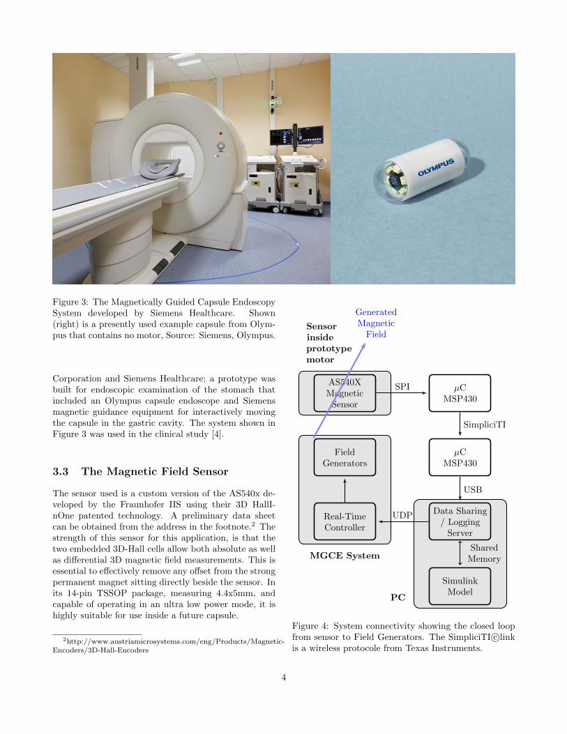
Figure 3: The Magnetically Guided Capsule EndoscopySystem developed by Siemens Healthcare. Shown(right) is a presently used example capsule from Olym-pus that contains no motor, Source: Siemens, Olympus.
Corporation and Siemens Healthcare; a prototype wasbuilt for endoscopic examination of the stomach thatincluded an Olympus capsule endoscope and Siemensmagnetic guidance equipment for interactively movingthe capsule in the gastric cavity. The system shown inFigure 3 was used in the clinical study [4].
3.3 The Magnetic Field Sensor
The sensor used is a custom version of the AS540x de-veloped by the Fraunhofer IIS using their 3D HallI-nOne patented technology. A preliminary data sheetcan be obtained from the address in the footnote.2 Thestrength of this sensor for this application, is that thetwo embedded 3D-Hall cells allow both absolute as wellas differential 3D magnetic field measurements. This isessential to effectively remove any offset from the strongpermanent magnet sitting directly beside the sensor. Inits 14-pin TSSOP package, measuring 4.4x5mm, andcapable of operating in an ultra low power mode, it ishighly suitable for use inside a future capsule.
2http://www.austriamicrosystems.com/eng/Products/Magnetic-Encoders/3D-Hall-Encoders
MGCE System
PC
Sensorinsideprototypemotor
AS540XMagnetic
Sensor
µCMSP430
µCMSP430
Data Sharing/ Logging
Server
SimulinkModel
Real-TimeController
FieldGenerators
GeneratedMagnetic
Field
SPI
SimpliciTI
USB
SharedMemory
UDP
Figure 4: System connectivity showing the closed loopfrom sensor to Field Generators. The SimpliciTI c©linkis a wireless protocole from Texas Instruments.
4

Gear aroundsmaller discmagnet
Gear fixed to frontof cylinder magnet
2nd Gear fixedto drive shaft
Magnetic Sensor(fixed inside magnet)
Chamber allowing free rotation and sliding of magnet
Figure 5: Top. Photo of the first prototype with an en-gaged / disengaged (or clutched) gearing option. Thegreen cylinder magnet can slide forward against the 2ndGear component while rotating, engaging the gear, orslide away from the 2nd component, disengaging thegearing. Below. Concept Images of a second prototypewith multiple drive axis. Here a single ring magnet (sil-ver) is attached to one gear (green), together they canslide back and forth while spinning engaging the threedifferent drive axis (cyan).
3.4 Test System Setup
Using the MGCE shown in Figure 3 the sensor andmodel were interfaced as shown in Figure 4. The sensoraquisition rate, as per the system update rate were bothset at 100 Hz.
3.5 Geared Motor Prototype
From the earliest works discussed in the introduction,the most suitable types of movement for extending thecapability of the MGCE past the stomach to furthersections of the GI Tract are those mentioned in [6][7].These systems currently have the limitation that theyrequire motors and thus larger batteries to be carriedinside the capsule. In order to use the external fieldcontrol of the MGCE, it was necessary to develop amethod for controlling a number of different drive com-ponents from only one magnet. This was achieved byplacing the magnet with fixated sensor in a tube sec-tion, where the magnet is still able to move a few mil-
limetres forwards and backwards. This sliding could becontrolled by the external field gradient, requiring onlyvery slight force to move the magnet from one end of thetube to the other. This effect was used as the controlof the gearing. On one side of the magnet a saw toothgear was fixed. This gearing would be able to drive onemechanical component, and works similar to a clutchmechanism (On or Off). The geared system is showndisassembled in Figure 5. By adding additional gearingsections on the opposite side of the magnet later, ad-ditional mechanisms can be driven. Such a concept isshown in the lower images of Figure 5. A significant ad-vantage of such a motor concept is the torque to volumeratio. This motor requires the capsule to include no in-ternal electromagnetic coils, no controlling electronics,and importantly no battery power is needed for the mo-tor, thus increasing the operating time by dedicating allthe battery power to the camera and wireless transmis-sion. The torques are also considerably large in com-parison with other capsule motors used as discussed inthe introduction because a single large ring magnet canbe used with a radius only marginally smaller than thecomplete capsule.
3.6 Torque Control Drive Mode
In the work by Wang et al. [9] they attempt to tracka sensor while rotating the magnet fields. Outlined inFigure 1 was the idea that to achieve continual efficientcontrol along an arbitrary route, the field must be ro-tated directly around the rotational axis of the magnet.A more elegant solution here exists, whereby the mag-netic field is moved in a closed loop system, slightly offaxis from the magnet. In this fashion, the magnet is heldstable by the strong field holding it in position, and aset amount of torque is provided by the off axis natureof the field. As the magnet turns due to the torque, thefield is again moved off axis from the new position. Inthis concept the same movement is achieved, but themodel reveals two large advantages. Firstly, a torquefeedback is achieved by how quickly the motor acceller-ates. Secondly, a more stable running mode is achievedwith the system able to be optimised to 100% of thepossible torque of the magnet.
4 Results
4.1 Drift in Simulation
The first set of simulations were designed to verify thatthe model worked as expected, and in order to tune thecontrol parameters. The first results shown in Figure6 demonstrate the expected result when a constant BField force is maintained on the system. After initial
5

alignment of the coordinate systems, drift continues tooccur around the axis of the given B Field, and aftera time, the correlation (defined as the dot product ofthe two quaterian vectors) between the two coordinatesystems decreases.
0 2 4 6 8 10 12 14 16
Time (min)
0.75
0.5
1.0
Cor
rela
tion
Fac
tor
Figure 6: Log of the correlation between the estimatedrotations vector and the actual rotations vector in thesimulated system. 1.0 indicates complete correlation.The drift about the B Field vector is seen to increasesignificantly from approximately 9min.
4.2 Drift Avoidance, Correlation Im-provement
In order to improve the rotation estimate, the systemwas tested with continually changing B Fields, thusproviding continually more information about the ad-ditional axis. Figure 7 shows how this concept immedi-ately provides more information with the improvementof the correlation factor. After only two changes, thecorrelation is increased to over 0.996, this equates to anangular discrepancy of < 2◦. The poor correlation inthe first 0.8 secs is due to the complete absence of anydesired B Field.
4.3 Simulation / System Comparison
The model from the Simulation was applied directly tothe complete MGCE with only modification to the PDand PI control values. In this setting, the gains were alllowered, to reduce any sudden movements of the mag-nets in a poorly orientated or oscillating magnetic field.Figure 8 shows two example startups of the system. Inthese tests the magnetic sensor was placed inside theMGCE system at a random orientation. The locationwas approximately near the middle. From the datathere are two important points to note, firstly that themodel appears to work and the system is able to gener-ate the desired magnetic field, in the coordinate systemof the sensor. Secondly, the magnetic field approachesthe desired field strengths, well before the orientation
Measured / Desired B Field (X Axis)
Measured / Desired B Field (Y Axis)
Measured / Desired B Field (Z Axis)
(For all future graphs of Magnetic Fields)
0 0.5 1 1.5 2 2.5 3
Time (s)
10
7.5
5
2.5
0
-10
-7.5
-5
-2.5
Mag
net
icF
ield
(mT
)
0.75
0.5
0.25
0.0
1.0
Cor
rela
tion
Fac
tor
0 0.5 1 1.5 2 2.5 3Time (s)
Figure 7: Simulated System startup showing continualincrease in correlation between estimated and real ro-tation, associated with decrease in noise in B Field atsensor. Increases in correlation can be seen associatedwith a change in the B Field, i.e. information providedin additional rotation components. As expected, a poorcorrelation occurs in the first 0.8sec is due to the com-plete absence of any desired B Field.
6
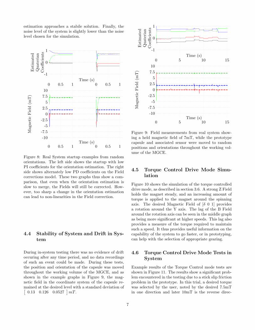
estimation approaches a stabile solution. Finally, thenoise level of the system is slightly lower than the noiselevel chosen for the simulation.
0 0.5 1 0 0.5 1Time (s)
1
0
-1
Est
imate
dQ
uate
rian
Coeffi
cien
ts
0 0.5 1 0 0.5 1Time (s)
10
7.5
5
2.5
0
-10
-7.5
-5
-2.5
Mag
net
icF
ield
(mT
)
Figure 8: Real System startup examples from randomorientations. The left side shows the startup with lowPI coefficients for the orientation estimation. The rightside shows alternately low PD coefficients on the Fieldcorrections model. These two graphs thus show a com-parison, that even when the orientation estimation isslow to merge, the Fields will still be corrected. How-ever, too sharp a change in the orientation estimationcan lead to non-linearities in the Field correction.
4.4 Stability of System and Drift in Sys-tem
During in-system testing there was no evidence of driftoccuring after any time period, and no data recordingsof such an event could be made. During these tests,the position and orientation of the capsule was movedthroughout the working volume of the MGCE, and asshown in the example graphs in Figure 9, the mag-netic field in the coordinate system of the capsule re-mained at the desired level with a standard deviation of[
0.13 0.126 0.0527]mT .
0 5 10 15Time (s)
1
0
-1
Est
imate
dQ
uat
eria
nC
oeffi
cien
ts
0 5 10 15Time (s)
10
7.5
5
2.5
0
-10
-7.5
-5
-2.5
Mag
net
icF
ield
(mT
)Figure 9: Field measurements from real system show-ing a held magnetic field of 7mT, while the prototypecapsule and associated sensor were moved to randompositions and orientations throughout the working vol-ume of the MGCE.
4.5 Torque Control Drive Mode Simu-lation
Figure 10 shows the simulation of the torque controlleddrive mode, as described in section 3.6. A strong Z Fieldholds the magnet steady, and an increasing amount oftorque is applied to the magnet around the spinningaxis. The desired Magnetic Field of [δ 0 1] providesa rotation around the Y axis. The lag of the B Fieldaround the rotation axis can be seen in the middle graphas being more significant at higher speeds. This lag alsoprovides a measure of the torque required to maintainsuch a speed. It thus provides useful information on thecapability of the system to go faster, or in prototyping,can help with the selection of appropriate gearing.
4.6 Torque Control Drive Mode Tests inSystem
Example results of the Torque Control mode tests areshown in Figure 11. The results show a significant prob-lem encountered in the testing due to a stick slip frictionproblem in the prototype. In this trial, a desired torquewas selected by the user, noted by the desired 7.5mTin one direction and later 10mT is the reverse direc-
7

0 0.5 1 1.5 2 2.5 3Time (s)
1
0
-1
Est
imate
dQ
uate
rian
Coeffi
cien
ts
0 0.5 1 1.5 2 2.5 3Time (s)
10
7.5
5
2.5
0
-10
-7.5
-5
-2.5
Magn
etic
Fie
ld(m
T)
Figure 10: Simulation System driving a rotating mag-net, with the speed increased at 0.75s, 1.45s, 2.4s. Thedesired Magnetic Field of [δ 0 1] provides a rotationaround the Y axis.
tion. The field rotated around the axis until the firstslip occured with sudden acceleration. Due to this sud-den acceleration, the sensor moves, and the field takesa set period of time to realign, building up the torquein the process until the next slip occurs. This was seento occur in both directions of rotation.
4.7 Homogenity of System
The MGCE system had been previously calibrated tohave a homogenous field in the space in which a patientstomach would lie during a diagnostic procedure. As aside effect of the magnetic sensor inclusion in a closedloop system this working volume can be significantlyincreased without a need for further system calibration.Figure 12.a and b show the measurements made of thesystem with and without the above described model. Itshows over a space of 80cm the standard field of theMGCE changes over 2.5mT, this is 50% of the desiredvalue. Additionally, the orientation of the field changeswings by over 4◦ .
When the closed loop model was applied, the fieldwas stable and consistent for over 650mm. The limita-tion of the field then occurs due to a software enforcedlimiting of the field. In the model used in this test, eachindividual field component was limited to 1.5 times the
0 5 10 15Time (s)
1
0
-1
Est
imate
dQ
uat
eria
nC
oeffi
cien
ts
0 5 10 15Time (s)
10
7.5
5
2.5
0
-10
-7.5
-5
-2.5
Mag
net
icF
ield
(mT
)Figure 11: Real System measurements while driving arotating magnet forwards and backwards. The unsta-ble data is due to a stick slip problem of the magnetin its chamber leading to excessively high and suddenaccelerations.
magnitude of the overall desired field. This was to pre-vent any excessive currents and overheating should themodel become instabile. In future tests, this limitationis likely to be weakened or completely removed, with ahigh likelyhood of extending this working volume con-siderably more. It is important to note that while thisconstraint was software enforced, the direction of thevector was continually maintained even into the non-linear region.
5 Conclusion
This work has shown how effectively the capsule orien-tation can be determined through an embedded mag-netic sensor. These results show the stabile and fastoptimisation of the magnetic field into the capsules co-ordinate system, regardless of startup orientation. Thisoptimisation of the magnetic field also increases the ef-fective working volume of the MGCE system by over200%. The torque drive mode provides a stable andcontrollable method for powering a motor inside a fu-ture generation of endoscopy capsules. This externaldrive removes the requirement for additional batteriesinside the capsule.
Future work is aimed at including the gradient control
8

−200 0 200 400 600−6
−4
−2
0
mm placement of sensor in system
mT
read
ing
from
sen
sor
−200 0 200 400 600
0
2
4
mm placement of sensor in system
An
gu
lar
Err
or
from
nor
m(d
egre
es)
−200 0 200 400 600−6
−4
−2
0
mm placement of sensor in system
mT
read
ing
from
sen
sor
Figure 12: Field Homogenitiy Measurements of RealMGCE System, Figure 12.a are raw measurements ofthe field strength and vector with a desired setting of5mT in the Z Vector. Figure 12.b shows the angular er-ror of this field (normalised around its minimum). Fig-ure 12.c are raw measurements of the field strength witha desired setting of 5mT in the Z Vector with the closedloop correction turned on.
of the field in the model, this will be key to achievingfaster gear changes without loss of a stabil field at thecapsule’s location and in the appropriate orientation.
References
[1] S. L. Triester, J. A. Leighton, G. I. Leontiadis, D. E.Fleischer, A. K. Hara, R. I. Heigh, A. D. Shiff,and V. K. Sharma, “A meta-analysis of the yieldof capsule endoscopy compared to other diagnosticmodalities in patients with obscure gastrointestinalbleeding,” American Journal of Gastroenterology,vol. 100, pp. 2407–2418, 2005.
[2] M. Hadithi, G. D. N. Heine, M. A. Jacobs, A. A.v Bodegraven, and C. J. J. Mulder, “A prospec-tive study comparing video capsule endoscopy withdouble-balloon enteroscopy in patients with ob-scure gastrointestinal bleeding,” American Journalof Gastroenterology, vol. 101, pp. 52–57, 2006.
[3] E. Rondonotti, F. Villa, C. J. Mulder, M. A. Ja-cobs, and R. de Franchis, “Small bowel capsuleendoscopy in 2007: Indications, risks and limita-tions,” World Journal of Gastroenterology, vol. 13,pp. 6140–6149, 2007.
[4] J. Rey, H. Ogata, N. Hosoe, K. Ohtsuka, N. Ogata,K. Ikeda, H. Aihara, I. Pangtay, T. Hibi, S. Kudo,and H. Tajiri, “Feasibility of stomach explorationwith a guided capsule endoscope,” Endoscopy,vol. 42, No. 7, pp. 541–545, 2010.
[5] M. Sendoh and K. Ishiyama, “Fabrication of mag-netic actuator for use in a capsule endoscope,”IEEE Transactions on Magnetics, vol. 39, No. 5,pp. 3232–3234, 2003.
[6] P. Valdastri, I. R. J. Webster, C. Quaglia,M. Quirini, A. Menciassi, and P. Dario, “A newmechanism for mesoscale legged locomotion in com-pliant tubular environments,” IEEE Transactionson Robotics, vol. 25, No. 5, pp. 1047–1057, 2009.
[7] S. Park, H. Park, S. Park, C. Jee, J. Kim, andB. Kim, “Capsular locomotive microrobot for gas-trointestinal tract,” Proceedings of the 28th An-nual International Conference of the IEEE EMBS,pp. 2211–2214, 2006.
[8] G. Ksa, P. Jakab, F. Jlesz, and N. Hata, “Swim-ming capsule endoscope using static and rf mag-netic field of mri for propulsion,” IEEE Inter-national Conference on Robotics and Automation,pp. 2922–2927, 2008.
9

[9] X. Wang and M. Meng, “A magnetic stereo-actuation mechanism for active capsule endo-scope,” Proceedings of the 29th Annual Interna-tional Conference of the IEEE EMBS, pp. 2811–2814, 2007.
[10] M. K. Y. Hong and E. Lim, “Position and orienta-tion detection of capsule endoscopes in spiral mo-tion,” International Journal of Precision Engineer-ing and Manufacturing, vol. 11. No. 1, pp. 31–37,2010.
10