cooper bussmann products and technical support delivered worldwide · pdf file ·...
TRANSCRIPT

Reorder # ASL -2006
Cooper Bussmann Products AndTechnical Support Delivered Worldwide
Customer Assistance
Customer Satisfaction Team
The Cooper Bussmann Customer Satisfaction Team is availableto answers questions regarding Bussmann® products and services.
Contact should be made betweenMonday - Friday 7:30 a.m. – 5:30 p.m GMT.
The Customer Satisfaction Team can be reached via:
• Phone: 00 44 (0) 1509 882 600• Fax: 00 44 (0) 1509 882 786• E-mail: [email protected]
Application Engineering
Application Engineering assistance is available to all customers. The Application Engineering team is staffed by degreed electricalengineers and available by phone with technical and applicationsupport Monday - Friday 8.30am - 4.30pm GMT.
Application Engineering can be reached via:
• Phone: 00 44 (0) 1509 882 699• Fax: 00 44 (0) 1509 882 794• E-mail: [email protected]
Web Services
www.cooperbussmann.co.uk
The Cooper Bussmann website makes availablefree information and other resoures that include:
• Product Data Sheets for complete technical information on Busmann products
• Online catalogue for the latest United States and European catalogues
• Safety BASICS™ for the essentials of electrical safety
• Training Modules for increasing skill levels of customers and end users
• Fuse Cross Reference to find the correct Bussmann replacement for a competitive fuse
• Arc-Flash calculator to determine the incident energy level and flash protection boundry along with the recommendations the levelof Personal Protective Equipment (PPE)
Your Authorised Cooper Bussmann Distributor is:
Cooper Bussmann (UK) Ltd | Burton-on-the-Wolds | Leicestershire | LE12 5TH UK
Tel: 44 (0)1509 882 737 | Fax: 44 (0)1509 882 786Email: [email protected] | www.cooperbussmann.co.uk
Circuit Protection SolutionsAutomatic Sectionalising Link Catalogue

Cooper Bussmann are one of the world’s leading suppliers of fuses and fusible
protection systems. Provider of the world’s first truly global product line, each
product is backed by an efficient world-wide distribution network service and
unrivalled technical support. Cooper Bussmann circuit protection solutions
comply with major international standards: BS, IEC, DIN and UL.
Cooper Bussmann High Voltage fuses have absorbed and embodied the expertise and
experience of thirteen of the most prestigious manufacturers and are able to offer an
unbeatable range of products in terms of technical excellence, performance and quality.
Cooper Bussmann offer a wider range of High Voltage fuses than any other manufacturer
and types are available to meet most service applications. With over 50 years’
experience in design and manufacture, Cooper Bussmann have supplied fuselinks to
more than 90 countries world-wide.
Cooper Bussmann High Voltage fuses are extremely effective in preventing damage to
a system in the event of a fault, due to considerable limitation of let-through current in
DIN and British Standard designs to the latest IEC requirements.
Cooper Bussmann are pioneers in the development of Full Range High Voltage fuselinks
and is consequently the market leader in this field offering genuine full range
characteristics.
Cooper Bussmann’s team of specialist engineers play a leading role in international
standardisation of High Voltage fuses, offering a comprehensive service of advice, on
selection and applications.
With a continual commitment to meet our customers’ needs, with innovative, high quality
products with ISO 9002 ‘approved systems’, Cooper Bussmann are the suppliers choice
for High Voltage Circuit Protection Solutions.
WORLD-WIDE CIRCUIT PROTECTION SOLUTIONS
Automatic Sectionalising Link

Automatic Sectionalising Link
Table of ContentsPage
Contents / Introduction
Features 1
Construction 1-2
Operation 3-4
Application 5-10
Selection 11-16
Installation 17-18
Colour Coding Information 19-20
Ordering Information 21
Automatic Sectionalising Link

This booklet provides detailed information on the Cooper Bussmann AutomaticSectionalising Link (ASL) or Smart Link for use in distribution cut-outs.
ASL Contents/Information
Low cost retrofit option for spur line isolation in place of existing expulsion fuses
Available for up to 38kV overhead lines.
Pick-up current ratings from 15 to 320 Amps.
Enhanced lightning immunity perfomance.
1, 2 or 3 shot options available.
Electronic circuit fully encapsulated.
The Bussmann Automatic Sectionalising
Link (ASL), represents a significant
breakthrough in the field of medium voltage
overhead line distribution system protection,
offering considerable savings in operating
costs and minimising unnecessary interuptions
to customers.
Using the Bussmann ASL, an economical
system can be installed utilising most existing
explusion drop out fuse mounts in conjunction
with multishot circuit breakers or auto-
reclosers. Even where no expulsion fuse
mounts exist and these have to be provided,
significant benefits can still be achieved.
Major benefits in efficiency and performancesare achieved by:
• Reducing outages caused by transient no-damagefaults, especially due to lightning, which wouldotherwise cause unneccessary operation ofexpulsion fuse-links.
• Reducing unnecessary ‘call outs’ due to nuisancetransient faults.
• Sectionalising and isolating the network therebyreducing the number of customers disconnecteddue to permanent faults.
• Providing visual identification of a fault downstreamof the ASL and therefore allowing speedyrestoration of supply.
Statistics show that up to 90% of expulsion fuse-linkoperations on spur lines are in response to transientno-damage faults. The cost for each expulsion fuse-link replacement can be the same as the capital costof a complete fuse cut-out.The alternative approachof replacing expulsion fuse-links by solid links hasthe disadvantage that any permanent fault on a spurline results in an outage of the whole system.
The Bussmann ASL ensures effective overhead spurline isolation in the event of a genuine local fault, whileat the same time remaining unresponsive to transient(temporary) no-damage surge currents.
Introduction
Automatic Sectionalising Link

1
1. Increased network reliability with an overall reduction in cost
The ASL discriminates between transient and permanent faults only giving automatic disconnection of permanent faults. By virtually eliminating nuisance outages, significant reduction in system running costs are achieved.
2. Comprehensive range of ratings
ASL’s are available with voltage ratings up to 38kVpick-up currents from 15 to 320A and 1, 2 or 3count options.Colour bands are provided for easyidentification of count and pick up rating.
3. Fits into existing expulsion fuse mounts
ASL’s are available to fit most expulsion fuse mounts. ‘BR’ types fit most UK mounts. C-type version fits all the common NEMA interchangeable mounts such as S & C, Chance, ABB etc, ASL’s are installed &removed using existing pole head equipment.
4. Silent, reliable drop-out action
High output force of replacement chemical actuator provides rapid reliable drop out action, even undericing to provide visual indication of a faulty line. Dead time operation ensures no sparks, ionised gas orcontact erosion, minimising fire risks.
Features
Construction
The Bussmann ASL is designed for use in expulsion fusemounts by replacing the fuse-link and carrier tube. A varietyof ASL’s are available to fit most fuse mounts including thesingle vent interchangeable type for use in NEMA typedistribution cut outs.
Shown in figure 1, the ASL houses a fully encapsulated logiccircuit within its main conductive tube powered by encapsulatedsmall current transformers mounted on the outside of thetube. This ensures that the electronic circuitry is free fromelectrical interference as the tube acts as an effective Faradaycage. The logic circuit is also environmentally protected toprevent moisture ingress. Energy derived from the currenttransformers under fault conditions allows the ASL to beself powered to ensure operation even when there is no initialload current.
In appearance the upper and lower contacts of the ASLresemble that of the fuse carrier it replaces. Instead of afuse element melting to release the carrier from the mount,operation is accomplished by discharging a capacitor intoa small chemical actuator (or ‘striker’) which unlatches thecarrier tube and causes it to swing down in the manner ofan expulsion fuse carrier.
The chemical actuator is an extremely reliable device withhigh mechanical advantage, which by means of a smallelectrical current convert’s chemical energy into mechanicalmovement, providing rapid, reliable drop out action evenunder icing conditions. The actuator is completely safe tohandle and there are no-special storage or transportingrequirements.
The ASL is reset by fitting a replacement actuator and re-inserting the carrier into it’s mount. The resetting operationwill normally take less time than that needed to change ablown expulsion fuse- link.
5. Immunity to magnestising inrush current
The logic circuit is programmed to ignore first halfcycle current and react only if both the negative and positve half cycles exceed the pick-up current. Asmagnetising inrush currents are largely one-directionalthey are ignored by the logic circuit.
6. Surge and EMI protection
Electronics are shielded from magnetic field influencesby being enclosed within the conducting tube. TheASL is tested to withstand lightning impulse currents and to be immune to radio frequency interference.
7. Self powered, no maintenance
Power required to drive the logic circuit and actuator is supplied by two current transformers during thepassage of fault current. No additional power source is required or routine maintenance is needed.
8. Low threshold for hold off current (250 milliamps)
This ensures that a return to load current following a temporary fault will not result in a mistaken count by the ASL.
For product datasheets, visit www.cooperbussmann.com/product/datasheet.asp
Automatic Sectionalising Link

Cut away diagram shows a BR1 type ASL
Cut away diagram of the Sectionaliser CONSTRUCTIONAL DETAILS
FIGURE 1
2 For product datasheets, visit www.cooperbussmann.com/product/datasheet.asp
Automatic Sectionalising Link

3
Under normal load conditions the electronics remain inert.However, should the line current increase above a certainpre-set value (the pick-up current) the logic circuit activates.
The upstream auto-recloser then opens, temporarily removingthe fault from the line. The logic circuit powered by an internalcapacitor, stores the incident for around 25 seconds (the‘reclaim time’).
When the upstream device recloses, typically 3 to 10 secondslater, if the fault current is no longer in evidence, the ASLwill ignore the incident after the reclaim time and eventuallyreverts to an inert state again. However, if the fault current(ie. current above the pick-up current) is still present, thelogic circuit will decide that this represents a permanentfault on the spur line and for a two count unit will prepareto de-latch.
SECTIONALISER
FAULTTXTX
SPUR LINE
MAIN OVERHEAD LINE
AUTO RE-CLOSER
(Pole mounted Auto-re-closer or circuit breaker fitted withAuto-recloser relayprotection)
FIGURE 2
The logic circuit is inhibited from operating the latch mechanismuntil the upstream recloser has tripped for the second timeand the line current has fallen to a value of less than 250mA(the ‘hold-off’ current) for a period of at least 0.1 second.
The ASL thus operates during the dead time of the upstreamprotective device and does so quickly, without sparks orionised gas emission and without contact erosion.
The logic circuit is designed to inhibit response to transformermagnetising inrush current surges. Thus ASL’s on healthyspur lines are not spuriously operated by such currents,following repeated operations of the upstream recloser.
In practice, any spur-line fault conditions which persists fora time long enough to operate the upstream recloser willoperate the ASL, so isolating the spur as illustrated in figure2 & figure 3. Any transient or ‘no-damage’ current will beignored.
Operation
For product datasheets, visit www.cooperbussmann.com/product/datasheet.asp
Automatic Sectionalising Link
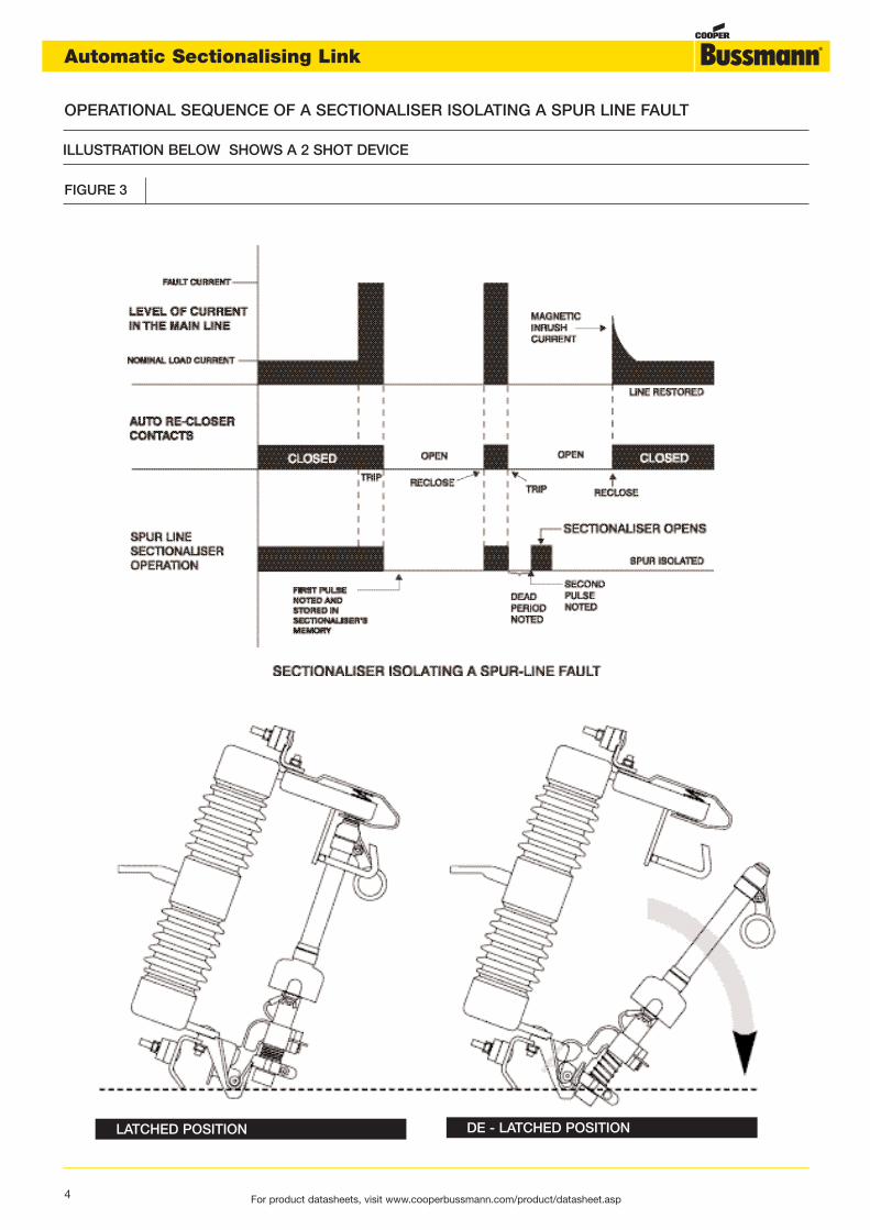
ILLUSTRATION BELOW SHOWS A 2 SHOT DEVICE
OPERATIONAL SEQUENCE OF A SECTIONALISER ISOLATING A SPUR LINE FAULT
LATCHED POSITION DE - LATCHED POSITION
FIGURE 3
4 For product datasheets, visit www.cooperbussmann.com/product/datasheet.asp
Automatic Sectionalising Link

5
Historically in many countries using a low impedience earthed3-wire overhead line system the individual protection of aspur line is provided by explusion type fuse-links which areintended to operate only during a persistent fault on thespur. In this group-fused system one fuse controls a groupof transformers in conjunction with either an upstream circuitbreaker having a multishot facility or an auto-recloser.
However in practice it has been found that there is a muchhigher proportion of fuse-link operations corresponding
Limitation of expulsion fuse-links and auto-reclose circuit breaker combination
Application
to ‘non-damage’ faults than damage faults. To reduce non-damage faults some utilities replaced all fuse-links beyondthe auto-recloser with solid links and the auto-recloser setfor instantaneous trips. The disadvantages of this so called‘solid system’ is the increased zone protected by the reclosingdevice leading to a greater number of consumers effected byeach fault on a spur line.
The availability of the ASL now achieves the discriminationfeature of providing individual spur protection without thedisadvantages of non-damage fault fuse-link operations.
The intended performance of expulsion fuse-links fitted atthe major spurs and an upstream auto-recloser (equippedwith one instantaneous and followed by at least one delayedtrip) is that for non-damaged faults on a fused spur, thecircuit breaker trips instantaneously and the fuse-link elementremains intact. The auto-recloser recloses after the deadtime with the fault no longer present thus restoring supplyto all customers.
For damage faults, the auto-recloser trips instantaneouslyand the fuse-link element remains intact. The auto-recloserrecloses after dead time but as the fault is still present thefuse-link operates before the delayed protection of the auto-recloser. When the auto-recloser closes for the third time allcustomers have supply except those beyond the fuse.
However in practice, as shown by the diagram, there existsa current where the fuse-link characteristic crosses theinstantaneous characteristic of the auto-recloser. This leadsto a proportion of fuse-links operating before or during thebreaker operation. If a fault is permanent nothing is lost, butif a fault is of the non-damage type a non-damage fuse-linkoperation will occur.
Such non-damage fuse-link operations are widely un-welcomeand are most widely associated with lightning strikes, whichcan produce these high current transients.
In addition, for low earth fault currents, there will be a zonewhere the expulsion fuse-link will not operate during thedelayed protection of the auto-recloser resulting in lockoutof the auto-recloser. This will lead to all customers downsteamfrom the auto-recloser losing supply rather than just thoseon the faulty spur with a subsequent increase in customerminutes lost.
Typically for a 30A type T expulsion fuse-link, the 10 secondmelting time is 120A leaving a large zone of fault currentsbelow this where lockout of the auto-recloser will occur.Recent measurement studies have shown that in the caseof one UK utility 50% of earth faults were less than 100Amps. Conventional group fusing would have resulted inrecloser lockout for these faults, as would operation of a‘solid system’.
In summary there is a limit to the coordination zone forexpulsion fuse-links and auto-recloser combinations. Lowcurrent permanent earth faults and high current transientfaults cannot be correctly coordinated.
For product datasheets, visit www.cooperbussmann.com/product/datasheet.asp
Automatic Sectionalising Link

CURRENT (A)
TIM
E IN
SE
CO
ND
S
AUTO-RECLOSER FUSE CO-ORDINATION
6 For product datasheets, visit www.cooperbussmann.com/product/datasheet.asp
Automatic Sectionalising Link

Advantages of ASL and auto-reclosing circuit breaker combination
As illustrated in the co-ordination diagram, the main advantageof the ASL is that discrimination with pole mounted auto-recloser or ground mounted multishot circuit breaker isassured down to the minimum operating current of the ASLwithout the necessity for delayed trips. Auto-reclosers cantherefore be set for instantaneous trip thus minimising systemdamage. Fault withstand is not an issue as the short time-current withstand rating of the ASL will be greater than theavailable fault current except for a few possible applicationsnext to a substation.
In the case of low earth fault currents, by selecting an ASLwith minimum pick up current at or below the minimum tripcurrent of the auto-recloser where possible,
these earth faults will result in operation of the ASL on thefaulty spur, thus preventing lockout of the recloser and wideloss of supply to customers.To achieve the optimum levelof co-ordination and to take account of tolerances, the lowestrating of ASL should be 80% of the earth fault or sensitiveearth fault settings, dependent on the scheme employed.
The diagram below illustrates an enhanced protection schemeutilising the full potential of the ASL’s. Any permanent faulton the spurs fitted with the ASL’s that causes recloseoperations of the PMAR will also cause operation of the ASLin the faulted spur.
PMAR
50 Amp3 count ASL
Spur Line
16A2 count ASL
Earth Fault
Pole mounted Auto re-closerLOWEST E/F or SEF 20A
Main overhead line
16A2 count ASL
16A2 count ASL
ENHANCED PROTECTION SCHEME USING AUTOMATIC SECTIONALISING LINKS
With a conservative estimate of £100 for the cost of a callout for a two men crew, application of an ASL on a spur location canbe easily justified when more than two nuisance outages would otherwise occur over the expected life of the ASL. Assuming a20 year life expectancy, an ASL is justified where there are more then 0.1 non damage fuse-link operations per spur location peryear. In practice, dependent on the loading on the spur, typically it has been found that an ASL is cost effective for spur lineslonger than 1 to 3 Km. For spur lines longer than 4 to 6 Km further economic sectionalising of the line will be achieved by putting2 ASL’s in series. In this case the downstream ASL will have one less count than the upstream ASL as shown in fig. 4.
ASL
ASL
ASL
ASL
FIGURE 4
7For product datasheets, visit www.cooperbussmann.com/product/datasheet.asp
Automatic Sectionalising Link

AUTO-RECLOSER ASL CO-ORDINATION
CURRENT (A)
TIM
E IN
SE
CO
ND
S
8 For product datasheets, visit www.cooperbussmann.com/product/datasheet.asp
Automatic Sectionalising Link

In the United States the most common type of overheadprimary distribution circuit is the four-wire multiearthed –neutral system. A typical distribution system will be similarto that in figure 5. A main line (feeder) with an auto-reclosernear its head originates from a substation with several spurs(laterals) tapped off this feeder. Often further branch linesare tapped off the spur (lateral) which in turn supply powerto end users. Individual transformers are individually fusedand also fuses at the head of branches and laterals providefurther sectionalising of the system.
Typically the individual transformer fuse-links are selectedsuch that they will operate on all selected overcurrents withoutcausing the auto-recloser to trip. Operation of this fuse-linkaffects a small number of customers thus minimising theeffects of any nuisance operations.
The fuse-link at the head of the lateral or branch co-ordinateswith the auto-recloser in the same way so described for thegroup fused system with some of the same limitations. Thereis a maximum current beyond
which the fuse-link will operate before the recloser has achance to clear a temporary fault.Under high transient faultconditions, such as caused by lightning, nuisance fuse-linkblowing can result. As these circuits are characterised bycomparitively high earth fault currents fuse-links are usedeffectively for earth fault protection
Most of the distribution circuits have at least two expulsionfuse-links in series. Due to the non-current limiting natureof expulsion fuse-links there is a maximum current at whichco-ordination can be achieved. Above this current it is likelythat both the upstream and downstream expulsion fuse-links will operate at the same time.
In both examples it is the common feature of the fuse at thehead of the lateral (spur) that gives rise to the limitations inoperational performance.
By replacing a fuse with an ASL at the head of a lateral orbranch as in figure 6 the co-ordination range is extended tothe maximum short time withstand rating of the ASL.
North American Practice
9For product datasheets, visit www.cooperbussmann.com/product/datasheet.asp
Automatic Sectionalising Link

TYPICAL NORTH AMERICAN DISTRIBUTION SYSTEM
PMAR
CutoutSpur Line
or lateral
Pole mounted Auto re-closer
Main overhead line or feeder
Transformer
Cutout
PMAR
3 count ASL
Spur Line
or lateral
Pole mounted Auto re-closer
Main overhead line or feeder
Transformer
Cutout
2 count ASL
2 count ASL
2 count ASL
ASL
ASL
ASL
ASL
FIGURE 5
FIGURE 6
TYPICAL NORTH AMERICAN DISTRIBUTION SYSTEM USING AUTOMATIC SECTIONASING LINKS
10 For product datasheets, visit www.cooperbussmann.com/product/datasheet.asp
Automatic Sectionalising Link
Selection
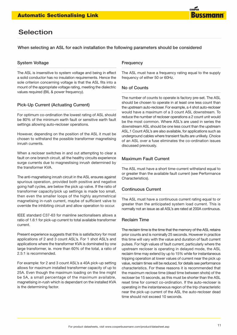
System Voltage
The ASL is insensitive to system voltage and being in effecta solid conductor has no insulation requirements. Hence thesole criterion concerning voltage is that the ASL fits into amount of the appropriate voltage rating, meeting the dialectricvalues required (BIL & power frequency).
Pick-Up Current (Actuating Current)
For optimum co-ordination the lowest rating of ASL shouldbe 80% of the minimum earth fault or sensitive earth faultsettings allowing auto-recloser operations.
However, depending on the position of the ASL it must bechosen to withstand the possible transformer magnetisinginrush currents.
When a recloser switches in and out attempting to clear afault on one branch circuit, all the healthy circuits experiencesurge currents due to magnestising inrush determined bythe transformer KVA.
The anti-magnetising inrush circuit in the ASL ensures againstspurious operation, provided both positive and negativegoing half cycles, are below the pick up valve. If the ratio oftransformer capacity/pick up settings is made too small,then even the smaller loops of the highly asymmetricalmagnetising in-rush current, maybe of sufficient valve tooverride the inhibiting circuit and allow operation to occur.
IEEE standard C37-63 for mainline sectionalisers allows aratio of 1.6:1 for pick-up current to total available transformercurrent.
Present experience suggests that this is satisfactory for mostapplications of 2 and 3 count ASL’s. For 1 shot ASL’s andapplications where the transformer KVA is dominated by onelarge transformer, ie. more than 60% of the total, a ratio of2.5:1 is recommended.
For example: for 2 and 3 count ASL’s a 40A pick-up settingallows for maximum installed transformer capacity of up to25A. Even though the maximum loading on the line mightbe 5A, a small percentage of the maximum available,magnetising in-rush which is dependant on the installed KVAis the determining factor.
Frequency
The ASL must have a frequency rating equal to the supplyfrequency of either 50 or 60Hz.
No of Counts
The number of counts to operate is factory pre-set. The ASLshould be chosen to operate in at least one less count thanthe upstream auto-recloser. For example, a 4 shot auto-recloserwould have a maximum of a 3 count ASL downstream. Toreduce the number of recloser operations a 2 count unit wouldbe the most common. Where ASL’s are used in series thedownstream ASL should be one less count than the upstreamASL.1 Count ASL’s are also available, for applications such asunderground cables where transient faults are unlikely. Choiceof an ASL over a fuse eliminates the co-ordination issuesdiscussed previously.
Maximum Fault Current
The ASL must have a short time-current withstand equal toor greater than the available fault current (see PerformanceCharacteristics).
Continuous Current
The ASL must have a continuous current rating equal to orgreater than the anticipated system load current. This isnormally not an issue as all ASL’s are rated at 200A continuous.
Reclaim Time
The reclaim time is the time that the memory of the ASL retainsprior counts and is nominally 25 seconds. However in practicethis time will vary with the value and duration of fault currentpulses. For high values of fault current, particularly where theupstream recloser is operating in delayed mode, the ASLreclaim time may extend by up to 15% while for instantaneoustripping operation at lower values of current near the pick upvalue, reclaim times will be reduced, for details see performancecharacteristics. For these reasons it is recommended thatthe maximum reclose time (dead time between shots) of therecloser be 15 seconds, as this must be shorter than the ASLreset time for correct co-ordination. If the auto-recloser isoperating in the instantaneous region of the trip characteristicnear the pick-up current of the ASL the auto-recloser deadtime should not exceed 10 seconds.
When selecting an ASL for each installation the following parameters should be considered
11For product datasheets, visit www.cooperbussmann.com/product/datasheet.asp
Automatic Sectionalising Link
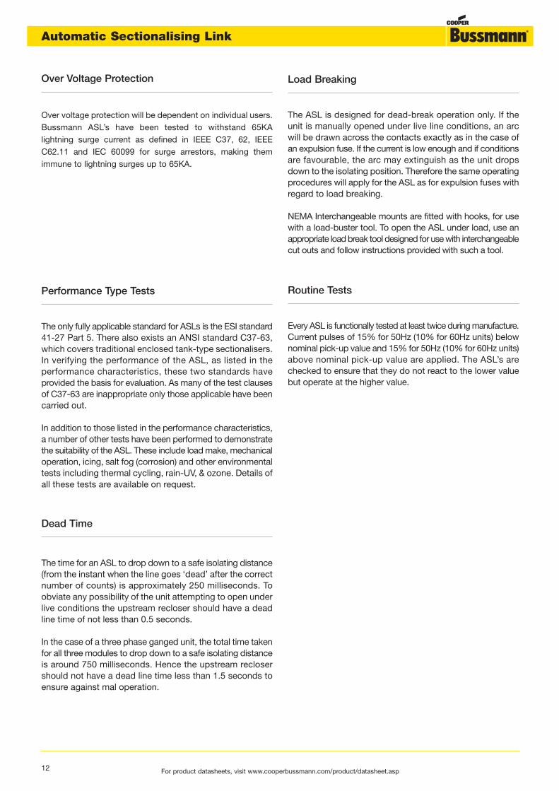
Over Voltage Protection
Over voltage protection will be dependent on individual users.Bussmann ASL’s have been tested to withstand 65KAlightning surge current as defined in IEEE C37, 62, IEEEC62.11 and IEC 60099 for surge arrestors, making themimmune to lightning surges up to 65KA.
Load Breaking
The ASL is designed for dead-break operation only. If theunit is manually opened under live line conditions, an arcwill be drawn across the contacts exactly as in the case ofan expulsion fuse. If the current is low enough and if conditionsare favourable, the arc may extinguish as the unit dropsdown to the isolating position. Therefore the same operatingprocedures will apply for the ASL as for expulsion fuses withregard to load breaking.
NEMA Interchangeable mounts are fitted with hooks, for usewith a load-buster tool. To open the ASL under load, use anappropriate load break tool designed for use with interchangeablecut outs and follow instructions provided with such a tool.
Performance Type Tests
The only fully applicable standard for ASLs is the ESI standard41-27 Part 5. There also exists an ANSI standard C37-63,which covers traditional enclosed tank-type sectionalisers.In verifying the performance of the ASL, as listed in theperformance characteristics, these two standards haveprovided the basis for evaluation. As many of the test clausesof C37-63 are inappropriate only those applicable have beencarried out.
In addition to those listed in the performance characteristics,a number of other tests have been performed to demonstratethe suitability of the ASL. These include load make, mechanicaloperation, icing, salt fog (corrosion) and other environmentaltests including thermal cycling, rain-UV, & ozone. Details ofall these tests are available on request.
Routine Tests
Every ASL is functionally tested at least twice during manufacture.Current pulses of 15% for 50Hz (10% for 60Hz units) belownominal pick-up value and 15% for 50Hz (10% for 60Hz units)above nominal pick-up value are applied. The ASL’s arechecked to ensure that they do not react to the lower valuebut operate at the higher value.
12 For product datasheets, visit www.cooperbussmann.com/product/datasheet.asp
Dead Time
The time for an ASL to drop down to a safe isolating distance(from the instant when the line goes ‘dead’ after the correctnumber of counts) is approximately 250 milliseconds. Toobviate any possibility of the unit attempting to open underlive conditions the upstream recloser should have a deadline time of not less than 0.5 seconds.
In the case of a three phase ganged unit, the total time takenfor all three modules to drop down to a safe isolating distanceis around 750 milliseconds. Hence the upstream reclosershould not have a dead line time less than 1.5 seconds toensure against mal operation.
Automatic Sectionalising Link

* A 2 or 3 pole mechanically ganged mount is available which accepts the ASL type BR1T, for applications where it isrequired to isolate all phases, even for a single phase fault. Operation of the ASL in one phase automatically operates aninterphase trip mechanism, which causes the remaining phases to open.
Mounting Arrangements
A variety of ASL’s are available to fit the most common typesof expulsion fuse mount as shown in the table below.
Bussmann ASL Reference Suitable for Mount type Replacement Actuator
BR1 S & E Equipment, pre. 1967 E2906
BR2 Brush Power (1976-1987) E2906
BR3 Hawker Switchgear E2906
BR5 J & P (GEC) 2924
BR1M Morris Line Equipment E2906
BR1T* Morris Line Triple pole Unit E2906
C Interchangeable USA, NEMA E2906
CR5 Interchangeable USA NEMA E2906For UK with J & P Pole Head
Rated Maximum Voltage: 15kV (110kV BIL), 27kV (150kV BIL), 38kV (170kV BIL)
Rated Frequency: 50Hz, 60 Hz
Pick Up Current: 60Hz operation (±10%) 16, 24, 40, 56, 80, 112, 160, 200, 320 Amps
50Hz operation (±15%) 15, 20, 25, 40, 50, 63, 80, 100, 200, 320 Amps
Number of counts: 1, 2 or 3
Hold off current: 250 milliamps
Current Withstand: Continuous 200A
Momentary 1st peak 16,000 Amps
1 sec 8000 Amps Symmetrical
10 sec 2600 Amps Symmetrical
Reclaim times: 25 seconds (±15%)
Response time:Minimum duration of current pulse 30 msec @ 1.5 X pick up setting (reclaim time 10 seconds)
for overcurrent memory response: 60 msec @ 1.3 X pick up setting (reclaim time 15 seconds)
Auto-recloser dead time range: 0.5 sec to 15 sec
Minimum time of dead line after fault pulse for count: 80 - 120 msec
Ambient temperature limits: -30ºC to 80ºC
Surge Current withstand: 65KA per ANSI C37, 63 IEEE 62.11 & IEC EN60099-1
Performance Characteristics
13For product datasheets, visit www.cooperbussmann.com/product/datasheet.asp
Automatic Sectionalising Link

BR3
14 For product datasheets, visit www.cooperbussmann.com/product/datasheet.asp
Automatic Sectionalising Link

BR5
15For product datasheets, visit www.cooperbussmann.com/product/datasheet.asp
Automatic Sectionalising Link
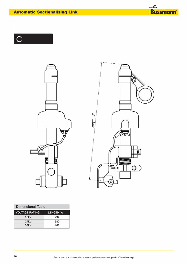
C
VOLTAGE RATING LENGTH ‘A’
15kV 292
27kV 380 38kV 468
Dimensional Table
16 For product datasheets, visit www.cooperbussmann.com/product/datasheet.asp
Automatic Sectionalising Link

In general the installation procedure for the ASL is similarto that for the equivalent fuse carrier, in that the samepolehead is used but an actuator is replaced after operationinstead of an expulsion fuse-link. Detailed installationinstructions are available with every ASL and also on request.
A common actuator E2906 fits all types of ASL except typeBR5 for the J & P mount. For this unit actuator 2924 shouldbe used, which is the same as E2906 except for an extraboot. The purpose of the boot is to provide additionalenvironmental protection as the BR5 unit is the only ASL withthe actuator fitted to the top contact.
Installation
The general procedure for replacing the actuator is to slackenoff the wing nut and withdraw the spade terminal. Unscrewthe actuator and discard spent actuator assembly. Screwin new actuator until finger tight in it’s housing. Lightly smearcontact grease to both sides of actuator spade terminal.Wipe clean flat face of actuator terminal on main body ofASL and smear light covering of grease. Locate spadeterminal under washer and wing nut & then tighten wing nut.
UPPERCONTACT
LIFTINGTANG
LIFTINGTANG
TANG A
ACTUATOR
ACTUATOR
CONTACTMECHANISM
TERMINALCOVER
SPADETERMINAL
17For product datasheets, visit www.cooperbussmann.com/product/datasheet.asp
Automatic Sectionalising Link

For product datasheets, visit www.cooperbussmann.com/product/datasheet.asp
TYPE ASL XX C DESIGNED FOR USE WITH NEMA STYLE FUSE MOUNTS
18 For product datasheets, visit www.cooperbussmann.com/product/datasheet.asp
Automatic Sectionalising Link

Colour Coding Identification
PICK UP CURRENTColoured band below current transformer
NUMBER OF COUNTSColoured band above current transformer
60 HZ operation (suffix US) 50 Hz operation 1 count Brown
16A Yellow 20A Yellow 2 count No Band
24A Red 25A Red 3 count Green
40A Blue 40A Blue
56A Green 50A Green
80A Black 63A Black
112A White 80A Brown
160A Brown 100A White
224A Orange 200A Orange
320A No band
Colour Coding Information
19For product datasheets, visit www.cooperbussmann.com/product/datasheet.asp
Automatic Sectionalising Link

PICK UP CURRENT (50Hz only)
20A YELLOW
25A RED
40A BLUE
50A GREEN
63A BLACK
80A BROWN
100A WHITE
200A ORANGE
NUMBER OF SHOTS
1 COUNT BROWN
2 COUNT NO BAND
3 COUNT GREEN
COLOUR BAND DIAGRAM SHOWS ASL TYPE BR5
AUTOMATIC SECTIONALISING LINK - COLOUR BANDS
20 For product datasheets, visit www.cooperbussmann.com/product/datasheet.asp
Automatic Sectionalising Link
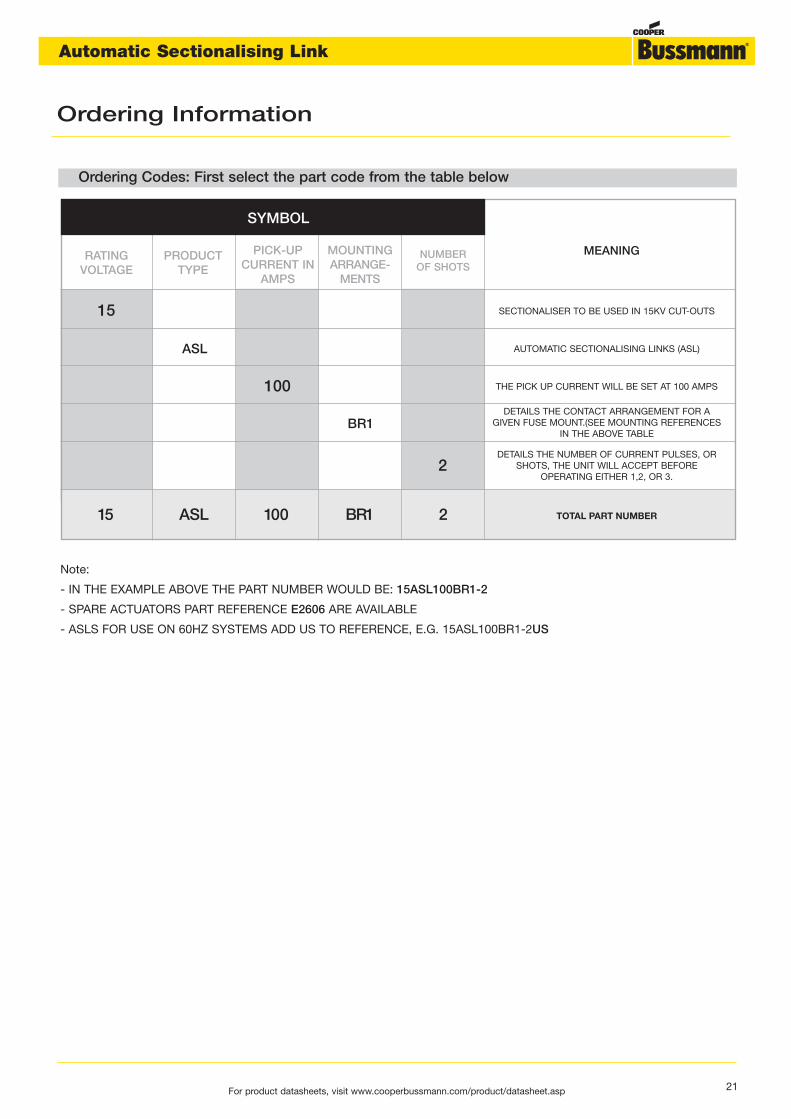
SYMBOL
RATING VOLTAGE
15 SECTIONALISER TO BE USED IN 15KV CUT-OUTS
AUTOMATIC SECTIONALISING LINKS (ASL)
THE PICK UP CURRENT WILL BE SET AT 100 AMPS
DETAILS THE CONTACT ARRANGEMENT FOR AGIVEN FUSE MOUNT.(SEE MOUNTING REFERENCES
IN THE ABOVE TABLE
DETAILS THE NUMBER OF CURRENT PULSES, ORSHOTS, THE UNIT WILL ACCEPT BEFORE
OPERATING EITHER 1,2, OR 3.
ASL
100
BR1
2
PRODUCTTYPE
PICK-UPCURRENT IN
AMPS
MOUNTINGARRANGE-
MENTS
NUMBER OF SHOTS
MEANING
15 ASL 100 BR1 2 TOTAL PART NUMBER
Ordering Codes: First select the part code from the table below
Note:
- IN THE EXAMPLE ABOVE THE PART NUMBER WOULD BE: 15ASL100BR1-2
- SPARE ACTUATORS PART REFERENCE E2606 ARE AVAILABLE
- ASLS FOR USE ON 60HZ SYSTEMS ADD US TO REFERENCE, E.G. 15ASL100BR1-2US
Ordering Information
21For product datasheets, visit www.cooperbussmann.com/product/datasheet.asp
Automatic Sectionalising Link

22
Notes
For product datasheets, visit www.cooperbussmann.com/product/datasheet.asp
Automatic Sectionalising Link

Notes
23For product datasheets, visit www.cooperbussmann.com/product/datasheet.asp
Automatic Sectionalising Link