cooper b-line - v-line cabinet systems - complete catalog
TRANSCRIPT
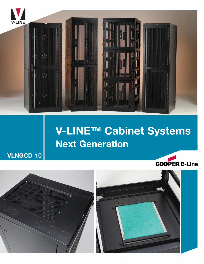
V-LINE™ Cabinet SystemsNext Generation
VLNGCD-10

2
Product Introduction
Today’s competitive electronic enclosure market requires cost effective productsthat deliver superior performance and function. Cooper B-Line developed theV-LINE™ cabinet platform to support the growing need for a competitively pricedsolution.
Many innovative features are designed into the V-LINE cabinet platform, offeringvaluable benefits for users. The heart of the system, the cabinet frame, has standard
features, such as, fully adjustable mounting angles with RMU markings, removable and replaceable cableentry plates, and leveling feet. The frame can be fitted with a range of options including solid or ventedside panels, a variety of door styles, and top or bottom panels. The V-LINE cabinet features excellentaesthetic characteristics and is built to the high quality standard our customers have come to expectover the years from Cooper B-Line.
All of these features, good looks and high quality are offered at a competitive price point, makingthe V-LINE cabinet an excellent choice for anyone needing to house data communications equipmentwhile watching the bottom line.
Removable cable entryknockout plates
Fully adjustable 19” rails.291/2” wide cabinet offeroffset and 23” mounting
Square hole or #12-24tapped hole mounting railoptions
Range of single & doubledoor options with a varietyof locking choices
Doors can be configured lefthand (LH) or right hand (RH)hinged
New ganging knockoutsallow cabinets to beganged with or withoutside panels
Leveling feet supplied asstandard with optionalcastor availability
Extensive range ofmechanical andelectronic lockingoptions
Lockable side panels
Fully configurable toppanel assembly
Plain & vented sidepanel options
Open base with infillpanel & filter options
Standard cabinet finish is a Black hard wearing epoxy polyester powder coat paint, color reference RAL 9005.Cabinets are also available finished in Light Gray, reference NCS 1502-Y, but may be subject to increased lead times.
Fully welded steelframe structure
The V-LINE™ Cabinet Advantage
Table Of Contents
3
Table of ContentsProduct Introduction . . . . . . . . . . . . . . . . . . . . . . . . . . . . . . . . . . . . . . . . . . . . . . . . . . . . . . . . . . . . . . . . . . . . . . . . . . . . . . . . . . . . . . . . . . . . . . . . . . . . . . . . . . . . . 2
Table of Contents . . . . . . . . . . . . . . . . . . . . . . . . . . . . . . . . . . . . . . . . . . . . . . . . . . . . . . . . . . . . . . . . . . . . . . . . . . . . . . . . . . . . . . . . . . . . . . . . . . . . . . . . . . . . . . . . . 3
Cabinet System . . . . . . . . . . . . . . . . . . . . . . . . . . . . . . . . . . . . . . . . . . . . . . . . . . . . . . . . . . . . . . . . . . . . . . . . . . . . . . . . . . . . . . . . . . . . . . . . . . . . . . . . . . . . . . . . . . . 4
Easy Step Configurator . . . . . . . . . . . . . . . . . . . . . . . . . . . . . . . . . . . . . . . . . . . . . . . . . . . . . . . . . . . . . . . . . . . . . . . . . . . . . . . . . . . . . . . . . . . . . . . . . . . . . . . . . 5
V-LINE™ Cabinet OptionsNetwork Cabinet . . . . . . . . . . . . . . . . . . . . . . . . . . . . . . . . . . . . . . . . . . . . . . . . . . . . . . . . . . . . . . . . . . . . . . . . . . . . . . . . . . . . . . . . . . . . . . . . . . . . . . . . . . . . . . . . . . 6
Cabling Cabinet . . . . . . . . . . . . . . . . . . . . . . . . . . . . . . . . . . . . . . . . . . . . . . . . . . . . . . . . . . . . . . . . . . . . . . . . . . . . . . . . . . . . . . . . . . . . . . . . . . . . . . . . . . . . . . . . . . . 7
Server Cabinet . . . . . . . . . . . . . . . . . . . . . . . . . . . . . . . . . . . . . . . . . . . . . . . . . . . . . . . . . . . . . . . . . . . . . . . . . . . . . . . . . . . . . . . . . . . . . . . . . . . . . . . . . . . . . . . . . . . . . 8
Switch Cabinet . . . . . . . . . . . . . . . . . . . . . . . . . . . . . . . . . . . . . . . . . . . . . . . . . . . . . . . . . . . . . . . . . . . . . . . . . . . . . . . . . . . . . . . . . . . . . . . . . . . . . . . . . . . . . . . . . . . . 9
Co-Locate Cabinet . . . . . . . . . . . . . . . . . . . . . . . . . . . . . . . . . . . . . . . . . . . . . . . . . . . . . . . . . . . . . . . . . . . . . . . . . . . . . . . . . . . . . . . . . . . . . . . . . . . . . . . . . . . . . . 10
Co-Locate Easy Step Configurator . . . . . . . . . . . . . . . . . . . . . . . . . . . . . . . . . . . . . . . . . . . . . . . . . . . . . . . . . . . . . . . . . . . . . . . . . . . . . . . . . . . . . . . . . 11
Front & Rear Door Options (Door styles & locking options) . . . . . . . . . . . . . . . . . . . . . . . . . . . . . . . . . . . . . . . . . . . . . . . . . . . . . . . . . 12-13
Side Panel Options . . . . . . . . . . . . . . . . . . . . . . . . . . . . . . . . . . . . . . . . . . . . . . . . . . . . . . . . . . . . . . . . . . . . . . . . . . . . . . . . . . . . . . . . . . . . . . . . . . . . . . . . . . . . . 14
Bottom Panel Options . . . . . . . . . . . . . . . . . . . . . . . . . . . . . . . . . . . . . . . . . . . . . . . . . . . . . . . . . . . . . . . . . . . . . . . . . . . . . . . . . . . . . . . . . . . . . . . . . . . . . . . . . 15
Top Panel Options . . . . . . . . . . . . . . . . . . . . . . . . . . . . . . . . . . . . . . . . . . . . . . . . . . . . . . . . . . . . . . . . . . . . . . . . . . . . . . . . . . . . . . . . . . . . . . . . . . . . . . . . . . . . . . 16
V-LINE™ AccessoriesCaster Kits, Seismic Bolt-Down Kit, Cable Entry Knockout Plates . . . . . . . . . . . . . . . . . . . . . . . . . . . . . . . . . . . . . . . . . . . . . 17
Brush Strip Cable Plates, Mounting Rail Offset Kits . . . . . . . . . . . . . . . . . . . . . . . . . . . . . . . . . . . . . . . . . . . . . . . . . . . . . . . . . . . . . . . . 18
Air Dam Kits, Vertical Cable Manager Kits . . . . . . . . . . . . . . . . . . . . . . . . . . . . . . . . . . . . . . . . . . . . . . . . . . . . . . . . . . . . . . . . . . . . . . . . . . . . . 19
Ganging Kits, Earth kits, Screws & Cage Nuts . . . . . . . . . . . . . . . . . . . . . . . . . . . . . . . . . . . . . . . . . . . . . . . . . . . . . . . . . . . . . . . . . . . . . . . . 20
Enhanced Vertical Cable Manager Kits, Horizontal Cable Trough Kits . . . . . . . . . . . . . . . . . . . . . . . . . . . . . . . . . . . . . . . . 21
Horizontal Cable Managers, Twist & Lock Arms and Rings . . . . . . . . . . . . . . . . . . . . . . . . . . . . . . . . . . . . . . . . . . . . . . . . . . . . . . 22
PlenaFill Plastic Blanking Panels, Quick Fit Blanking Panels . . . . . . . . . . . . . . . . . . . . . . . . . . . . . . . . . . . . . . . . . . . . . . . . . . . 23
Adjustable Side Depth Blanking Panels, Cable Guide Kit, Narrow Cable Hoop Kit . . . . . . . . . . . . . . . . . . . . . . . 24
Cantilever Shelves, Quick Fit Shelves, Fixed Shelves . . . . . . . . . . . . . . . . . . . . . . . . . . . . . . . . . . . . . . . . . . . . . . . . . . . . . . . . . . . . . . . 25
Sliding Shelves, Universal Sliding Shelves . . . . . . . . . . . . . . . . . . . . . . . . . . . . . . . . . . . . . . . . . . . . . . . . . . . . . . . . . . . . . . . . . . . . . . . . . . . 26
Other Comm/Data Products . . . . . . . . . . . . . . . . . . . . . . . . . . . . . . . . . . . . . . . . . . . . . . . . . . . . . . . . . . . . . . . . . . . . . . . . . . . . . . . . . . . . . . . . . . . . . . . . . . . 27

4
Cabinet System
Side ViewWith Split Panel
Side ViewWith Single Panel
Front ViewWith Single Door
Top ViewBottom View
OverallDepth
FrameDepth
OverallDepth
FrameDepth
Width
Width
1”Door
1”Door
1”Door
1”Door
“U” Height+
0.13”
2.63”Top & Bottom
2.80”
22.72”
0.93”
Jacking Foottypical four (4)
positions
0.93”
3.15”
3.15”
OverallHeight
Basic DimensionsAll dimensions are provided in inches.
Details subject to change without written notice.
For overall unit sizes see cabinet configuration tables.
Castor centerstypical four (4)
positions
Easy Step Configurator
5
V
Step
1St
ep 2
Step
4St
ep 3
42
24
42
A
C
V
X
S
S
S
VStep
5St
ep 6
Step
7
B
+
V-LINE CabinetRange
CabinetEffective Height
CabinetOverall Width
CabinetOverall Depth
Mounting RailType
Mounting RailPosition
Front Door
Rear Door
Locking Options
Left Hand (LH) Side Panel Configuration
Right Hand (RH) Side Panel Configuration
Top PanelConfiguration
Finish
Accessories
Options
24U 38U 42U 45U 47U
24 = 24” 29 = 291/2”
24 = 24” 30 = 30” 36 = 36” 42 = 42” 48 = 48”
A = 19” Square Holes C = 23” Square Holes *B = 19” #12-24 Tapped Holes D = 23” #12-24 Tapped Holes *
* Only on 291/2” wide cabinets
L = Offset Left*R = Offset Right* * Only on 291/2” wide cabinetsC = Centered
V = High Flow Vented LH A = Acrylic LHW = High Flow Vented RH B = Acrylic RHX = High Flow Vented Split* C = Vented Acrylic LHS = Solid LH D = Vented Acrylic RHT = Solid RH F = Split Fan Door*U = Solid Split*N = None
S = Swing Handle (single point) D = Combo Handle (3-point)C = Combo Handle (single point) P = i-PAL Handle (2-point)T = Swing Handle (3-point) N = None
S = Solid Full Height*T = Solid Split**V = Vented Full Height*W = Vented Split**N = None
S = Solid Top 2 = 210 CFM Fan Top 1 = 1100 CFM Fan Top*V = Vented Top 4 = 420 CFM Fan Top * Not available on 24” wideN = None 5 = 550 CFM Fan Top deep units
A = Gray B = Black
See Pages 17 - 26
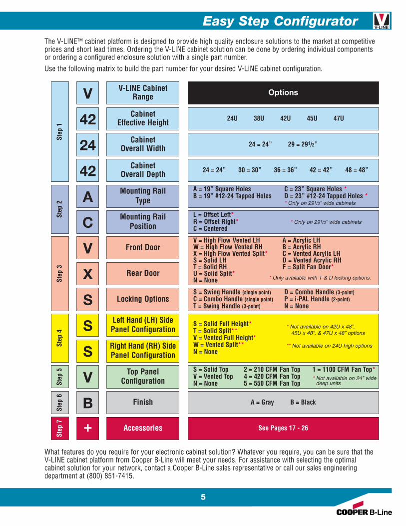
The V-LINE™ cabinet platform is designed to provide high quality enclosure solutions to the market at competitiveprices and short lead times. Ordering the V-LINE cabinet solution can be done by ordering individual componentsor ordering a configured enclosure solution with a single part number.
Use the following matrix to build the part number for your desired V-LINE cabinet configuration.
What features do you require for your electronic cabinet solution? Whatever you require, you can be sure that theV-LINE cabinet platform from Cooper B-Line will meet your needs. For assistance with selecting the optimalcabinet solution for your network, contact a Cooper B-Line sales representative or call our sales engineeringdepartment at (800) 851-7415.
* Not available on 42U x 48”,45U x 48”, & 47U x 48” options
** Not available on 24U high options
* Only available with T & D locking options.
6
Network Cabinet
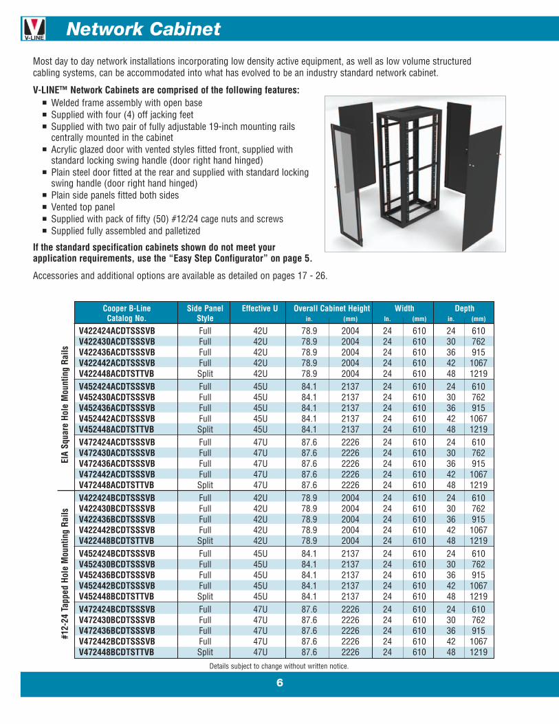
Most day to day network installations incorporating low density active equipment, as well as low volume structuredcabling systems, can be accommodated into what has evolved to be an industry standard network cabinet.
V-LINE™ Network Cabinets are comprised of the following features:n Welded frame assembly with open basen Supplied with four (4) off jacking feetn Supplied with two pair of fully adjustable 19-inch mounting rails
centrally mounted in the cabinetn Acrylic glazed door with vented styles fitted front, supplied with
standard locking swing handle (door right hand hinged)n Plain steel door fitted at the rear and supplied with standard locking
swing handle (door right hand hinged)n Plain side panels fitted both sidesn Vented top paneln Supplied with pack of fifty (50) #12/24 cage nuts and screwsn Supplied fully assembled and palletized
If the standard specification cabinets shown do not meet yourapplication requirements, use the “Easy Step Configurator” on page 5.
Accessories and additional options are available as detailed on pages 17 - 26.
Cooper B-Line Side Panel Effective U Overall Cabinet Height Width DepthCatalog No. Style in. (mm) In. (mm) in. (mm)
V422424ACDTSSSVB Full 42U 78.9 2004 24 610 24 610V422430ACDTSSSVB Full 42U 78.9 2004 24 610 30 762V422436ACDTSSSVB Full 42U 78.9 2004 24 610 36 915V422442ACDTSSSVB Full 42U 78.9 2004 24 610 42 1067V422448ACDTSTTVB Split 42U 78.9 2004 24 610 48 1219V452424ACDTSSSVB Full 45U 84.1 2137 24 610 24 610V452430ACDTSSSVB Full 45U 84.1 2137 24 610 30 762V452436ACDTSSSVB Full 45U 84.1 2137 24 610 36 915V452442ACDTSSSVB Full 45U 84.1 2137 24 610 42 1067V452448ACDTSTTVB Split 45U 84.1 2137 24 610 48 1219V472424ACDTSSSVB Full 47U 87.6 2226 24 610 24 610V472430ACDTSSSVB Full 47U 87.6 2226 24 610 30 762V472436ACDTSSSVB Full 47U 87.6 2226 24 610 36 915V472442ACDTSSSVB Full 47U 87.6 2226 24 610 42 1067V472448ACDTSTTVB Split 47U 87.6 2226 24 610 48 1219V422424BCDTSSSVB Full 42U 78.9 2004 24 610 24 610V422430BCDTSSSVB Full 42U 78.9 2004 24 610 30 762V422436BCDTSSSVB Full 42U 78.9 2004 24 610 36 915V422442BCDTSSSVB Full 42U 78.9 2004 24 610 42 1067V422448BCDTSTTVB Split 42U 78.9 2004 24 610 48 1219V452424BCDTSSSVB Full 45U 84.1 2137 24 610 24 610V452430BCDTSSSVB Full 45U 84.1 2137 24 610 30 762V452436BCDTSSSVB Full 45U 84.1 2137 24 610 36 915V452442BCDTSSSVB Full 45U 84.1 2137 24 610 42 1067V452448BCDTSTTVB Split 45U 84.1 2137 24 610 48 1219V472424BCDTSSSVB Full 47U 87.6 2226 24 610 24 610V472430BCDTSSSVB Full 47U 87.6 2226 24 610 30 762V472436BCDTSSSVB Full 47U 87.6 2226 24 610 36 915V472442BCDTSSSVB Full 47U 87.6 2226 24 610 42 1067V472448BCDTSTTVB Split 47U 87.6 2226 24 610 48 1219
Details subject to change without written notice.
EIA
Squa
re H
ole
Mou
ntin
g Ra
ils#1
2-24
Tap
ped
Hole
Mou
ntin
g Ra
ils

Cabling Cabinet
7
For applications housing structured cabling systems, it is often necessary to employ wider cabinets to adequatelyaccommodate the back bone cabling, as well as provide space to manage the patch cords.
V-LINE™ Cabling Cabinets are comprised of the following features:n 291/2” wide welded frame assembly with open basen Supplied with four (4) off jacking feetn Supplied with two pair of fully adjustable 19-inch mounting rails
centrally mounted in the cabinetn Acrylic glazed door with vented styles fitted front and configured
with standard locking swing handle (door right hand hinged)n Plain steel door fitted at the rear and configured with standard
locking swing handle (door right hand hinged)n Plain side panels fitted both sidesn Vented top paneln Supplied with pack of Fifty (50) #12/24 cage nuts and screwsn Supplied fully assembled and palletized
If the standard specification cabinets shown do not meet yourapplication requirements, use the “Easy Step Configurator” on page 5.
Accessories and additional options are available as detailed on pages 17 - 26.
Details subject to change without written notice.
Cooper B-Line Side Panel Effective U Overall Cabinet Height Width DepthCatalog No. Style in. (mm) In. (mm) in. (mm)
V422924ACDTSSSVB Full 42U 78.9 2004 29.5 750 24 610V422930ACDTSSSVB Full 42U 78.9 2004 29.5 750 30 762V422936ACDTSSSVB Full 42U 78.9 2004 29.5 750 36 915V422942ACDTSSSVB Full 42U 78.9 2004 29.5 750 42 1067V422948ACDTSTTVB Split 42U 78.9 2004 29.5 750 48 1219V452924ACDTSSSVB Full 45U 84.1 2137 29.5 750 24 610V452930ACDTSSSVB Full 45U 84.1 2137 29.5 750 30 762V452936ACDTSSSVB Full 45U 84.1 2137 29.5 750 36 915V452942ACDTSSSVB Full 45U 84.1 2137 29.5 750 42 1067V452948ACDTSTTVB Split 45U 84.1 2137 29.5 750 48 1219V472924ACDTSSSVB Full 47U 87.6 2226 29.5 750 24 610V472930ACDTSSSVB Full 47U 87.6 2226 29.5 750 30 762V472936ACDTSSSVB Full 47U 87.6 2226 29.5 750 36 915V472942ACDTSSSVB Full 47U 87.6 2226 29.5 750 42 1067V472948ACDTSTTVB Split 47U 87.6 2226 29.5 750 48 1219V422924BCDTSSSVB Full 42U 78.9 2004 29.5 750 24 610V422930BCDTSSSVB Full 42U 78.9 2004 29.5 750 30 762V422936BCDTSSSVB Full 42U 78.9 2004 29.5 750 36 915V422942BCDTSSSVB Full 42U 78.9 2004 29.5 750 42 1067V422948BCDTSTTVB Split 42U 78.9 2004 29.5 750 48 1219V452924BCDTSSSVB Full 45U 84.1 2137 29.5 750 24 610V452930BCDTSSSVB Full 45U 84.1 2137 29.5 750 30 762V452936BCDTSSSVB Full 45U 84.1 2137 29.5 750 36 915V452942BCDTSSSVB Full 45U 84.1 2137 29.5 750 42 1067V452948BCDTSTTVB Split 45U 84.1 2137 29.5 750 48 1219V472924BCDTSSSVB Full 47U 87.6 2226 29.5 750 24 610V472930BCDTSSSVB Full 47U 87.6 2226 29.5 750 30 762V472936BCDTSSSVB Full 47U 87.6 2226 29.5 750 36 915V472942BCDTSSSVB Full 47U 87.6 2226 29.5 750 42 1067V472948BCDTSTTVB Split 47U 87.6 2226 29.5 750 48 1219
EIA
Squa
re H
ole
Mou
ntin
g Ra
ils#1
2-24
Tap
ped
Hole
Mou
ntin
g Ra
ils
8
Server Cabinet
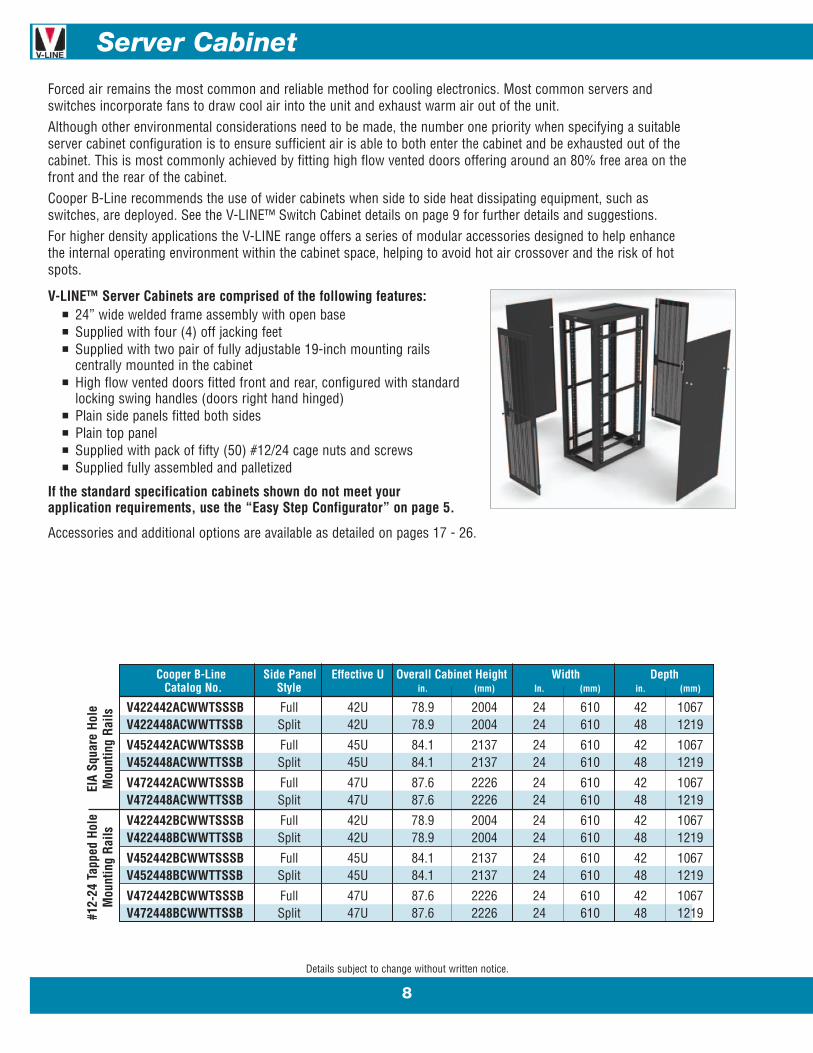
Forced air remains the most common and reliable method for cooling electronics. Most common servers andswitches incorporate fans to draw cool air into the unit and exhaust warm air out of the unit.Although other environmental considerations need to be made, the number one priority when specifying a suitableserver cabinet configuration is to ensure sufficient air is able to both enter the cabinet and be exhausted out of thecabinet. This is most commonly achieved by fitting high flow vented doors offering around an 80% free area on thefront and the rear of the cabinet.Cooper B-Line recommends the use of wider cabinets when side to side heat dissipating equipment, such asswitches, are deployed. See the V-LINE™ Switch Cabinet details on page 9 for further details and suggestions.For higher density applications the V-LINE range offers a series of modular accessories designed to help enhancethe internal operating environment within the cabinet space, helping to avoid hot air crossover and the risk of hotspots.
V-LINE™ Server Cabinets are comprised of the following features:n 24” wide welded frame assembly with open basen Supplied with four (4) off jacking feetn Supplied with two pair of fully adjustable 19-inch mounting rails
centrally mounted in the cabinetn High flow vented doors fitted front and rear, configured with standard
locking swing handles (doors right hand hinged)n Plain side panels fitted both sidesn Plain top paneln Supplied with pack of fifty (50) #12/24 cage nuts and screwsn Supplied fully assembled and palletized
If the standard specification cabinets shown do not meet yourapplication requirements, use the “Easy Step Configurator” on page 5.
Accessories and additional options are available as detailed on pages 17 - 26.
Details subject to change without written notice.
Cooper B-Line Side Panel Effective U Overall Cabinet Height Width DepthCatalog No. Style in. (mm) In. (mm) in. (mm)
V422442ACWWTSSSB Full 42U 78.9 2004 24 610 42 1067V422448ACWWTTSSB Split 42U 78.9 2004 24 610 48 1219
V452442ACWWTSSSB Full 45U 84.1 2137 24 610 42 1067V452448ACWWTTSSB Split 45U 84.1 2137 24 610 48 1219
V472442ACWWTSSSB Full 47U 87.6 2226 24 610 42 1067V472448ACWWTTSSB Split 47U 87.6 2226 24 610 48 1219
V422442BCWWTSSSB Full 42U 78.9 2004 24 610 42 1067V422448BCWWTTSSB Split 42U 78.9 2004 24 610 48 1219
V452442BCWWTSSSB Full 45U 84.1 2137 24 610 42 1067V452448BCWWTTSSB Split 45U 84.1 2137 24 610 48 1219
V472442BCWWTSSSB Full 47U 87.6 2226 24 610 42 1067V472448BCWWTTSSB Split 47U 87.6 2226 24 610 48 1219
EIA
Squa
re H
ole
Mou
ntin
g Ra
ils#1
2-24
Tap
ped
Hole
Mou
ntin
g Ra
ils
Switch Cabinet
9
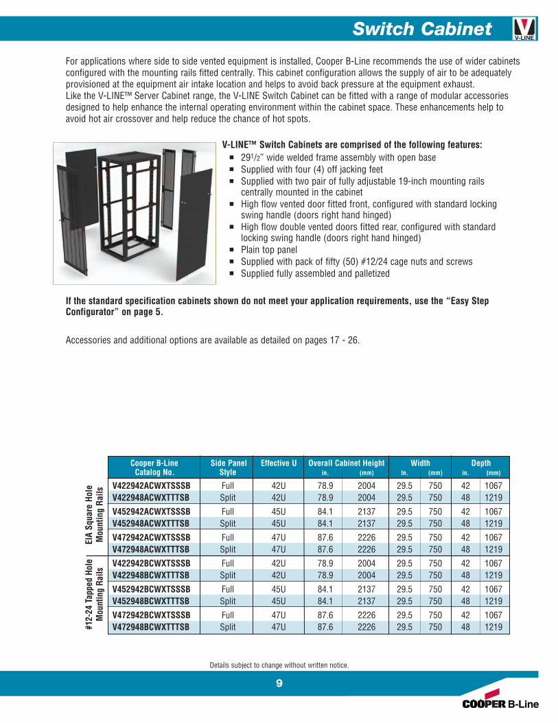
For applications where side to side vented equipment is installed, Cooper B-Line recommends the use of wider cabinetsconfigured with the mounting rails fitted centrally. This cabinet configuration allows the supply of air to be adequatelyprovisioned at the equipment air intake location and helps to avoid back pressure at the equipment exhaust.Like the V-LINE™ Server Cabinet range, the V-LINE Switch Cabinet can be fitted with a range of modular accessoriesdesigned to help enhance the internal operating environment within the cabinet space. These enhancements help toavoid hot air crossover and help reduce the chance of hot spots.
V-LINE™ Switch Cabinets are comprised of the following features:n 291/2” wide welded frame assembly with open basen Supplied with four (4) off jacking feetn Supplied with two pair of fully adjustable 19-inch mounting rails
centrally mounted in the cabinetn High flow vented door fitted front, configured with standard locking
swing handle (doors right hand hinged)n High flow double vented doors fitted rear, configured with standard
locking swing handle (doors right hand hinged)n Plain top paneln Supplied with pack of fifty (50) #12/24 cage nuts and screwsn Supplied fully assembled and palletized
If the standard specification cabinets shown do not meet your application requirements, use the “Easy StepConfigurator” on page 5.
Accessories and additional options are available as detailed on pages 17 - 26.
Details subject to change without written notice.
Cooper B-Line Side Panel Effective U Overall Cabinet Height Width DepthCatalog No. Style in. (mm) In. (mm) in. (mm)
V422942ACWXTSSSB Full 42U 78.9 2004 29.5 750 42 1067V422948ACWXTTTSB Split 42U 78.9 2004 29.5 750 48 1219
V452942ACWXTSSSB Full 45U 84.1 2137 29.5 750 42 1067V452948ACWXTTTSB Split 45U 84.1 2137 29.5 750 48 1219
V472942ACWXTSSSB Full 47U 87.6 2226 29.5 750 42 1067V472948ACWXTTTSB Split 47U 87.6 2226 29.5 750 48 1219
V422942BCWXTSSSB Full 42U 78.9 2004 29.5 750 42 1067V422948BCWXTTTSB Split 42U 78.9 2004 29.5 750 48 1219
V452942BCWXTSSSB Full 45U 84.1 2137 29.5 750 42 1067V452948BCWXTTTSB Split 45U 84.1 2137 29.5 750 48 1219
V472942BCWXTSSSB Full 47U 87.6 2226 29.5 750 42 1067V472948BCWXTTTSB Split 47U 87.6 2226 29.5 750 48 1219
EIA
Squa
re H
ole
Mou
ntin
g Ra
ils#1
2-24
Tap
ped
Hole
Mou
ntin
g Ra
ils
10
Co-Locate Cabinet
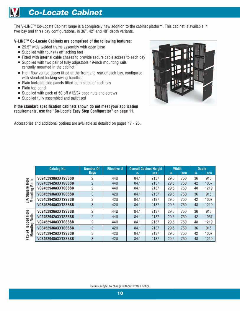
The V-LINE™ Co-Locate Cabinet range is a completely new addition to the cabinet platform. This cabinet is available intwo bay and three bay configurations, in 36”, 42” and 48” depth variants.
V-LINE™ Co-Locate Cabinets are comprised of the following features:n 29.5” wide welded frame assembly with open basen Supplied with four (4) off jacking feetn Fitted with internal cable chases to provide secure cable access to each bayn Supplied with two pair of fully adjustable 19-inch mounting rails
centrally mounted in the cabinetn High flow vented doors fitted at the front and rear of each bay, configured
with standard locking swing handlesn Plain lockable side panels fitted both sides of each bayn Plain top paneln Supplied with pack of 50 off #12/24 cage nuts and screwsn Supplied fully assembled and palletized
If the standard specification cabinets shown do not meet your applicationrequirements, use the “Co-Locate Easy Step Configurator” on page 11.
Accessories and additional options are available as detailed on pages 17 - 26.
Details subject to change without written notice.
Catalog No. Number Of Effective U Overall Cabinet Height Width DepthBays in. (mm) In. (mm) in. (mm)
VC2452938AXXTSSSSB 2 44U 84.1 2137 29.5 750 36 915VC2452942AXXTSSSSB 2 44U 84.1 2137 29.5 750 42 1067VC2452948AXXTSSSSB 2 44U 84.1 2137 29.5 750 48 1219
VC3452936AXXTSSSSB 3 42U 84.1 2137 29.5 750 36 915VC3452942AXXTSSSSB 3 42U 84.1 2137 29.5 750 42 1067VC3452948AXXTSSSSB 3 42U 84.1 2137 29.5 750 48 1219
VC2452936AXXTSSSSB 2 44U 84.1 2137 29.5 750 36 915VC2452942AXXTSSSSB 2 44U 84.1 2137 29.5 750 42 1067VC2452948AXXTSSSSB 2 44U 84.1 2137 29.5 750 48 1219
VC3452936AXXTSSSSB 3 42U 84.1 2137 29.5 750 36 915VC3452942AXXTSSSSB 3 42U 84.1 2137 29.5 750 42 1067VC3452948AXXTSSSSB 3 42U 84.1 2137 29.5 750 48 1219
EIA
Squa
re H
ole
Mou
ntin
g Ra
ils#1
2-24
Tap
ped
Hole
Mou
ntin
g Ra
ils

Co-Locate Easy Step Configurator
11
Details subject to change without written notice.
VC
2
45
29
42
A
V-LINE™ Co-LocateCabinet
Compartments
Cabinet Height
Cabinet Width
Cabinet Depth
Mounting RailType
Options
2 = 2-Bay (22U per compartment) 3 = 3-Bay (14U per compartment)
45U
29 = 291/2”
36 = 36” 42 = 42” 48 = 48”
A = 19” Square Holes Rails only available centered onB = 19” #12-24 Tapped Holes co-locate cabinets
V
X
S
S
S
V
B
Front Door
Rear Door
Locking Options
Left Hand (LH) Side Panel Configuration
Right Hand (RH) Side Panel Configuration
Top PanelConfiguration
Finish
V = High Flow Vented LHW = High Flow Vented RH A = Acrylic LHX = High Flow Vented Split* B = Acrylic RHS = Solid LHT = Solid RHN = None
S = Swing Handle (single point) D = Combo Handle (3-point)C = Combo Handle (single point) P = i-PAL Handle (2-point)T = Swing Handle (3-point) N = None
S = SolidV = VentedN = None
S = Solid Top 2 = 210 CFM Fan Top 1 = 1100 CFM Fan TopV = Vented Top 4 = 420 CFM Fan TopN = None 5 = 550 CFM Fan Top
A = Gray B = Black
* Only available with T & D locking options.
12
Cabinet Door Options
Details subject to change without written notice.
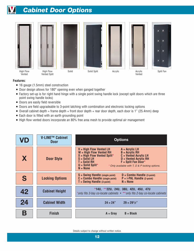
Features:n 16 gauge (1.5mm) steel constructionn Door design allows for 180° opening even when ganged togethern Factory set-up is for right hand hinge with a single point swing handle lock (except split doors which are three
point swing handle locks)n Doors are easily field reversiblen Doors are field upgradeable to 3-point latching with combination and electronic locking optionsn Overall cabinet depth = frame depth + front door depth + rear door depth, each door is 1” (25.4mm) deepn Each door is fitted with an earth grounding pointn High flow vented doors incorporate an 80% free area mesh to provide optimal air management
VD
X
S
42
24
B
V-LINE™ CabinetDoor
Door Style
Locking Options
Cabinet Height
Cabinet Width
Finish
Options
V = High Flow Vented LH A = Acrylic LHW = High Flow Vented RH B = Acrylic RHX = High Flow Vented Split* C = Vented Acrylic LHS = Solid LH D = Vented Acrylic RHT = Solid RH F = Split Fan Door*U = Solid Split*N = None
S = Swing Handle (single point) D = Combo Handle (3-point)C = Combo Handle (single point) P = i-PAL Handle (2-point)T = Swing Handle (3-point) N = None
*14U, **22U, 24U, 38U, 42U, 45U, 47U*only fits 3-bay co-locate cabinets • **only fits 2-bay co-locate cabinets
24 = 24” 29 = 291/2”
A = Gray B = Black
* Only available with T, D & P locking options.
High FlowVented
High FlowVented Split
Solid Solid Split Acrylic AcrylicVented
Split Fan
Cabinet Door Options
13
Details subject to change without written notice.
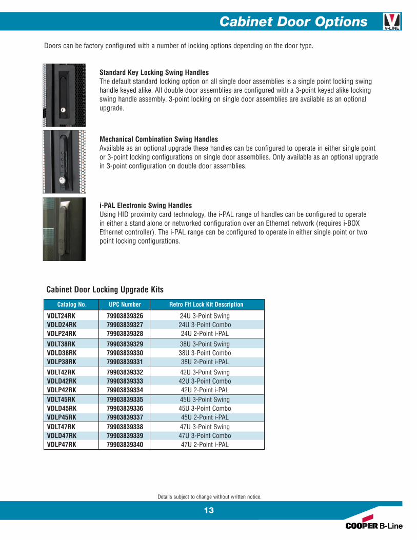
Standard Key Locking Swing HandlesThe default standard locking option on all single door assemblies is a single point locking swinghandle keyed alike. All double door assemblies are configured with a 3-point keyed alike lockingswing handle assembly. 3-point locking on single door assemblies are available as an optionalupgrade.
Mechanical Combination Swing HandlesAvailable as an optional upgrade these handles can be configured to operate in either single pointor 3-point locking configurations on single door assemblies. Only available as an optional upgradein 3-point configuration on double door assemblies.
i-PAL Electronic Swing HandlesUsing HID proximity card technology, the i-PAL range of handles can be configured to operatein either a stand alone or networked configuration over an Ethernet network (requires i-BOXEthernet controller). The i-PAL range can be configured to operate in either single point or twopoint locking configurations.
Doors can be factory configured with a number of locking options depending on the door type.
Catalog No. UPC Number Retro Fit Lock Kit Description
VDLT24RK 79903839326 24U 3-Point SwingVDLD24RK 79903839327 24U 3-Point ComboVDLP24RK 79903839328 24U 2-Point i-PAL
VDLT38RK 79903839329 38U 3-Point SwingVDLD38RK 79903839330 38U 3-Point ComboVDLP38RK 79903839331 38U 2-Point i-PAL
VDLT42RK 79903839332 42U 3-Point SwingVDLD42RK 79903839333 42U 3-Point ComboVDLP42RK 79903839334 42U 2-Point i-PALVDLT45RK 79903839335 45U 3-Point SwingVDLD45RK 79903839336 45U 3-Point ComboVDLP45RK 79903839337 45U 2-Point i-PALVDLT47RK 79903839338 47U 3-Point SwingVDLD47RK 79903839339 47U 3-Point ComboVDLP47RK 79903839340 47U 2-Point i-PAL
Cabinet Door Locking Upgrade Kits

14
Cabinet Side Panel Options
Details subject to change without written notice.
Features:n Available in solid or vented and split configurationsn 17 gauge (1.4mm) steel constructionn Lift off design for easy equipment accessn Locking feature with twin side 1/4 turn latchesn Recessed lock to allow for panels to be installed between ganged enclosuresn Fitted with an earth grounding point
VP
X
42
24
B
V-LINE™ CabinetSide Panel
Side Panel Style
Cabinet Height
Cabinet Depth
Finish
Options
S = Solid Full Height*T = Solid Split**V = Vented Full Height*W = Vented Split**N = None
*14U, **22U, 24U, 38U, 42U, 45U, 47U*only fits 3-bay co-locate cabinets • ** only fits 2-bay co-locate cabinets
24 = 24” 30 = 30” *36 = 24” *42 = 42” *48 = 48”*Co-locate cabinets only available in these depths
A = Gray B = Black
* Not available on 42U x 48”,45U x 48”, & 47U x 48” options
** Not available on 24U high options
Solid Full Height Solid Split Vented Full Height Vented Split
Cabinet Bottom Panel Options
15
Details subject to change without written notice.
VB
S
24
30
B
V-LINE™ CabinetBottom Panel
Bottom Panel Style
Cabinet Width
Cabinet Depth
Finish
Options
SP = Solid Panel (4 x OZIP Plates Fitted)FP = Filter Panel (1 x Filter & 1 x OZIP Plate Fitted)*
* Not available on 24” deep options
24 = 24” 29 = 291/2”
24 = 24” 30 = 30” 36 = 36” 42 = 42” 48 = 48”
A = Gray B = Black
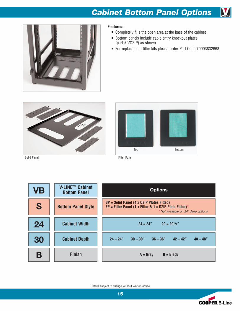
Features:n Completely fills the open area at the base of the cabinetn Bottom panels include cable entry knockout plates
(part # VOZIP) as shownn For replacement filter kits please order Part Code 79903832668
Solid Panel Filter Panel
Top Bottom

16
Cabinet Top Panel Options
Features:n Secure installation via 24” (610mm) mounting rails
welded to top of framen Available in solid top, vented top or fan tops for increased
airflown Fan tops can hold up to four 105 CFM fans or
two 550 CFM fans and are configured 110 VAC
VTP
S
A
B
V-LINE™ CabinetTop Panel
Top Panel Style
Cabinet SizeConfiguration
Finish
Options
S = Solid Top 2 = 210 CFM Fan Top 1 = 1100 CFM Fan Top*V = Vented Top 4 = 420 CFM Fan Top * Not available onN = None 5 = 550 CFM Fan Top 24” deep options
A = To suit cabinet 24” wide x 30”, 36”, 42”, or 48” DeepB = To suit cabinet 291/2” wide x 30”, 36”, 42”, or 48” Deep
C = To suit cabinet 24” wide x 24” DeepD = To suit cabinet 291/2” wide x 24” Deep
B = Black G = Gray
Details subject to change without written notice.
Solid
550 CFM Fan
Vented
1100 CFM Fan
Cabinet Accessories
17
Details subject to change without written notice.
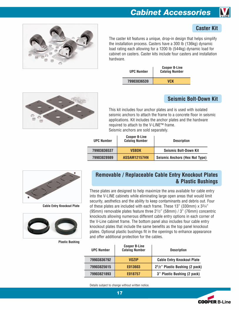
Caster Kit
The caster kit features a unique, drop-in design that helps simplifythe installation process. Casters have a 300 lb (136kg) dynamicload rating each allowing for a 1200 lb (544kg) dynamic load forcabinet on casters. Caster kits include four casters and installationhardware.
Seismic Bolt-Down Kit
This kit includes four anchor plates and is used with isolatedseismic anchors to attach the frame to a concrete floor in seismicapplications. Kit includes the anchor plates and the hardwarerequired to attach to the V-LINE™ frame.Seismic anchors are sold separately.
Removable / Replaceable Cable Entry Knockout Plates& Plastic Bushings
These plates are designed to help maximize the area available for cable entryinto the V-LINE cabinets while eliminating large open areas that would limitsecurity, aesthetics and the ability to keep contaminants and debris out. Fourof these plates are included with each frame. These 13” (330mm) x 33/4”(95mm) removable plates feature three 21/2” (58mm) / 3” (76mm) concentricknockouts allowing numerous different cable entry options in each corner ofthe V-Line cabinet frame. The bottom panel also includes four cable entryknockout plates that include the same benefits as the top panel knockoutplates. Optional plastic bushings fit in the openings to enhance appearanceand offer additional protection for the cables.
Cooper B-LineUPC Number Catalog Number
79903836539 VCK
Cooper B-LineUPC Number Catalog Number Description
79903836537 VSBDK Seismic Bolt-Down Kit
79903828989 ASSAM12157HN Seismic Anchors (Hex Nut Type)
Cooper B-LineUPC Number Catalog Number Description
79903836792 VOZIP Cable Entry Knockout Plate
79903825615 E013603 21/2” Plastic Bushing (2 pack)
79903821893 E018757 3” Plastic Bushing (2 pack)
Plastic Bushing
Cable Entry Knockout Plate
18
Cabinet Accessories
Details subject to change without written notice.
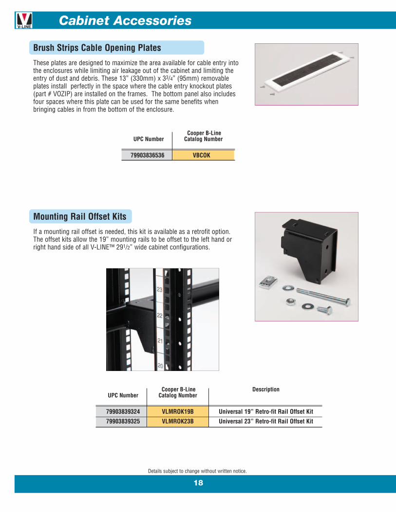
Mounting Rail Offset Kits
If a mounting rail offset is needed, this kit is available as a retrofit option.The offset kits allow the 19” mounting rails to be offset to the left hand orright hand side of all V-LINE™ 291/2” wide cabinet configurations.
Cooper B-Line DescriptionUPC Number Catalog Number
79903839324 VLMROK19B Universal 19” Retro-fit Rail Offset Kit
79903839325 VLMROK23B Universal 23” Retro-fit Rail Offset Kit
Brush Strips Cable Opening Plates
These plates are designed to maximize the area available for cable entry intothe enclosures while limiting air leakage out of the cabinet and limiting theentry of dust and debris. These 13” (330mm) x 33/4” (95mm) removableplates install perfectly in the space where the cable entry knockout plates(part # VOZIP) are installed on the frames. The bottom panel also includesfour spaces where this plate can be used for the same benefits whenbringing cables in from the bottom of the enclosure.
Cooper B-LineUPC Number Catalog Number
79903836536 VBCOK
Cabinet Accessories
19
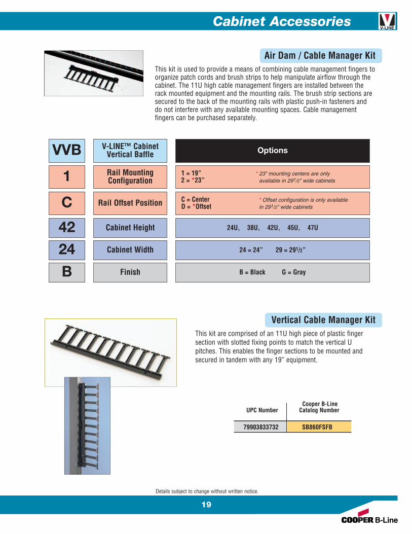
VVB
1
42
24
B
V-LINE™ CabinetVertical Baffle
Rail MountingConfiguration
Cabinet Height
Cabinet Width
Finish
Options
1 = 19” * 23” mounting centers are only2 = *23” available in 291/2” wide cabinets
C Rail Offset Position C = Center * Offset configuration is only availableD = *Offset in 291/2” wide cabinets
24U, 38U, 42U, 45U, 47U
24 = 24” 29 = 291/2”
B = Black G = Gray
Air Dam / Cable Manager KitThis kit is used to provide a means of combining cable management fingers toorganize patch cords and brush strips to help manipulate airflow through thecabinet. The 11U high cable management fingers are installed between therack mounted equipment and the mounting rails. The brush strip sections aresecured to the back of the mounting rails with plastic push-in fasteners anddo not interfere with any available mounting spaces. Cable managementfingers can be purchased separately.
Vertical Cable Manager KitThis kit are comprised of an 11U high piece of plastic fingersection with slotted fixing points to match the vertical Upitches. This enables the finger sections to be mounted andsecured in tandem with any 19” equipment.
Cooper B-LineUPC Number Catalog Number
79903833732 SB860FSFB
Details subject to change without written notice.

20
Cabinet Accessories
Details subject to change without written notice.
Cabinet Ganging KitThe V-LINE™ Cabinet frame has been updated to include a simplerganging facility. Each cabinet frame has knock-outs in the sidemembers, allowing frames to be butted side by side, and simplyfastened together. This feature allows the cabinets to be gangedwith or without side panels fitted.Ganging kits are include six (6) bolts and six (6) flange nuts
Cabinet Earthing Kit
The universal cabinet earthing kit includes the appropriate numberof earth leads and hardware, which helps provide the appropriateearth continuity. Throughout, the frame and cladding componentsare in compliance with EN60950 Clause 2.5.11. For V-LINEco-locate cabinet assemblies, one earth kit will be required per bayconfiguration.
Cooper B-LineUPC Number Catalog Number
79903839125 VLGK
Cooper B-LineUPC Number Catalog Number
79903833081 EEK6
Screws & Cage NutsAll part numbers are packaged and sold in bags of 100pieces
Screws
Screws
Cage Nuts
Cage Nuts
UPC Cooper B-LineNumber Catalog Number Description Finish
79903821311 E2MA1032PHMS100 #10-32 Phillips Clear Zinc79903821470 E2MA1224PHMS100 #12-24 Phillips Clear Zinc79903830134 E2MAM6PHMS100 M6 Phillips Yellow Zinc79903829784 E2MACN1032100 #10-32 Phillips Clear Zinc79903814665 E2MACN1224100 #12-24 Phillips Clear Zinc79903830133 E2MACNM6100 M6 Phillips Yellow Zinc

Cabinet Accessories
21
Developed to provide enhanced vertical cable management, these new cable managerkits have been designed specifically to complement the 291/2” V-LINE™ cabinetplatform. The 23/4” wide units can be fitted on the left hand and right hand side of thecabinets with the mounting rails positioned centrally. The 51/2” wide units can only befitted on the left or right to match the optional mounting rail offset configurations.
n Can factory fitted or easily retro-fitted in the fieldn Split doors for improved operation and easy removaln Integral cable tie lances and multiple mounting points for twist and lock cable
management armsn Steel material with UL 94V-0 black plastic componentsn Black RAL 9005 epoxy polyester powder coat paint finish
Designed to span between front and rear mounted enhanced vertical cable managers,these cable troughs simply clip into the rear of the vertical manager in line with thecable pass through.
n Can factory fitted or easily retro-fitted in the fieldn Available in two widthsn Available in varying depth rangesn Black RAL 9005 epoxy polyester powder coat paint finish
Details subject to change without written notice.
UPC Number Cooper B-Line Cabinet Unit Cabinet Width OffsetCatalog Number Height in. (mm)
79903839187 VVCMC24FB 24U79903839189 VVCMC38FB 38U79903838355 VVCMC42FB 42U 23/4” 70 Center79903839191 VVCMC45FB 45U79903838356 VVCMC47FB 47U
79903839188 VVCMS24FB 24U79903839190 VVCMS38FB 38U79903838357 VVCMS42FB 42U 51/2” 140 Offset Left or Right79903839192 VVCMS45FB 45U79903838358 VVCMS47FB 47U
UPC Cooper B-Line Mim. Depth Max. Depth To Suit VerticalNumber Catalog Number Adjustment Adjustment Manager Configuration
in. (mm) in. (mm) in. (mm)
79903838391 ACCT070400B 101/4” 260 157/8” 403 2.785” 7079903838392 ACCT070590B 143/8” 365 233/8” 594 2.785” 7079903838393 ACCT070890B 181/8” 460 311/8” 70 2.785” 7079903838397 VCT5501600B 101/4” 260 157/8” 403 5.5” 14079903838398 VCT5502350B 143/8” 365 233/8” 594 5.5” 14079903838399 VCT5503525B 181/8” 460 311/8” 70 5.5” 140
Enhanced Vertical Cable Manager Kit
Horizontal Cable Trough Kit
22
Cabinet Accessories
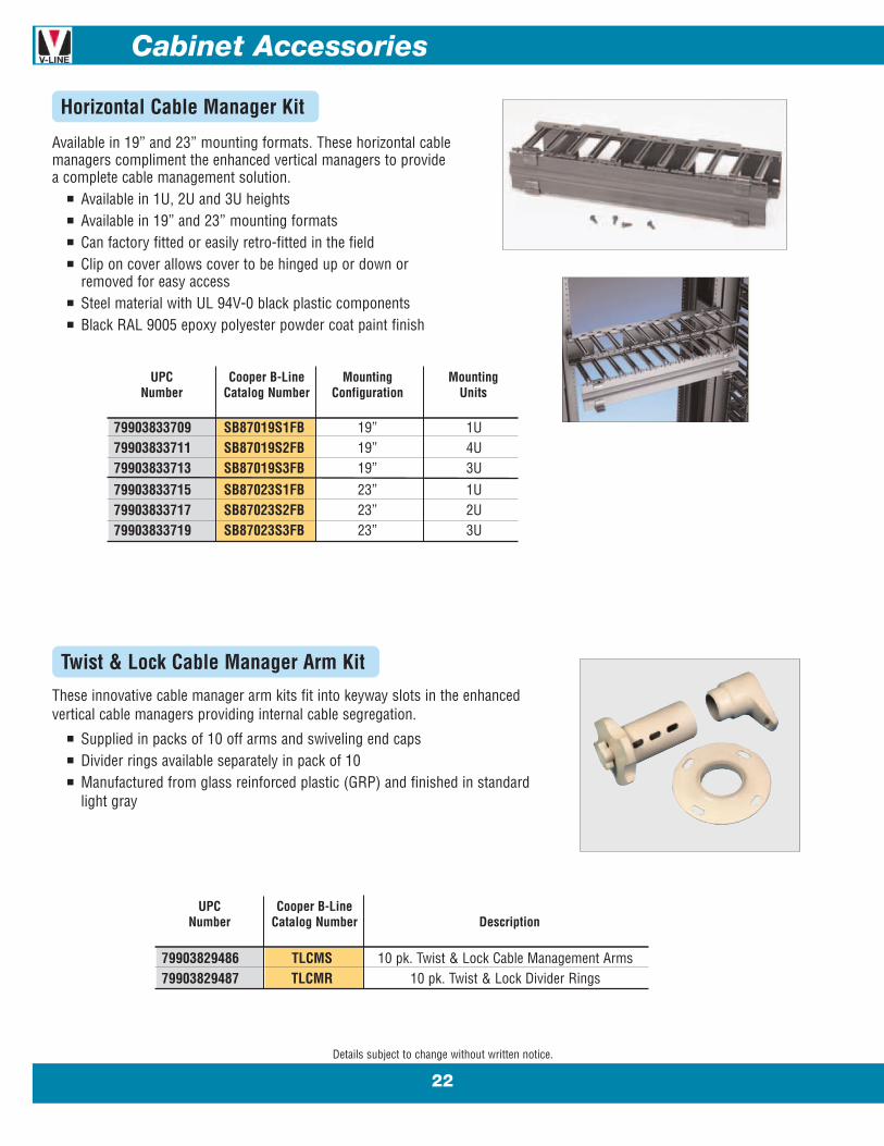
Available in 19” and 23” mounting formats. These horizontal cablemanagers compliment the enhanced vertical managers to providea complete cable management solution.
n Available in 1U, 2U and 3U heightsn Available in 19” and 23” mounting formatsn Can factory fitted or easily retro-fitted in the fieldn Clip on cover allows cover to be hinged up or down or
removed for easy accessn Steel material with UL 94V-0 black plastic componentsn Black RAL 9005 epoxy polyester powder coat paint finish
These innovative cable manager arm kits fit into keyway slots in the enhancedvertical cable managers providing internal cable segregation.
n Supplied in packs of 10 off arms and swiveling end capsn Divider rings available separately in pack of 10n Manufactured from glass reinforced plastic (GRP) and finished in standard
light gray
Details subject to change without written notice.
Horizontal Cable Manager Kit
Twist & Lock Cable Manager Arm Kit
UPC Cooper B-Line Mounting MountingNumber Catalog Number Configuration Units
79903833709 SB87019S1FB 19” 1U79903833711 SB87019S2FB 19” 4U79903833713 SB87019S3FB 19” 3U79903833715 SB87023S1FB 23” 1U79903833717 SB87023S2FB 23” 2U79903833719 SB87023S3FB 23” 3U
UPC Cooper B-LineNumber Catalog Number Description
79903829486 TLCMS 10 pk. Twist & Lock Cable Management Arms79903829487 TLCMR 10 pk. Twist & Lock Divider Rings
Cabinet Accessories
23
Details subject to change without written notice.
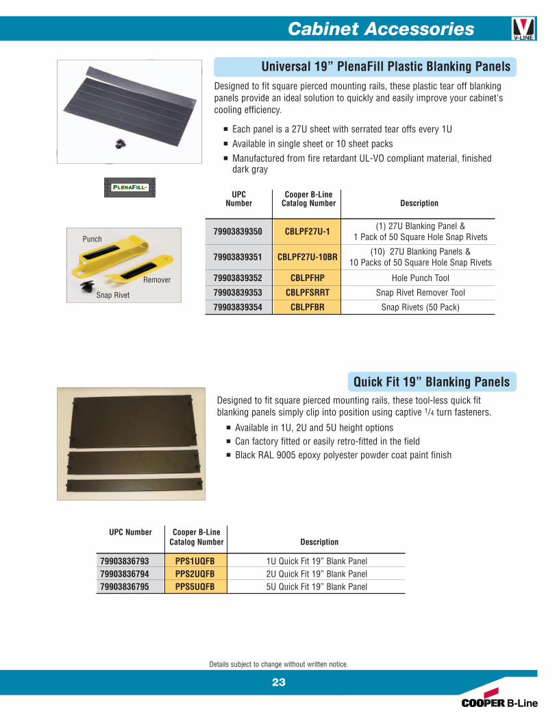
Universal 19” PlenaFill Plastic Blanking Panels Designed to fit square pierced mounting rails, these plastic tear off blankingpanels provide an ideal solution to quickly and easily improve your cabinet'scooling efficiency.
n Each panel is a 27U sheet with serrated tear offs every 1Un Available in single sheet or 10 sheet packsn Manufactured from fire retardant UL-VO compliant material, finished
dark gray
UPC Cooper B-LineNumber Catalog Number Description
79903839350 CBLPF27U-1 (1) 27U Blanking Panel &1 Pack of 50 Square Hole Snap Rivets
79903839351 CBLPF27U-10BR (10) 27U Blanking Panels &10 Packs of 50 Square Hole Snap Rivets
79903839352 CBLPFHP Hole Punch Tool
79903839353 CBLPFSRRT Snap Rivet Remover Tool
79903839354 CBLPFBR Snap Rivets (50 Pack)
Punch
Remover
Snap Rivet
Designed to fit square pierced mounting rails, these tool-less quick fitblanking panels simply clip into position using captive 1/4 turn fasteners.
n Available in 1U, 2U and 5U height optionsn Can factory fitted or easily retro-fitted in the fieldn Black RAL 9005 epoxy polyester powder coat paint finish
Quick Fit 19” Blanking Panels
UPC Number Cooper B-LineCatalog Number Description
79903836793 PPS1UQFB 1U Quick Fit 19” Blank Panel79903836794 PPS2UQFB 2U Quick Fit 19” Blank Panel79903836795 PPS5UQFB 5U Quick Fit 19” Blank Panel

24
Cabinet Accessories
Cable Guide KitCable guides are designed to install directly on mounting rails for vertical cablemanagement. Guide size is 4” (101mm) x 2” (51mm). Guides have a powder coatfinish and include mounting hardware.
Narrow Cable Hoop KitNarrow cable hoops are designed to maximize cable managementin a 24” (600mm) wide cabinet. Each hoop has 2.4 in.2 (1550mm2)of internal cable management space. Narrow cable hoops install onthe mounting rail between the mounting rail and side panel. Installsin 1U. n Standard finish is yellow zinc plated and clear passivate (silver).
UPC Cooper B-LineNumber Catalog Number
79903816101 E2MACMR3BLP
UPC Cooper B-LineNumber Catalog Number
79903829481 ACH6Cable Hoop
installed on rail
Details subject to change without written notice.
These blanking panels are designed to be used in to aid thermal managementin applications where equipment cools side to side. These adjustable depthblanking panels clip into the side mount facility on the V-LINE™ cabinetmounting rails, simply clipping into place using the tool-less quick fit captive1/4 turn fasteners.
n Available in 1U, 2U and 5U height optionsn Can factory fitted or easily retro-fitted in the fieldn Black RAL 9005 epoxy polyester powder coat paint finish
Adjustable Depth Side Blanking Panels
UPC No. Cooper B-Line Mounting Depth Range Blank PanelCatalog No. Minimum Maximum Description
in. (mm) in. (mm)
79903839341 SESBP1U3QFB 10.4” 264 14.4” 366 1U Quick Fit 19”79903839342 SESBP1U4QFB 14.8” 376 18.8” 478 1U Quick Fit 19”79903839343 SESBP1U5QFB 19.2” 488 23.2” 590 1U Quick Fit 19”79903839344 SESBP2U3QFB 10.4” 264 14.4” 366 2U Quick Fit 19”79903839345 SESBP2U4QFB 14.8” 376 18.8” 478 2U Quick Fit 19”79903839346 SESBP2U5QFB 19.2” 488 23.2” 590 2U Quick Fit 19”79903839347 SESBP5U3QFB 10.4” 264 14.4” 366 5U Quick Fit 19”79903839348 SESBP5U4QFB 14.8” 376 18.8” 478 5U Quick Fit 19”79903839349 SESBP5U5QFB 19.2” 488 23.2” 590 5U Quick Fit 19”
Cabinet Accessories
25
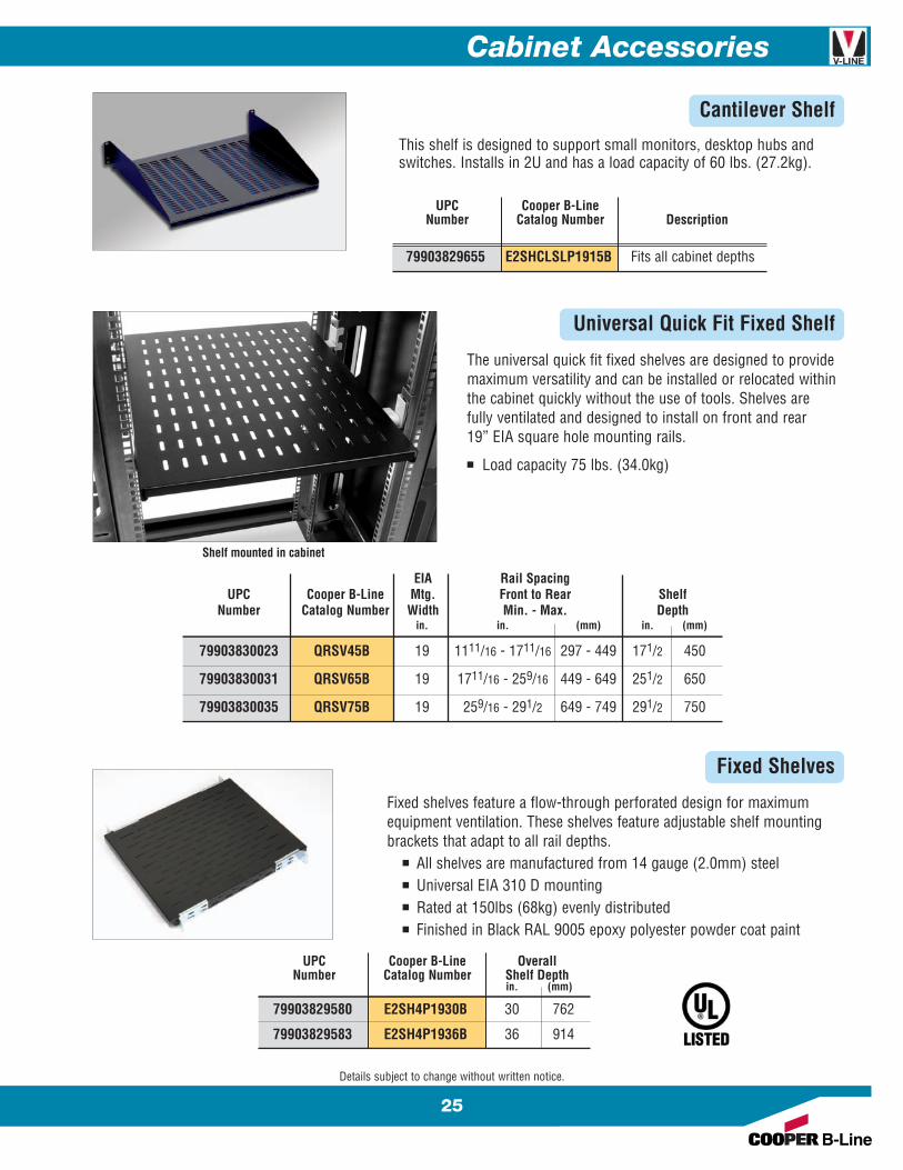
This shelf is designed to support small monitors, desktop hubs andswitches. Installs in 2U and has a load capacity of 60 lbs. (27.2kg).
UPC Cooper B-LineNumber Catalog Number Description
79903829655 E2SHCLSLP1915B Fits all cabinet depths
Cantilever Shelf
Universal Quick Fit Fixed Shelf
The universal quick fit fixed shelves are designed to providemaximum versatility and can be installed or relocated withinthe cabinet quickly without the use of tools. Shelves arefully ventilated and designed to install on front and rear19” EIA square hole mounting rails.
n Load capacity 75 lbs. (34.0kg)
Fixed Shelves
Fixed shelves feature a flow-through perforated design for maximumequipment ventilation. These shelves feature adjustable shelf mountingbrackets that adapt to all rail depths.
n All shelves are manufactured from 14 gauge (2.0mm) steeln Universal EIA 310 D mountingn Rated at 150lbs (68kg) evenly distributedn Finished in Black RAL 9005 epoxy polyester powder coat paint
EIA Rail SpacingUPC Cooper B-Line Mtg. Front to Rear Shelf
Number Catalog Number Width Min. - Max. Depthin. in. (mm) in. (mm)
79903830023 QRSV45B 19 1111/16 - 1711/16 297 - 449 171/2 450
79903830031 QRSV65B 19 1711/16 - 259/16 449 - 649 251/2 650
79903830035 QRSV75B 19 259/16 - 291/2 649 - 749 291/2 750
Shelf mounted in cabinet
Details subject to change without written notice.
UPC Cooper B-Line OverallNumber Catalog Number Shelf Depth
in. (mm)
79903829580 E2SH4P1930B 30 762
79903829583 E2SH4P1936B 36 914

26
Cabinet Accessories
Universal Quick Fit Sliding ShelvesThe universal quick fit sliding shelf is easy to install and providesquick access to your equipment. This shelf is fully ventilated anddesigned to install on front and rear 19” EIA square hole mountingrails. Each shelf has a load capacity of 275 lbs. (125kg).
Sliding ShelvesLike the fixed shelves, these sliding shelves feature a flow-throughperforated design for maximum equipment ventilation. They also featureadjustable shelf mounting brackets that adapt to all rail depths.
n All shelves are manufactured from 14 gauge (2.0mm) steeln Universal EIA 310 D mountingn Rated at 150lbs (68kg) evenly distributedn Black RAL 9005 epoxy polyester powder coat paint finish
Details subject to change without written notice.
(closed)
(extended)
UPC Cooper B-Line OverallNumber Catalog Number Shelf Depth
in. (mm)
79903829619 E2SHSS1930B 30 762
79903829621 E2SHSS1936B 36 914
Shelf, closed
Shelf, extended
Mounting bracketper IEC 917-2-1
EIA Rail SpacingUPC Cooper B-Line Mtg. Front to Rear Shelf
Number Catalog Number Width Min. - Max. Depthin. in. (mm) in. (mm)
79903829731 QRTSV45B 19 147/8 - 203/16 363 - 513 171/2 450
79903829732 QRTSV65B 19 203/16 - 261/8 513 - 663 251/2 650
79903829733 QRTSV75B 19 261/8 - 32 663 - 812 291/2 750
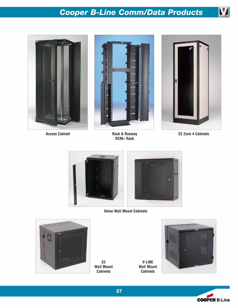
Cooper B-Line Comm/Data Products
27
Rack & RunwayRCM+ Rack
E2 Zone 4 CabinetsAccess Cabinet
Value Wall Mount Cabinets
E2Wall Mount
Cabinets
V-LINEWall Mount
Cabinets
Other Cooper B-Line Product Lines
Strut Systems (Bolted Framing)Cable Tray SystemsElectrical EnclosuresElectronic EnclosuresPipe Hanger & Support SystemsSpring Steel FastenersCable Runway & Relay Racks (CommData)Meter Mounting & Distribution EquipmentAnchors
VLNGCD-10
© 2010 Cooper B-Line, Inc. Printed in U.S.A. 25110
SYSTEMS THAT MAKE SENSE
“ BB --VV OOCCAALLSS MM“ BB-- VVOO CCAALLSS MM
Questions, Comments, Suggestions?
with Cooper B-Line”Voice Of the Customer...Actively Listening
“ BB-- VVOO CCAALLSS MM
Cooper B-Line509 West Monroe StreetHighland, IL 62249Phone: 800-851-7415Fax: 618-654-1917
www.cooperbline.com
Cooper Industries, Ltd.600 Travis, Ste. 5800Houston, TX 77002-1001Phone: 713-209-8400www.cooperindustries.com