coommp pa ac - rc aerodyne scale uh-60 (700... · this manual provides the ... *all operators must...
TRANSCRIPT

Coom
Di
U
mp
stribut
CCPM SC
UH‐6
pa
ted by
CALE RC H
60
ac
HELICOPT
ct
TER
torMa
r
nual

Copyright@2013 - Roban Limited – All rights reserved
Compactor 700 Manual – UH‐60
Release 1.0 ‐ April 2013
Roban Limited Dryriver Industrial Zone, Venture Cross Rd. Jiaolian, Wanjiang City District of Dongguan, 523046 Dongguan County (GD) ‐ PRC

Copyright@2013 - Roban Limited – All rights reserved
SPECIFICATIONS
Body length: 1680mm Length incl. rotors: 1850mm Width: 655mm Height: 465mm Main rotor diameter: 1560mm Main blade length: 700mm Tail rotor diameter: 280mm Tail blade length: 105mm Main shaft diameter: 12mm Tail shaft diameter: 5mm Spindle diameter: 8mm Battery compartment: 2x 60x60x180mm Motor:* 1x 750MX 450KV brushless outrunner, 12S capable Speed controller:* 1x 120A brushless, 12S capable Servo:* 3x metal gear cyclic, 1x 9g metal gear tail servo Battery:* 44.4V 5000mAh 35C+ Flight time: 5 minutes Takeoff weight: 9000g Flight Stabilization:* 3 axis flybarless gyro Radio Control:* min. 6 channel with pitch and throttle curves *) Optionally available equipment The Compactor is a high performance radio controlled scale helicopter. Our goal was to create a simple, high performance helicopter, with a minimum of mechanical components and simple maintenance. Please read this user manual carefully, it contains instructions for the correct assembly of the model. Please refer to the web site www.robanmodel.com for updates and other important information. Thank you for your purchase, and have a great time with your Compactor! Roban Limited

Copyright@2013 - Roban Limited – All rights reserved
IMPORTANT NOTES *This radio controlled helicopter is not a toy. *This radio controlled helicopter can be very dangerous. *This radio controlled helicopter is a technically complex device which has to be built and handled very carefully. *This radio controlled helicopter must be built following these instructions. This manual provides the necessary information to correctly assemble the model. It is necessary to carefully follow all the instructions. *Inexperienced pilots must be monitored by expert pilots. *All operators must wear safety glasses and take appropriate safety precautions. *A radio controlled helicopter must only be used in open spaces without obstacles, and far enough from people to minimize the possibility of accidents or of injury to property or persons. *A radio controlled helicopter can behave in an unexpected manner, causing loss of control of the model, making it very dangerous. *Lack of care with assembly or maintenance can result in an unreliable and dangerous model. *Neither Roban Limited nor its agents have any control over the assembly, maintenance and use of this product. Therefore, no responsibility can be traced back to the manufacturer. You hereby agree to release Roban Limited from any responsibility or liability arising from the use of this product.
SAFETY GUIDELINES *Fly only in areas dedicated to the use of model helicopters. *Follow all control procedures for the radio frequency system. *It is necessary that you know your radio system well. Check all functions of the transmitter before every flight. *The blades of the model rotate at a very high speed; be aware of the danger they pose and the damage they may cause. *Never fly in the vicinity of other people.
NOTES FOR ASSEMBLY Please refer to this manual for assembly instructions for this model. Follow the order of assembly indicated. The instructions are divided into chapters, which are structured in a way that each step is based on the work done in the previous step. Changing the order of assembly may result in additional or unnecessary steps. Use thread lockers and retaining compounds as indicated. In general, each bolt or screw that engages with a metal part requires thread lock. Factory pre‐assembled components have been assembled with all the required thread lock and lubricants, and have passed quality control. It is not necessary to disassemble and re‐assemble them. We do not recommend the use of thin cyanoacrylate glue for surface mount of painted parts. The fumes of the curing glue leave white stains on the clear coat, which are hard to remove.

Cop
2
2
3
CO
yright@2013
1 – Tail ge
5 – Tail boo
9 – Tail rot
13 – Tail ser
17 – Fron
21 – Main ro
5 – Tail boom
29 – Scale
33 – Exhaust
ONTENTS:
3 - Roban Lim
ear box
m holder
tor assy
rvo frame
nt gear
tor blades
m supports
cockpit
inner pipe
:
mited – All rig
2
6 – Me
10 –
14 – Ta
22 – L
26 – EV
30 –
3
ghts reserved
2 – Tail tube
echanic main
Main rotor a
ail pushrod g
18 – C-Clips
Long torque
VA boom dis
– Weapon ho
34 - Exhaust
d
nframe
assy
guides
tube
stancer
older
3 – Short t
7 – Mot
11 – Tail se
15 – Landin
19 – Ta
23 – Ta
27 – Tail ro
31 – R
35 – Ta
torque tube
or pulley
ervo Holder
ng gear bolts
ail gear
ail tube
otor blades
Rockets
ail wing
8 – S
12 – To
16
20
24 –
2
3
3
4 – Ball links
Short tail serv
orque tube b
6 – Center ge
– Gear supp
Long tail ser
28 – Scale Pa
32 – Fuel tan
36 – Tail win
s
vo rod
bearings
ear
ports
rvo rod
art
ks
ng

Cop
4
5
5
6
Rem
yright@2013
37 – Plast
1 – Screw M
45 – L bra
49 – Ball lin
3 – Screw M
57 – Scale ac
61 – Scale a
65 – LED
69 – LED ligh
marks:
3 - Roban Lim
tic bolts
M3x14 4pcs
ackets
nks 3pcs
M4x25 3pcs
cc. D 2pcs
cc. H 1pc
light B
t controller
UH-60 BlackSH-60 SeahaHH-60 Coas
mited – All rig
38
42 – S
46 – S
5
54 –
58 – S
62 –
66
7
khawk does nawk does notguard does
ghts reserved
8 – Windshie
crew A1.7x6
crew M4x10
50 – Nut M2
Scale acc. A
Scale acc. E
Scale acc. I 2
6 – LED light
0 – Decal Se
not contain pot contain pa not contain
d
ld
6 4pcs
0 4pcs
51
A 1pc
2pcs
2pcs
C
6
et
parts 16 and rts 16 and 36 parts 17, 36,
39 – Screw A
43 – Washe
47 – Screw
1 – Wooden
55 – Scale
59 – Scale
63 – Scale J
67 – Prolong
35. 6. , 30 to 34, 54
A3x16 16pcs
er 3x8 8pcs
M3x10 6pcs
washers 8p
acc. B 2pcs
acc. F 1pc
J acc. B 1pc
ing wire 4pc
4, 55, 56, an
s 40 –
44 – W
s
48 – S
cs 52 – S
56 –
60 –
64
s 68
d 58 to 62.
Screw A2x8
Washer 4x10
Self lock nut
Screw A3x10
– Scale acc. C
Scale acc. G
4 – LED light
8 – LED light
8 8pcs
0 7pcs
M 4pcs
0 6pcs
C 1pc
G 2pcs
t A
cap

AD*Elec 10S pin*Spe mi*Bat*1 fl*Rad*3 cy*1 ta*6 ch Insid InsidBox Box Box Bag Bag 2Bag 3Bag 4Bag 5Bag 6Bag 7Bag 8Bag 9Bag Bag Bag MastMastMast
DDITIONActric Motor: S‐12S – 400‐6nion shaft diameed controllernimum 120A tteries: 10‐12Sybarless 3 axidio power systyclic servos ail rotor servohannel radio c
de the main
de the main b1: Main Fram2: Boom, Blad3: Scale Cockp1: Tail fin rod 2: Position lig3: Scale fitting4: Tail boom a5: Fuselage sc6: Mechanica7: Tail Wings 8: Belt drive p9: Battery tray10: EVA tail d11: Footrests 12: Front winter Pack 4: Froter Pack 5: Tater Pack 6: Alu
AL COMPO
600Kv, meter 6mm r: to be safe S 4000‐5000ms control unittem
o control system
n box there a
ox: e/Tail Frame/des, Tail bladepit
ht controller gs, screws accessories cale fittings l fittings, scre
pulley y istancer
dow (inside coont scale fuseil boom (all otuminum landi
ONENTS R
mAh , suitable for
m on 2.4 GHz
are:
/Rotorhead es, Rods
ws
ockpit) e (Bag 6 insidether bags) ing gear
REQUIRE
scale flying
e)
D TOOLS, L*Generic plie*Hexagonal d*4mm T‐Wre*5.5mm Sock*8mm Hex fo*Medium thr*Strong retai*Spray lubric*Synthetic gr*Cyanoacryla*Pitch Gauge*Soldering eq
LUBRICANers driver, size 1.5ench ket wrench (foork wrench (foreadlocker (egning compouant (eg. Try‐Frease (eg. Tri‐Fate adhesivee (for set‐up)quipment (for
NTS, ADH
5, 2, 2.5, 3, 4m
or M3 nuts) or M5 nuts) g. Loctite 243)nd (eg. Loctitelow Oil) Flow Syntheti
r motor wiring
HESIVES
mm
) e 648)
c Grease)
g)

Cop
AssPriorinsta
Rem
Instawash
Drill as sh
Insta(40)
yright@2013
sembly Scr to installing allation into th
ove the hatch
all the center her (44) as sho
a 2mm hole, hown.
all the tail booto secure the
3 - Roban Lim
cale Fusethe mechaniche fuselage m
h as shown
landing gear (own.
use screws (5
om as shown. e tail boom.
mited – All rig
elage cs into the fusost of the hel
(16) using scre
52) to install ge
Use washers
ghts reserved
elage, please icopter mech
ew (53) and
ear brackets (
(51) and screw
d
prepare the fanic become
(20)
ws
fuselage accorinaccessible.
Install the tai
Install LED lig
Use screws (5install the lan
Install LED ligprolonging w
rding to the fo
l landing gear
ghts (66) and (
53), shafts (15nding gear (17
ghts (65) on thwires ()w
ollowing steps
r (19) as show
(68) as shown
5), C‐clips(18) 7) as shown.
he right, (64) o
s.
wn using screw
.
and washers
on the left sid
ws (52)
(44) to
e. Use

AssThe Prioradju
SteSlide0000ontoaddit
SteFirst holdthe applyelsewposit(600two (70‐0
sembly Mmechanics arer to the instasted and teste
ep 1 – Rote the rotorhe06) and nylono the main tionally clamp
ep 2 – Taiof all instalers (02‐02006bearings eveny a bit of wise the beartion is reach0UH1‐007), thetail servo hol00096) into th
Mechanicse almost entirallation into ted. After insta
torhead ead onto then nut (70‐00shaft. Use
p up the rotor
l boom l the center 6) into the tanly in the tailubrificant onring is likely thed. Then ine servo rod gulders (70‐0009he tail tube.
s rely preassemthe scale fuseallation into th
e main shaft007) to secutwo screw
r hub onto the
bearings (70ail boom (70‐0l boom. It is nto the tubeto get stuck bstall the cenuides (70‐00098). Install th
mbled and splitelage, the mehe fuselage m
. Use screw re the rotorhs (70‐00008e shaft as show
0‐00100) with00095). Distrirecommendees inner surbefore the conter support 040) and the se tail torque
t up into four echanics havemost of the he
(70‐head ) to wn.
h the bute ed to face, rrect ring
servo tube
sections: rotoe to be entirelicopter mech
Make sure this equally at on the swash
Then insert 00093, 70‐00(70‐00086) vM3x6 (70‐000(70‐00104‐70tail boom cla
orhead, main ely assembledhanic become
he distance be24mm. Finall
hplate’s upper
the tail boom0094). Lock thvia the clamp053) as show0‐00106) on tmp (600UH1‐
frame, tail frad, electronic inaccessible.
etween the bly snap on thr disc uni‐links
m into the tahe tube in plp up and adn. Install the the main fram‐007).
ame and tail tcomponents
all link and the ball links (7s (70‐00030).
ail boom hollace with scredditionally wicarbon suppome and the t
ube. installed,
he L lever 70‐00025)
ders (70‐ew M3x8 ith screw ort beams tail boom

Cop
Ste First boomtail M3xhornrod
SteInstaDepeadjurecogearforce
yright@2013
ep 3 – Tai
of all, moum holders (70servo of you10, washers n and the supp(70‐00103) in
ep 4 – Cycall the three cending on yost the servo tommended tored servos. Tes that may le
3 - Roban Lim
l Servo In
nt the holde0‐00098) usingur choice intoand nylon nuplied uniball. Tnto the four g
clic Servocyclic servos ur servos, yoo the proper io use metal The multi blaead to failure o
mited – All rig
nstallatio
er frame (70‐g screw M3x8o the tail frauts as shown.Then slide theguides. Install
o Installatonto the servu may have tinstallation heservo horns
ade rotor heof plastic com
ghts reserved
n
‐00097) onto8. Then mountame using sc. Install the se tail rotor cothe ball link
tion vo tray as shoto use washeeight. It is stro and only mead can feedmponents.
d
o the t the rews servo ntrol (70‐)
own. rs to ongly metal back
on both endguides evenlyframe onto tshown, but duninstalled alink.
After the selinkage rods distances are1=81mm
ds of the taily along the tathe tail boomdo not use thagain. Snap th
rvos are instlength’s accoe uniball cente
2=112mm
l rotor contrail boom. Them. Lock it withread lock yehe servo con
alled, you wrding to the ser to uniball cem 3=81
ol rod. Distrien install the h the three set, as it has gtrol rod onto
ill have to aschematics beenter: 1mm
ibute the tail rotor screws as got to be o the ball
djust the elow. The

Ste
The set acent
SteIn orof thscrewfastethe pmoto(70‐)
1
ep 5 – Adj
linkages fromat correct lener: 1=35mm
ep 6 – Morder to installhe side framews and acceseners are notpinion pulley or shaft in ord).
just swas
m the L‐Leversngth. Distance
otor and Bl the motor, yes in order toss to the belt t tightened uon the motorder to secure
shplate lin
s to the swashes are uniball
Belt instayou must firsto have accessdrive. Hencepon delivery.r, you have to the pulley w
nkages
h plate have t center to un
allation t disassembles to the moune one side fra. Before instao add a flat towith the set sc
to be niball
e one nting ames alling o the rews
Mount the mthe motor mwire outlet fato the ESC. Thonto the momake sure thpulley, the diUse both tenmustn’t be teAfter installat
motor as showmount (70‐000acing into the hen insert theotor shaft. Behat the piniostance (Fig. 1)sioning screwensioned too ttion of the mo
wn using was066). Make suright directio
e belt pulley inefore you tign is installed ) is at 24.5mm
ws to tension ttight to avoid otor, reassem
shers and scrure to have ton for connectnto the belt anghten the seleveled with
m. the belt driveunnecessary ble the side f
ews onto he motor ting them nd slide it t screws, h the belt
. The belt wear. rames.

Step 7 – Electrical Wiring and Setup
The mechanics have to be fully electrically setup and adjusted prior to installation into the fuselage. As the use of a 12S (44.4V) setup is necessary, we strongly recommend to run the control equipment on a separate 2S Lipo battery and BEC for security reasons. In scale configurations main battery power wires may be longer than on comparable 3D helicopter equipment. As HV ESCs do not necessarily have the main battery ground wire connected to the servo signal ground wire, it may be necessary to create an additional connection between the BEC 2S batteries ground wire and the 12S main battery ground wire. Certain configurations without this ground interconnection have led to a loss of signal at the ESC from the receiver due to EMC effects. The swash plate is a regular 120deg CCPM type, please take your time to adjust all servo travels, center positions – the entire 3 axis gyro – servo – radio setup prior to the installation into the fuselage. A 450KV motor such as the Align 750MX run at app. 80% throttle (hover) shows satisfying results. As space is limited, please make sure you check the dimensions if you intend to use other brand motors. In regards to the gyro setup, we recommend to start with standard values of the 3 axis gyro. Make sure you install the gyro in a way that provides easy access for connecting your programming equipment. As the scale fuselage adds additional inertia to each axis, gyros are normally to be set at a lower gyro gain. All in all, a rigid gyro response does ruin the scale look in flight. Before operating the model check the following points: ‐The direction of servo rotation (including the throttle function) and travels. ‐The direction of effect of the gyro, and the transmitter mixer functions you have programmed. ‐Collective pitch travel (linear travel ‐2/‐3° to +9/+10°)
ATTENTION ! When using the a pitch gauge to adjust correct CP travels, make sure that the gauge lines up with the flat surface of the rotor blade. Many pitch gauges do not show the correct
angle when snapped onto unsymmetric rotor blades! The main rotor blades are not symmetrical. Do not try to fly inverted. ‐ It is permissible to reduce servo travels, but not below 60% (in this case adjust the mechanical linkage); travels should be primarily symmetrical. ‐ Apply collective pitch min. / collective pitch max. and full roll and pitch‐axis commands simultaneously in all directions; rotate the rotor head at the same time, and check that at the extremes of travel no part of the rotor head is obstructed. ‐ The auto‐rotation switch must be assigned, and within easy reach! ‐ When auto‐rotation is selected: throttle position to off, all directions of control and travels as in normal flight, tail rotor to 0° = fixed value. ‐The first few batteries should be flown with the model close to the ground, i.e. no more than about 1 m altitude, until you are confident that there are no defects or errors, and that everything is working faultlessly: ‐ Use your ears critically (!), listening for unusual sounds and vibration, and seek out the problem if you are in any doubt at all! ‐ Don’t listen to anyone standing close by if they try to hurry you into flying the model. ‐ Avoid hovering outside ground effect (hover altitude with a model: approx. 1m, or half the rotor disc diameter): ‐ Hovering requires very high power, and you are completely dependent on the motor: in contrast to most full‐size helicopters, model helicopters have only one (!) power plant.
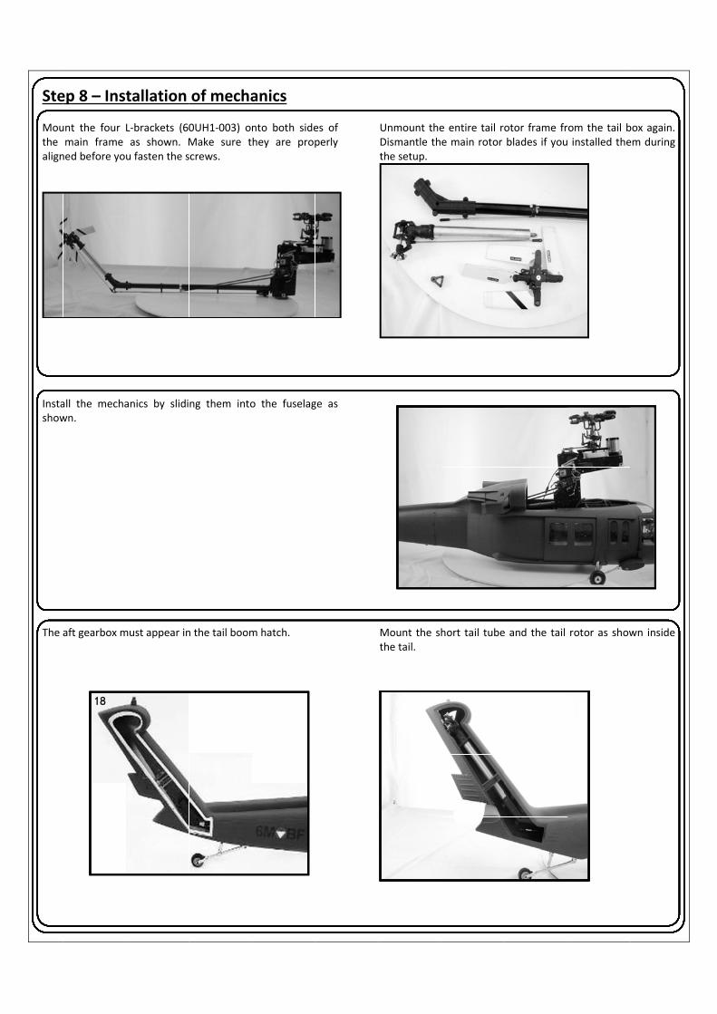
Ste
Mouthe align
Instashow The
ep 8 – Inst
unt the four Lmain frame ned before yo
all the mechawn.
aft gearbox m
18
tallation
L‐brackets (60as shown. Mu fasten the s
anics by slidi
must appear in
of mecha
0UH1‐003) onMake sure tscrews.
ng them into
n the tail boom
anics
nto both sidehey are prop
o the fuselag
m hatch.
es of perly
ge as
Unmount theDismantle ththe setup.
Mount the shthe tail.
e entire tail roe main rotor
hort tail tube
otor frame frblades if you
e and the tail
rom the tail bu installed the
rotor as show
box again. em during
wn inside

Slip to in Nowfuse Insta
the EVA tail dstall it, slot it
w install the mlage.
all the front to
dampener uniwith a knife.
echanics with
op cover as sh
t onto the tai
h 41 and 42 sc
hown.
l boom. In ord
rews into the
der
Install the taishown.
Install the aft
Install the taithe tail rotor
l servo pushro
t top cover as
l boom cover head on the t
ods inside the
shown.
with screws. tail rotor shaf
e tail fuselage
Once installeft.
as
d, install

SteGlue Insta
Insta
ep 9 – Scae the support
all the exhaust
all the weapon
26
ale Fittingrods 37 into t
ts inner unit u
ns as shown u
gs he tail fin (35
using glue as s
using epoxy gl
or 36).
shown.
ue on the holders.
Then glue the
Install the exhshown.
Use screws 3
e tail fin in pla
haust then on
9 to install th
ace as shown.
n the ports on
e holders ont
the fuselage
o the fuselage
as
e.

Insta
Insta
Insta
Insta
all the cockpit
all the seat wit
all the exhaust
all the top wir
using Epoxy g
th epoxy glue
t (63) with ep
e cutter (54) w
glue.
e.
oxy glue as sh
with glue.
hown.
Install the fro
Install the fro(51). Carefully
Install the do
Install the sca
ont instrumen
ont window (3y drill 1.5mm
or handles (2
ale parts (55)
t panel using
38) using screwholes through
8) on both sid
with glue as s
epoxy glue.
ws (42) and wh.
des with glue.
shown.
washers

Cop
Insta
Insta
Insta
Insta
yright@2013
all the 2nd top
all the aerial (5
all the scale pa
all the wheel w
3 - Roban Lim
wire cutter (5
58) as shown
art (60) as sho
wire cutter (62
mited – All rig
56) as shown.
on both sides
own.
2) as shown.
ghts reserved
s.
d
Install the foo
Install the sca
Install the top
Connect all LE
otstep (57) as
ale part (59) a
p aerial (61) a
ED lights to th
shown on bo
as shown.
s shown.
he LED contro
oth sides.
ller.

SteThe woohatc
SteFor talwaanglemodnot sman And Pleasany drow
ep 10 ‐ Babattery compden structureh to access th
ep 11 ‐ Nothe first few cays keep the me (around 45°del through ausolve the proeuvers as flyin
one final requse be realistic3D helicopterwn.
attery inspartment conse, a battery drhe battery com
ow it is ticircuits: startimodel flying a°) directly intoutorotation. Ifblem unless yng F3C or exa
uest: c when assessr. Keep this c
tallation sists of a convawer. Simply mpartment.
me to flyng from grout a brisk forwo wind, and dof one particulayou change soct 3D figures.
ing your pilotcomparison in
enient and seopen the top
y und effect, accard speed; onon’t bring the ar technical faome other as
ting skills, becn mind: if you
ecure
celerate to a n the landing amodel to a haault keeps recpect of the o
ause a scale hu can’t swim
Secure the ba
moderate speapproach alwaalt until it is inurring in yourperating cond
helicopter is hand you dive
atteries in pos
eed in level flays descend tn ground effecr model, repladitions. It is a
heavy and hene into deep w
sition by using
light, and onlytowards the lact again. This acing the coms hard to fly
nce much lesswater, the cha
g velcros as sh
y then initiateanding area atway you can s
mponent concenice and smo
agile in respoances are that
hown.
e a climb, t a steady save your erned will ooth scale
onse than t you will

Cop
Ap
yright@2013
pendix A
3 - Roban Lim
A – Explos
mited – All rig
sion Draw
ghts reserved
wings
d

Copyright@20133 - Roban Limmited – All rigghts reservedd

Copyright@20133 - Roban Limmited – All rigghts reservedd

Copyright@20133 - Roban Limmited – All rigghts reservedd

Copyright@20133 - Roban Limmited – All rigghts reservedd

Copyright@20133 - Roban Limmited – All rigghts reservedd

Copyright@20133 - Roban Limmited – All rigghts reservedd

Copyright@20133 - Roban Limmited – All rigghts reservedd

Cop
yright@20133 - Roban Limmited – All rigghts reservedd

Cop
Ap
yright@2013
pendix B
3 - Roban Lim
– Sparep
mited – All rig
parts
ghts reservedd

Copyright@20133 - Roban Limmited – All rigghts reservedd

Copyright@20133 - Roban Limmited – All rigghts reservedd

Copyright@20133 - Roban Limmited – All rigghts reservedd

Cop
yright@20133 - Roban Limmited – All rigghts reservedd

Copyright@2013 - Roban Limited – All rights reserved
Appendix C – Sparepart List RCH‐70‐001 1‐JJ‐70‐00147 Sideframes Seitenrahmen
1‐JJ‐70‐00148 Aft frame hintere Platte
1‐JJ‐70‐00149 Bottom frame Bodenplatte
1‐JJ‐70‐00150 Fwd frame vordere Platte
RCH‐70‐002 1‐JJ‐70‐00099 Distancer 6x62 Distanzstück 6x62
11‐600UH1‐003 L‐Bracket L‐Halter
RCH‐70‐003 1‐JJ‐70‐00152 Landing Gear Fahrwerk
RCH‐70‐004 1‐JJ‐70‐00153 Footrest Trittleiste
RCH‐70‐005 1‐JJ‐70‐00058 Upper base plate Obere Basisplatte
RCH‐70‐006 1‐JJ‐70‐00071 Lower base plate Untere Basisplatte
RCH‐70‐007 1‐JJ‐70‐00066 Motor holder Motorhalter
1‐JJ‐70‐00067 Screw M3x30 Schraube M3x30
RCH‐70‐008 1‐JJ‐70‐00062 Main Gear 78T Hauptzahnrad 78T
RCH‐70‐009 1‐JJ‐70‐00061 Main gear hub Hauptzahnradaufnahme
RCH‐70‐010 1‐JJ‐70‐00063 Spur Gear 20T Ritzel 20T
RCH‐70‐011 1‐JJ‐70‐00075 Washer 10x12x0.5 Beilagschreibe 10x12x0.5
1‐JJ‐70‐00076 Bearing 10x15x5 Kugellager 10x15x4
1‐JJ‐70‐00077 One way bearing 10x14x12 Kugellager 10x14x12
1‐JJ‐70‐00078 Belt pulley 78T Riemenrad 78T
1‐JJ‐70‐00079 Washer 10x12x1 Beilagscheibe 10x12x1
RCH‐70‐012 1‐JJ‐70‐00080 Gear 1M 36T Zahnrad 1M 36T
RCH‐70‐013 1‐JJ‐70‐00082 Gear hub 36T Zahnradaufnahme 36T
RCH‐70‐014 1‐JJ‐70‐00083 Gear holder 30T Zahnradaufname 30T
RCH‐70‐015 1‐JJ‐70‐00073 Belt pinion 22T Riemenscheibe 22T
RCH‐70‐016 1‐JJ‐70‐00037 Ball link 5mm Kugelkopfrahmen 5mm
1‐JJ‐70‐00038 Lever 1 Hebel 1
1‐JJ‐70‐00039 Flanged bearing 3x7x3 Kugellager Flansch 3x7x3
RCH‐70‐017 1‐JJ‐70‐00060 Distancer 10x25.1 Abstandshalter 10x25.1
RCH‐70‐018 1‐JJ‐70‐00074 Collar 12mm
RCH‐70‐019 1‐JJ‐70‐00033 Main Shaft 12mm Hauptwelle 12mm
RCH‐70‐020 1‐JJ‐70‐00057 Shaft 10x76.1 Welle 10x76.1
RCH‐70‐021 1‐JJ‐70‐00026 Ball joint 22mm Kugelgelenk 22mm
1‐JJ‐70‐00027 Swash upper ring Taumelscheibe Oberteil
1‐JJ‐70‐00028 Bearing 30x42x7 Kugellager 30x42x7
1‐JJ‐70‐00029 Swash lower ring Taumelscheibe Unterteil
1‐JJ‐70‐00030 Ball head Kugelkopf
1‐JJ‐70‐00031 Washer 2x8x1 Beilagscheibe 2x8x1
1‐JJ‐70‐00032 Screw M2x6 Schraube M2x6
RCH‐70‐022 1‐JJ‐70‐00003 Rotorhead top Rotorkopf oben
1‐JJ‐70‐00004 Rotorhead bottom Rotorkopf unten
RCH‐70‐023 1‐JJ‐70‐00001 Rotorhead Cap Rotorkopfkappe
RCH‐70‐024 1‐JJ‐70‐00017 Grip Spindle Blattlagerwelle

Copyright@2013 - Roban Limited – All rights reserved
RCH‐70‐025 1‐JJ‐70‐00020 Washer 3x9x1.5 Beilagscheibe 3x9x1.5
1‐JJ‐70‐00021 Bearing 3x7x3 Kugellager 3x7x3
1‐JJ‐70‐00022 Washer 3x4.5x1.1 Beilagscheibe 3x4.5x1.1
1‐JJ‐70‐00023 L‐Lever L‐Hebel
1‐JJ‐70‐00019 Screw M3x25 Schraube M3x25
1‐JJ‐70‐00018 Self Locking Nut M3 Stoppmutter M3
RCH‐70‐026 1‐JJ‐70‐00024 Screw M2.5x16 Schraube M2.5x16
1‐JJ‐70‐00025 Ball link 5mm Kugelkopf 5mm
RCH‐70‐027 1‐JJ‐70‐00012 Washer 4x8x1 Beilagscheibe 4x8x1
1‐JJ‐70‐00014 Washer 8x14x0.5 Beilagscheibe 8x14x0.5
1‐JJ‐70‐00016 Washer 8x11.5x1.3 Beilagscheibe 8x11.5x1.3
RCH‐70‐028 1‐JJ‐70‐00009 Main Blade Grip Hauptrotorblatthalter
RCH‐70‐029 1‐JJ‐70‐00034 Lever 23mm Gestänge 23mm
1‐JJ‐70‐00035 Lever 67mm Gestänge 67mm
1‐JJ‐70‐00036 Gestänge 98mm Gestänge 98mm
RCH‐70‐030 1‐JJ‐70‐00046 Right servo lever Rechter Servohebel
1‐JJ‐70‐00047 Left servo lever Linker Servohebel
RCH‐70‐031 1‐JJ‐70‐00050 Bearing Block Lagerbock
RCH‐70‐032 1‐JJ‐70‐00041 Lever 2 Hebel 2
RCH‐70‐033 1‐JJ‐70‐00042 Lever 3 Hebel 3
RCH‐70‐034 1‐JJ‐70‐00044 Bushing 5x7x7 Buchse 5x7x7
1‐JJ‐70‐00049 Washer 5x7x1.5 Beilagschreibe 5x7x1.5
1‐JJ‐70‐00051 Shaft 5x62 Welle 5x62
RCH‐70‐035 1‐JJ‐70‐00064 Servo holder fwd Servohalter vorne
1‐JJ‐70‐00065 Servo holder aft Servohalter hinten
RCH‐70‐036 1‐JJ‐70‐00068 Uniball 5mm Uniball 5mm
RCH‐70‐037 1‐JJ‐70‐00088 Bearing block Lagerbock
RCH‐70‐038 1‐JJ‐70‐00087 Tail shaft 5x83 Welle 5x83
1‐60‐WJ‐00003 Tube bevel gear Kegelrad
1‐JJ‐70‐00092 Washer 15x18x1 Beilagscheibe 15x18x1
RCH‐70‐039 1‐JJ‐70‐00093 Tail boom holder fwd Heckrohrhalter vorne
1‐JJ‐70‐00094 Tail boom holder aft Heckrohrhalter hinten
RCH‐70‐040 1‐JJ‐70‐00095 Tail boom Heckrohr
RCH‐70‐041 1‐JJ‐70‐00096 Tail boom shaft Heckrohrwelle
12‐02‐02006 Bearing holder Kugellagerhalter
11‐600jRCH‐70‐002
X Junction X‐Verbinder
RCH‐70‐042 1‐JJ‐70‐00097 Tail servo frame Heckservorahmen
1‐JJ‐70‐00098 Tail servo clamp Heckservoklammer
RCH‐70‐043 1‐JJ‐70‐00102 Gear 1M 30T Zahnrad 1M30T
RCH‐70‐044 1‐JJ‐70‐00103 Tail pushrod 702mm Gestänge 702mm
RCH‐70‐045 1‐JJ‐70‐00104 Tail support holder Strebenaufnahme
1‐JJ‐70‐00105 Bolt 1.5x7.8 Bolzen 1.5x7.8
1‐JJ‐70‐00106 Tail support rod Heckstrebe
RCH‐70‐046 11‐600UH1‐007 Tail support clamp Heckstrebenklammer

Copyright@2013 - Roban Limited – All rights reserved
RCH‐70‐047 1‐60‐WJ‐00010 Washer 5x7x5.7 Hülse 5x7x5.7
1‐60‐WJ‐00011 Washer 5x7x2.1 Beilagscheibe 5x7x2.1
1‐60‐WJ‐00006 Tail shaft 2 blade Heckwelle 2 Blatt
RCH‐70‐048 1‐JJ‐70‐00121 Washer 16x18x9.6 Hülse 16x18x9.6
1‐60‐WJ‐00002 Tail frame gear Kegelrad Heck
RCH‐70‐049 1‐JJ‐70‐00110 Center hub Heckrotorkopf
RCH‐70‐050 1‐JJ‐70‐00111 Pitch lever Pitchhebel
1‐JJ‐70‐00112 Pitch slider Pitchschieber
1‐JJ‐70‐00113 Pitch sleeve Pitchhülse
1‐JJ‐70‐00122 Washer 7x8.5x4 Hülse 7x8.5x4
RCH‐70‐051 1‐JJ‐70‐00107 Dog bone Hundeknochen
1‐JJ‐70‐00108 Washer 2x3x4 Hülse 2x3x4
1‐JJ‐70‐00125 Sleeve 2x5x9.5 Hülse 2x5x9.5
1‐JJ‐70‐00126 Washer 2x5x0.5 Beilagscheibe 2x5x0.5
1‐JJ‐70‐00130 Screw M2x17 Schraube M2x17
RCH‐70‐052 1‐JJ‐70‐00123 Support Halterung
RCH‐70‐053 1‐JJ‐70‐00114 Washer 3x4x0.5 Beilagscheibe 3x4x0.5
1‐JJ‐70‐00115 L‐Lever L‐Hebel
1‐JJ‐70‐00116 Washer 3x4x5 Hülse 3x4x5
RCH‐70‐054 1‐JJ‐70‐00119 Frame spacer Distanzstück
RCH‐70‐055 1‐JJ‐70‐00117 Tail frame 1 Heckrahmen 1
RCH‐70‐056 1‐JJ‐70‐00120 Tail frame 2 Heckrahmen 2
RCH‐70‐057 1‐JJ‐70‐00118 Tail rotor hub Heckhalter
RCH‐70‐058 1‐JJ‐70‐00136 Tail blade Heckrotorblatt
1‐JJ‐70‐00154 Tail blade Heckrotor
RCH‐70‐059 1‐JJ‐70‐00151 Main Blade Hauptrotorblatt
RCH‐70‐060 1‐JJ‐70‐00146 Main Belt Zahnriemen
RCH‐70‐061 1‐JJ‐70‐00002 Screw M3x18 Schraube M3x18
RCH‐70‐062 1‐JJ‐70‐00005 Screw M2.5x12 Schraube M2.5x12
RCH‐70‐063 1‐JJ‐70‐00006 Screw M4x24‐6.5 Paßschraube M4x24‐6.5
RCH‐70‐064 1‐JJ‐70‐00007 Self Locking Nut M4 Stoppmutter M4
RCH‐70‐065 1‐JJ‐70‐00008 Screw M3x12 Schraube M3x12
RCH‐70‐066 1‐JJ‐70‐00010 Screw M4x26‐7 Paßschraube M4x26‐7#
RCH‐70‐067 1‐JJ‐70‐00011 Screw M4x10 Schraube M4x10
RCH‐70‐068 1‐JJ‐70‐00013 Thrust Bearing 6x14x5 Drucklager 6x14x5
RCH‐70‐069 1‐JJ‐70‐00015 Bearing 8x14x4 Kugellager 8x14x4
RCH‐70‐070 1‐JJ‐70‐00040 Servo rod guide Gestängeführung
RCH‐70‐071 1‐JJ‐70‐00045 Bearing 5x10x4 Kugellager 5x10x4
RCH‐70‐072 1‐JJ‐70‐00054 Screw M2.5x8 Schraube M2.5x8
RCH‐70‐073 1‐JJ‐70‐00055 Bearing 12x24x6 Kugellager 12x24x6
RCH‐70‐074 1‐JJ‐70‐00056 Bearing 10x19x5 Kugellager 10x19x5
RCH‐70‐075 1‐JJ‐70‐00081 Nylon Nut M2.5 Nylon Mutter M2.5
RCH‐70‐076 1‐JJ‐70‐00084 Screw M2.5x8 Schraube M2.5x8
RCH‐70‐077 1‐JJ‐70‐00085 Screw M2.5x20 Schraube M2.5x20
RCH‐70‐078 1‐JJ‐70‐00086 Screw M3x8 Schraube M3x8

Copyright@2013 - Roban Limited – All rights reserved
RCH‐70‐079 1‐JJ‐70‐00090 rotor head 4 blade top Rotorkopf 4 Blatt oben
1‐JJ‐70‐00133 rotor head 4 blade bottom Rotorkopf 4 Blatt unten
RCH‐70‐080 1‐JJ‐70‐00100 Bearing 7x11x3 Kugellager 7x11x3
RCH‐70‐081 1‐JJ‐70‐00101 Bearing 3x6x2.5 Kugellager 3x6x2.5
RCH‐70‐082 1‐JJ‐70‐00109 Blade grip Rotorblatthalter
RCH‐70‐083 1‐JJ‐70‐00124 Bearing 5x10x4 Kugellager 5x10x4
RCH‐70‐084 1‐JJ‐70‐00127 Screw M3x8 Schraube M3x8
RCH‐70‐085 1‐JJ‐70‐00128 Screw M3x20 Schraube M3x20
RCH‐70‐086 1‐JJ‐70‐00131 Screw M2x10 Schraube M2x10
RCH‐70‐087 1‐JJ‐70‐00132 Screw M2x5 Schraube M2x5
RCH‐70‐088 1‐JJ‐70‐00134 rotor head 5 blade top Rotorkopf 5 Blatt oben
1‐JJ‐70‐00135 rotor head 5 blade bottom Rotorkopf 5 Blatt unten
RCH‐70‐090 1‐JJ‐70‐00138 Sleeve 2x5x6.5 Hülse 2x5x6.5
1‐JJ‐70‐00139 Ball Link Kugelkopfverbinder
RCH‐70‐091 1‐JJ‐70‐00140 Screw M2x14 Schraube M2x14
RCH‐70‐092 RCH‐70‐093 1‐JJ‐70‐00142 Uniball 5mm Uniball 5mm
RCH‐70‐094 1‐JJ‐70‐00143 Pitch lever 4 blade Pitchhebel 4 Blatt
RCH‐70‐095 1‐JJ‐70‐00144 Pitch lever 3 blade Pitchhebel 3 Blatt
RCH‐70‐096 1‐JJ‐70‐00145 Tail shaft 3/4 blade Heckwelle 3/4 Blatt
RCH‐70‐097 1‐60‐WJ‐00015 Washer 12x18x0.1 Beilagscheibe 12x18x0.1
RCH‐70‐098 1‐JJ‐70‐00043 Set screw M4x4 Madenschraube M4x4
RCH‐70‐099 1‐JJ‐70‐00053 Screw M3x6 Schraube M3.6
RCH‐70‐100 1‐JJ‐70‐00052 Washer 3x7x0.5 Beilagscheibe 3x7x0.5
RCH‐70‐101 1‐JJ‐70‐00048 Ball link 5mm Kugelkopf 5mm
RCH‐70‐102 1‐JJ‐70‐00059 Screw M3x10 Schraube M3x10
RCH‐70‐103 1‐JJ‐70‐00069 Nut M2 Mutter M2
RCH‐70‐104 1‐JJ‐70‐00091 Bearing 12x18x4 Kugellager 12x18x4
RCH‐70‐105 1‐60‐WJ‐00004 Shaft bevel gear Kegelrad 20T
RCH‐70‐106 1‐JJ‐70‐00089 Washer 10x13x0.1 Beilagscheibe 10x13x0.1
RCH‐70‐107 1‐JJ‐70‐00129 Nylon Nut M2 Nylon Mutter M2
RCH‐70‐108 1‐JJ‐70‐00141 Tail spindle Heckrotor Welle
RCH‐70‐109 1‐JX‐47‐00115 Rotor hub 3 blade Rotorkopf 3 Blatt
RCH‐70‐110 1‐JX‐47‐00103 Rotor hub 4 blade Rotorkopf 4 Blatt

Copyright@2013 - Roban Limited – All rights reserved
NOTES:

Copyright@2013 - Roban Limited – All rights reserved
www.robanmodel.com www.scaleflying.com