cooling system selection
TRANSCRIPT
Cooling System Selection
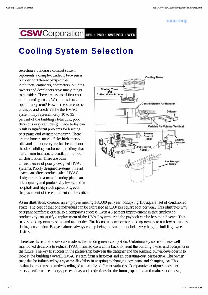
Selecting a building's comfort systemrepresents a complex tradeoff between anumber of different perspectives.Architects, engineers, contractors, buildingowners and developers have many thingsto consider. There are issues of first costand operating costs. What does it take tooperate a system? How is the space to bearranged and used? While the HVACsystem may represent only 10 to 15percent of the building's total cost, poordecisions in system design made today canresult in significant problems for buildingoccupants and owners tomorrow. Thereare the horror stories of sky high energybills and almost everyone has heard aboutthe sick building syndrome – buildings thatsuffer from inadequate ventilation or poorair distribution. There are otherconsequences of poorly designed HVACsystems. Poorly designed systems in retailspace can affect product sales. HVACdesign errors in a manufacturing plant canaffect quality and productivity levels, and inhospitals and high tech operations, eventhe placement of the equipment can be critical.
As an illustration, consider an employee making $30,000 per year, occupying 150 square feet of conditionedspace. The cost of that one individual can be expressed as $200 per square foot per year. This illustrates whyoccupant comfort is critical to a company's success. Even a 5 percent improvement in that employee'sproductivity can justify a replacement of the HVAC system. And the payback can be less than 2 years. Thatmakes building owners sit up and take notice. But it's not uncommon for building owners to run low on moneyduring construction. Budgets almost always end up being too small to include everything the building ownerdesires.
Therefore it's natural to see cuts made as the building nears completion. Unfortunately some of these wellintentioned decisions to reduce HVAC installed costs come back to haunt the building owner and occupants inthe future. The key to success in the partnership between the designer and the building owner/developer is tolook at the building's overall HVAC system from a first-cost and an operating-cost perspective. The ownermay also be influenced by a system's flexibility in adapting to changing occupants and changing use. Thisevaluation requires the understanding of at least five different variables. Comparative equipment cost andenergy performance, energy prices today and projections for the future, operation and maintenance costs,
1 of 2 7/14/2000 8:53 AM
Cooling System Selection http://www.csw.com/apogee/coolhtml/cxss.htm

Advice Home | Index | FAQs | Contact Us
1 of 1 7/14/2000 12:12 PM
Cooling System Alternatives http://www.csw.com/apogee/coolhtml/home.htm

operating characteristics of the system and past experience with HVAC systems.
The situation is even more complicated today with the phase out of certain refrigerants, tighter regulations, andheightened concerns over air emission and global warming gasses. There are a wide range of design options,trade-offs and considerations.
Top of Cooling | Index | FAQs | Contact Us
2 of 2 7/14/2000 8:53 AM
Cooling System Selection http://www.csw.com/apogee/coolhtml/cxss.htm
Fundamentals
Top of Cooling | Index | FAQs | Contact Us
1 of 1 7/13/2000 10:02 PM
Fundamentals http://www.csw.com/apogee/coolhtml/cxf.htm

Related Efficiency Upgrades
Economizer Cycles
Related Efficiency Upgrades - Heat Recovery
Related Efficiency Upgrades - Chiller Sequencing
Related Efficiency Upgrades - Lighting
Related Efficiency Upgrades - HVAC Design
Related Efficiency Upgrades - Energy Management
Top of Cooling | Index | FAQs | Contact Us
1 of 1 7/13/2000 10:05 PM
Related Efficiency Upgrades http://www.csw.com/apogee/coolhtml/cxfr.htm

Economizer Cycles
A number of options exist for heat recovery in conditioned spaces. The selection depends on site conditionsand economics. The main categories are:
Air-to-air heat recovery Direct evaporative cooling Combination (3-stage) cycles Outdoor air or ventilation cycle Indirect evaporative cooling Chiller "free" cooling
Air-to-air Heat Recovery - is often referred to as the exhaust air heat recovery cycle, since heat is recoveredfrom the warm air exhausted from a building or process. Categories include:
Process-to-process, Process-to-comfort, Comfort-to-comfort.
Within these categories there are different options. Making the selection is often dependent on the proximity ofthe exhaust to the supply air ducts. Consider these factors when making an evaluation:
Energy costs The amount of useable waste The temperature of waste heat Other conservation options The effects on the HVAC system The effect on relative humidity The proximity of the supply and demand
Where exhaust and supply air ducts are not in close proximity, consider the glycol "run-around" loop system.
Top of Cooling | Index | FAQs | Contact Us
1 of 1 7/13/2000 10:05 PM
Economizer Cycles http://www.csw.com/apogee/coolhtml/cfre.htm
Related Efficiency Upgrades - HeatRecovery
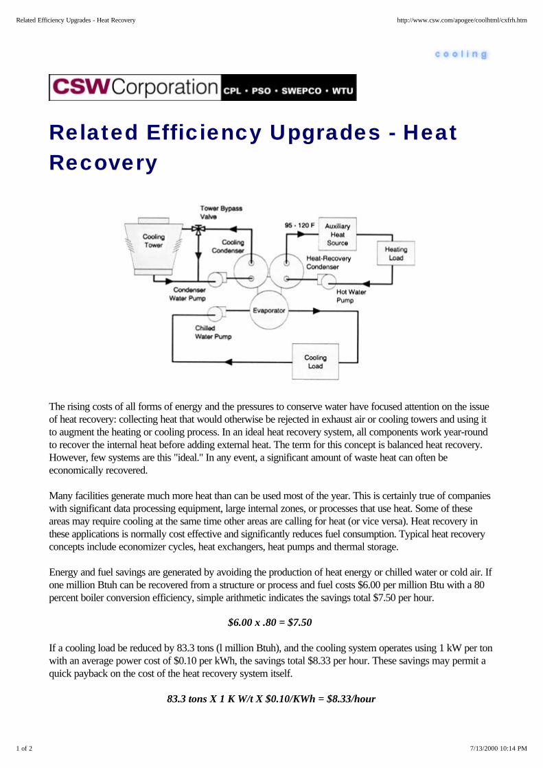
The rising costs of all forms of energy and the pressures to conserve water have focused attention on the issueof heat recovery: collecting heat that would otherwise be rejected in exhaust air or cooling towers and using itto augment the heating or cooling process. In an ideal heat recovery system, all components work year-roundto recover the internal heat before adding external heat. The term for this concept is balanced heat recovery.However, few systems are this "ideal." In any event, a significant amount of waste heat can often beeconomically recovered.
Many facilities generate much more heat than can be used most of the year. This is certainly true of companieswith significant data processing equipment, large internal zones, or processes that use heat. Some of theseareas may require cooling at the same time other areas are calling for heat (or vice versa). Heat recovery inthese applications is normally cost effective and significantly reduces fuel consumption. Typical heat recoveryconcepts include economizer cycles, heat exchangers, heat pumps and thermal storage.
Energy and fuel savings are generated by avoiding the production of heat energy or chilled water or cold air. Ifone million Btuh can be recovered from a structure or process and fuel costs $6.00 per million Btu with a 80percent boiler conversion efficiency, simple arithmetic indicates the savings total $7.50 per hour.
$6.00 x .80 = $7.50
If a cooling load be reduced by 83.3 tons (l million Btuh), and the cooling system operates using 1 kW per tonwith an average power cost of $0.10 per kWh, the savings total $8.33 per hour. These savings may permit aquick payback on the cost of the heat recovery system itself.
83.3 tons X 1 K W/t X $0.10/KWh = $8.33/hour
1 of 2 7/13/2000 10:14 PM
Related Efficiency Upgrades - Heat Recovery http://www.csw.com/apogee/coolhtml/cxfrh.htm

The use of water in cooling systems can also be reduced with heat recovery. Water-cooled electric waterchillers typically use 4 gallons of water per ton-hour in the cooling tower. If a cooling load can be reduced by83.3 tons (l million Btuh), 333 gallons of water per hour can be conserved. Heat recovery in absorptionchillers can conserve even more.
Site and source air emissions can also be reduced through heat recovery. The principal contributor to globalwarning is CO2 which is produced by burning fossil fuels. Other emissions will be proportionately reduced,including sulfur and nitrous oxides, carbon monoxide and particulates.
Other benefits may also occur. For example, if process or internal heat can be recovered and used, it couldreduce the need for, or even eliminate, a cooling tower or other device used to reject previously unwanted orunused waste heat.
And Furthermore . . .
Double Bundle Condenser Auxiliary Condenser
Top of Cooling | Index | FAQs | Contact Us
2 of 2 7/13/2000 10:14 PM
Related Efficiency Upgrades - Heat Recovery http://www.csw.com/apogee/coolhtml/cxfrh.htm

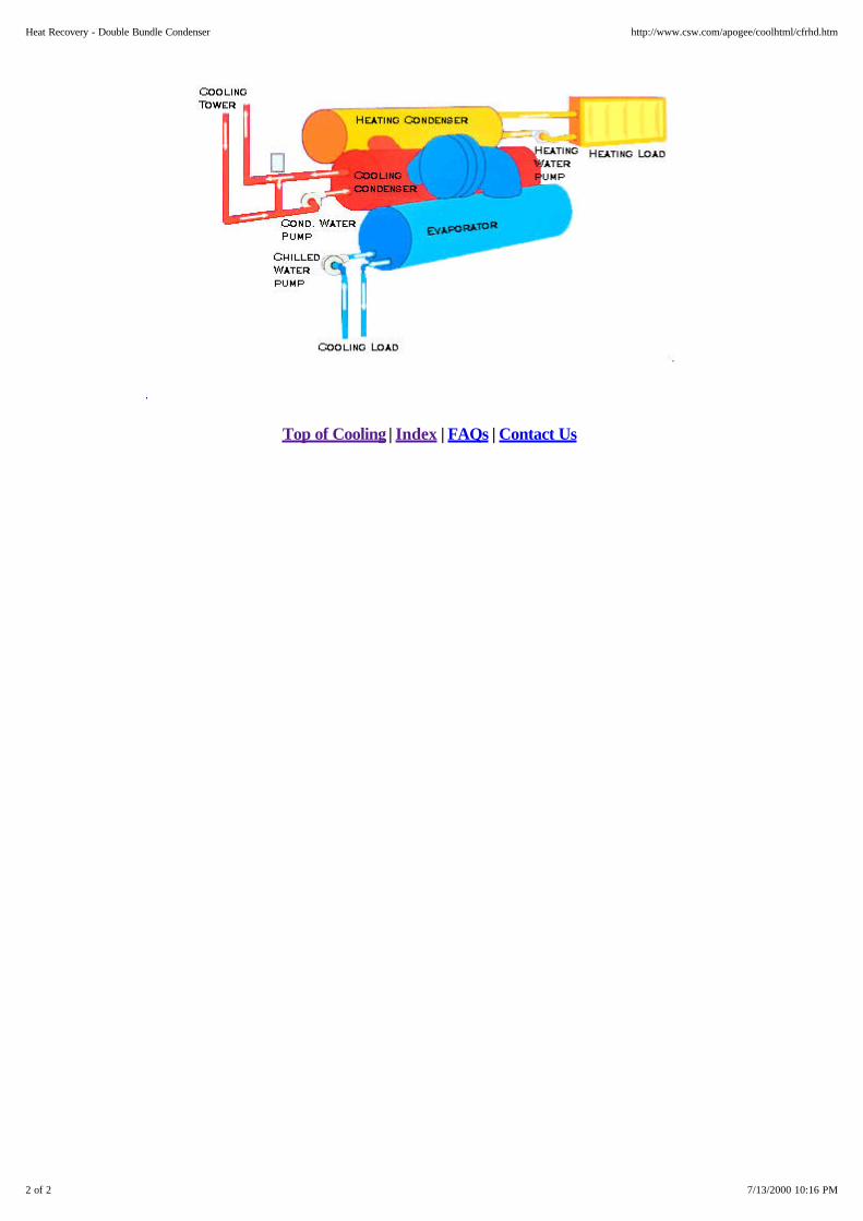
Heat Recovery - Double BundleCondenser
Double-bundle condenser or 2-condenser heat recovery can significantly reduce space, domestic water,and/or process water heating costs. Waste heat, normally rejected to the cooling tower, is captured andreused. The example shown here heats water to between 95°F and 120°F to satisfy concurrent cooling andheating loads. The term "double bundle" or split-head condenser refers to one enclosed shell housing two tubebundles separated on the water side.
When the heating load is present, heat is recovered by reducing the amount of heat rejected to the coolingtower. This is done by modulating water flow through (and around) the cooling tower.
As the water temperature returning from the heating load falls, the tower bypass valve diverts and increasingamount of water directly back to the condenser, transferring heat to the heat recovery condenser bundle andmaximizing energy recovery. Hot water up to about 130°F can be produced in certain designs. However, theeconomics of doing this depends on the relative value of power used and heating energy saved. In addition, thisevaluation requires a careful consideration of electric and fuel rate structures.
A back-up heat source is required if the chiller waste heat is not sufficient to reliably satisfy the entire heatingload. And, the double-bundle condenser heat recovery option must be specified when the chiller is ordered.Obviously, the chiller operates at a higher kW per ton when heating water above ~ 95°F, but this is normallyvery cost-effective since the COP of heating is high.
1 of 2 7/13/2000 10:16 PM
Heat Recovery - Double Bundle Condenser http://www.csw.com/apogee/coolhtml/cfrhd.htm
Top of Cooling | Index | FAQs | Contact Us
2 of 2 7/13/2000 10:16 PM
Heat Recovery - Double Bundle Condenser http://www.csw.com/apogee/coolhtml/cfrhd.htm
Heat Recovery - Auxiliary Condenser
An auxiliary condenser can be added to a chiller to capture "waste" heat rejected from the chiller's condenser.The auxiliary condenser scheme is similar to the double-bundle or 2-condenser system except the auxiliarycondenser is typically smaller than the main cooling (tower) condenser. This recaptured energy is often used toheat water for domestic or process use. An auxiliary condenser is simply another smaller condenser bundleadded to the chiller. A portion of the hot condenser gas migrates to this device heat the water flowing throughit. Unlike the "double-bundle" method of heat recovery, however, there is no modulating control to regulate theamount of heat rejected. Consequently, the auxiliary condenser simply captures heat at whatever temperaturelevel the cooling condenser is operating.
The best auxiliary condenser applications show extremely fast paybacks. These include preheating water foruse in hospital laundries, domestic hot water for hotels, and boiler feed water for process applications.
Relatively low temperature water is produced by the auxiliary condenser. However, unlike a double bundlecondenser, the kW per ton actually goes down when the heating water is being produced. While a chiller canbe field-retrofitted with an auxiliary condenser, it costs less if it is included when the chiller is first ordered.
Top of Cooling | Index | FAQs | Contact Us
1 of 1 7/13/2000 10:16 PM
Heat Recovery - Auxiliary Condenser http://www.csw.com/apogee/coolhtml/cfrha.htm

Related Efficiency Upgrades - ChillerSequencing Arranging chiller evaporators in series canreduce system flow rate and pumpingpower by increasing the system's chilledwater range (i.e., the difference betweensupply and return chilled watertemperature). This technique can also beused to reduce condenser waterflow. Sincethe direction of waterflow through thecondenser counters that of the evaporator,the series arrangement assures that thechiller producing the coldest chilled waterreceives the coldest tower water.Consequently, the system's overalloperating efficiency is enhanced. However,the adverse effect of elevated condenser water temperature on chiller performance forces the designer to pipethe condensers in parallel even if the evaporators are piped in series.
Sequencing the chillers also reduces system energy consumption while enhancing reliability. System loads canvary over a wide range. It is conceivable that a multiple chiller system can satisfy the building cooling loadswith the operation of only one chiller. During these periods, the energy required to operate the second chillercan be conserved. And, in the event that one chiller fails or requires maintenance, the other machine is stillavailable to provide cooling.
System temperature control can be accomplished in several ways. One control strategy assigns the systemdesign set point value as each chiller's chilled water set point. When the system load is 50 percent of totalcapacity, either chiller can satisfy the cooling requirement (this assumes both machines were have the samecapacity and sized to produce design leaving water temperature). Which chiller operates depends upon whichmachine is sequenced on first. For system loads greater than 50 percent, the upstream chiller is preferentiallyloaded because it will attempt to produce the design chilled water temperature.
Another control scheme staggers the chiller setpoints. The downstream chiller is loaded first, and anyadditional load is passed to the upstream machine. Equal loading is accomplished by placing the temperaturesensors for both machines after the downstream unit. This loads both chillers proportionately to their maximumcapacity. Because the flow rate through each chiller is actually the entire system flow, some of the pumpingsavings provided by reduced flow are offset by higher system, pressure drops.
Flow and pressure drop limitations make it difficult to apply more than two chillers in series.
And Furthermore . . .
1 of 2 7/13/2000 10:18 PM
Related Efficiency Upgrades - Chiller Sequencing http://www.csw.com/apogee/coolhtml/cxfrc.htm

Parallel Chiller Sequencing Parallel chiller sequencing can reduce energyconsumption while enhancing reliability. Buildingcooling loads can vary widely. It is conceivable thata multiple-chiller system can satisfy the buildingcooling load by operating only one chiller.However, since both pumps are normally runcontinuously to avoid starving system cooling coils,the operating chiller must produce cold enoughwater to offset the bypass water flowing throughthe inactive chiller. Chiller sequencing also provides additional reliability for the system. If one of the chiller failsor requires maintenance, the other machine is still available to provide cooling.
Parallel-sequenced chillers are typically piped in either of two pumping arrangements: One arrangement uses asingle chilled water circulating pump. The other uses separate, dedicated chiller pumps (as shown in theillustration).
To optimize the efficiency of the sequenced chillers, control strategies such as "1/3 - 2/3 flip-flop" can be used.In this example, the smaller chiller - which is sized to satisfy one third of the building cooling load - is startedfirst. When the load exceeds the capacity of the smaller machine, it is shut off and the larger chiller is started.Finally, when the cooling load exceeds the capacity of that machine, the smaller chiller is restarted so that bothchillers are running. This control strategy optimizes the match between building load and chiller capacity,enhancing the overall efficiency of the system.
Using a single chilled water circulating pump does not provide standby capability. If separate, dedicated chilledwater pumps are allowed to be sequenced, system waterflow will decrease significantly as the chiller/pumppairs are sequenced off. The reduction in system flow may starve some areas of the building where coolingloads still exist.
Top of Cooling | Index | FAQs | Contact Us
1 of 1 7/13/2000 10:22 PM
Parallel Chiller Sequencing http://www.csw.com/apogee/coolhtml/cfrcp.htm
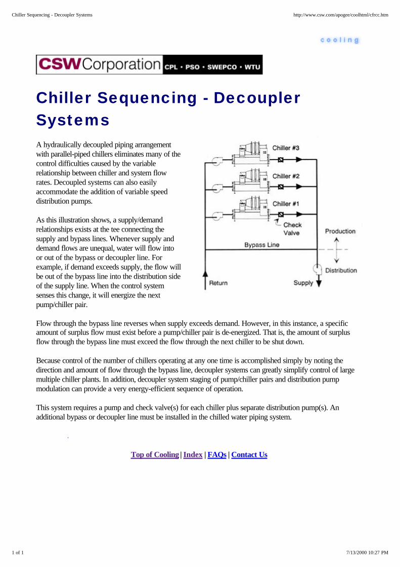
Chiller Sequencing - DecouplerSystems A hydraulically decoupled piping arrangementwith parallel-piped chillers eliminates many of thecontrol difficulties caused by the variablerelationship between chiller and system flowrates. Decoupled systems can also easilyaccommodate the addition of variable speeddistribution pumps.
As this illustration shows, a supply/demandrelationships exists at the tee connecting thesupply and bypass lines. Whenever supply anddemand flows are unequal, water will flow intoor out of the bypass or decoupler line. Forexample, if demand exceeds supply, the flow willbe out of the bypass line into the distribution sideof the supply line. When the control systemsenses this change, it will energize the nextpump/chiller pair.
Flow through the bypass line reverses when supply exceeds demand. However, in this instance, a specificamount of surplus flow must exist before a pump/chiller pair is de-energized. That is, the amount of surplusflow through the bypass line must exceed the flow through the next chiller to be shut down.
Because control of the number of chillers operating at any one time is accomplished simply by noting thedirection and amount of flow through the bypass line, decoupler systems can greatly simplify control of largemultiple chiller plants. In addition, decoupler system staging of pump/chiller pairs and distribution pumpmodulation can provide a very energy-efficient sequence of operation.
This system requires a pump and check valve(s) for each chiller plus separate distribution pump(s). Anadditional bypass or decoupler line must be installed in the chilled water piping system.
Top of Cooling | Index | FAQs | Contact Us
1 of 1 7/13/2000 10:27 PM
Chiller Sequencing - Decoupler Systems http://www.csw.com/apogee/coolhtml/cfrcc.htm

Related Efficiency Upgrades -Lighting
One of the first things to consider when evaluating a cooling system is lighting. The fact is a large portion of theenergy consumed by the lighting system shows up as heat in the conditioned space. Therefore, improvementsin lighting efficiency (technically called efficacy) decrease building cooling loads. However, this will alsoincrease the heating load during the heating season. While uncommon, this increase can be a concern if theoriginal building design was "counting on" the heat given off by lights to reduce the size of (or even eliminate) aheating plant. Estimates of .the final impact of a lighting retrofit or change should be made by qualifiedprofessionals taking into account the specifics of a building.
In general, if the original building design was conservative, the heating system will usually be able to handle theadded load. And, in most air conditioned commercial and industrial buildings annual total operating costs arelowered through improvements in lighting efficacy (since heating operating costs are usually smaller thancooling). Once again, the final economic evaluation should be made by qualified professionals familiar with thebuilding in question as well as the prevailing power and fuel use and costs for the building.
As a general rule of thumb, any air-conditioned commercial or industrial building with a high percentage ofincandescent lighting will find that conversion to a more efficient and effective lighting source will have asignificant impact on building cooling and heating loads. Only 10 percent of the energy going into anincandescent light is converted to light, the rest of the energy is given off as heat. For a fluorescent light, twiceas much of the energy is converted to light, but this is still only 20 percent of the total energy.
This makes it easy to understand why improving the efficiency of the lighting can result in a 20 percent savingsin cooling costs in an office building.
The formula used to calculate the heating load for incandescent lighting looks like this:
Lighting Watts x 0.9 x 3.412 Btuh / Watt = Heat Load on cooling system in tons 12,000 Btu/Ton
For fluorescent lighting the only element that changes is the lighting conversion efficiency:
Lighting Watts x 0.8 x 3.412 Btuh / Watt = Heat Load on cooling system in tons 12,000 Btu/Ton
As an example, forty 100-watt incandescent lamps require 12,283 Btu of cooling (slightly over one ton). Thesite could use 27 four-lamp fluorescent fixtures (or 4400 watts) at the same one ton of cooling load, yetproduce 10 percent more light.
Are lighting efficiency improvements important for other reasons? They may be! While certainly not an answerto the CFC phaseout question, proper lighting selection may offer a lower cost alternative to adding orreplacing chillers. And, there are numerous situations where an upgrade in lighting can improve occupant
1 of 2 7/13/2000 10:28 PM
Related Efficiency Upgrades - Lighting http://www.csw.com/apogee/coolhtml/cfrl.htm

comfort and productivity. Coupled with the energy savings, this all adds up to improved profitability.
Top of Cooling | Index | FAQs | Contact Us
2 of 2 7/13/2000 10:28 PM
Related Efficiency Upgrades - Lighting http://www.csw.com/apogee/coolhtml/cfrl.htm
Related Efficiency Upgrades - HVACDesign
Even though the HVAC system design is often well thought out by the original building designer for an intendedbuilding occupant and use characteristic, something less than design excellence is often installed. This frustratesbuilding operators and promotes supplying the coldest chilled water or air necessary to satisfy the area furthestoff the design point. Therefore, it is extremely important that building designs consider this fact of life and offeras much occupant control as possible. This will, at least partially eliminate the problem of having to supply agiven temperature just because one area in a zone cannot otherwise be adequately cooled.
Probably one of the best ways to minimize a building's energy use is to correct the air balance after theoccupants are settled in. In practice, very few buildings are re-balanced after the HVAC system is installed.This leaves operator no choice but to tinker with air handler dampers and diverters. This is far inferior andtypically results in a higher operating cost.
Top of Cooling | Index | FAQs | Contact Us
1 of 1 7/13/2000 10:28 PM
Related Efficiency Upgrades - HVAC Design http://www.csw.com/apogee/coolhtml/cfrv.htm

Related Efficiency Upgrades - EnergyManagement
While the slick graphics and apparent sophistication of today's energy management systems can lure buildingmanagers into some pretty expensive hardware and software, their effectiveness, and cost effectiveness, restson the efficiency of cooling system itself. Therefore, the first step in any chiller energy management programshould be to performance monitor the existing cooling equipment and re-evaluate building cooling loads.Cooling tower operational performance should be monitored (including total power use of the chiller plus thecooling tower). The goal should be to gather enough information to help operators determine the optimal chilleroperational configuration. Whenever possible, include a manual method (typically via the computer console) ofsetting supply chilled water and/or air temperatures. If this isn't done, nine times out of ten an operator will runmore chillers than necessary.
The primary purpose of any energy management system is to provide a predictive measure of how the overallsystem should be operated to maximize comfort while minimizing costs. Operators should be trained andrewarded for their understanding of these issues and conscientiousness in getting the most out of theequipment. Otherwise, they will make the easiest choices in responding to occupant hot calls and cold calls,essentially wasting energy instead of solving air handler problems and operating chillers correctly.
After the reliability of the energy management system is established, building owners or managers shouldconsider automating the chilled water reset and the cooling tower controls.
Top of Cooling | Index | FAQs | Contact Us
1 of 1 7/13/2000 10:29 PM
Related Efficiency Upgrades - Energy Management http://www.csw.com/apogee/coolhtml/cfrm.htm

Energy Prices
Electric Rate Schedules
Fuel Rate Schedules
Top of Cooling | Index | FAQs | Contact Us
1 of 1 7/13/2000 10:29 PM
Energy Prices http://www.csw.com/apogee/coolhtml/cxfe.htm

Electric Rate Schedules
Electric power use is metered in two ways: on maximum kilowatt use during a given time period (i.e., kWdemand) and on total cumulative use in kilowatt hours (kWh). A customer's electric rate is set using a complexprocess of tracking cost of services and seeking regulatory approval. The general theory is that demandcharges reflect the utilities' fixed costs of providing a given level of power, and energy charges reflect thevariable portion of those costs. HVAC designers must have a good understanding of the electric rate design inthe area in which the building will operate before they can make prudent decisions.
Power companies often use a meter that records the power use during either a 15 or 30 minute time window.The average power used during that window is used to calculate the kW demand. The peak demand used forbilling purposes in any month can be:
1. Dependent on the time of day (i.e., on-peak and off-peak time periods) and/or the day of the week (e.g.,Monday through Friday): The metering system tracks the highest usage anytime during the month under theappropriate time windows. These pricing schedules are generally referred to as Time of Use (TOU) rates.
2. The demand rate can be Seasonally Differentiated: For example, the demand charge might be higher duringthe summer than during the winter, or visa versa.
3. The demand rate can be arranged in Declining Blocks: This is where the demand charge up to a given levelis at one price with the price declining above that level. For example, the demand charge might be $10 per kWup to 10,000 kW demand, and drop to $6 per kW for demands in excess of 10,000 kW.
4. The demand rate can be set in Interruptible Blocks: The demand charge depends upon whether thecustomer can reduce electrical demand to a given level if it is notified in advance by the utility. The pricereduction often varies with the time of notice (i.e., the discount is higher if shorter notice is given). Some utilitiesalso offer direct load control for air conditioning and water heating equipment, the utility itself can cycle thisequipment on and off for brief periods.
5. Demand charge Ratchet: Certain rate designs incorporate minimum billing demands based upon historicalpeak demands. For example, if the peak demand last summer was 500 kW and the rate design has a 50%ratchet, the minimum billing demand would be 250kW for the following months, regardless of whether theactual demands were lower.
The meter recording kWh power use during either a 15 or 30 minute time window also tallies total kWh use.This meter is read at roughly monthly intervals and total power use is billed according to applicable pricingschedules. The type of energy charge pricing in common use includes:
1. Time of day (i.e., on-peak and off-peak time periods) and/or the day of the week (e.g., Monday throughFriday): These pricing schedules are generally referred to as Time of Use (TOU) rates.
2. Seasonally Differentiated: For example, the energy charge might be higher during the summer than during thewinter, or visa versa.
1 of 2 7/13/2000 10:30 PM
Electric Rate Schedules http://www.csw.com/apogee/coolhtml/cfee.htm

3. Declining Blocks: This is typically where the energy charge to a given level is at one price and that pricedeclines above that level. For example the energy charge might be $0.05 per kWh for the first 100,000 kWhrsused in a month and drop to $0.04 per kWh for the next 1000,000 kWhrs.
Electric rate schedules can be confusing and, therefore, subject to misinterpretation. Always check with yourlocal utility company representative for assistance in this area.
Top of Cooling | Index | FAQs | Contact Us
2 of 2 7/13/2000 10:30 PM
Electric Rate Schedules http://www.csw.com/apogee/coolhtml/cfee.htm

Fuel Rate Schedules
Liquid and gaseous fuels are generally sold on a volume basis (e.g., $/cubic foot, or $/gal) or, with natural gas,on a heat content basis (e.g. $/therm). Solid fuels are usually on a dollar per weight basis. Liquid and gaseousfuels usually have some level of seasonal price variation with prices higher during the peak heating season. Thefinal price at the "burner tip" for liquid and gaseous fuels is composed of at least three major components:wellhead, transportation, and the local distribution company (LDC).
In addition, some natural gas distribution companies have fuel use demand meters where peak hourly gas useestablishes a monthly demand charge similar to electric rate schedules. The most common rate designs aredeclining blocks and seasonally differentiated pricing as discussed before. Since most fuel suppliers areconcerned about being able to meet the peak winter requirements, they are often willing to reduce price forthose who they can interrupt. The most common situation is where natural gas suppliers offer a discount tothose who can switch to fuel oil during this peak period. There are also situations where the price for naturalgas all year long depends upon this alternative fuel. For example, natural gas suppliers might have threedifferent interruptible gas tariffs, depending upon whether the site uses No.2, No.4, or No.6 oil.
Large customers can now generally purchase natural gas at the wellhead (or even purchase the wellhead),contract for transportation, or merely arrange final delivery from the LDC. This can provide the large customerlower pricing, but does require significant management time.
Top of Cooling | Index | FAQs | Contact Us
1 of 1 7/13/2000 10:30 PM
Fuel Rate Schedules http://www.csw.com/apogee/coolhtml/cfef.htm

Vapor Compression Systems
Vapor compression refrigeration is the primary method used to provide mechanical cooling. All vaporcompression systems consist of four basic components (plus the interconnecting piping): evaporator,compressor, condenser, and an expansion device. The evaporator and condenser are heat exchangers thatevaporate and condense the refrigerant while absorbing and rejecting heat. The compressor takes therefrigerant vapors from the evaporator and raises the pressure sufficiently for the vapor to condense in thecondenser. The expansion device controls the flow of condensed refrigerant at this higher pressure back intothe evaporator.
Historically, the common refrigerants were R-11, R-12,R-22, and compounds in the R-500 series. With the CFCphaseout, new refrigerants have been developed toreplace R-11 and R-12 in new equipment. These newrefrigerants can also be used to retrofit existing equipmentin many cases. However, these retrofits are not "drop-ins"and should be done by trained technicians.
Food processors often use ammonia (R-717). Whilepotentially hazardous, ammonia is inexpensive andenvironmentally benign. Experts anticipate wider use of ammonia due to concerns over CFC phase-out.Interestingly, R-22 was developed as a safe alternative for cooling systems that would perform best atammonia refrigerant characteristics.
The manufacturer selects the specific refrigerant used in any equipment to best match the cooling system designand size. The availability and cost of these refrigerants and the consequences of refrigerant leaks and disposalhave become very serious concerns for today's building owners and the design community. Each of theseissues is addressed in other areas of this interactive knowledge program.
Select from these areas of interest . . .
The Evaporator Evaporator Control
The Condenser
Top of Cooling | Index | FAQs | Contact Us
1 of 1 7/13/2000 10:31 PM
Vapor Compression Systems http://www.csw.com/apogee/coolhtml/cxfv.htm
Vapor Compression Systems - TheEvaporator
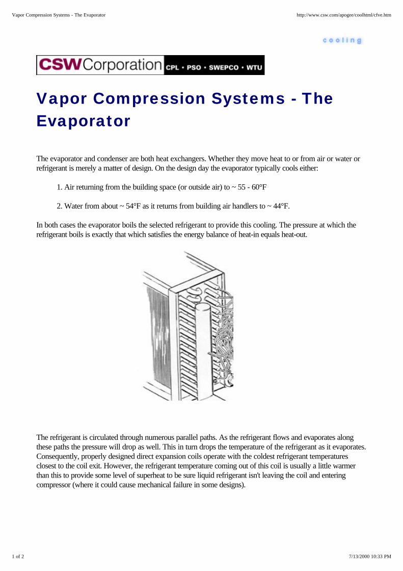
The evaporator and condenser are both heat exchangers. Whether they move heat to or from air or water orrefrigerant is merely a matter of design. On the design day the evaporator typically cools either:
1. Air returning from the building space (or outside air) to ~ 55 - 60°F
2. Water from about ~ 54°F as it returns from building air handlers to ~ 44°F.
In both cases the evaporator boils the selected refrigerant to provide this cooling. The pressure at which therefrigerant boils is exactly that which satisfies the energy balance of heat-in equals heat-out.
The refrigerant is circulated through numerous parallel paths. As the refrigerant flows and evaporates alongthese paths the pressure will drop as well. This in turn drops the temperature of the refrigerant as it evaporates.Consequently, properly designed direct expansion coils operate with the coldest refrigerant temperaturesclosest to the coil exit. However, the refrigerant temperature coming out of this coil is usually a little warmerthan this to provide some level of superheat to be sure liquid refrigerant isn't leaving the coil and enteringcompressor (where it could cause mechanical failure in some designs).
1 of 2 7/13/2000 10:33 PM
Vapor Compression Systems - The Evaporator http://www.csw.com/apogee/coolhtml/cfve.htm

Shell and tube heat exchangers commonly have water circulated through the tubes and refrigerant boilingaround the tubes. There are also designs where refrigerant flows within the tubes and water flows over thetubes. Baffles are normally used in this case to direct water flow in a serpentine fashion to optimize heattransfer. Almost all large chillers use shell and tube evaporators with water flowing through the tubes.
Top of Cooling | Index | FAQs | Contact Us
2 of 2 7/13/2000 10:33 PM
Vapor Compression Systems - The Evaporator http://www.csw.com/apogee/coolhtml/cfve.htm

Vapor Compression Systems -Evaporator Control
In comfort cooling applications, actual cooling loads are seldom at full loadconditions. Capacity control is achieved in finned coil evaporators thatdirectly chill air by splitting the coil into independent sections. The principalreason is to permit coil sections to be activated and deactivated to bettermatch coil cooling capacity with compressor loading. The combination ofsmaller coil sections controlled by correspondingly sized expansion valvesimproves valve performance and part load humidity control.
Capacity control in shell and tube evaporators is usually handled using thereturn water temperature. For example, if the full-load temperature range forchilled water is from 44°F to 54°F, water returning at 50°F indicates thecooling load is about 60%. Liquid refrigerant is metered to the evaporator tomatch the load using an orifice plate system or an expansion valve. On largechillers, the expansion valve is pilot operated.
1 of 2 7/13/2000 10:34 PM
Vapor Compression Systems - Evaporator Control http://www.csw.com/apogee/coolhtml/cfvp.htm

Top of Cooling | Index | FAQs | Contact Us
2 of 2 7/13/2000 10:34 PM
Vapor Compression Systems - Evaporator Control http://www.csw.com/apogee/coolhtml/cfvp.htm

Vapor Compression Systems - The Condenser
The refrigerant is recovered by condensing it in a heat exchanger using air or water to reject the heat. Aircooled condensers are most common in smaller sizes, up to about 200 ton capacity. Technically, there is noupper limit on the size of an air cooled condenser, but operating cost issues usually dictate water cooled unitsfor applications over about 100 tons.
There are two water cooled designs: cooling towers and evaporative condensers. Both work on the principalof cooling by evaporating water into a moving air stream. The effectiveness of this evaporative cooling processdepends upon the wet bulb temperature of the air entering the unit, the volume of air flow and the efficiency ofthe air/water interface.
1 of 3 7/13/2000 10:36 PM
Vapor Compression Systems - The Condenser http://www.csw.com/apogee/coolhtml/cfvc.htm

Evaporative condensers use water sprays and air flow to condense refrigerant vapors inside the tubes. Thecondensed refrigerant drains into a tank called a liquid receiver. Refrigerant subcooling can be accomplishedby piping the liquid from the receiver back through the water sump where additional cooling reduces the liquidtemperature even further.
Cooling towers are essentially large evaporative coolers where the cooled water is circulated to a remote shelland tube refrigerant condenser. Notice the cooling water is circulating through the tubes while refrigerant vaporcondenses and gathers in the lower region of the heat exchanger. Notice also that this area "subcools" therefrigerant below the temperature of condensation by bringing the coldest cooling tower water into this area ofthe condenser. The warmed cooling water is sprayed over a fill material in the tower. Some of it evaporates inthe moving air stream. The evaporative process cools the remaining water.
2 of 3 7/13/2000 10:36 PM
Vapor Compression Systems - The Condenser http://www.csw.com/apogee/coolhtml/cfvc.htm

The volume of water used by both evaporative condensers and cooling towers is significant. Not only doeswater evaporate just to reject the heat, but water must be added to avoid the buildup of dissolved solids in thebasins of the evaporative condensers or cooling towers. If these solids build up to the point that they foul thecondenser surfaces, the performance of the unit can be greatly reduced.
Top of Cooling | Index | FAQs | Contact Us
3 of 3 7/13/2000 10:36 PM
Vapor Compression Systems - The Condenser http://www.csw.com/apogee/coolhtml/cfvc.htm

Fundamentals - Once-Through Cooling
While once through cooling was once very common, only the smallest of cooling systems now use it. In thesedesigns, groundwater or city water is brought into the condenser (say at 60°F), heated to about 95°F and thenusually disposed of. But, look at how much water is being used! One ton of cooling would use over 41gallonsof water an hour! This is why most areas of the country banned once-through cooling years ago for anythingother than the smallest applications. However, there are certain situations where it could be a excellent way topreheat boiler feedwater or process water.
Top of Cooling | Index | FAQs | Contact Us
1 of 1 7/13/2000 10:04 PM
Fundamentals - Once-Through Cooling http://www.csw.com/apogee/coolhtml/cfo.htm

Chilled Water Temperature & Flow
Most large buildings use air handlers with chilled water coils. Historically, chilled water has been, supplied tothese air handlers at ~ 44°F on the warmest days of the summer and would return to the chiller at about ~ 54(i.e., 10°F warmer). Every ton of cooling delivered this way requires 2.4 gpm of water flow. Designprofessionals today have a multitude of alternatives available to them, including:
1. Increasing the difference between supply and return chilled water temperatures (called the chilled waterrange) to reduce chilled water pipe sizes and pumping power.
2. Increasing the coil surface area to permit higher chilled water supply temperatures,
3. And using lower temperature chilled water, perhaps in the 36 - 38°F range, to produce much colder supplyair, thereby reducing air handler air flows, fan power, and duct sizing (which can even reduce building height).
These factors can impact energy use in complex ways. For example, distributing low temperature chilled wateris often combined with increasing the chilled water range (e.g., supplying 38°F water and returning 58°Fwater). The chilled water flow is now only 1.2 gpm per ton, providing significant savings in chilled waterdistribution piping and pumps. However, producing 38°F water potentially requires more power and moreexpensive chiller designs. But, then again, maybe not. Certain building designs (such as churches, theaters, andoperating room suites) can be "naturals" for ice storage. Similarly, chilled water at 40 - 42°F can sometimesachieve similar benefits.
All of these tradeoffs are complex and obviously fall within the domain of the design professional. Each designrequires careful analysis, consideration of current and future building use, operating personnel qualifications,and the issues of initial investment and operating cost. This information is simply an explanation of some of theoptions available. Please refer to the specific cooling situation analyses elsewhere in this information system forfurther information.
Top of Cooling | Index | FAQs | Contact Us
1 of 1 7/13/2000 10:03 PM
Chilled Water Temperature & Flow http://www.csw.com/apogee/coolhtml/cfw.htm

Cooling Capacity
Cooling systems are defined by:
1. The temperatures they can "hold" either in the space and/or the process or equipment, and
2. The amount of heat they can remove at full capacity.
This heat removal is normally expressed in tons of cooling (or refrigeration) capacity. One ton of cooling equalsprecisely 12,000 Btu heat removal per hour (abbreviated Btuh) and comes from the way air handlers wereoriginally rated -- that is, how many pounds of ice would have to be loaded into them to provide the requiredspace cooling. When melting, ice gives up 144 Btu per pound. Therefore, one ton of cooling provides the sameamount of cooling energy as melting one ton of ice in 24 hours.
For any given piece of installed equipment, this rated capacity is dependent upon the method used by thesystem to reject heat. For example, a cooling system rejecting heat to a dry fan-coil condenser will normallyproduce fewer tons of cooling on the design day than that same chiller mechanical system rejecting heat to acooling tower. Put another way, any cooling system uses more power (or thermal input in the case ofabsorption chillers) to reject heat to a dry (air cooled) condensing system than to a wet (water cooled)condensing system.
This energy performance is defined by several measures: Coefficient of Performance (COP), kW/ton, EnergyEfficiency Ratio (EER), and similar terms for thermally activated systems.
Top of Cooling | Index | FAQs | Contact Us
1 of 1 7/13/2000 10:02 PM
Cooling Capacity http://www.csw.com/apogee/coolhtml/cfc.htm

ASHRAE and ARI Guidelines
ASHRAE Equipment Testing Standards
ASHRAE Ventilation Standards and Indoor Air Quality
ASHRAE Ventilation Guidelines
ARI
ARI Certification
Top of Cooling | Index | FAQs | Contact Us
1 of 1 7/13/2000 10:39 PM
ASHRAE and ARI Guidelines http://www.csw.com/apogee/coolhtml/cxfa.htm

ASHRAE Equipment TestingStandards
ASHRAE, the American Society of Heating, Refrigerating and Air-conditioning Engineers, is a world widetechnical and professional association, whose members are interested in the advancement of technology thatwill benefit the public. As part of its mission, ASHRAE establishes standards and procedures that advancesengineering science. ASHRAE standards address safety, ventilation and indoor air quality, energyconservation, testing-for-capacity-ratings. Of course these standards are updated periodically. The capacitytesting standards are used by equipment manufacturers to provide a comparable basis for publishing ratings.
The following ASHRAE Standards describe methods of testing-for-capacity-rating for various kinds ofequipment.
Standard No. Methods of Testing for Rating
20-1970 Remote Mechanical-Draft Air-cooled Refrigerant Condensers
22-1992* Water-cooled Refrigerant Condensers
23-1993* Positive Displacement Refrigerant Compressors and Condensing Units
24-1989* Liquid Coolers
30-1995 Liquid Chilling Packages
33-1978 Forced Circulation Air Cooling and Heating Coils
37-1988* Unitary Air-conditioning and Heat Pump Equipment
40-1986(RA92)* Heat Operated Unitary Air-conditioning Equipment for Cooling
64-1995* Remote Mechanical-Draft Evaporative Refrigerant Condensers
79-1984(RA91)* Room Fan-Coil Air Conditioners
*Approved by American National Standards Institute (ANSI) *RA - Reaffirmed standard followed by year of reaffirmation.
Top of Cooling | Index | FAQs | Contact Us
1 of 1 7/13/2000 10:40 PM
ASHRAE Equipment Testing Standards http://www.csw.com/apogee/coolhtml/cfae.htm

ASHRAE Ventilation Standards andIndoor Air Quality
The following ASHRAE Standards relate to ventilation and indoor air quality:
Std. No. Title
55-1992* Thermal Environmental Conditions for Human Occupancy
62-1989* Ventilation for Acceptable Indoor Air Quality
111-1988* Practices for Measuring, Testing, Adjusting and Balancing a Building's Heating, Ventilation,Air-conditioning and Refrigeration Systems
Guideline 3-1996 Reducing Emission of Fully Halogenated CFC Refrigerants in Refrigeration andAir-conditioning Equipment and systems
The following ASHRAE Standards address safety.
Std. No. Title
15-1994* Safety Code for Mechanical Refrigeration
34-1992* Numbers Designation and Safety Classification of Refrigerants
The following ASHRAE Standards relate to energy conservation in buildings.
Std. No. Title
90.1-1989 Energy Efficient Design of New Buildings (Except Low-Rise Residential Buildings)
100-1995 Energy Conservation in Existing Buildings
ASHRAE Standard 62-1989 and Standard 90.1-1989 are currently under review for revision.
*Approved by American National Standards Institute (ANSI)
Top of Cooling | Index | FAQs | Contact Us
1 of 1 7/13/2000 10:40 PM
ASHRAE Ventilation Standards and Indoor Air Quality http://www.csw.com/apogee/coolhtml/cfav.htm

ASHRAE Ventilation Guidelines
ASHRAE Standards specify that outside air for ventilation purposes should be introduced at the lowest volumenecessary to maintain adequate indoor air quality.
Ventilation is defined as the process of supplying or removing air by natural or mechanical means to or fromany space. This air may or may not have been heated or cooled. Ventilation is necessary to remove or diluteCO2, odors, and other contaminants from occupied or production process spaces.
Air contaminants are defined as gasses, such as CO, CO2, volatile organic compounds (VOCs), particulates,and other substances that affect indoor air quality (IAQ).
Dilution of indoor air is defined as a process that adds outdoor air (which is assumed to be less contaminated)to reduce the concentration of contaminants. This dilution can range from the use of "100% outdoor air" to acombination of outdoor and recirculated indoor air that has been filtered.
The ventilation rate is defined as the number of complete air changes for a given unit of time. Ventilation rate isalso referred to as the cubic feet per minute (cfm) of outdoor air that is required for meeting minimum IAQrequirements.
ASHRAE Standard 62-l989, Ventilation for Acceptable Indoor Air Quality, specifies the outdoor airventilation requirements at a minimum of 15 cfm per person in non-smoking areas, regardless of occupantusage, and a minimum of 60 cfm per person for smoking areas. Also the concentration of CO2 should notexceed 1,000 parts per million in conditioned spaces.
Appendix E of ASHRAE Standard 62-l989 contains a procedure for using cleaned recirculated air.Mechanical codes have also changed to allow increased recirculation rates based on the effectiveness of the airfiltering equipment.
ASHRAE Standard 62-1989 is currently under review for revision. The proposed revision contains significantcharges.
Top of Cooling | Index | FAQs | Contact Us
1 of 1 7/13/2000 10:41 PM
ASHRAE Ventilation Guidelines http://www.csw.com/apogee/coolhtml/cfag.htm
ARI
ARI, the Air-conditioning & Refrigeration Institute is an organization of equipment and componentmanufacturers. As a part of its mission, ARI establishes performance rating standards and sponsors andadministers certification programs for selected popular classes of HVAC equipment. Users and owners areencouraged to have their design engineers specify only certified equipment.
Top of Cooling | Index | FAQs | Contact Us
1 of 1 7/13/2000 10:41 PM
ARI http://www.csw.com/apogee/coolhtml/cfar.htm

ARI Certification
ARI Certification programs help ensure HVAC products perform as rated. In order for a piece of equipmentto be certified, its rating and performance must meet or exceed the applicable ARI Standard for Rating.Further, testing must occur within the specified range of standard rating conditions. The Unitary equipmentlisted represents more than 90 percent of the total U.S. output of equipment falling within the program scopeand rated below 135,000 Btuh cooling capacity.
To comply with the program, tolerances typically must fall within plus or minus 5 percent. For example, anyproduction unit, when tested, must have capacities, air-flows, energy efficiency ratios and coefficients ofperformance not less than 95 percent of its rated values.
Participating manufacturers must file certification data with ARI on all the models it manufactures within thescope of the programs. This information is evaluated by ARI before models are listed. Additional testing isrequired on any models with questionable data. In addition to evaluation of data ARI conducts standardperformance tests and, in some programs, random testing.
The manufacturer of a model which fails to pass specified tests faces two alternatives: re-rate the model inquestion to reflect its tested performance, or withdraw the model from the product line. Failing this, themanufacturer's right to use the ARI certification symbol on all models is withdrawn, and its name and listingsare deleted from the directory.
ARI publishes five Directories of Certified Products. Individuals or companies in or allied with the Heating,Refrigeration or Air-conditioning industries may obtain free directories simply by writing to ARI. Others mayobtain a directory for a modest fee, currently $6 per copy.
1. Directory of Certified Unitary Equipment includes:
Unitary air-conditioners Unitary air-source heat pumps Sound-rated outdoor unitary equipment
2. Directory of Certified Applied Air-Conditioning Products includes:
Air-cooling and air-heating coils Central station air-handling units Room fan-coil air-conditioners Ground water source heat pumps Packaged terminal air-conditioners Packaged terminal heat pumps Water-source heat pumps Variable air volume terminals Ground source closed-loop heat pumps Unitary large equipment
1 of 2 7/13/2000 10:41 PM
ARI Certification http://www.csw.com/apogee/coolhtml/cfac.htm

Centrifugal and rotary screw water chilling packages
3. Directory of Certified Drinking Water Coolers
4. Directory of Certified Automatic Commercial Ice-Cube Machines and Ice-storage Bins
5. Directory of Certified Transport Refrigeration Units
Top of Cooling | Index | FAQs | Contact Us
2 of 2 7/13/2000 10:41 PM
ARI Certification http://www.csw.com/apogee/coolhtml/cfac.htm

System Economics Most people make a purchase to solve a real or
perceived problem. They use economic evaluations to justify their decision. With chillers, problems can rangefrom inadequate capacity, chiller failure or high energy bills to the fear of CFC issues. In this section we willaddress the economics of chiller alternatives. A number of factors influence the costs of owning and operatinglarge water chillers. These include:
1. Installed first cost, including any building modifications to accommodate one particular alternative overothers.
2. Operating costs, including all the fuel, electric, and water costs (including the acquisition, treatment, anddisposal of sewered water) to accommodate one alternative over others.
3. Maintenance costs, including preventive maintenance and the monitoring of refrigerants to minimizelosses. Materials and supplies are also included here.
4. Insurance and Property Taxes.
5. Replacement Provisions, which takes into account the useful lives of the alternatives.
6. Financing, depreciation, and income taxes should also be considered. The money invested has a timevalue (interest) and there are usually tax consequences that affect decisions. It's usually a good idea toconsult a tax accountant.
7. Method of evaluation which reflects individual owner's needs, the process of evaluating incremental firstcosts, along with the costs of owning and operating the various alternatives. These methods range froma simple payback calculation to much more sophisticated life cycle cost (or its equivalent net presentvalue) analysis, or internal rate of return computations.
Each of these factors may vary according to the individual project. Typically, economic analyses are bestperformed using a computer model or program specifically designed for this purpose. There are severalavailable from the Electric Power Research Institute (such as COMTECH and MicroAxcess). Others areavailable from vendors (Trane) or APOGEE Interactive, Inc. Most programs are building oriented in that theyestimate the hour-by-hour cooling loads for the building. Others compare several types of similarly sized chillerusing an estimated annual load profile.
Select from these areas of interest . . .
Critical Parameters Chiller Efficiency Running Hours
Equivalent Full Load Hours Operating Hours and EFLH
Installed Costs Owning Costs
Evaluating Alternatives Integrated Part Load Value (IPLV)Operating and Maintenance Costs
1 of 2 7/13/2000 10:42 PM
System Economics http://www.csw.com/apogee/coolhtml/cxfs.htm

System Economics - CriticalParameters
Critical parameters for fair comparisons call for a number of input assumptions. Some of the data may bereadily available, some not so available. As many of the following factors as possible should be considered inconducting a proper evaluation:
1. Electric, steam and fuel rate schedules, including demand and energy charges segregated by applicableseasonal or time-of-use criteria and appropriate fuel adjustment charges.
2. Chiller type, size and full load efficiency: for electric chillers consider the kW per ton; for natural gas fueledcheck the Btu per ton-hour, or the steam pressure at the unit for steam chillers.
3. Consider the size cooling tower required to reject the building's heat plus the work added to do the coolingthat ends up in the chiller's condenser.
4. The chiller unit electric auxiliaries: for electric chillers these are included in the kW per ton; for non-electricchillers this kW per ton should include all the solution, refrigerant, jacket water, lube oil or other pumps (asapplicable) and the control power.
5. The chiller system electric auxiliaries in kW per ton These include the condenser water pumps and thecooling tower fans plus any added fans or other power use's applicable to one type chiller but not another.
6. The costs (per 1,000 gallons) to acquire makeup water for the cooling tower, to chemically or otherwisetreat this water, and to dispose of the tower overflow and the blowdown needed to maintain an acceptableconcentration of dissolved solids.
7. The projected annual operating hours of the chiller and the load profile it is designed to serve. For detailedanalyses, the chiller's operating schedule including the utility's seasonal and on-peak time definitions must betaken into account. For less detail analyses, the concept of Equivalent Full Load Hours and Integrated PartLoad Value can be used.
Several of these key parameters may require further definition. The issues of chiller efficiency, EFLH, IPLV,and APLV are addressed here.
Top of Cooling | Index | FAQs | Contact Us
1 of 1 7/13/2000 10:42 PM
System Economics - Critical Parameters http://www.csw.com/apogee/coolhtml/cfsp.htm

System Economics - Chiller Efficiency
Chiller operating efficiency is the major component in the annual energy cost. In the past energy was cheap andplentiful, and efficiency received little attention. Older chillers can be quite inefficient. In fact, some chillerreplacements will payback quite quickly just due to significantly reduced operating cost at the higher efficiencyof the new unit. For analysis purposes, chillers are typically compared on the basis of their ARI StandardRating - Water cooled, using 44°F leaving chilled water and 85°F inlet condenser water.
All chillers require electric power to operate their auxiliaries (solution, refrigerant, and lube pumps, controls,and so on). These energy costs must be included in the economic comparison, as well as the cost of waterrequired for the cooling tower. The chilled water pump consumption of electricity is common to all chillers, sothis power input can be either included or omitted since it almost never affects the outcome of the analysis.
Typical Chiller Energy Operating Costs
Electric Chiller kW/ton-hr Chiller New Chiller ExistingReciprocating .78 to .85 .90-1.2 or higherScrew .62 to .75 .75-.85 or higher Centrifugal High .50 to .62 NA
Moderate .63 to .70 .70-.80 or higher
The typical BTU per ton heat rejection for electric chillers is calculated: = (kW/ton-hr x 3,413 Btuh/kW x 0.92) + 12,000 Btuh/ton
where the 0.92 factor makes an 8% allowance for the losses to ambient.
Heat-Driven Chiller: Steam input HHV input Heat rejection@ Nom. psig Btu/ton-hr Btu/ton-hr Temp.Diff.
Absorption 1 stage steam 18 pph 22,000 29,000 15°F2 stage steam 10 pph 12,200 22,300 10°F
Exhaust Gas Fired (EG) Varies with EG temp.* 22,900 10°FDirect Fired NA 12,000 22,900 10°F
Natural Gas Engine Driven Compressor Reciprocating NA 9,300 16,900 10°F Rotary Screw NA 8,600 16,500 10°F
Centrifugal NA 7,760 16,300 10°F
*Tons Cooling = pph EG flow x (EG temp. - 375) / 40,950
1 of 2 7/13/2000 10:42 PM
System Economics - Chiller Efficiency http://www.csw.com/apogee/coolhtml/cfsc.htm
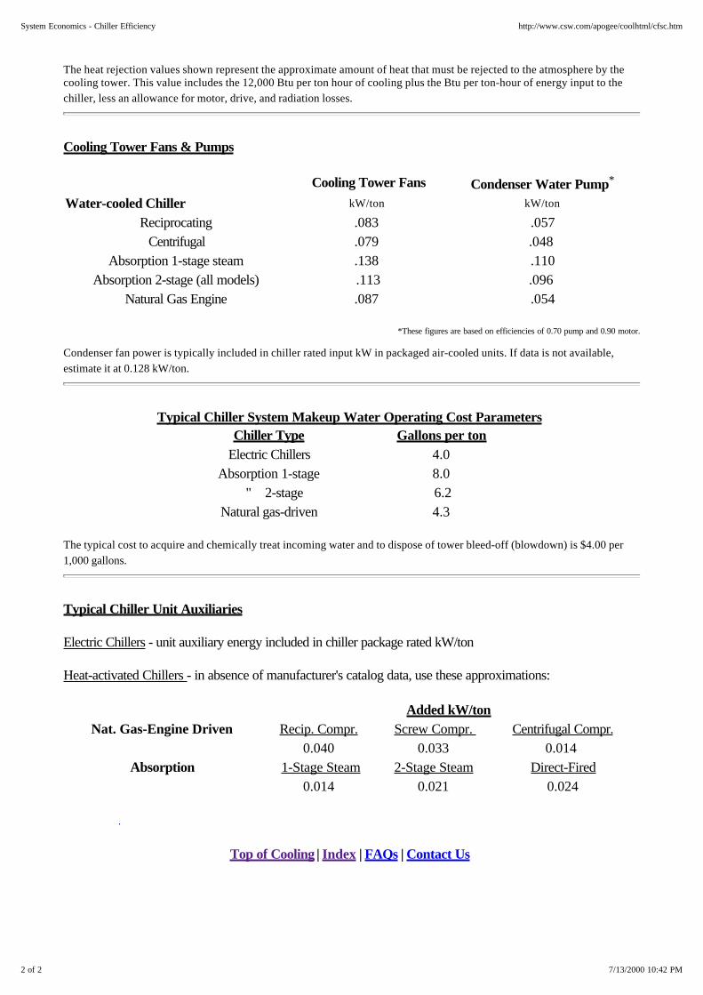
The heat rejection values shown represent the approximate amount of heat that must be rejected to the atmosphere by thecooling tower. This value includes the 12,000 Btu per ton hour of cooling plus the Btu per ton-hour of energy input to thechiller, less an allowance for motor, drive, and radiation losses.
Cooling Tower Fans & Pumps
Cooling Tower Fans Condenser Water Pump*
Water-cooled Chiller kW/ton kW/ton
Reciprocating .083 .057Centrifugal .079 .048
Absorption 1-stage steam .138 .110Absorption 2-stage (all models) .113 .096
Natural Gas Engine .087 .054
*These figures are based on efficiencies of 0.70 pump and 0.90 motor.
Condenser fan power is typically included in chiller rated input kW in packaged air-cooled units. If data is not available,estimate it at 0.128 kW/ton.
Typical Chiller System Makeup Water Operating Cost Parameters Chiller Type Gallons per ton
Electric Chillers 4.0 Absorption 1-stage 8.0
" 2-stage 6.2Natural gas-driven 4.3
The typical cost to acquire and chemically treat incoming water and to dispose of tower bleed-off (blowdown) is $4.00 per1,000 gallons.
Typical Chiller Unit Auxiliaries
Electric Chillers - unit auxiliary energy included in chiller package rated kW/ton
Heat-activated Chillers - in absence of manufacturer's catalog data, use these approximations:
Added kW/tonNat. Gas-Engine Driven Recip. Compr. Screw Compr. Centrifugal Compr.
0.040 0.033 0.014 Absorption 1-Stage Steam 2-Stage Steam Direct-Fired
0.014 0.021 0.024
Top of Cooling | Index | FAQs | Contact Us
2 of 2 7/13/2000 10:42 PM
System Economics - Chiller Efficiency http://www.csw.com/apogee/coolhtml/cfsc.htm

System Economics - Running Hours
The term Running Hours refers to the number of hours a year the chiller operates to meet the indoor designconditions. This usually refers to the number of hours cooling is required over the course of a year while thebuilding is occupied or the enterprise is otherwise in use. The chiller auxiliaries plus the condenser water pumpand tower fan will normally operate this number of hours. These hours vary by building type and geographicallocation. For example, an office building might have running hours that look like this:
Location Total running time - hr/yearMiami Atlanta Newark Chicago
3450270023002000
A hospital, operating 24hrs. per day, would probably have over twice these hours.
Top of Cooling | Index | FAQs | Contact Us
1 of 1 7/13/2000 10:43 PM
System Economics - Running Hours http://www.csw.com/apogee/coolhtml/cfsr.htm
System Economics - Equivalent FullLoad Hours
Equivalent Full Load Hours (EFLH): Even though a chiller is selected to supply the design load (100% or fullload), it does not operate at full load for very many hours out of the year. For example many chillers operatefor three quarters of each cooling season at 60% or less of design capacity. A chiller's part load efficiency hasa significant effect on operating costs.
EFLH is defined as the annual ton-hours of cooling actually supplied divided by the supplying chiller's designcapacity in tons. Using EFLH for analysis purposes is valid where the chiller plant has published continuous,performance values for energy input at all operating levels of output. Normally most centrifugal, screw, andabsorption chillers fit this operating profile. However, reciprocating compressor chillers do not have thiscontinuous performance characteristic, due to their step capacity operation and lower efficiency at part load.Therefore, their EFLH must be calculated using a more detailed procedure.
The load calculations for most buildings are performed using a personal computer. These calculations normallyestablish the running hours per year and enable the designer to estimate a building load profile. A sampleannual load profile might look like this:
Annual Load Profile Percent load
90% to 100% 81% to 90% 71% to 80% 61% to 70% 51% to 60% 41% to 50% 31% to 40% 21% to 30% 11% to 20%
0 to 10%
Percent running Hrs
2% 3 5
15 30 20 15 5 2
100%
The expected EFLH can be projected using a buildings estimated load profile and total annual running hours.For example, using this load profile and an assumed 2,300 running hours, the EFLH can be calculated to be1,277. If this chiller had a design capacity of 500 tons, it would deliver an estimated 638,500 ton-hrs ofcooling (500 tons x 1,277 Equivalent Full Load Hours). PC-based energy analysis tools, including EPRI'sCOMTECH and APOGEE's chiller screening program, can perform this type of analysis very handily.
1 of 2 7/13/2000 10:43 PM
System Economics - Equivalent Full Load Hours http://www.csw.com/apogee/coolhtml/cfsf.htm
System Economics - Operating Hoursand EFLH
Chillers do not normally operate every hour of the year, and may not always operate when the building isoccupied. There are days when outside air alone can supply the necessary cooling, and most chillers willrequire some periodic maintenance during the year even when the chiller could be running (where coolingwould be supplied by other equipment during this period). For example, office buildings in the northernclimates might call for a chiller to operate 1,000 hours a year while chillers in buildings along the Gulf Coastprobably operate more than half the time the building is open.
In very humid areas, chillers may have to operate even when the building is unoccupied just to maintainhumidity levels. On the other hand, hospital operating rooms often require chiller operation every month of theyear (although not necessarily every day).
Obviously then, a chiller does not always operate at full load. If the chiller were to meet the annual cooling loadby operating only at full load and then cycling off, it would end up operating fewer annual hours. These aredefined as Effective Full Load Hours (EFLH) and typically make up about half of the annual operating hours.Therefore, a building that might operate a chiller for 2000 hours in colder climates for general spaceconditioning should typically expect about 1000 EFLH for that chiller.
Top of Cooling | Index | FAQs | Contact Us
1 of 1 7/13/2000 10:53 PM
System Economics - Operating Hours and EFLH http://www.csw.com/apogee/coolhtml/cfso.htm
System Economics - Installed Costs
Installed costs and capital offsets are important economic parameters. The installed cost of electric chillers issignificantly lower than comparable heat-driven chillers. Heat-driven Chillers require larger cooling waterpumps and towers. Engine driven chillers have a prime mover that costs much more than a comparable electricmotor (and has much higher maintenance costs as well). Absorption chillers are much more costly thancomparable sized electric chillers.
While the factory price of a chiller unit may be easy to obtain, a more meaningful economic comparison isbased on the estimated total installed cost. This figure should include the chiller plus associated cooling towerand condenser water pumps and piping or air-cooled condenser, plus delivery of the equipment to the job site,and installation with interconnecting tower/chiller/pump piping and controls, including the contractor's overheadand profit.
Where any one cost segment is constant for all alternatives (such as chilled water distribution pumps andpiping), this cost can be omitted since it will not affect the outcome comparison. In some cases, thecomparison is simplified if incremental costs are used; that is, one chiller is considered the base and the otheralternatives are assessed at how much more or less they cost. For example if one chiller requires 100 morekW service than another, than the incremental service cost is estimated at $45/kW. That chiller's incrementalcost would be $4,500 more than the base unit's cost.
In the absence of current, project specific, installed cost figures, information in the Compare Section can beused to estimate costs.
Select from these areas of interest . . .
Compare - Installed Costs - Chillers
Top of Cooling | Index | FAQs | Contact Us
1 of 1 7/13/2000 10:54 PM
System Economics - Installed Costs http://www.csw.com/apogee/coolhtml/cfsn.htm

Compare - Installed Costs - Chillers
Installed costs and capital offsets are important economic parameters. The installed cost of electric chillers issignificantly lower than comparable heat-driven chillers. Heat-driven Chillers require larger cooling waterpumps and towers. Engine driven chillers have a prime mover that costs much more than a comparable electricmotor (and has much higher maintenance costs as well). Absorption chillers are much more costly thancomparable sized electric chillers.
While the factory price of a chiller unit may be easy to obtain, a more meaningful economic comparison isbased on the estimated total installed cost. This figure should include the chiller plus associated cooling towerand condenser water pumps and piping or air-cooled condenser, plus delivery of the equipment to the job site,and installation with interconnecting tower/chiller/pump piping and controls, including the contractor's overheadand profit.
Where any one cost segment is constant for all alternatives (such as chilled water distribution pumps andpiping), this cost can be omitted since it will not affect the outcome comparison. In some cases, thecomparison is simplified if incremental costs are used; that is, one chiller is considered the base and the otheralternatives are assessed at how much more or less they cost. For example if one chiller requires 100 morekW service than another, than the incremental service cost is estimated at $45/kW. That chiller's incrementalcost would be $4,500 more than the base unit's cost.
In the absence of current, project specific, installed cost figures, these charts and tables can be used toestimate and compare costs.
The costs shown are typical of large water chiller installed costs including cooling tower with pump piping andinstallation or air-cooled condenser. They are at nominal tons capacity and HCFC-123 or HFC-134acompatible.
Electric Reciprocating Chillers - Air - and Water-Cooled Electric Centrifugal/Screw Chillers - Water-Cooled Absorption & Engine Drive Chillers - Water-Cooled
1 of 3 7/14/2000 10:25 AM
Compare - Installed Costs - Chillers http://www.csw.com/apogee/coolhtml/cmnch.htm

The values provided reflect new construction in a typical building in a representative U.S. city with median
2 of 3 7/14/2000 10:25 AM
Compare - Installed Costs - Chillers http://www.csw.com/apogee/coolhtml/cmnch.htm

labor rates. For units larger than 1,000 tons, the installed cost per ton declines only slightly on a dollar per tonbasis. Costs shown are mid-1995 estimates for a single package chiller. On many installations, multiple units ofequal or mixed capacities are used. Again, location, labor rates, rigging, control options, and unit efficiency cansubstantially affect the actual installed cost, which can vary as much as +25%.
Some gas suppliers will subsidize the higher installed costs of engine-driven and absorption chillers. One waythey do this is to absorb a percentage of the cost premium. Others will offer incentives, anywhere from $100to $150 or more per ton, to reduce the installed cost premium. There is no way to be certain how long theseincentives may continue.
Top of Cooling | Index | FAQs | Contact Us
3 of 3 7/14/2000 10:25 AM
Compare - Installed Costs - Chillers http://www.csw.com/apogee/coolhtml/cmnch.htm

System Economics - Owning Costs
Owning costs are another component in the economic analysis. The cost of financing, the value of the moneyinvested, depreciation, and income taxes should be factored into the equation. Any money invested in apremium priced chiller system has a value. Whether that money is borrowed or not, it represents an"opportunity cost" equivalent to a fixed interest rate. Therefore this cost is a proper part of the total coolingsystem owning and operating cost.
In the following formula that expresses the value of money, the interest rate "i" is stated as a decimal, and theamortization period ("n" years) determine the uniform annual charge to pay back the initial investment. This iscalled the Capital Recovery Factor (CRF):
CR°F = (1+ i)n x i (1 + i)n - 1
The initial investment times the CRF represents the annual "mortgage" payment to retire the investment in "n"years. For monthly payments, divide "i" by 12 and multiply "n" by 12.
Tables are available that provide these values. More sophisticated hand calculators even feature function keysto perform this calculation. Simply use the appropriate interest rate. A 20 year term is not uncommon.
Federal and State income taxes are levied on net income. Annual savings of one alternative over another areconsidered taxable income, since these savings increase a firm's net income.
Depreciation allowances are subtracted from the net savings and may "shelter" the owner from certain incometax consequences. A tax accountant can handle the computations for this segment of the economic analysis.
Insurance and property taxes are assessed as equipment installations increase the tax base of the property. Thechiller system should also be covered by fire and liability insurance, which add to the policy's annual premium.In the absence of other information, an annual premium of 1 to 2% of the first cost cover these annual costs.
Replacement provisions should be considered where applicable. The service life is the median time duringwhich a particular chiller system or component remains in service before it is replaced. The service life may ormay not be the same as the depreciation or economic evaluation periods.
In the 1995 ASHRAE Applications Handbook Chapter 33 - "Owning and Operating Costs" - Table 3indicates the service life doesn't vary much for most chillers. To omit this refinement would not significantlyaffect your evaluation.
The major components of a chiller that are likely to need replacement the end of the service life include:
The condenser, which is likely to need retubing, The absorption chiller absorber, which is likely to need retubing, The natural gas engine which typically requires a major overhaul at between 8,000 to 24,000 operating
1 of 2 7/13/2000 10:54 PM
System Economics - Owning Costs http://www.csw.com/apogee/coolhtml/cfsw.htm

System Economics - EvaluatingAlternatives
Procedures for evaluating alternatives vary widely, ranging from simple payback to complicatedcomputer-generated life cycles. There are numerous computer-generated programs, including EPRl'sCOMTECH screening tool, that can estimate "life-cycle costs" by running the analysis for a 15 to 20-year timeperiod and include varying inflationary effects on fuel, power and O&M costs, taxes, depreciation, andsalvage.
Use the more complex techniques cautiously. Future costs of fuels and electricity are very difficult to project,and these estimates have often proved wrong in the past. Remember when the "experts" were forecasting$100 a barrel oil in the 1980s? Be wary of any cash flow analysis indicating that the benefits only look good inthe future - it simply may not happen!
Top of Cooling | Index | FAQs | Contact Us
1 of 1 7/13/2000 10:55 PM
System Economics - Evaluating Alternatives http://www.csw.com/apogee/coolhtml/cfsa.htm
System Economics - Integrated PartLoad Value (IPLV)
Large chillers, whether they're electric or heat activated, usually perform the best when they are operatingbetween 30% and 90% of their full load design. When these energy per ton figures are linked to the typicalhourly load profile, the chiller's annual power consumption becomes more meaningful. This effect is called"Integrated Part Load Value". IPLV was introduced in the 1990 revision of ARI Standard 550, which governsthe rating and testing of centrifugal and screw water chillers.
For an electric chiller, the integrated part load value in kW/ton on a weighted basis might be only 90.6% of thefull-load value of 0.70 kW/ton. In practice with a properly operated centrifugal or screw compressor chillerthis weighted power input will range from 85% to 91% of the full-load kW/ton. A similar factor applies to anabsorption chiller's full load Btu per ton hour fuel energy input.
Top of Cooling | Index | FAQs | Contact Us
1 of 1 7/13/2000 10:55 PM
System Economics - Integrated Part Load Value (IPLV) http://www.csw.com/apogee/coolhtml/cfsi.htm

System Economics - Operating andMaintenance Costs
Operating and maintenance costs include the day-to-day costs keeping the equipment running. It is wise tokeep these estimates on the conservative side since the economic analysis will contribute to a prudent financialjudgment. This is not the place for optimism. Operating costs depend largely on the relative electric and gasrates. It is vital that the demand charges and energy costs of each alternative be calculated separately andconsider any seasonal or time-of-use provisions. Never use "average rates."
Building codes or other considerations may dictate the need for operating personnel. If this is the case,personnel costs must be included. And don't forget to add the energy and water prices to the energyconsumption rate of each chiller alternative on a "level playing field" basis. Maintenance costs for screw andcentrifugal chillers are typically lower than for absorption chillers, since absorbers require more frequentreplacement of mechanical components, tube stresses are higher, and there are simply more tubes to replace.Costs for engine-driven chillers are even higher since they require engine maintenance in addition to the samemaintenance costs as an electric chiller.
Natural Gas Engine-Driven Chiller Maintenance Issues
With natural gas engine-driven chillers, engine maintenance is a costly item. The engine vibrations affect tubebundles and compressor shaft seals. Higher speed (3,600 rpm) engines are less reliable than lower speed(1,200 rpm) engines. All spark-ignited natural gas engines used on chillers require periodic service, (includingspark plug and lubrication oil changes) every 500 to 750 hours of service. The technicians that would normallyservice the chiller may not be qualified to service the engine. Multiple vendor responsibilities between theengine, controls, and chiller suppliers tends to complicate maintenance. In addition, environmental legislation islikely to mandate emission controls which current engines may not be able to meet.
Engine maintenance is directly proportional to the operating (running) hours per year. Depending on the engine,a major overhaul or engine replacement will be needed after a certain number of hours. This typically rangesfrom 8,000 hours on the relatively high-speed 3,600 rpm automotive-type engines to 24,000 hours on 1,200rpm industrial-grade engines. The engine maintenance cost should be added to the maintenance costs of a likecapacity electric chiller and include complete engine-only service plus a sinking fund for overhaul and enginereplacement.
Natural gas engine maintenance costs typically range from $0.006 to $0.020 per ton; the average is $0.012per ton per operating hour. Add the engine maintenance cost ($ per ton per operating hour x chiller capacity xoperating hours per year) to the maintenance costs of a similarly sized electric chiller ($ per ton-year x chillertons capacity). This total will include the chiller and the full service and replacement cost of the engine.
Preventive Maintenance
With the rising costs of energy and refrigerants, plus the added concern about the environment, proper ongoingand preventive maintenance of chilling equipment makes good sense. In most areas there are competent
1 of 2 7/13/2000 10:54 PM
System Economics - Operating and Maintenance Costs http://www.csw.com/apogee/coolhtml/cfsm.htm

independent- or manufacturer-operated service agencies who can provide this maintenance under contract.Owners or building managers with a large inventory of equipment may choose to employ their own personnel.In all cases, technicians should be well trained in the equipment serviced and stay up-to-date through periodicretraining.
For accurate economic comparisons, obtain local service contract quotations on the various alternatives.Lacking actual quotations, this table provides estimates of the annual dollars per installation for single chillerinstallations including the cooling tower and condenser water pump. These figures are based on median laborrates and no significant travel time. These values also include an allowance for materials and supplies.
Multiple Units
For multiple units at a single location, make the calculation as if the units were singly installed and multiply thetotal dollar chiller only maintenance cost of all units (not including gas engine maintenance) by a 0.80 multiplierfor two units at single location, or a 0.70 multiplier for three or more units at single location. For engine-drivenchillers, add in the engine-only maintenance costs.
Select from these areas of interest . . .
System Economics - Operating and Maintenance Costs - Chillers
Top of Cooling | Index | FAQs | Contact Us
2 of 2 7/13/2000 10:54 PM
System Economics - Operating and Maintenance Costs http://www.csw.com/apogee/coolhtml/cfsm.htm
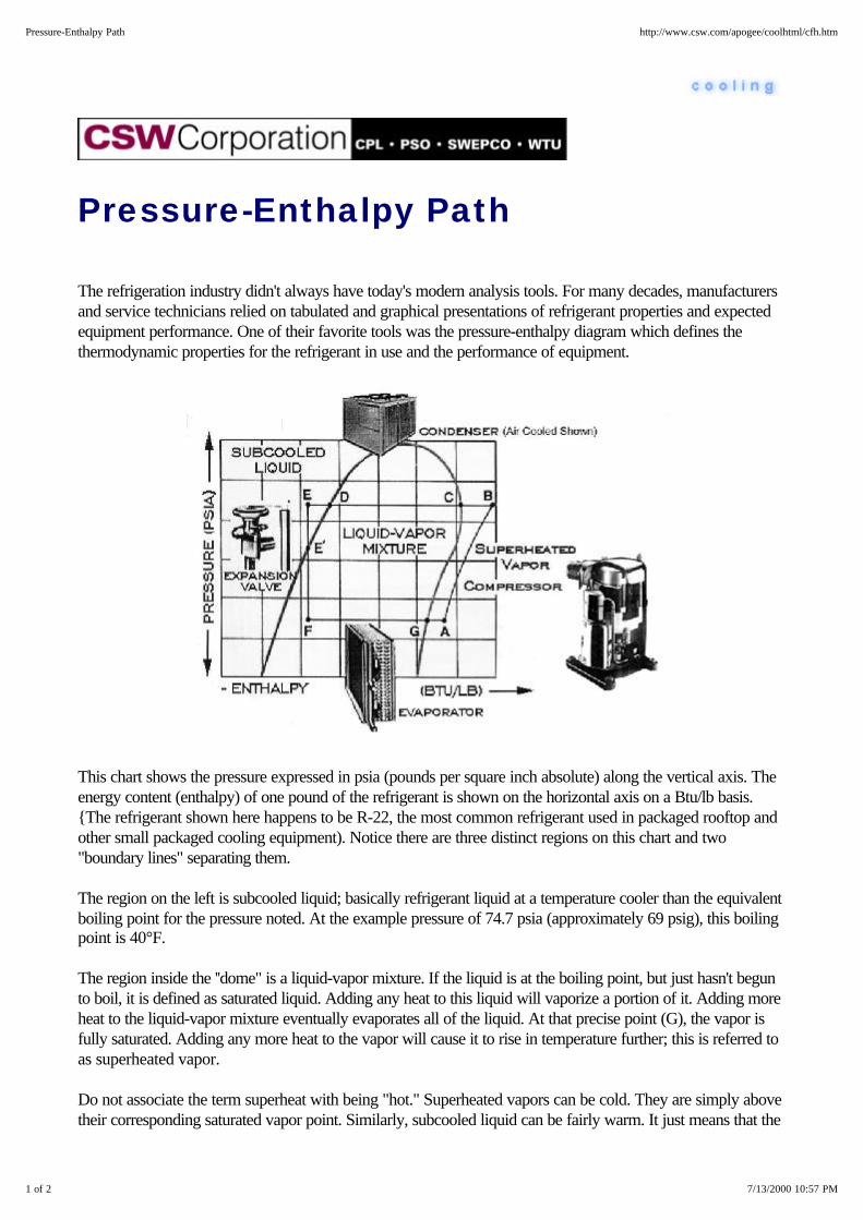
Pressure-Enthalpy Path
The refrigeration industry didn't always have today's modern analysis tools. For many decades, manufacturersand service technicians relied on tabulated and graphical presentations of refrigerant properties and expectedequipment performance. One of their favorite tools was the pressure-enthalpy diagram which defines thethermodynamic properties for the refrigerant in use and the performance of equipment.
This chart shows the pressure expressed in psia (pounds per square inch absolute) along the vertical axis. Theenergy content (enthalpy) of one pound of the refrigerant is shown on the horizontal axis on a Btu/lb basis.{The refrigerant shown here happens to be R-22, the most common refrigerant used in packaged rooftop andother small packaged cooling equipment). Notice there are three distinct regions on this chart and two"boundary lines" separating them.
The region on the left is subcooled liquid; basically refrigerant liquid at a temperature cooler than the equivalentboiling point for the pressure noted. At the example pressure of 74.7 psia (approximately 69 psig), this boilingpoint is 40°F.
The region inside the ''dome" is a liquid-vapor mixture. If the liquid is at the boiling point, but just hasn't begunto boil, it is defined as saturated liquid. Adding any heat to this liquid will vaporize a portion of it. Adding moreheat to the liquid-vapor mixture eventually evaporates all of the liquid. At that precise point (G), the vapor isfully saturated. Adding any more heat to the vapor will cause it to rise in temperature further; this is referred toas superheated vapor.
Do not associate the term superheat with being "hot." Superheated vapors can be cold. They are simply abovetheir corresponding saturated vapor point. Similarly, subcooled liquid can be fairly warm. It just means that the
1 of 2 7/13/2000 10:57 PM
Pressure-Enthalpy Path http://www.csw.com/apogee/coolhtml/cfh.htm

liquid is cooler than the saturation line for that pressure.
The typical refrigeration cycle is shown superimposed on this chart, along with pictures of the typical equipmentcomponents associated with that step in the cycle.
Let's start our review at point A. To get this point after leaving the evaporator (G), the refrigerant vapor issuperheated slightly, and crosses the compressor suction valve to point A. The compressor elevates therefrigerant's pressure to a point at which it can push the discharge valve open and flow to in the condenser. Therefrigerant vapor leaves the compressor at point B, desuperheats to point C, and then begins to condense.After the vapor is completely condensed at point D, it is subcooled a bit further (E), at which time is still at amuch higher pressure than the evaporator.
Controlling the flow to the evaporator and throttling this pressure to that of the evaporator is the job performedby the expansion device, a thermal expansion (TX) valve in this illustration. This pressure reduction stepvaporizes a portion of the liquid which cools (called flash gas) the remaining liquid going to point F -- the"average" mixture of vapor and liquid crossing the valve doesn't change in energy content -- it simply separatesinto liquid and vapor at the reduced temperature and pressure according to its precise thermodynamicproperties. The liquid at point F is then ready to pick up heat in the evaporator and form vapor at point Gwhere the cycle repeats.
Each step in this process follows precise thermodynamic laws.
Top of Cooling | Index | FAQs | Contact Us
2 of 2 7/13/2000 10:57 PM
Pressure-Enthalpy Path http://www.csw.com/apogee/coolhtml/cfh.htm
System Performance Measures
Performance of Electric Systems
Performance of Fueled Systems
Top of Cooling | Index | FAQs | Contact Us
1 of 1 7/13/2000 10:58 PM
System Performance Measures http://www.csw.com/apogee/coolhtml/cxfm.htm

Performance of Electric Systems
Since the vast majority of cooling equipment is driven with electric motors, the most common performancemeasure is kW/ton. This can be calculated for any given chiller by simply taking the manufacturer's estimatedpower use and dividing it by the cooling system capacity expressed in tons. For example, if the manufacturerestimates the peak power required for a 250 ton chiller is 150 kW, the chiller will use 150 kW/250 tons or 0.6kW/ton on the design day.
But what is included in this 150 kW? Is it the chiller alone, or the pumps and fans in the remainder of thesystem? If this power estimate was for a packaged rooftop unit supplying air to the building, the powerestimate is clearly the total kW/ton. However, in buildings where a centrally located water chiller is used, thereare also chilled water and condenser water pumps as well as cooling tower fans. Were these included in thekW/ton performance measure? Not usually! And, in these cases, they must be added in to get the total kWper ton performance.
Design professionals usually evaluate chiller performance by comparing kW/ton for the chiller itself plus theheat rejection circuit. After all, for any given building, the chilled water distribution system alternatives would beidentical. The differences between low and high efficiency cooling system alternatives shows up in the kW/tonfor the chiller plus the heat rejection circuit. Therefore, use this total when comparing the kW/ton for chilleralternatives such as:
1. Air cooled versus water cooled
2. Low vs. high efficiency
3. Gas vs. electric driven (since gas equipment also has electrical requirements).
Obviously, gas equipment also has fuel consumption which should be factored into the comparison.
So far, we have compared equipment on the design day -- the relatively few hottest and/or most humid days inyour area. These are certainly important in determining the electrical demand charges. But, in most parts of theUnited States, these conditions occur only a few hours a year. It is true they may occur one or more days ineach of the warmest months (and thereby set a demand charge for those months), but this still doesn'trepresent the most common operating environment.
The HVAC industry recognized this and characterized these more common situations using the Integrated PartLoad Value (IPLV) which is a defined number of hours at representative chiller operating conditions based onan ARI standard, Actual Part Load Value (APLV) is determined by the design community for the specificbuilding situation at hand.
The specific kW/ton performance for each type of electric (and fuel-fired) system is discussed in the specificsegment on that chiller design. Suffice it to say that most large cooling systems become more efficient at partload conditions, while small reciprocating compressor systems become less efficient at typical part loadconditions.
1 of 2 7/13/2000 10:58 PM
Performance of Electric Systems http://www.csw.com/apogee/coolhtml/cxfme.htm

Select from these areas of interest . . .
Coefficient of Performance (COP) for Electric Systems Energy Efficiency Ratio (EER) and Seasonal Energy Efficiency Ratio
Heating Season Performance Factor (HSPF)
Top of Cooling | Index | FAQs | Contact Us
2 of 2 7/13/2000 10:58 PM
Performance of Electric Systems http://www.csw.com/apogee/coolhtml/cxfme.htm

Coefficient of Performance (COP) forElectric Systems
The term Coefficient of Performance (COP) is simply the ratio of the cooling effect produced expressed inBtu/hr divided by the energy input expressed on the same basis. For an electric chiller at 0.6 kW/ton, this ratiois 12,000 Btu for a ton of cooling divided by the corresponding 0.6 kW energy input. The units of kW canbest be thought of as kW hours per hour. Each kW is equivalent to 3,413 Btu, therefore 0.6 kW is 2,048 Btu.Therefore, a 0.6 kW/ton chiller is equivalent to a COP of 12,000 Btu/2,048 Btu, about 5.9 COP. Notice theterm COP is dimensionless.
There is a short-cut formula to compute COP directly from any given kW/ton. Simply divide 3.516 by thechiller's kW/ton to derive COP. (3.516 comes from dividing 12,000 Btu by 3413 Btu per kWh). Forexample, 3.516/0.6 is the same ~ 5.9 COP as before. Be careful when comparing cooling system COPs to besure exactly what is being included. A fair comparison includes the full heat rejection circuit as well.
Top of Cooling | Index | FAQs | Contact Us
1 of 1 7/13/2000 10:59 PM
Coefficient of Performance (COP) for Electric Systems http://www.csw.com/apogee/coolhtml/cfmec.htm
Energy Efficiency Ratio (EER) andSeasonal Energy Efficiency Ratio(SEER)
The cooling equipment systems used in residential and small commercial buildings often express cooling systemefficiency in terms of the Energy Efficiency Ratio (EER) and/or Seasonal Energy Efficiency Ratio (SEER).These are defined by the cooling effect (in Btu -- not tons) divided by the power use (in watts -- not kW) forthe peak day (EER), or the seasonal average day (SEER). For example, a small cooling unit operating at 1kW /ton would have an EER of 12,000 Btu divided by 1000 watts -- or 12. This is mathematically equivalentto multiplying the COP by 3.413, or visa, versa. Therefore a small cooling unit operating at 1 kW (1000 watts)per ton is equivalent to a COP of 3.516, or an EER of 12.
Top of Cooling | Index | FAQs | Contact Us
1 of 1 7/13/2000 10:59 PM
Energy Efficiency Ratio (EER) and Seasonal Energy Efficiency Ratio (SEER) http://www.csw.com/apogee/coolhtml/cfmee.htm

Heating Season Performance Factor(HSPF)
Heat pump systems that produce cooling during the summer and then switch over to produce heating duringthe winter use a similar performance measure. Here, the Heating Season Performance Factor (HSPF) isdefined by the heating effect (in Btu) divided by the power use for the seasonally averaged condition. A keypoint here is that the heating effect in a heat pump includes the work input since the system is using the heatrejection side of the cycle to produce useful space conditioning. This is not true during the cooling cycle (unlessa heat recovery heat-pump design is being implemented).
Top of Cooling | Index | FAQs | Contact Us
1 of 1 7/13/2000 10:59 PM
Heating Season Performance Factor (HSPF) http://www.csw.com/apogee/coolhtml/cfmeh.htm

Performance of Fueled Systems
Absorption, desiccant, and engine-driven cooling systems have energy performance measures similar toelectrically driven equipment. They also use power in controls, circulating pumps, and heat rejection systemsthat should be factored into any energy and economic comparisons. You can review all these performancecharacteristics by investigating the specific cooling system design alternative(s). The discussion here simplyhighlights the definitions for fueled system performance.
Select from these areas of interest . . .
Coefficient of Performance (COP) with Fueled Systems Higher Heating Value (HHV) and Lower Heating Value (LHV)
Top of Cooling | Index | FAQs | Contact Us
1 of 1 7/13/2000 11:00 PM
Performance of Fueled Systems http://www.csw.com/apogee/coolhtml/cxfmf.htm

Coefficient of Performance (COP) withFueled Systems
The term Coefficient of Performance (COP) is the ratio of the cooling effect produced expressed in Btu/hrdivided by the energy input expressed on the same terms. And, there is no standard for comparison betweendifferent manufacturers. Therefore, the potential user of this information should not use COP for comparisons.Most high efficiency, two-stage absorbers achieve a COP of ~1, that is, they use about 12,000 Btu of fuelenergy to produce one ton of cooling. However, the absorber has much higher heat rejection power use than acomparable electric driven machine. And these fueled systems also use electric energy for pumps, fans andcontrols. At this time, manufacturers generally do not count the power used in their COP performance data.
Top of Cooling | Index | FAQs | Contact Us
1 of 1 7/13/2000 11:00 PM
Coefficient of Performance (COP) with Fueled Systems http://www.csw.com/apogee/coolhtml/cfmfc.htm

Higher Heating Value (HHV) andLower Heating Value (LHV)
Natural gas is often selected as the fuel for these systems since supply disruptions during warmer months areunlikely. There are two ways to define the energy content of natural gas in common use -- Higher HeatingValue (HHV) and Lower Heating Value (LHV). The difference can be especially important when reviewingthe performance of engine-driven systems.
Higher Heating Values for a fuel include the full energy content as defined by bringing all products ofcombustion to 77°F (25° C). Natural gas typically is delivered by the local gas company with values of 1,000 -1,050 Btu per cubic foot on this HHV basis. Since the actual value may vary from month to month some gascompanies convert to Therms. A therm is precisely 100,000 Btu. These measures all represent higher heatingvalues.
Some engine manufacturers rate their engines using Lower Heating Values (LHV) which can be both confusingand potentially misleading to the casual user of their product literature. Lower heating values neglect the energyin the water vapor formed by the combustion of hydrogen in the fuel. This water vapor typically representsabout 10% of the energy content. Therefore the lower heating values for natural gas are typically 900 - 950Btu per cubic foot.
The error can occur when a manufacturer says their engine uses 900,000 Btu/hr but it was expressed on aLHV basis. The engine would actually use about 1,000,000 Btu/hr as purchased from a gas supplier.Therefore, always check the fuel rating method when natural gas is the fuel for the system. This potentialconfusion almost never exists with liquid fueled systems.
Top of Cooling | Index | FAQs | Contact Us
1 of 1 7/13/2000 11:00 PM
Higher Heating Value (HHV) and Lower Heating Value (LHV) http://www.csw.com/apogee/coolhtml/cfmfh.htm

Condenser Water Temperature &Flow
Chillers larger than about 100 tons usually have water circulating through the condenser. This water removesthe heat from the chiller (the contribution due to the cooling as well as removing the heat from the motor, engineor absorber). Therefore a high efficiency electric chiller rated at 0.6 kW per ton rejects approximately 14,000Btuh/ton of cooling. A high efficiency absorption chiller with a COP of 1.0 rejects about 24,000 Btuh/ton ofcooling.
The circulating cooling tower water flow is determined primarily by the range in temperature. For example,with a high efficiency electric chiller, a 10°F range (e.g., supplying 85°F water to the chiller condenser andheating that water to 95°F), requires a condenser water flow of about 2.8 gpm per ton. With the same 10°Frange, it would have to be about 4.8 gpm per ton for the high efficiency absorption chiller. This flow can bereduced by widening the range, but that would decrease the efficiency of the chiller itself.
The temperature of the water sent to the chiller condenser from the cooling tower is determined, largely by theambient wet bulb temperature and the efficiency of the cooling tower (the amount of air drawn through thetower and the efficiency of air-water contact). Dry bulb temperature has only a minimal impact on coolingtower performance. The cooling tower is normally specified to meet the design wet bulb temperature in anygeographic area -- commonly 75° to 78°F. The cooling tower manufacturer then designs the tower to produce85°F water under this condition for the design heat rejection level and water flow. The temperature differencebetween the water sent to the condenser (i.e. coming off the cooling tower) and this wet bulb figure (say 78°F)is defined as the approach temperature 7°F (= 85 - 78).
This design day wet bulb condition occurs relatively few hours a year in most parts of the United States.During dryer times, the cooling tower can produce colder water than 85°F. And, most chillers will operatewith reduced power input if this water temperature is reduced (down to a given limit as specified by theequipment manufacturer). This concept is called "floating the condenser" and holds the potential of conservingenergy and reducing operating costs.
Selecting the condenser water parameters and cooling tower design is very complicated. Design of thesesystems requires experience, careful analysis, and consideration of initial investment and operating costs. Thematerial presented here is simply an explanation of several design parameter opportunities. Please refer to thespecific cooling design modules elsewhere in this information system for additional details.
Formula: Btuh = gpm x range in °F x 500 where: 500 = 60min/hr x 8.33 lb/gal of water
Top of Cooling | Index | FAQs | Contact Us
1 of 1 7/13/2000 11:01 PM
Condenser Water Temperature & Flow http://www.csw.com/apogee/coolhtml/cfn.htm

Compressor Capacity andPerformance
All compressors are rated in terms of how much flow (e.g., acfm) they produce at a given ratio of outlet to inletpressure (compression ratio). This flow is obviously a function of compressor size (e.g., the number ofcylinders and volume displacement for recip compressors) and operating speed (rpm), Compression ratio isdefined by the discharge pressure divided by the suction pressure (both in absolute pressure, psia).
The limits of clearance volumes and valve pressure differentials force some of the compressor's flow volumecapability to be lost as useful compression. This is referred to as volumetric efficiency. For example, at acompression ratio of 3 to 1, 82% of the volume of the compressor is useful. Therefore, if the refrigerationeffect required 10 cfm of vapor flow from the evaporator, the compressor would have to produce 10/.82 or12.2 cfm of flow.
Top of Cooling | Index | FAQs | Contact Us
1 of 1 7/13/2000 11:02 PM
Compressor Capacity and Performance http://www.csw.com/apogee/coolhtml/cfp.htm

Cooling Comfort
People "feel comfortable" over a wide range of temperatures and conditions, depending upon age, weight, sex,and level of physical activity. A sedentary person could feel "cold" at 74°F if the humidity is low, while afactory worker could feel warm at 65°F if they are performing heavy manual labor. The HVAC systemdesigner usually has to make a compromise, and most design to accepted criteria for human comfort. Duringthe summer, interior office space is usually designed to hold a maximum temperature of 75°F and a relativehumidity of 50%. But, some areas of the country have very low humidity, even during these summer months.This means the space temperature could be set at 78-80°F and provide the same level of comfort.
The comfort levels are also dependent upon air movement. Someone sitting in a space with inadequate airmovement is likely to feel "closed in." A certain amount of fresh air must be introduced. This is defined byASHRAE standards for the building type and intended use.
ASHRAE standards provide CFM/person and CFM/sq.ft. guidelines.
Top of Cooling | Index | FAQs | Contact Us
1 of 1 7/13/2000 11:02 PM
Cooling Comfort http://www.csw.com/apogee/coolhtml/cff.htm

Cooling Systems
Top of Cooling | Index | FAQs | Contact Us
1 of 1 7/13/2000 11:10 PM
Cooling Systems http://www.csw.com/apogee/coolhtml/cxs.htm

Special Cooling System Designs
Special Cooling System Designs - Clean Rooms
Special Cooling System Designs - Data Processing
Special Cooling System Designs - Hospital Operating Rooms
Top of Cooling | Index | FAQs | Contact Us
1 of 1 7/13/2000 11:06 PM
Special Cooling System Designs http://www.csw.com/apogee/coolhtml/cxsc.htm
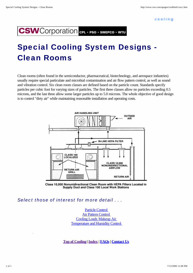
Special Cooling System Designs -Clean Rooms
Clean rooms (often found in the semiconductor, pharmaceutical, biotechnology, and aerospace industries)usually require special particulate and microbial contamination and air flow pattern control, as well as soundand vibration control. Six clean room classes are defined based on the particle count. Standards specifyparticles per cubic foot for varying sizes of particles. The first three classes allow no particles exceeding 0.5microns, and the last three allow some larger particles up to 5.0 microns. The whole objective of good designis to control "dirty air" while maintaining reasonable installation and operating costs.
Select those of interest for more detail . . .
Particle Control Air Pattern Control
Cooling Loads Makeup Air Temperature and Humidity Control
Top of Cooling | Index | FAQs | Contact Us
1 of 1 7/13/2000 11:08 PM
Special Cooling System Designs - Clean Rooms http://www.csw.com/apogee/coolhtml/cxscc.htm

Clean Rooms - Temperature andHumidity Control
Precise temperature and humidity control are required. Temperature tolerances within 1°F are common, 0.1 to0.5°F required in some applications. In most Class 1000 or better clean rooms, production personnel wear fullcoverage smocks. Comfort dictates room temperatures of 68°F or less. In other situations, processtemperatures set the control point.
Many clean rooms have relative humidity levels varying from 30 to 50 percent. Again, process requirementsset the degree of control with tolerances varying from 0.5 to 5 percent relative humidity.
Static electricity problems are less with humidities approaching 50%.
Top of Cooling | Index | FAQs | Contact Us
1 of 1 7/13/2000 11:12 PM
Clean Rooms - Temperature and Humidity Control http://www.csw.com/apogee/coolhtml/cscct.htm

Clean Rooms - Particle Control
Particle control addresses particles from both external and internal sources. Most external particles can beprevented from entering conditioned space with proper filtration. Two varieties of high efficiency air filters areavailable - High Efficiency Particulate Air filters (HEPA) and Ultra Low Penetration Air filters (ULPA). HEPAfilters have efficiencies of 99.97 to 99.997 percent for particles 0.3 m and larger. ULPA filters are 99.9997percent efficient for particles down to 0.12 m in size. Both use glass fiber paper technology, although airionization technology is sometimes used to control the deposit of particles on product surfaces.
Ultraviolet germicidal irradiation (UVGI) can be used as a supplement to HEPA and ULPA filters.
Top of Cooling | Index | FAQs | Contact Us
1 of 1 7/13/2000 11:10 PM
Clean Rooms - Particle Control http://www.csw.com/apogee/coolhtml/csccp.htm

Clean Rooms - Air Pattern Control
Air pattern control refers to the process of minimizing air turbulence. Air supply and return configurations,people traffic, and process equipment layout all affect this air flow. Depending on specific needs, air flow isdesigned to be either unidirectional or non-unidirectional. Unidirectional airflow is characterized by a singlepass in a single direction through the clean room. Air velocity of 90 feet per minute is widely accepted as anorm.
Top of Cooling | Index | FAQs | Contact Us
1 of 1 7/13/2000 11:11 PM
Clean Rooms - Air Pattern Control http://www.csw.com/apogee/coolhtml/cscca.htm

Clean Rooms - Cooling Loads
Cooling loads in clean rooms are governed largely by process equipment and fan energy, since clean roomsare usually located entirely within conditioned space. Fan energy tends to be a rather large heat sourcebecause of the large airflow requirements. Recirculated airflow rates of 90 cfm per sq ft, which equates to 600air changes per hour, are typical in Class 100 or better rooms. The primary latent load is makeup airdehumidification with a low dry-bulb leaving air temperature (between 35 to 45°F) to achieve the relativelylow humidity requirements of many processes.
Top of Cooling | Index | FAQs | Contact Us
1 of 1 7/13/2000 11:12 PM
Clean Rooms - Cooling Loads http://www.csw.com/apogee/coolhtml/csccl.htm

Special Cooling System Designs -Data Processing Data processing areas may have special temperatureand humidity requirements. Because they typically havelonger operating hours, they may be served a separaterefrigeration and air-side system.
Data processing areas house computers as well asancillary equipment, such as printers. Computersgenerate significant heat and have components that arevery sensitive to extremes of temperature, humidity anddust. Computer rooms don't necessarily require quickresponse to changes but overall system reliability isessential. Computer rooms are usually kept at thelower end of the temperature tolerance of 72 ± 2°Ffor two reasons: 72°F generally assures satisfactoryoperation, and it provides a cushion for short-termpeak load temperature rise without adversely affectingcomputer operation.
The relative humidity should be around 50 percent ±5%, and filtration should catch 45% of the particulateswith a minimum of 20 percent. The direct supply of airto a computer should remove heat to no cooler than 60°F with a 65% relative humidity maximum and a 45%level of filtration quality.
And Furthermore . . .
Data Processing - Cooling Loads Data Processing - Air Conditioning Systems
Data Processing - Supply Air
Top of Cooling | Index | FAQs | Contact Us
1 of 1 7/13/2000 11:11 PM
Special Cooling System Designs - Data Processing http://www.csw.com/apogee/coolhtml/cxscd.htm

Data Processing - Cooling Loads
Cooling loads stem from the equipment, which is highly concentrated and not distributed too uniformly. Heatgain from lights should be no greater than for good quality office space; occupancy loads will be low tomoderate. Heat gains will be also be affected by room location. Because of the relatively low personneloccupancy and low proportion of outdoor air, computer room heat gains are largely sensible loads. A sensibleheat ratio of 0.9 or higher is common. Information on computer heat release can and should be obtained fromthe manufacturer.
Top of Cooling | Index | FAQs | Contact Us
1 of 1 7/13/2000 11:12 PM
Data Processing - Cooling Loads http://www.csw.com/apogee/coolhtml/cscdl.htm

Data Processing - Air ConditioningSystems
Air-conditioning systems should be installed so that the air-handling apparatus operates independently of therest of the HVAC equipment. It is often desirable to have them cross-connected for backup. A wide variety ofcombinations have been successfully used, including:
Complete self-contained packaged units within the computer room, Chilled water packaged units within the computer room, and served by remote chiller equipment, and Central station air-handling units with remote cooling equipment.
A separate and distinct refrigeration facility for the data processing area is often desirable because this area'sneeds are so different and often operates 24 hours a day the year round.. They require service andmaintenance without interfering with normal operation, and data processing must have the capability ofoperating on emergency power. Heat rejection equipment should be designed for worst case operatingconditions to prevent shutdown during worst case weather conditions.
Some computer equipment requires water cooling to maintain the equipment environment. The computerequipment manufacturer supplies this cooling system as part of its equipment, including a water-to-water heatexchanger that simply needs a supply of chilled water.
Top of Cooling | Index | FAQs | Contact Us
1 of 2 7/13/2000 11:13 PM
Data Processing - Air Conditioning Systems http://www.csw.com/apogee/coolhtml/cscda.htm
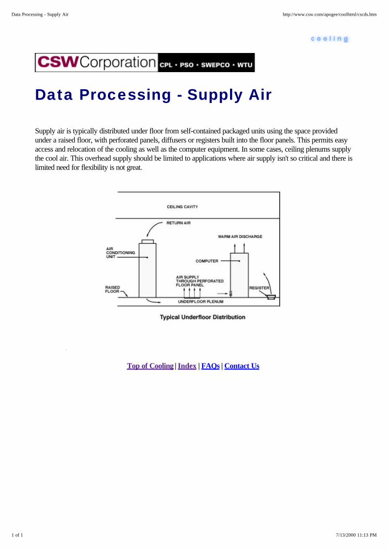
Data Processing - Supply Air
Supply air is typically distributed under floor from self-contained packaged units using the space providedunder a raised floor, with perforated panels, diffusers or registers built into the floor panels. This permits easyaccess and relocation of the cooling as well as the computer equipment. In some cases, ceiling plenums supplythe cool air. This overhead supply should be limited to applications where air supply isn't so critical and there islimited need for flexibility is not great.
Top of Cooling | Index | FAQs | Contact Us
1 of 1 7/13/2000 11:13 PM
Data Processing - Supply Air http://www.csw.com/apogee/coolhtml/cscds.htm

2 of 2 7/13/2000 11:13 PM
Data Processing - Air Conditioning Systems http://www.csw.com/apogee/coolhtml/cscda.htm
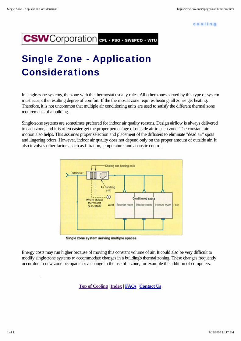
Single Zone - ApplicationConsiderations
In single-zone systems, the zone with the thermostat usually rules. All other zones served by this type of systemmust accept the resulting degree of comfort. If the thermostat zone requires heating, all zones get heating.Therefore, it is not uncommon that multiple air conditioning units are used to satisfy the different thermal zonerequirements of a building.
Single-zone systems are sometimes preferred for indoor air quality reasons. Design airflow is always deliveredto each zone, and it is often easier get the proper percentage of outside air to each zone. The constant airmotion also helps. This assumes proper selection and placement of the diffusers to eliminate "dead air" spotsand lingering odors. However, indoor air quality does not depend only on the proper amount of outside air. Italso involves other factors, such as filtration, temperature, and acoustic control.
Energy costs may run higher because of moving this constant volume of air. It could also be very difficult tomodify single-zone systems to accommodate changes in a building's thermal zoning. These changes frequentlyoccur due to new zone occupants or a change in the use of a zone, for example the addition of computers.
Top of Cooling | Index | FAQs | Contact Us
1 of 1 7/13/2000 11:17 PM
Single Zone - Application Considerations http://www.csw.com/apogee/coolhtml/cszc.htm

Fan Coil/Unit Ventilator Systems -Application Considerations
Fan coils or unit ventilators are typically installed around the perimeter of a building, on walls, under windowsor suspended in the ceilings. A mechanical equipment room on each floor is unnecessary. Perimeter sitingprovides easy access to outside air. However, in some cases, architecturally attractive grilles are used oroutside air can be introduced through a central shaft. Perimeter siting also makes it easier to run coil piping andcondensate drain connections to each unit.
Both unit ventilator and fan coil systems have filters and fan drive components that require periodicmaintenance. Service and maintenance could interrupt occupants. Therefore, ease of access is important whenspecifying either of these units.
Ventilation Air
If outside air is required, the unit will often have an outside air damper that mixes outside air with return airinside the unit cabinet. This also enables an air economizer cycle where air is used for cooling purposes. Airintake grilles on a building's exterior provide a path for outside air to enter the unit.
Top of Cooling | Index | FAQs | Contact Us
1 of 1 7/14/2000 8:15 AM
Fan Coil/Unit Ventilator Systems - Application Considerations http://www.csw.com/apogee/coolhtml/csfc.htm

Single Zone - Description
A single-zone system is best described as a constant volume, variable air temperature distribution a system. Asthe name implies, a single-zone system commonly serves one thermal zone or multiple zones with loads thatreact, at least thermally, in a similar manner.
This system features a fan moving a constant volume of air through a coil and into the zone. It may be a coolingor heating coil or both. The system airflow is usually equal to the sum of the individual peak air volumes in eachzone. The leaving air temperature is typically controlled by a single, adjustable thermostat centrally located inthe thermal zone.
An example of a common single-zone system is a single-zone rooftop. This is simply a packaged airconditioning unit with both air-side and refrigeration-side components in a common casing. It is made foroutdoor installation, and is typically installed, as the name would imply, on the building's roof. A rooftop unitdischarges air through ductwork and into the zones through diffusers. A thermostat is strategically located inone zone, and provides leaving air temperature control units. A building may have one or several rooftops unitsdepending on the number of zones or tenants, and the load and use characteristic of each zone.
Top of Cooling | Index | FAQs | Contact Us
1 of 1 7/13/2000 11:18 PM
Single Zone - Description http://www.csw.com/apogee/coolhtml/cszd.htm
Single Zone - Advantages
1. The major equipment is centrally located. This may permit operation and maintenance to take place inunoccupied areas.
2. This is a simple and relatively inexpensive system that provides conditioned air to a single zone.
3. There are no terminal units so potential disruption of the conditioned space is minimal.
Top of Cooling | Index | FAQs | Contact Us
1 of 1 7/13/2000 11:16 PM
Single Zone - Advantages http://www.csw.com/apogee/coolhtml/csza.htm

Single Zone - Disadvantages
1. It responds to only one set of space conditions, so it is limited to spaces where the thermal conditions varyuniformly
2. The constant volume airflow increases energy consumption.
The system is unable to take advantage of a buildings diversity which requires larger installed tonnage.
Top of Cooling | Index | FAQs | Contact Us
1 of 1 7/13/2000 11:18 PM
Single Zone - Disadvantages http://www.csw.com/apogee/coolhtml/cszv.htm

Fan Coil/Unit Ventilator Systems
Select one of these areas for more details. . .
Fan Coil/Unit Ventilator Systems - DescriptionFan Coil/Unit Ventilator Systems - Two-Pipe/Four-Pipe Systems
Fan Coil/Unit Ventilator Systems - Application Considerations
Differences Between Unit Ventilator and Fan Coil Systems
Fan Coil System AdvantagesFan Coil System Disadvantages
Unit Ventilator System AdvantagesUnit Ventilator System Disadvantages
1 of 2 7/13/2000 11:21 PM
Fan Coil/Unit Ventilator Systems http://www.csw.com/apogee/coolhtml/cxsf.htm

Fan Coil/Unit Ventilator Systems -Description Fan coils and unit ventilators are excellentexamples of single-zone systems. Thesesystems are available in horizontal ceilingmounted, concealed, or recessed vertical floormounted arrangements. These systems aretypically sized based on peak airflow, but thecentral refrigeration and heating sources arebased on typical loads.
These systems use in-room units contained in acommon casing where components such as afan, heating and cooling coils, filters, controlsand often, in the case of unit ventilators, theoutside/return air damper are packaged. Acommon configuration uses low pressure,multiple speed fans in a blow-through coilarrangement. A chilled water cooling coil istypical, but direct expansion refrigerant systems are also used. The heating coil can be hot water, steam orelectric. For coils using water, two or four-pipe systems are very common.
Where wall penetrations are not acceptable, ventilation can be supplied by a separate system.
Top of Cooling | Index | FAQs | Contact Us
1 of 2 7/14/2000 8:12 AM
Fan Coil/Unit Ventilator Systems - Description http://www.csw.com/apogee/coolhtml/csfd.htm
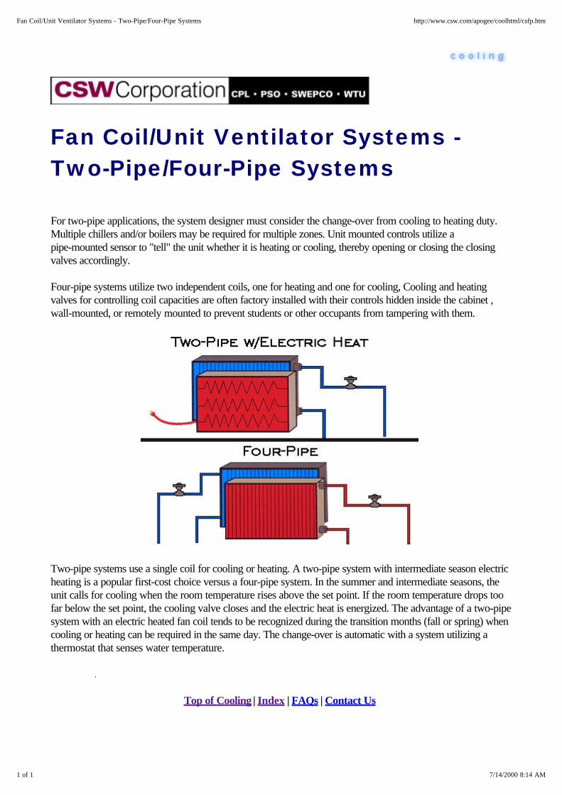
Fan Coil/Unit Ventilator Systems -Two-Pipe/Four-Pipe Systems
For two-pipe applications, the system designer must consider the change-over from cooling to heating duty.Multiple chillers and/or boilers may be required for multiple zones. Unit mounted controls utilize apipe-mounted sensor to "tell" the unit whether it is heating or cooling, thereby opening or closing the closingvalves accordingly.
Four-pipe systems utilize two independent coils, one for heating and one for cooling, Cooling and heatingvalves for controlling coil capacities are often factory installed with their controls hidden inside the cabinet ,wall-mounted, or remotely mounted to prevent students or other occupants from tampering with them.
Two-pipe systems use a single coil for cooling or heating. A two-pipe system with intermediate season electricheating is a popular first-cost choice versus a four-pipe system. In the summer and intermediate seasons, theunit calls for cooling when the room temperature rises above the set point. If the room temperature drops toofar below the set point, the cooling valve closes and the electric heat is energized. The advantage of a two-pipesystem with an electric heated fan coil tends to be recognized during the transition months (fall or spring) whencooling or heating can be required in the same day. The change-over is automatic with a system utilizing athermostat that senses water temperature.
Top of Cooling | Index | FAQs | Contact Us
1 of 1 7/14/2000 8:14 AM
Fan Coil/Unit Ventilator Systems - Two-Pipe/Four-Pipe Systems http://www.csw.com/apogee/coolhtml/csfp.htm
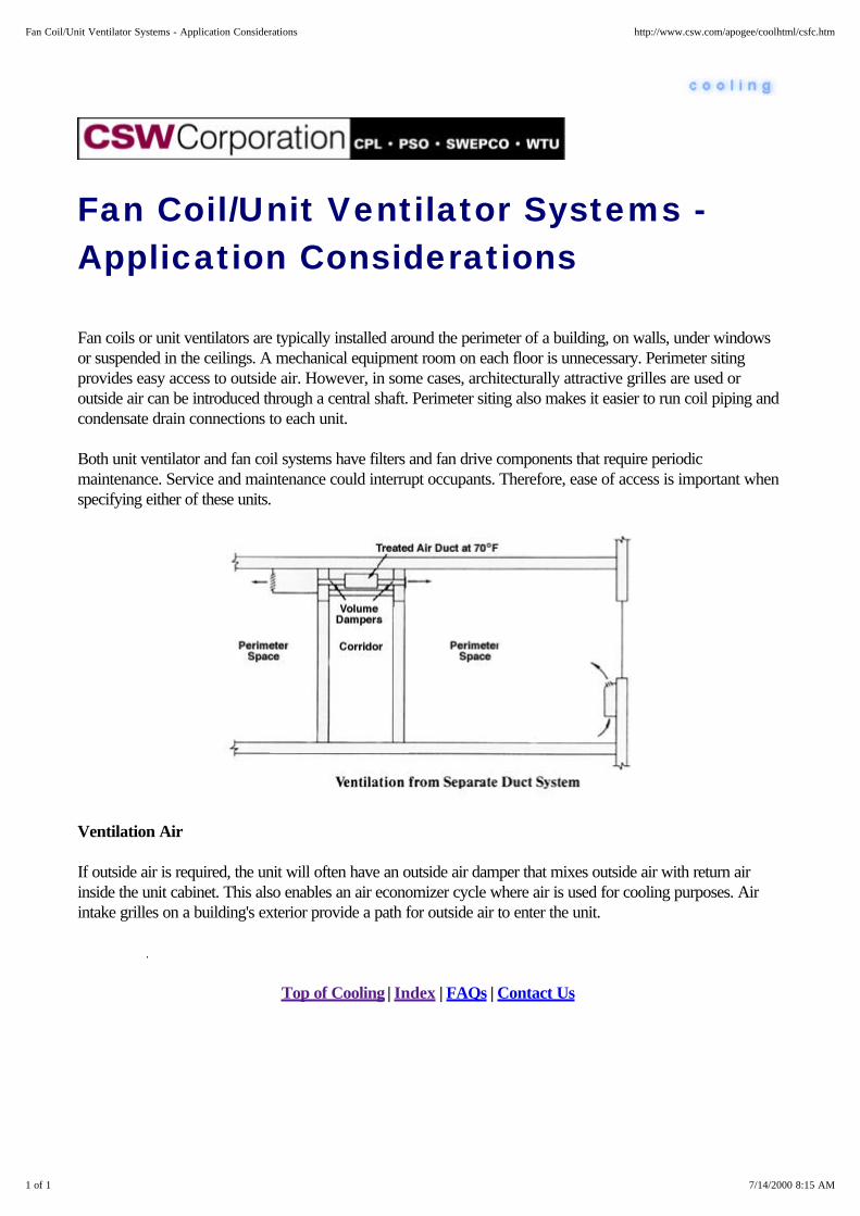
Fan Coil/Unit Ventilator Systems -Application Considerations
Fan coils or unit ventilators are typically installed around the perimeter of a building, on walls, under windowsor suspended in the ceilings. A mechanical equipment room on each floor is unnecessary. Perimeter sitingprovides easy access to outside air. However, in some cases, architecturally attractive grilles are used oroutside air can be introduced through a central shaft. Perimeter siting also makes it easier to run coil piping andcondensate drain connections to each unit.
Both unit ventilator and fan coil systems have filters and fan drive components that require periodicmaintenance. Service and maintenance could interrupt occupants. Therefore, ease of access is important whenspecifying either of these units.
Ventilation Air
If outside air is required, the unit will often have an outside air damper that mixes outside air with return airinside the unit cabinet. This also enables an air economizer cycle where air is used for cooling purposes. Airintake grilles on a building's exterior provide a path for outside air to enter the unit.
Top of Cooling | Index | FAQs | Contact Us
1 of 1 7/14/2000 8:15 AM
Fan Coil/Unit Ventilator Systems - Application Considerations http://www.csw.com/apogee/coolhtml/csfc.htm

Differences Between Unit Ventilatorand Fan Coil Systems
One main difference is in the unit cabinetry. Unit ventilatorstypically have heavier sheet metal cabinets which hold upbetter in the school environment. Classroom unit ventilatorsalso have architectural advantages. School room units canhave shelving or cabinetry built alongside the unit to help hidethe comfort source.
Another difference is that unit ventilators are usually designedto deliver large amounts of outside air through exterior wallopenings. Indoor air quality has become a major issue,especially in schools. ASHRAE Standards recommend everlarger percentages of outside air per student (i.e. 15 cfm perstudent). This results in larger ventilation loads. A classroomunit ventilator is specifically designed to handle these loads.In addition, utilizing chilled water and hot water coils allowsfor more stable control of coil discharge air temperature thanwith a direct expansion coil.
Heat gains can be as large as 7°F when a classroomsuddenly fills with students. By taking in the outside air, unitventilators can provide "free cooling" during cooler weather.A discharge air thermostat maintains a minimum leaving airtemperature from the unit to prevent "dumping" of cold aironto students seated near the unit.
Unit ventilators are generally available in larger sizes than fan coils, and both unit types often have their controlshidden inside the cabinet or remotely mounted to prevent students or other occupants from tampering withthem.
Top of Cooling | Index | FAQs | Contact Us
1 of 1 7/14/2000 8:15 AM
Differences Between Unit Ventilator and Fan Coil Systems http://www.csw.com/apogee/coolhtml/csfu.htm

2 of 2 7/14/2000 8:12 AM
Fan Coil/Unit Ventilator Systems - Description http://www.csw.com/apogee/coolhtml/csfd.htm

Top of Cooling | Index | FAQs | Contact Us
2 of 2 7/13/2000 11:21 PM
Fan Coil/Unit Ventilator Systems http://www.csw.com/apogee/coolhtml/cxsf.htm
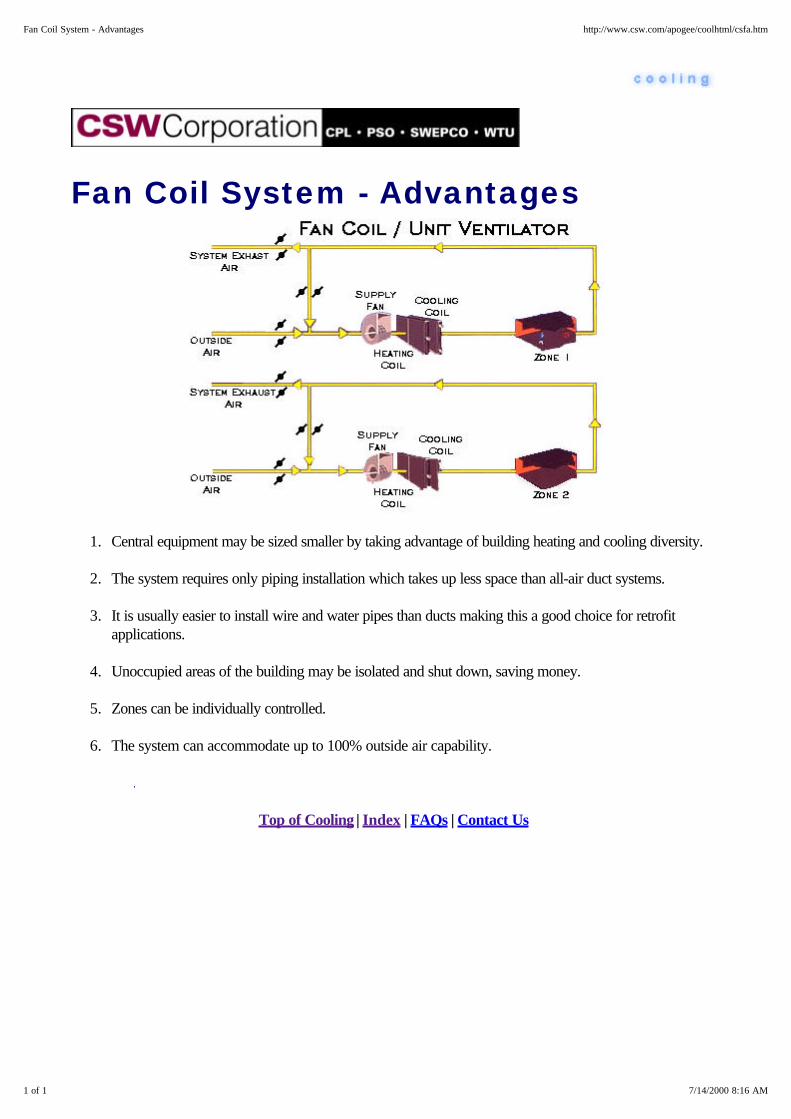
Fan Coil System - Advantages
1. Central equipment may be sized smaller by taking advantage of building heating and cooling diversity.
2. The system requires only piping installation which takes up less space than all-air duct systems.
3. It is usually easier to install wire and water pipes than ducts making this a good choice for retrofitapplications.
4. Unoccupied areas of the building may be isolated and shut down, saving money.
5. Zones can be individually controlled.
6. The system can accommodate up to 100% outside air capability.
Top of Cooling | Index | FAQs | Contact Us
1 of 1 7/14/2000 8:16 AM
Fan Coil System - Advantages http://www.csw.com/apogee/coolhtml/csfa.htm

Fan Coil System - Disadvantages
1. The Fan Coil System requires more maintenance than "all air" systems, and the maintenance work (suchas servicing filters) is performed in occupied areas.
2. Condensate must be disposed of at each unit.
3. Interior zones may require separate ducts to deliver outside (ventilation) air.
Top of Cooling | Index | FAQs | Contact Us
1 of 1 7/14/2000 8:16 AM
Fan Coil System - Disadvantages http://www.csw.com/apogee/coolhtml/csfv.htm

Unit Ventilator System Advantages
1. Central equipment may be sized smaller by taking advantage of building heating and cooling diversity.
2. The system requires only piping installation which takes up less space than duct systems.
3. It is usually easier to install wire and water pipes than ducts, making this a good choice for retrofitapplications.
4. Unoccupied areas of the building may be isolated and shut down, saving money.
5. Zones can be individually controlled.
6. Institutional grade units can withstand significant occupant abuse.
7. The system can accommodate up to 100% outside air capability.
Unit ventilators have the added advantages of: Heavier cabinetry to withstand rigors of the classroom Added insulation for quieter operation Numerous control options Optional complementary bookshelves and cabinets that add valuable storage space.
Top of Cooling | Index | FAQs | Contact Us
1 of 1 7/14/2000 8:16 AM
Unit Ventilator System Advantages http://www.csw.com/apogee/coolhtml/csfe.htm

Unit Ventilator SystemDisadvantages
1. The fan coil system requires more maintenance than "all air" systems, and the maintenance work (suchas servicing filters) is performed in occupied areas.
2. Condensate must be disposed of at each unit.
3. Interior zones may require separate ducts to deliver outside air.
4. Large exterior wall openings are required at each unit to accommodate 100% outside air capability.
Top of Cooling | Index | FAQs | Contact Us
1 of 1 7/14/2000 8:17 AM
Unit Ventilator System Disadvantages http://www.csw.com/apogee/coolhtml/csff.htm
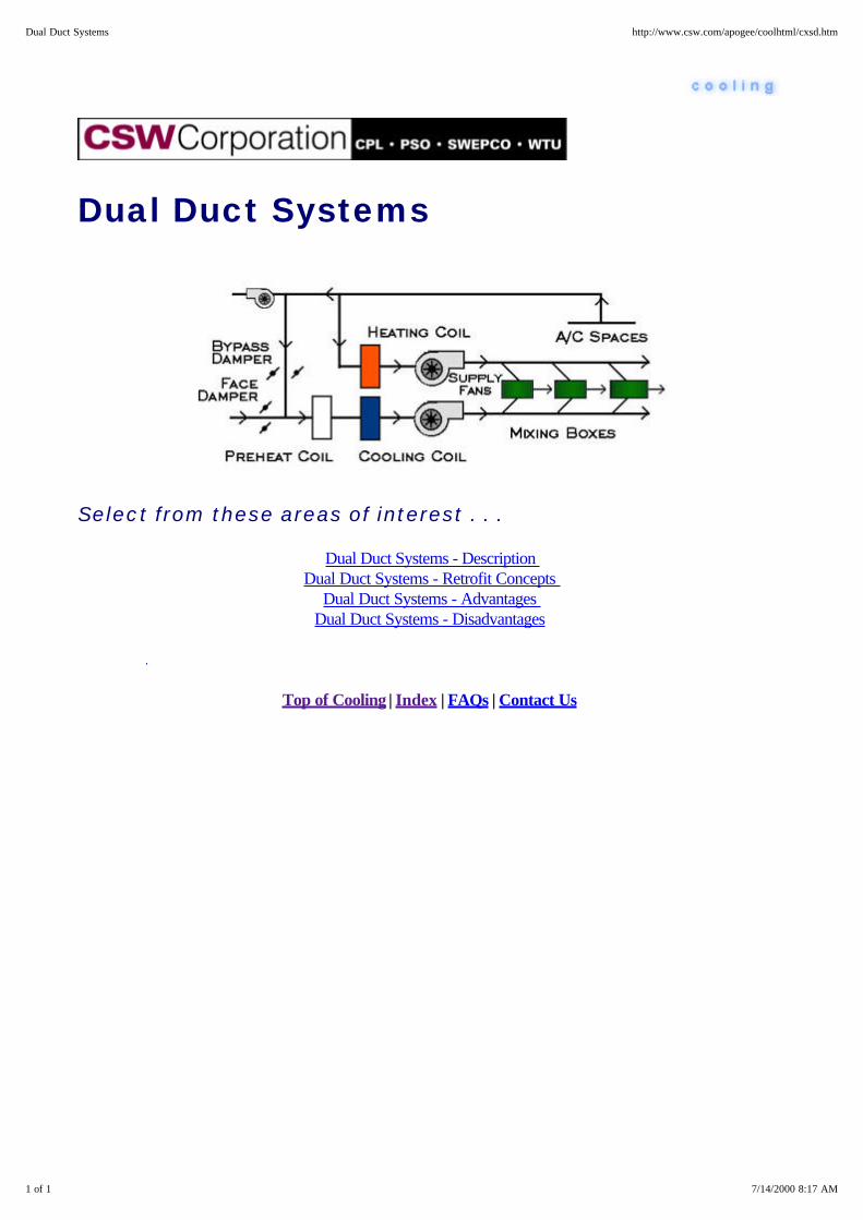
Dual Duct Systems
Select from these areas of interest . . .
Dual Duct Systems - Description Dual Duct Systems - Retrofit Concepts
Dual Duct Systems - Advantages Dual Duct Systems - Disadvantages
Top of Cooling | Index | FAQs | Contact Us
1 of 1 7/14/2000 8:17 AM
Dual Duct Systems http://www.csw.com/apogee/coolhtml/cxsd.htm

Dual Duct Systems - Description
The dual duct system was popular in the early days of air conditioning. It had several advantages, but thedisadvantages, like excessive energy consumption, led to its downfall after the energy crisis of 1973.
The dual duct concept was fairly simple. A fan discharged air in a blow-thru arrangement that could either bedirected through the cooling coil or the heating coil. What determined which path the air would take? Actuallyit was a device separate from either the fan or the coil, a device called the dual duct mixing box. Understandinghow this box worked is the key to understanding how this system functioned.
The dual duct mixing box was just that: a mixing box. It had a damper, controlled by the zone's thermostat, thatmixed the correct amount of cool air and hot air to maintain the proper supply air temperature called for by thezone. This system worked on the same principal as your shower at home. Turn on a given volume and simplyadd more or less hot and cold water to achieve the proper water temperature. Replace the water with air andthe concept still holds true.
1 of 2 7/14/2000 8:19 AM
Dual Duct Systems - Description http://www.csw.com/apogee/coolhtml/csdd.htm
Dual Duct Systems - RetrofitConcepts
Provide a discriminator-type control so the cold deck is only supplying cold enough air for the most coolingdemanding zone and the hot deck is only supplying warm enough air for the most heat demanding zone. If a fulldiscriminator control cannot be utilized, designers might consider the use of reset.
Potentially add heat recovery to the chillers for "free" heat for the hot deck. Consider turning this system into adual duct/VAV system by replacing the dual duct mixing boxes with dual duct VAV boxes, adding an airmodulation method to the fan, and adding the appropriate diffusers.
Top of Cooling | Index | FAQs | Contact Us
1 of 1 7/14/2000 8:18 AM
Dual Duct Systems - Retrofit Concepts http://www.csw.com/apogee/coolhtml/csdr.htm

Dual Duct Systems - Advantages
This system, like most "mixing" systems, had some major advantages for the time: it did not require themodulation of the fan, it was fairly simple and, as with all mixing systems, it had excellent dehumidificationcapabilities. However, dual duct was more complex than terminal reheat. A common problem was that themixing boxes that were supposed to be constant volume weren't, which resulted in air shortages and excessmixing in certain areas.
Top of Cooling | Index | FAQs | Contact Us
1 of 1 7/14/2000 8:19 AM
Dual Duct Systems - Advantages http://www.csw.com/apogee/coolhtml/csda.htm
Dual Duct Systems - Disadvantages
This system had several flaws which caused it to become essentially obsolete by the late 1970's. The primaryflaw was high energy consumption. The fact that the system had to mix hot and cool air to simply maintainspace temperature meant that it consumed large amounts of energy.
The second flaw was its lack of flexibility. Ironically, this system, theoretically, had the potential for moreflexibility than either of the other two popular systems of the time: terminal reheat or multizone. By simplyadding an additional dual duct box, a zone could be added. However, this typically was not done because itfrequently caused air balancing problems throughout the rest of the system.
Finally, this system had another serious problem: high first cost. This was especially critical when faced with thenew cost-competitive VAV systems being introduced in the early 1970's.
Top of Cooling | Index | FAQs | Contact Us
1 of 1 7/14/2000 8:19 AM
Dual Duct Systems - Disadvantages http://www.csw.com/apogee/coolhtml/csdv.htm

Cooling System Design Objectives
Cooling system problems often emanate from the differences between three perspectives: The phrases: "asdrawn," "as built," and "as operated," indicate these differing viewpoints representing the system designer, thebuilder or installer, and the system operator.
"As drawn" highlights the designer's perspective. Here, the emphasis is often on designing the building to agiven budget. Typically amenities and other perceived "moneymaking" equipment have budget priority over the"money-using" HVAC equipment. Even so, the design community will often specify relatively sophisticatedHVAC systems. However, the designer's assumption is that the building owner is familiar with the HVACdesign and will implement the system as designed. And, in all too many cases, the designer is forced to specifythe HVAC system without regard for life-cycle costs.
Then the building owner exerts pressure, and as budgets are cut or shifted and the originally-specifiedequipment is delayed, finishing the building takes on a higher value. The worst case is "warehouse" engineeringwhere the contractor will substitute whatever is available in the warehouse for the original design.Unfortunately, these compromises and changes are seldom documented and often fail to even work up to theircapability as the contractor tinkers with system settings to avoid callbacks. For example, it is much easier toset supply air temperatures low and use reheat to correct unbalanced zones. (It's also much more costly to thebuilding owner).
The operator now enters the picture. They will often aggravate the situation and compound the problembecause no one ever trained them in efficient building operation. In fact, they're seldom rewarded for thecost-savings impact they can have associated with efficient building operation. The result is predictable: theyrespond first to "hot calls" and "cold calls" and learn to set controls or even bypass intrinsic energy efficiencyfeatures to avoid even getting these calls in the first place. The result is a predictable and steady degradation insystem performance.
Utilities, often with a little encouragement from their regulatory agencies, realize HVAC design and operationare important elements in building energy use. Utilities realize design and operation can significantly impactenergy efficiency and demand side management programs. Unfortunately, building owners or developersseldom share this viewpoint. Therefore, when a utility is able to assume at least an advisory role in buildingdesign and system operation through the design phase and various retrofit programs, they can promote energyefficiency and help assure a positive outcome.
Top of Cooling | Index | FAQs | Contact Us
1 of 1 7/14/2000 8:20 AM
Cooling System Design Objectives http://www.csw.com/apogee/coolhtml/cxso.htm
Packaged Terminal Air ConditioningUnits (PTAC)
Packaged Terminal Air Conditioning Units (PTAC) - Description
Packaged Terminal Air Conditioning Units (PTAC) - Advantages
Packaged Terminal Air Conditioning Units (PTAC) - Disadvantages
Top of Cooling | Index | FAQs | Contact Us
1 of 1 7/14/2000 8:21 AM
Packaged Terminal Air Conditioning Units (PTAC) http://www.csw.com/apogee/coolhtml/cxst.htm

Packaged Terminal Air ConditioningUnits (PTAC) - Description
Packaged terminal air conditioning units,PTACs, are typically selected where individualzones have an outside wall and are conditionedseparately with individual occupant control.PTACs are well suited to hotels, motels, nursinghomes and apartments. As the name implies, asingle package contains all the components ofan air-cooled refrigeration and air-handlingsystem in an individual package.
Units are designed for through-the-wallinstallation, with decorative outdoor grilles as anoption. Units are also available with variousheating options-electric resistance or hydronic.Other variations include the Packaged TerminalHeat Pump (PTHP).
Control configuration options include:
Unit or remote wall-mounted thermostat Provision for starting and stopping from acentral point Start and stop at preset times (for use less than 24 hours) Individual over-ride Multiple units controlled from one thermostat
Top of Cooling | Index | FAQs | Contact Us
1 of 1 7/14/2000 8:22 AM
Packaged Terminal Air Conditioning Units (PTAC) - Description http://www.csw.com/apogee/coolhtml/cstd.htm
Packaged Terminal Air ConditioningUnits (PTAC) - Advantages
1. The initial cost is typically less than a central system adapted for room occupant control.
2. Building space is conserved since ductwork and mechanical rooms are not needed.
3. Installation is easy. It's almost a matter of wiring the unit in a hole in the wall.
4. Old or malfunctioning units may be quickly and easily replaced with a spare chassis.
5. Numerous control options.
6. Well-suited to spaces requiring many individual temperature control zones.
Top of Cooling | Index | FAQs | Contact Us
1 of 1 7/14/2000 8:22 AM
Packaged Terminal Air Conditioning Units (PTAC) - Advantages http://www.csw.com/apogee/coolhtml/csta.htm

Packaged Terminal Air ConditioningUnits (PTAC) - Disadvantages
1. The system tends to have higher maintenance costs because of multiple compressors and fans.
2. Routine service in the occupied space required to change filters and clean coils.
3. The system is only applicable to perimeter zones.
4. Noise levels vary considerably and the system is generally too loud for critical applications.
5. PTAC's are not as energy efficient as central systems.
6. Humidification, when required, must be supplied by a separate system.
7. Life expectancy, with proper maintenance, projected at 10 to 15 years.
8. Temperature control typically cause swings in room temperature.
Top of Cooling | Index | FAQs | Contact Us
1 of 1 7/14/2000 8:22 AM
Packaged Terminal Air Conditioning Units (PTAC) - Disadvantages http://www.csw.com/apogee/coolhtml/cstv.htm

Water Source Heat Pumps
Water Source Heat Pumps - Description
Water Source Heat Pumps - Application Considerations
Water Source Heat Pumps - Advantages
Water Source Heat Pumps - Disadvantages
Top of Cooling | Index | FAQs | Contact Us
1 of 1 7/14/2000 8:23 AM
Water Source Heat Pumps http://www.csw.com/apogee/coolhtml/cxsw.htm
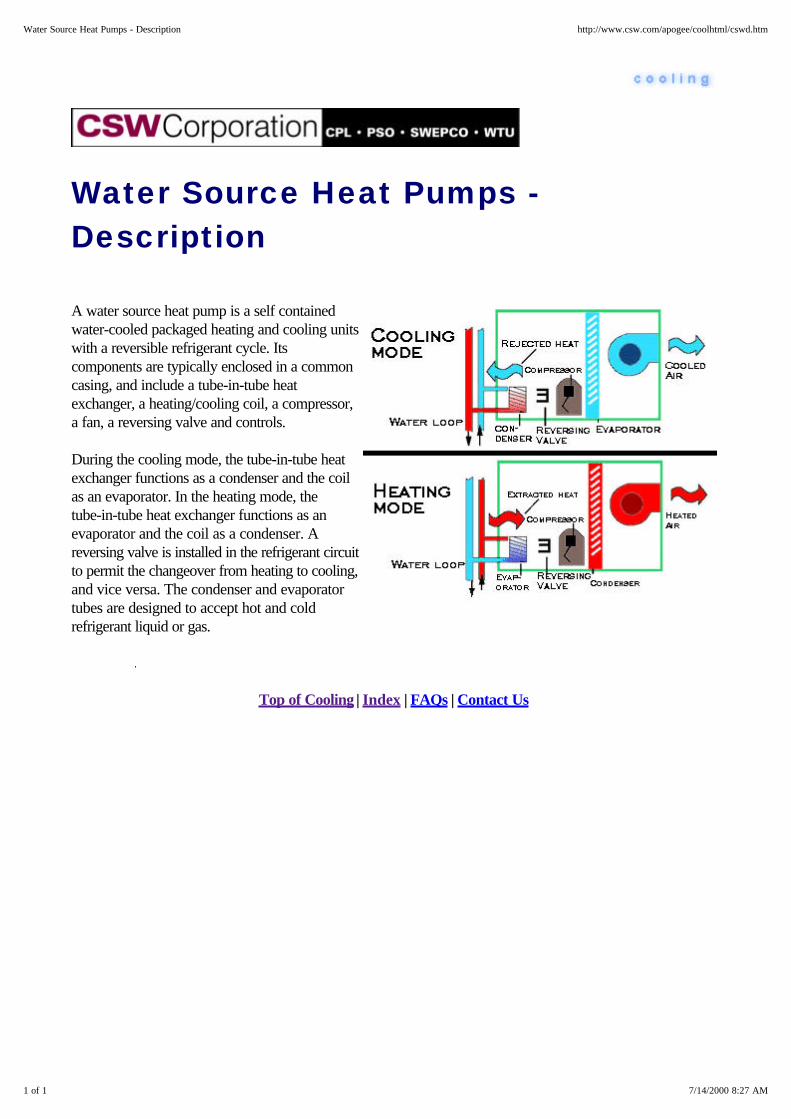
Water Source Heat Pumps -Description
A water source heat pump is a self containedwater-cooled packaged heating and cooling unitswith a reversible refrigerant cycle. Itscomponents are typically enclosed in a commoncasing, and include a tube-in-tube heatexchanger, a heating/cooling coil, a compressor,a fan, a reversing valve and controls.
During the cooling mode, the tube-in-tube heatexchanger functions as a condenser and the coilas an evaporator. In the heating mode, thetube-in-tube heat exchanger functions as anevaporator and the coil as a condenser. Areversing valve is installed in the refrigerant circuitto permit the changeover from heating to cooling,and vice versa. The condenser and evaporatortubes are designed to accept hot and coldrefrigerant liquid or gas.
Top of Cooling | Index | FAQs | Contact Us
1 of 1 7/14/2000 8:27 AM
Water Source Heat Pumps - Description http://www.csw.com/apogee/coolhtml/cswd.htm
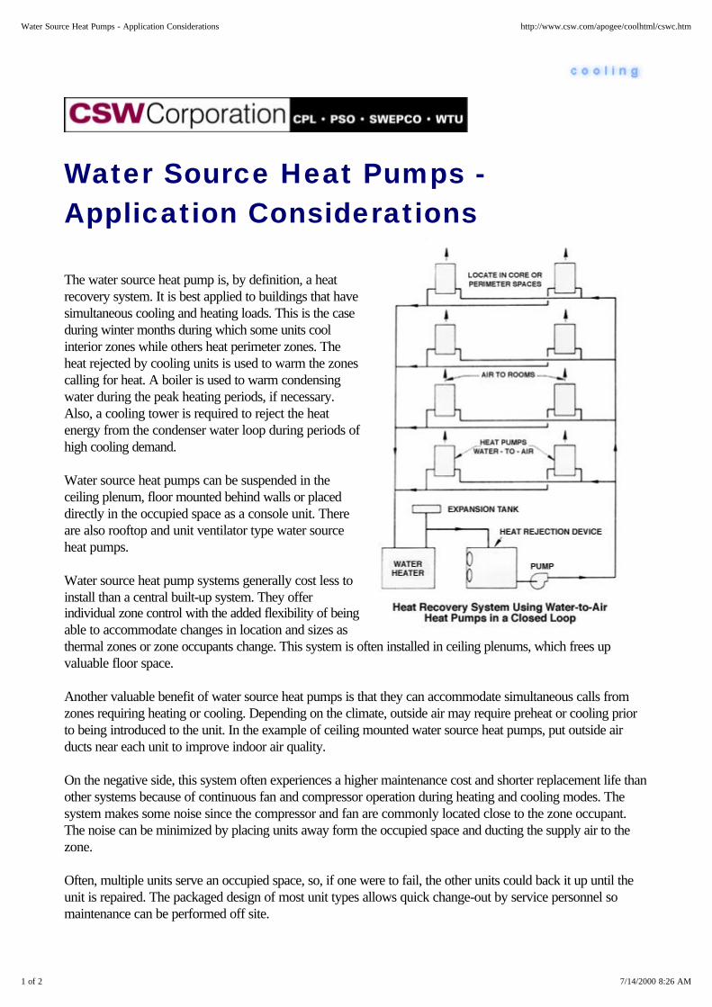
Water Source Heat Pumps -Application Considerations
The water source heat pump is, by definition, a heatrecovery system. It is best applied to buildings that havesimultaneous cooling and heating loads. This is the caseduring winter months during which some units coolinterior zones while others heat perimeter zones. Theheat rejected by cooling units is used to warm the zonescalling for heat. A boiler is used to warm condensingwater during the peak heating periods, if necessary.Also, a cooling tower is required to reject the heatenergy from the condenser water loop during periods ofhigh cooling demand.
Water source heat pumps can be suspended in theceiling plenum, floor mounted behind walls or placeddirectly in the occupied space as a console unit. Thereare also rooftop and unit ventilator type water sourceheat pumps.
Water source heat pump systems generally cost less toinstall than a central built-up system. They offerindividual zone control with the added flexibility of beingable to accommodate changes in location and sizes asthermal zones or zone occupants change. This system is often installed in ceiling plenums, which frees upvaluable floor space.
Another valuable benefit of water source heat pumps is that they can accommodate simultaneous calls fromzones requiring heating or cooling. Depending on the climate, outside air may require preheat or cooling priorto being introduced to the unit. In the example of ceiling mounted water source heat pumps, put outside airducts near each unit to improve indoor air quality.
On the negative side, this system often experiences a higher maintenance cost and shorter replacement life thanother systems because of continuous fan and compressor operation during heating and cooling modes. Thesystem makes some noise since the compressor and fan are commonly located close to the zone occupant.The noise can be minimized by placing units away form the occupied space and ducting the supply air to thezone.
Often, multiple units serve an occupied space, so, if one were to fail, the other units could back it up until theunit is repaired. The packaged design of most unit types allows quick change-out by service personnel somaintenance can be performed off site.
1 of 2 7/14/2000 8:26 AM
Water Source Heat Pumps - Application Considerations http://www.csw.com/apogee/coolhtml/cswc.htm

Water Source Heat Pumps -Advantages
1. Water Source Heat Pumps can save money and lower energy consumption by: a. recovering heat from building interior zones and "pumping" it to the perimeter of the building. b. isolating and shutting down unoccupied areas of the building.
2. Heat pump units are installed inside the building; they aren't exposed to the weather. This is especiallyimportant, for example, in coastal areas were the atmosphere can be very corrosive.
3. It's very flexible. The system can be subdivided or expanded into new zones to fit building remodelingor additions easily and inexpensively.
4. This system is well-suited to "tenant finish" installations.
5. While the loop piping is installed throughout the building, the heat pumps can be installed as tenantspace is scheduled for occupancy.
Top of Cooling | Index | FAQs | Contact Us
1 of 1 7/14/2000 8:26 AM
Water Source Heat Pumps - Advantages http://www.csw.com/apogee/coolhtml/cswa.htm
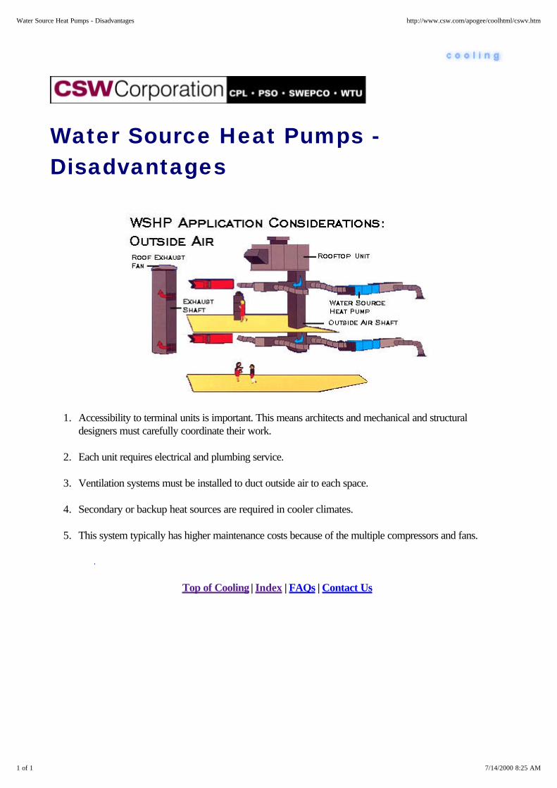
Water Source Heat Pumps -Disadvantages
1. Accessibility to terminal units is important. This means architects and mechanical and structuraldesigners must carefully coordinate their work.
2. Each unit requires electrical and plumbing service.
3. Ventilation systems must be installed to duct outside air to each space.
4. Secondary or backup heat sources are required in cooler climates.
5. This system typically has higher maintenance costs because of the multiple compressors and fans.
Top of Cooling | Index | FAQs | Contact Us
1 of 1 7/14/2000 8:25 AM
Water Source Heat Pumps - Disadvantages http://www.csw.com/apogee/coolhtml/cswv.htm
VAV Systems
VAV Systems - Description
VAV Systems - Application Considerations
Changeover/Bypass VAV Systems
Reheat VAV
Parallel Fan Powered VAV
Series VAV
Dual Duct VAV
Top of Cooling | Index | FAQs | Contact Us
1 of 1 7/14/2000 8:28 AM
VAV Systems http://www.csw.com/apogee/coolhtml/cxsv.htm

VAV Systems - Description
In the 1970's, the design community made serious efforts to reduce system energy costs and, at the same time,add independent zone control: It was during this period the variable air volume (VAV) systems gained theirpopularity. VAV systems are designed to supply only the volume of conditioned air to a space that is neededto satisfy the load. Fan energy is saved when the volume of air handled by the fan is reduced. Air volumecontrol is accomplished by installing modulating dampers, or in some cases, an air valve, in the supply duct toeach zone. As the room temperature demand becomes satisfied, the thermostat signals the damper to move thesupply air zone valve toward the closed position.
When zone valves are throttled, the static pressure in the supply duct changes. A static pressure sensor locatedin the supply duct senses the static pressure change, and either increases or decreases the airflow from thesource, using variable speed control or dampers on the main air supply fan.
A key component in the VAV system is the air valve. It is commonly installed inside an insulated sheet metalbox suspended in a ceiling plenum. The air valve has a damper that regulates the air flow in response to theroom's thermostat. A multi-port pressure sensing ring provides both accurate airflow sensing and control inresponse to duct static pressure.
As VAV systems have evolved, so have the terminals. There are six popular VAV systems. They are:
Shutoff VAV Reheat Parallel Fan Powered Series Fan Powered Dual Duct Changeover/Bypass
Top of Cooling | Index | FAQs | Contact Us
1 of 1 7/14/2000 8:31 AM
VAV Systems - Description http://www.csw.com/apogee/coolhtml/csvd.htm

VAV Systems - ApplicationConsiderations
There are many factors to consider when designing VAV systems. Here are a few:
1. VAV systems are popular because they can easily accommodate added control zones.
2. Small zones contribute to precise temperature control, which facilitates occupant comfort. However, thecosts increase with the number of zones.
3. Air distribution is another important consideration with VAV systems. The diffusers must deliver air atvarying velocities. A standard diffuser may work well for constant volume applications, but not so wellat part load air velocities. Improperly selected diffusers may even dump air at design air flows. Properdischarge geometry provided by the linear slot diffuser contributes to good air distribution.
4. Lack of air movement can lead to poor indoor air quality. The result is stuffiness and discomfort. Aminimum stop on the air valve or the use of series or parallel fan powered VAV boxes can help preventthe valve from closing off completely, and closing off airflow to the zone. One method of increasing zoneairflow during light cooling loads is to design an intelligent control scheme that resets the leaving airtemperature off the coil upward. This method will circulate more air at higher temperatures, and willsave energy.
5. Building pressure control is especially important in VAV systems. In a building with an outside aireconomizer damper, the volume of outside air introduced varies with the building cooling load andoutdoor temperature. The building is typically balanced at the minimum outside air setting. When theoutside air damper opens to provide economizer cooling, more air is entering the building than is beingexhausted. As a result, the building pressure rises. A popular scheme used to solve this problemcompares space pressure with the outdoor air reference pressure. The exhaust fan is modulated, asnecessary, to maintain a fixed, slightly positive space pressure.
Top of Cooling | Index | FAQs | Contact Us
1 of 1 7/14/2000 8:31 AM
VAV Systems - Application Considerations http://www.csw.com/apogee/coolhtml/csva.htm

Changeover/Bypass VAV Systems
Changeover/Bypass VAV Systems - Description
Changeover/Bypass VAV Systems - Application Considerations
Top of Cooling | Index | FAQs | Contact Us
1 of 1 7/14/2000 8:32 AM
Changeover/Bypass VAV Systems http://www.csw.com/apogee/coolhtml/cxsvc.htm
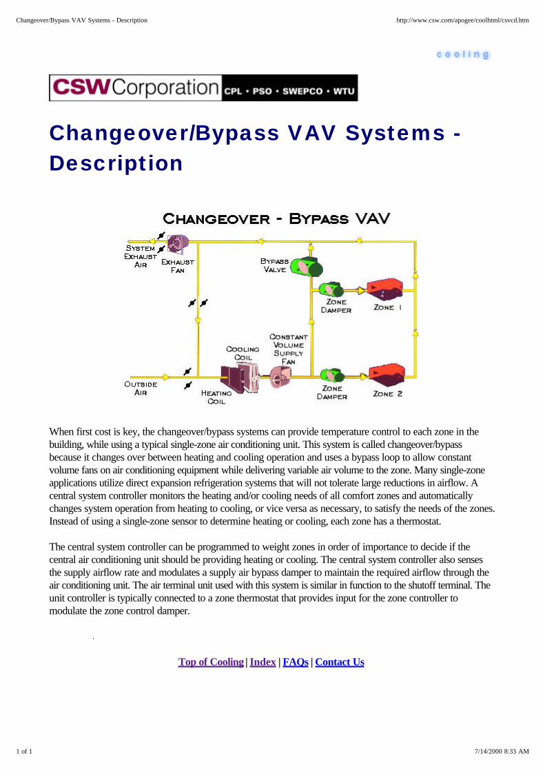
Changeover/Bypass VAV Systems -Description
When first cost is key, the changeover/bypass systems can provide temperature control to each zone in thebuilding, while using a typical single-zone air conditioning unit. This system is called changeover/bypassbecause it changes over between heating and cooling operation and uses a bypass loop to allow constantvolume fans on air conditioning equipment while delivering variable air volume to the zone. Many single-zoneapplications utilize direct expansion refrigeration systems that will not tolerate large reductions in airflow. Acentral system controller monitors the heating and/or cooling needs of all comfort zones and automaticallychanges system operation from heating to cooling, or vice versa as necessary, to satisfy the needs of the zones.Instead of using a single-zone sensor to determine heating or cooling, each zone has a thermostat.
The central system controller can be programmed to weight zones in order of importance to decide if thecentral air conditioning unit should be providing heating or cooling. The central system controller also sensesthe supply airflow rate and modulates a supply air bypass damper to maintain the required airflow through theair conditioning unit. The air terminal unit used with this system is similar in function to the shutoff terminal. Theunit controller is typically connected to a zone thermostat that provides input for the zone controller tomodulate the zone control damper.
Top of Cooling | Index | FAQs | Contact Us
1 of 1 7/14/2000 8:33 AM
Changeover/Bypass VAV Systems - Description http://www.csw.com/apogee/coolhtml/csvcd.htm

Changeover/Bypass VAV Systems -Application Considerations
A changeover/bypass VAV system has many of the same application guidelines as the more traditional VAVsystems. However, there is one additional consideration, thermal zoning. A changeover/bypass VAV systemcannot accommodate simultaneous cooling and heating demands on the same unit, For applications requiringheat on demand when the air conditioning unit is in the cooling mode, duct heating coils can be installed andcontrolled from the zone damper controller and zone thermostat.
This does not limit this system to small buildings. Larger office buildings, schools, and manufacturing facilitiescan be served as long as the building can be thermally zones to accommodate the systems capabilities, i.e.zones should have similar thermal loading characteristics. Each thermal zone is then assigned a heating andcooling unit which serves a number of individua1 changeover/bypass VAV terminals.
Top of Cooling | Index | FAQs | Contact Us
1 of 1 7/14/2000 8:32 AM
Changeover/Bypass VAV Systems - Application Considerations http://www.csw.com/apogee/coolhtml/csvca.htm

Reheat VAV
Reheat VAV - Description
Reheat VAV - Advantages
Reheat VAV - Disadvantages
Top of Cooling | Index | FAQs | Contact Us
1 of 1 7/14/2000 8:34 AM
Reheat VAV http://www.csw.com/apogee/coolhtml/cxsvr.htm
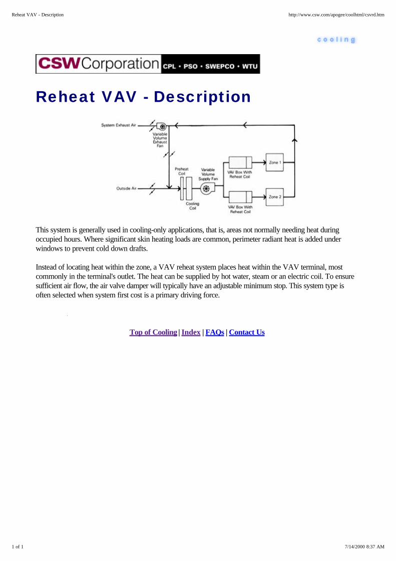
Reheat VAV - Description
This system is generally used in cooling-only applications, that is, areas not normally needing heat duringoccupied hours. Where significant skin heating loads are common, perimeter radiant heat is added underwindows to prevent cold down drafts.
Instead of locating heat within the zone, a VAV reheat system places heat within the VAV terminal, mostcommonly in the terminal's outlet. The heat can be supplied by hot water, steam or an electric coil. To ensuresufficient air flow, the air valve damper will typically have an adjustable minimum stop. This system type isoften selected when system first cost is a primary driving force.
Top of Cooling | Index | FAQs | Contact Us
1 of 1 7/14/2000 8:37 AM
Reheat VAV - Description http://www.csw.com/apogee/coolhtml/csvrd.htm

Reheat VAV - Advantages
1. The major equipment is centrally located. This permits operation and maintenance to take place outsideof occupied areas.
2. Temperature control for even a large number of zones is relatively inexpensive. Plus, this system canaccommodate simultaneous heating and cooling. Heating and cooling coils won't be fighting each other.
3. It's very flexible. The system can be subdivided or expanded into new zones to fit building remodelingor additions easily and inexpensively.
4. This system can save money by:
Modulating the fans. Fans consume a significant portion of the energy in the building, and VAVsystem fans run at substantially lower volumes most of the time. This offers the potential forsignificant energy savings.
Taking advantage of a building's heating and cooling diversity. This can lower the system's firstcost, as well as reduce energy consumption because it is using smaller equipment at more efficientpart-load conditions.
And, isolating and shutting down unoccupied areas of the building.
5. Since the system will most often operate below the design condition, noise levels will usually be lowerthan specifications.
6. VAV boxes with high minimum stops may be ideal for areas where constant airflow anddehumidification are required.
Top of Cooling | Index | FAQs | Contact Us
1 of 1 7/14/2000 8:35 AM
Reheat VAV - Advantages http://www.csw.com/apogee/coolhtml/csvpa.htm

Reheat VAV - Disadvantages
1. Accessibility to terminal units is important. This means architects and mechanical and structuraldesigners must carefully coordinate their work.
2. Each terminal unit has an air valve which requires either electrical or pneumatic service.
3. Each terminal unit has a heating coil which requires utility service and maintenance.
4. The system requires diffusers that can provide adequate distribution characteristics over a wide range ofair flows.
5. During the heating mode, the primary airflow is first cooled and then reheated resulting in increasedenergy consumption.
Top of Cooling | Index | FAQs | Contact Us
1 of 1 7/14/2000 8:36 AM
Reheat VAV - Disadvantages http://www.csw.com/apogee/coolhtml/csvrv.htm

Parallel Fan Powered VAV
Parallel Fan Powered VAV - Description
Parallel Fan Powered VAV - Advantages
Parallel Fan Powered VAV - Disadvantages
Top of Cooling | Index | FAQs | Contact Us
1 of 1 7/14/2000 8:38 AM
Parallel Fan Powered VAV http://www.csw.com/apogee/coolhtml/cxsvp.htm
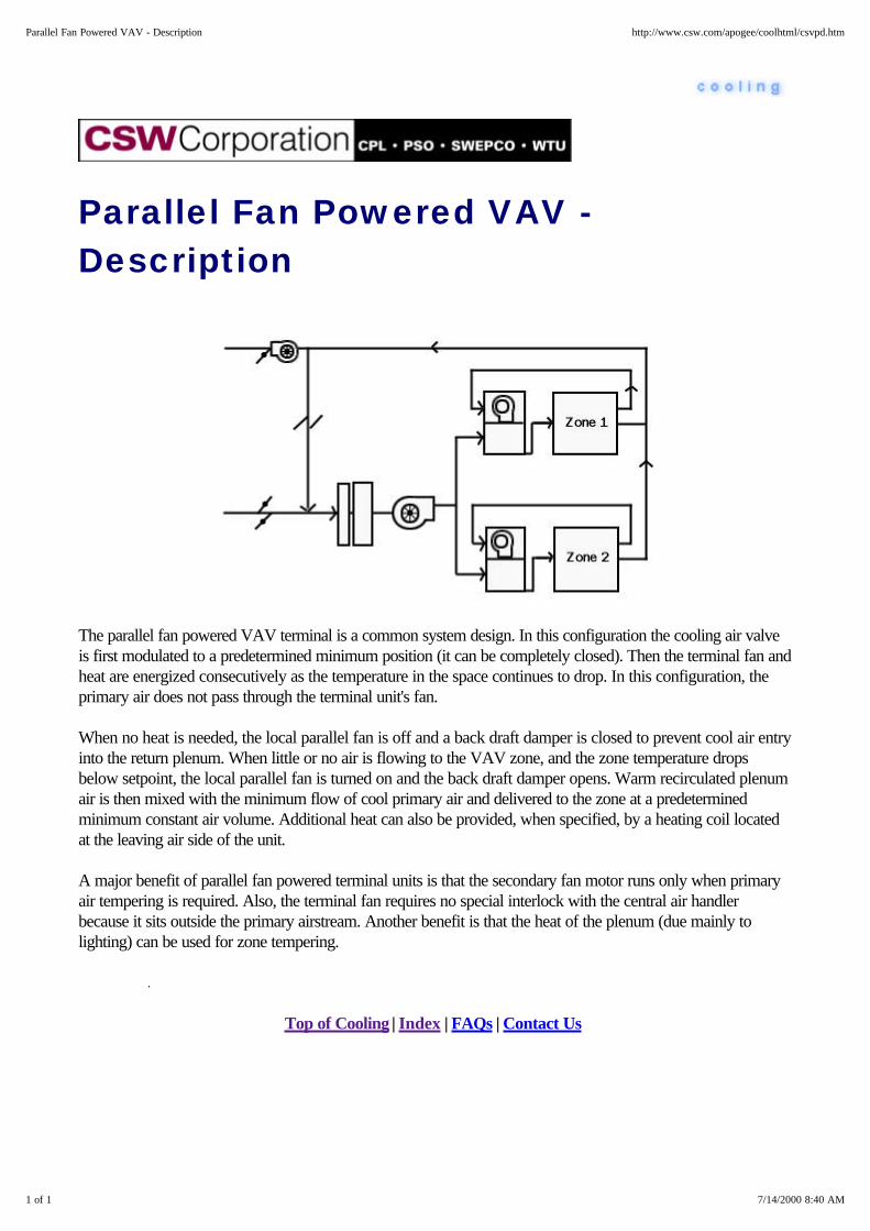
Parallel Fan Powered VAV -Description
The parallel fan powered VAV terminal is a common system design. In this configuration the cooling air valveis first modulated to a predetermined minimum position (it can be completely closed). Then the terminal fan andheat are energized consecutively as the temperature in the space continues to drop. In this configuration, theprimary air does not pass through the terminal unit's fan.
When no heat is needed, the local parallel fan is off and a back draft damper is closed to prevent cool air entryinto the return plenum. When little or no air is flowing to the VAV zone, and the zone temperature dropsbelow setpoint, the local parallel fan is turned on and the back draft damper opens. Warm recirculated plenumair is then mixed with the minimum flow of cool primary air and delivered to the zone at a predeterminedminimum constant air volume. Additional heat can also be provided, when specified, by a heating coil locatedat the leaving air side of the unit.
A major benefit of parallel fan powered terminal units is that the secondary fan motor runs only when primaryair tempering is required. Also, the terminal fan requires no special interlock with the central air handlerbecause it sits outside the primary airstream. Another benefit is that the heat of the plenum (due mainly tolighting) can be used for zone tempering.
Top of Cooling | Index | FAQs | Contact Us
1 of 1 7/14/2000 8:40 AM
Parallel Fan Powered VAV - Description http://www.csw.com/apogee/coolhtml/csvpd.htm
Parallel Fan Powered VAV -Advantages
1. The major equipment is centrally located. This permits operation and maintenance to take place outsideof occupied areas.
2. Temperature control for even a large number of zones is relatively inexpensive. Plus, this system canaccommodate simultaneous heating and cooling. Heating and cooling coils won't be fighting each other.
3. The fan powered VAV box can take advantage of the heating effect of lights to reduce building heatingrequirements.
4. It's very flexible. The system can be subdivided or expanded into new zones to fit building remodelingor additions easily and inexpensively.
5. This system can save money by:
Modulating the fans. Fans consume a significant portion of the energy in the building, and VAVsystem fans run at substantially lower volumes most of the time. This offers the potential forsignificant energy savings.
Taking advantage of a building's heating and cooling diversity. This can lower the system's firstcost, as well as reduce energy consumption because it is using smaller equipment at more efficientpart-load conditions.
And, isolating and shutting down unoccupied areas of the building.
6. Since the majority of the operation will be below design conditions, the noise level will often be lowerthan that specified at design.
Top of Cooling | Index | FAQs | Contact Us
1 of 1 7/14/2000 8:40 AM
Parallel Fan Powered VAV - Advantages http://www.csw.com/apogee/coolhtml/csvpadv.htm

Parallel Fan Powered VAV -Disadvantages
1. Accessibility to terminal units is important. This means architects and mechanical and structuraldesigners must carefully coordinate their work.
2. Each terminal unit has a fan and filter which require electric service as well as periodic maintenance.
3. Each terminal unit has an air valve which requires either electrical or pneumatic service.
4. The system requires diffusers that can provide adequate distribution characteristics over a wide range ofair flows.
Top of Cooling | Index | FAQs | Contact Us
1 of 1 7/14/2000 8:38 AM
Parallel Fan Powered VAV - Disadvantages http://www.csw.com/apogee/coolhtml/csvpv.htm

Series VAV
Select from these areas of interest . . .
Series VAV - Description Series VAV - Advantages
Series VAV - Disadvantages
Top of Cooling | Index | FAQs | Contact Us
1 of 1 7/14/2000 8:41 AM
Series VAV http://www.csw.com/apogee/coolhtml/cxsvs.htm

Series VAV - Description
Series fan powered terminal units are commonly used in VAV zones that not only require heat during occupiedhours, but also constant volume air delivery. With this system the terminal unit fan is in series with the centralfan. Therefore, primary air from the central fan always passes through the terminal unit fan. The local series fanis generally sized for 100 percent zone air flow since all primary airflow passes through it. This secondary fanoperates whenever there is a call for airflow to the zone. This ensures a constant flow of air, but thetemperature of the air varies.
As the zone is cooling requirement decreases, the valve's damper closes. As the damper closes, the air mixturesupplied to the zone contains less cool air and more warm recirculated plenum air. The heating coil located atthe leaving air side of the unit can provide additional heat.
Series fan powered terminals are often selected by designers who wish to take advantage of the uniquecharacteristics of constant air delivery to the zone, while still benefiting from the energy saving associated withVAV at the main air handler. Series terminal may be used throughout the entire building or they may beselectively applied in areas where constant airflow is desirable, such as washrooms, entrance ways, hallways,atriums, and conference rooms.
Series and parallel fan powered terminal units are also frequently used in low temperature air supply systems,since the unit fan can be sized so that warm recirculated plenum air is mixed with cool supply air. This raisesthe supply air temperature and minimizes potential for condensation on the diffuser. It also minimizes the coldair being dumped on occupants.
1 of 2 7/14/2000 8:43 AM
Series VAV - Description http://www.csw.com/apogee/coolhtml/csvsd.htm
Series VAV - Advantages
1. The major equipment is centrally located. This permits operation and maintenance to take place outsideof occupied areas.
2. Temperature control for even a large number of zones is relatively inexpensive. Plus, this system canaccommodate simultaneous heating and cooling. Heating and cooling coils won't be fighting each other.
3. The fan powered VAV box can take advantage of the heating effect of lights to reduce building heatingrequirements.
4. It's very flexible. The system can be subdivided or expanded into new zones to fit building remodelingor additions easily and inexpensively.
5. This system can save money by:
Modulating the fans. Fans consume a significant portion of the energy in the building, and VAVsystem fans run at substantially lower volumes most of the time. This offers the potential forsignificant energy savings.
Taking advantage of a building's heating and cooling diversity. This can lower the system's firstcost, as well as reduce energy consumption because it is using smaller equipment at more efficientpart-load conditions.
And, isolating and shutting down unoccupied areas of the building.
6. Since the majority of the operation will be below design conditions, the noise level will often be lowerthan that specified at design.
Top of Cooling | Index | FAQs | Contact Us
1 of 1 7/14/2000 8:42 AM
Series VAV - Advantages http://www.csw.com/apogee/coolhtml/csvsa.htm
Series VAV - Disadvantages
1. Accessibility to terminal units is important. This means architects and mechanical and structuraldesigners must carefully coordinate their work.
2. Each terminal unit has a fan and filter which require electric service as well as periodic maintenance.
3. Each terminal unit has an air valve which requires either electrical or pneumatic service.
Top of Cooling | Index | FAQs | Contact Us
1 of 1 7/14/2000 8:42 AM
Series VAV - Disadvantages http://www.csw.com/apogee/coolhtml/csvsv.htm
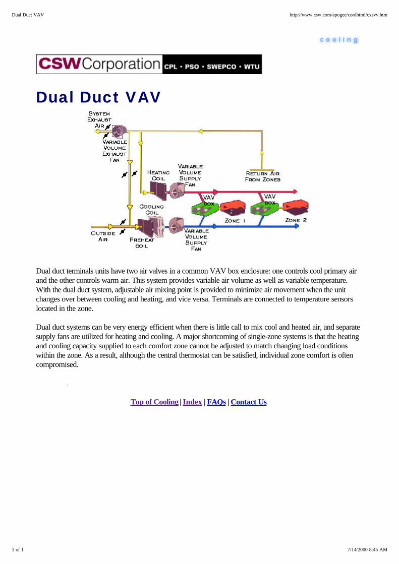
Dual Duct VAV
Dual duct terminals units have two air valves in a common VAV box enclosure: one controls cool primary airand the other controls warm air. This system provides variable air volume as well as variable temperature.With the dual duct system, adjustable air mixing point is provided to minimize air movement when the unitchanges over between cooling and heating, and vice versa. Terminals are connected to temperature sensorslocated in the zone.
Dual duct systems can be very energy efficient when there is little call to mix cool and heated air, and separatesupply fans are utilized for heating and cooling. A major shortcoming of single-zone systems is that the heatingand cooling capacity supplied to each comfort zone cannot be adjusted to match changing load conditionswithin the zone. As a result, although the central thermostat can be satisfied, individual zone comfort is oftencompromised.
Top of Cooling | Index | FAQs | Contact Us
1 of 1 7/14/2000 8:45 AM
Dual Duct VAV http://www.csw.com/apogee/coolhtml/cxsvv.htm
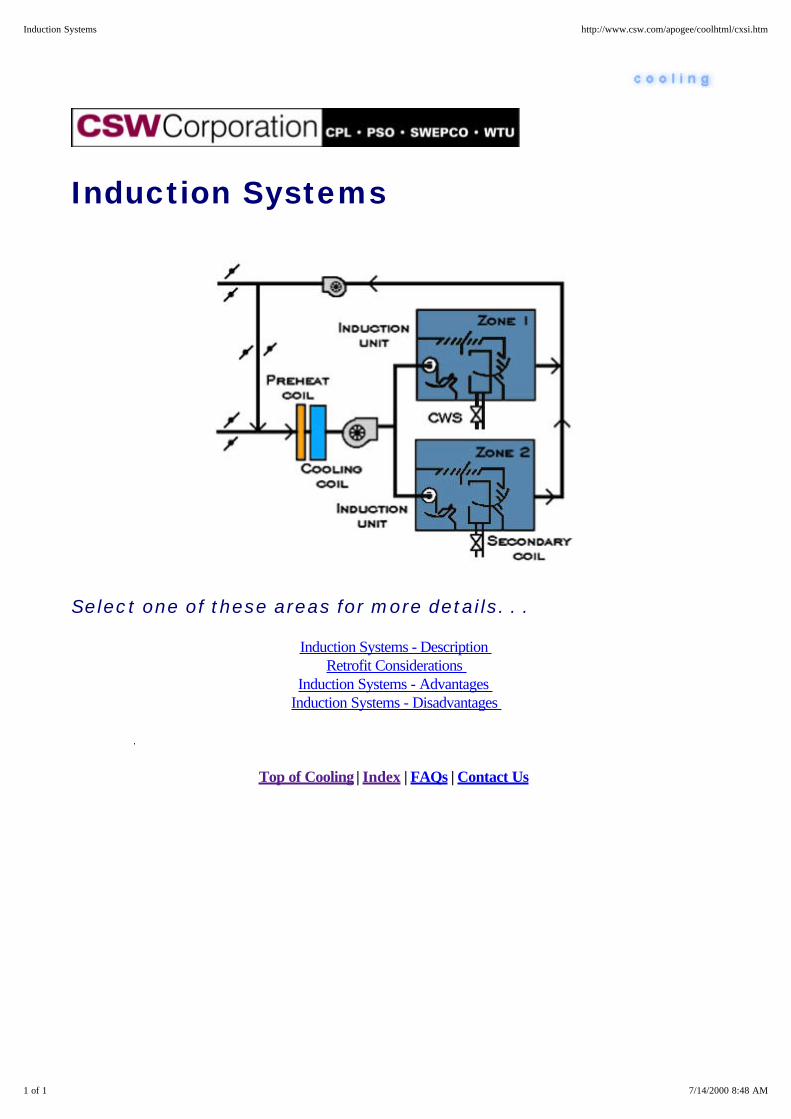
Induction Systems
Select one of these areas for more details. . .
Induction Systems - Description Retrofit Considerations
Induction Systems - Advantages Induction Systems - Disadvantages
Top of Cooling | Index | FAQs | Contact Us
1 of 1 7/14/2000 8:48 AM
Induction Systems http://www.csw.com/apogee/coolhtml/cxsi.htm

Induction Systems - Description
In the 1950's and 60's induction was a popular system in certain areas of the country, especially for buildingswith large skin loads like those with high glass content. In addition, it was ideal for applications where it wasdesirable not to have dehumidification take place in the occupied space, like hospital patient rooms.
Why high glass content buildings? Because the low air temperature of the primary air combined with thesecondary air could significantly reduce the quantity of air required compared to all-air systems. This wasespecially important because most of the buildings at the time used large quantities of glass which had poorshading coefficients and U factors which required large air quantities in all-air systems.
Why hospital patient rooms? Primarily because all of the dehumidification was done at the primary air unit andnot in the patient room itself. This eliminated in-room condensate drain pans where microorganisms couldcollect and breed, possibly spreading disease.
The concept involved using induction units to handle the perimeter sensible loads of the building and a separateconstant volume, or in some cases, a cooling-only VAV system to handle the interior load. The primary airwas typically 100 percent outside air and was supplied to the induction units through small, high velocity spiralductwork. High pressure was needed to force the air through the nozzles of the unit at an even higher velocitywhich in turn induced secondary air across the units' heating/cooling coil. The idea was to schedule the primaryair temperature based on outside air and allow the heating and cooling coil to trim the difference. This wasespecially complex in the case of two pipe induction systems where the change-over from heating to coolingwas critical.
Top of Cooling | Index | FAQs | Contact Us
1 of 1 7/14/2000 8:48 AM
Induction Systems - Description http://www.csw.com/apogee/coolhtml/csid.htm

Induction Systems - RetrofitConsiderations
Most induction system retrofits require a start-from-scratch scenario. There is frequently little that can be doneto salvage the original system. One idea that has been implemented in some locations is to connect the existingductwork to fan powered VAV boxes which, in turn, are designed to use low temperature air. To supplementthe cooling, the secondary piping can be piped to the fan powered VAV boxes to provide a non-latent coolingboost in the cooling mode and heating within the heating mode.
Some owners have also tried to install VAV on the induction boxes and inverters on the fans. Again, whilethese things can be implemented, the majority of the retrofits have simply scrapped the existing system andstarted over.
Top of Cooling | Index | FAQs | Contact Us
1 of 1 7/14/2000 8:50 AM
Induction Systems - Retrofit Considerations http://www.csw.com/apogee/coolhtml/csir.htm

Induction Systems - Advantages
1. A substantial reduction in the size of ductwork compared to all-air systems being used at the time,(terminal reheat, dual duct, multizone).
2. It also offered good dehumidification characteristics because of the low air temperature used for theprimary air, and
3. These systems could be designed to relatively low sound levels in the conditioned space.
Top of Cooling | Index | FAQs | Contact Us
1 of 1 7/14/2000 8:50 AM
Induction Systems - Advantages http://www.csw.com/apogee/coolhtml/csia.htm
Induction Systems - Disadvantages
However, this system had serious flaws that caused it to become obsolete. The larger energy consumptioncame primarily from the requirement of having high static pressures on the primary air fans, frequently as highas five to eight inches water column. In addition, because the primary air had to be zoned per exposure of thebuilding, the potential existed for heating and cooling fighting between the primary and secondary air as well aswith the interior system. In addition, system flexibility was essentially nonexistent. By its very nature, withprimary air and piping running to each induction box, it was difficult, if not impossible to add more zones.Finally, induction systems had an extremely high first cost.
Top of Cooling | Index | FAQs | Contact Us
1 of 1 7/14/2000 8:49 AM
Induction Systems - Disadvantages http://www.csw.com/apogee/coolhtml/csiv.htm

Problems
Top of Cooling | Index | FAQs | Contact Us
1 of 1 7/14/2000 8:58 AM
Problems http://www.csw.com/apogee/coolhtml/cxp.htm

Absorption Crystallization
Causes of Crystallization
Absorption Anti-Crystallization & De-crystallization Devices
Special Considerations for Light Load Control
Top of Cooling | Index | FAQs | Contact Us
1 of 1 7/14/2000 8:55 AM
Absorption Crystallization http://www.csw.com/apogee/coolhtml/cxpa.htm

Causes of Crystallization
Some absorption chillers are notorious for "freezing up" or crystallizing. The basic mechanism of failure issimple enough – the lithium bromide solution becomes so concentrated that crystals of lithium bromide formand plug the machine (usually the heat exchanger section).
The most frequent causes are:
1. Air leakage into the machine,
2. Low temperature condenser water, and
3. Electric power failures.
The first two are actually very similar since they both drive the heat input up to the point that crystallization canoccur. Whether air leaks into the machine or the condenser water temperature is too low, the water vaporpressure in the absorption chiller evaporator has to be lower than normal to produce the required cooling. Thisforces the heat input to the machine to be higher to increase the solution concentration. Air leakage into themachine can be controlled by designing the machine with hermetic integrity and routinely purging the unit usinga vacuum pump.
Excessively cold condenser water (coupled with a high load condition) can also cause crystallization. Whilereducing condenser water temperature does improve performance, it could cause a low enough temperature inthe heat exchanger to crystallize the concentrate. Sudden drops in condenser water temperature could causecrystallization. For this reason, some of the early absorption chillers were designed to produce a constantcondenser water temperature. Modern absorption chillers have special controls that limit the heat input to themachine during these periods of lower condenser water temperatures.
Power failures can cause crystallization as well. A normal absorption chiller shutdown uses a dilution cycle thatlowers the concentration throughout the machine. At this reduced concentration, the machine may cool toambient temperature without crystallization. However, if power is lost when the machine is under full load andhighly concentrated solution is passing through the heat exchanger, crystallization can OCCUR. The longer thepower is out, the greater the probability of crystallization.
Top of Cooling | Index | FAQs | Contact Us
1 of 1 7/14/2000 8:55 AM
Causes of Crystallization http://www.csw.com/apogee/coolhtml/cpac.htm
Absorption Anti-Crystallization &De-Crystallization Devices
Major absorption chiller manufacturers now incorporate devices that minimize the possibility of crystallization.These devices sense impending crystallization and shut the machine down after going through a dilution cycle.These devices also prevent crystallization in the event of power failure. A typical anti-crystallization deviceconsists of two primary components:
1. A sensor in the concentrated solution line at a point between the concentrator and the heat exchanger,and
2. A normally open, two-position valve located in a line connecting the concentrated solution line and theline supplying refrigerant to the evaporator sprays.
If crystallization occurs, the liquid level rises in the concentrated solution line as resistance to flow within theheat exchanger increases. This increase in level is sensed which, in turn, opens the valve permitting refrigerant(water) to flow into the concentrated solution, thereby reducing the solution concentration. When flow isre-established, the machine is placed in a dilution cycle and shut down.
If a power failure occurs, the valve is already open and the pressure of the refrigerant in the evaporator spraypiping forces enough water into the concentrated solution line to dilute the solution and prevent crystallization.Restoring power closes the valve and the machine returns to normal operation.
Some chillers are also equipped with heat exchanger bypass lines that facilitate de-crystallization. Whencrystallized, concentrated solution cannot flow from the concentrator to the absorption chiller. Diluted solution,however, does flow from the absorption chiller to the concentrator, building up to the point that it spills overinto the bypass line and returns directly to the absorption chiller. This causes the absorption chiller to heat upuntil its temperature approaches that of the concentrator. The hot solution returning from the absorption chillerthrough the heat exchanger de-crystallizes the machine.
Top of Cooling | Index | FAQs | Contact Us
1 of 1 7/14/2000 8:55 AM
Absorption Anti-Crystallization & De-Crystallization Devices http://www.csw.com/apogee/coolhtml/cpaa.htm

Special Considerations for Light LoadControl
Under this set of conditions, the chiller reaches equilibrium with a very low solution concentration in theabsorption chiller. In certain machines, there is the possibility that there isn't even enough water in the machineto permit equilibrium at this dilute condition. As a consequence, the evaporator pan runs dry. In modernmachines, this automatically stops the machine (to protect the refrigerant pump motor which would otherwiseoverheat). Absorption chiller manufacturers address this problem in a couple of ways. Some provideadditional water storage in the evaporator to accommodate this operating condition. Others use a float controlin the evaporator to sense this situation and divert flow from the absorption chiller. This reduces machinecapacity by slowing the rate of absorption and consequently the rate at which refrigerant (water) is vaporizedin the evaporator.
Top of Cooling | Index | FAQs | Contact Us
1 of 1 7/14/2000 8:56 AM
Special Considerations for Light Load Control http://www.csw.com/apogee/coolhtml/cpas.htm
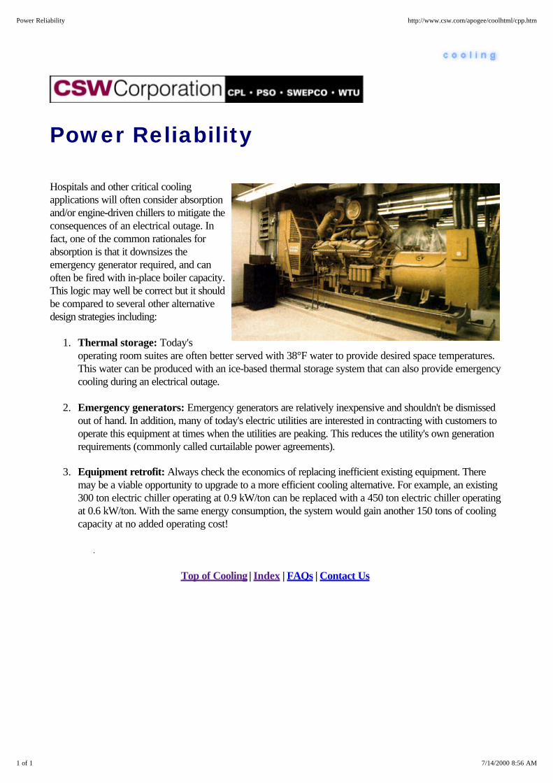
Power Reliability
Hospitals and other critical coolingapplications will often consider absorptionand/or engine-driven chillers to mitigate theconsequences of an electrical outage. Infact, one of the common rationales forabsorption is that it downsizes theemergency generator required, and canoften be fired with in-place boiler capacity.This logic may well be correct but it shouldbe compared to several other alternativedesign strategies including:
1. Thermal storage: Today'soperating room suites are often better served with 38°F water to provide desired space temperatures.This water can be produced with an ice-based thermal storage system that can also provide emergencycooling during an electrical outage.
2. Emergency generators: Emergency generators are relatively inexpensive and shouldn't be dismissedout of hand. In addition, many of today's electric utilities are interested in contracting with customers tooperate this equipment at times when the utilities are peaking. This reduces the utility's own generationrequirements (commonly called curtailable power agreements).
3. Equipment retrofit: Always check the economics of replacing inefficient existing equipment. Theremay be a viable opportunity to upgrade to a more efficient cooling alternative. For example, an existing300 ton electric chiller operating at 0.9 kW/ton can be replaced with a 450 ton electric chiller operatingat 0.6 kW/ton. With the same energy consumption, the system would gain another 150 tons of coolingcapacity at no added operating cost!
Top of Cooling | Index | FAQs | Contact Us
1 of 1 7/14/2000 8:56 AM
Power Reliability http://www.csw.com/apogee/coolhtml/cpp.htm
Problems - Water Towers
Water Towers - High kW/ton and/or Inadequate Tonnage
Water Towers - Faulty Or Missing Nozzles
Water Towers - Faulty Or Missing Fill
Water Towers - Silt, Sediment, Or Slime In The Tower Basin
Water Towers - Air Flow Problems
Water Tower Problems - Tower Size
Water Towers - Hydraulic Problems
Top of Cooling | Index | FAQs | Contact Us
1 of 1 7/14/2000 8:57 AM
Problems - Water Towers http://www.csw.com/apogee/coolhtml/cxpw.htm

Water Towers - High kW/ton and/orInadequate Tonnage
Most chillers operate pretty close to manufacturer's specifications if the condenser and evaporator watertemperatures and flow are reasonably close to design conditions. Therefore, these are the first things to checkif a chiller is either not delivering expected capacity or using more energy than expected. Since the condenser isoften exposed to the elements and thereby subject to fouling and deterioration, this is the first area to check.Common problems here include:
1. Poor cooling tower performance (including everything from broken fill to poor water distribution overtower fill),
2. Hydraulic and/or air flow problems (where inadequate water is being sent to active towers, air flow tothe tower is restricted, or air leaving the tower is being drawn back into the tower).
3. Condenser fouling due to improper cooling tower treatment or inadequate filtration.
Most of these problems can be identified simply by observing tower operation.
Top of Cooling | Index | FAQs | Contact Us
1 of 1 7/14/2000 8:59 AM
Water Towers - High kW/ton and/or Inadequate Tonnage http://www.csw.com/apogee/coolhtml/cpwh.htm

Water Towers - Faulty Or MissingNozzles
Water fed to the top of the cooling tower entersdistribution boxes and passes through orifices and nozzles.If these nozzles are plugged, missing, broken, or water isnot being evenly distributed, the tower fill will not receivean even water spray. The maintenance staff is also proneto break these nozzles or force them loose in theirfrustration to keep them running clear. Blocked nozzlescommonly cause the distribution boxes to overflow, andbroken or missing nozzles typically cause water to stream unevenly on the outside of the tower.
Top of Cooling | Index | FAQs | Contact Us
1 of 1 7/14/2000 9:00 AM
Water Towers - Faulty Or Missing Nozzles http://www.csw.com/apogee/coolhtml/cpwn.htm

Water Towers - Faulty Or Missing Fill
Some older cooling towers use wood slats supported onwire or wood frames. These are very inefficient comparedto today's modern structured tower fills. The old,inefficient fills cause the water to fall too rapidly throughthe tower, minimizing the evaporation rate andconsequently the temperature drop. Similarly, missing fillresults in water leaving the distribution boxes to falldirectly and quickly to the tower basin. The easiest way tospot fill problems is to look across the tower basin for uneven water flow. The tower should look like auniform heavy rainstorm from this vantage point -- not a series of waterfalls.
Top of Cooling | Index | FAQs | Contact Us
1 of 1 7/14/2000 8:59 AM
Water Towers - Faulty Or Missing Fill http://www.csw.com/apogee/coolhtml/cpwf.htm

Water Towers - Silt, Sediment, OrSlime In The Tower Basin
Running your hand along the tower basin should not pickup very much sediment or slime. Sediment implies eitherthat the tower is not being blown down adequately (whichcould result in scale buildup in the chiller condenser), orinadequate water filtration. Slime implies the cooling towerwater chemistry is out of balance which will quickly foulchiller condensers. The basin water should be clear andessentially colorless. An excellent way to check forpotential condenser fouling is to compare the chiller'sleaving condenser water temperature with the temperatureat which refrigerant is condensing (you can do this usingcondenser pressure and a refrigerant properties table). While this can be tedious for the uninitiated, it's almostalways feasible to do this in the field with simple instrumentation. Comparing this information with equipmentdata from the manufacturer often pinpoints the problems.
Top of Cooling | Index | FAQs | Contact Us
1 of 1 7/14/2000 9:00 AM
Towers - Silt, Sediment, Or Slime In The Tower Basin http://www.csw.com/apogee/coolhtml/cpws.htm

Water Towers - Air Flow Problems Cooling towers tend to be thought of as "ugly" by the designcommunity, and efforts to hide or disguise them often create airflow problems. For example, shrubs, louvers, and even placementtoo close to buildings can "starve" the tower for fresh air and/orcause some of the warm, humid discharge air to short circuit anddeteriorate tower performance.
Top of Cooling | Index | FAQs | Contact Us
1 of 1 7/14/2000 9:04 AM
Water Towers - Air Flow Problems http://www.csw.com/apogee/coolhtml/cpwa.htm

Water Water Tower Problems - TowerSize
Oversizing a cooling tower represents one of the best energy efficiency investments that can be made since itwill deliver colder condenser water on design days as well as reduce energy consumption throughout the restof the year. In essence, the tower surface area is made larger and more air is brought into contact with thesame amount of cooling tower water. While tower fan power may be slightly higher on design days, theoffsetting energy savings in the chiller itself usually more than compensates.
Top of Cooling | Index | FAQs | Contact Us
1 of 1 7/14/2000 9:04 AM
Water Tower Problems - Tower Size http://www.csw.com/apogee/coolhtml/cpwt.htm
Water Towers - Hydraulic Problems
Today's high efficiency electric chillers normally use about 2.8 gpm of condenser water per ton. Pumps arepurchased to produce this flow for a given cooling tower height and total frictional resistance in the piping andchiller system. Pump impellers exposed to sand and silt can erode, and fouled or plugged condensers cansignificantly increase pumping resistance. The combined result is reduced condenser flow. One of the earliestwarning signs of this problem shows up in the temperature rise across the condenser. If it's higher than thatspecified in the chiller design (commonly from 85°F to 95°F or a 10°F range), some form of flow problemprobably exists.
Top of Cooling | Index | FAQs | Contact Us
1 of 1 7/14/2000 9:04 AM
Water Towers - Hydraulic Problems http://www.csw.com/apogee/coolhtml/cpwp.htm

High Power Costs
Failing Chillers
Poor Operational Planning
Multiple Chillers: Absorption & Electric Hybrids
Top of Cooling | Index | FAQs | Contact Us
1 of 1 7/14/2000 9:05 AM
High Power Costs http://www.csw.com/apogee/coolhtml/cxph.htm

Failing Chillers
Demand charges can be accidentally set higher than normal when the lead chiller fails, since lead chillers tendto be backed up by less efficient and less reliable machines. The worst case is where a lead chiller failsfollowed quickly by the failure of one or more of the less efficient machines. Once the chillers are finally putback on line they all tend to "load up" to maximum tonnage levels to recover the building and thereby set anunusually high electrical demand. Where the electric rate schedule has a demand ratchet, this can be quitecostly. There are several potential solutions including:
1. Better preventative maintenance (so that chiller failure is less likely in the first place),
2. Chiller replacement coupled with load reduction (e.g., through improved lighting or better HVACcontrol).
Top of Cooling | Index | FAQs | Contact Us
1 of 1 7/14/2000 9:06 AM
Failing Chillers http://www.csw.com/apogee/coolhtml/cphf.htm

Poor Operational Planning
Operators may not understand the cost impact of starting a chiller for a few hours a day once or twice amonth. They may choose to start a chiller in answer to a "hot call" which might be better solved throughwindow treatments, improved HVAC control, upgraded lighting efficiency, or even by relocating the worker. Itmay also be less expensive to just let the chilled water temperature rise, if it won't be for a very long period oftime. Clearly, operator training and sensitivity is essential here, along with an awareness of the financial impactof chiller operation.
Top of Cooling | Index | FAQs | Contact Us
1 of 1 7/14/2000 9:06 AM
Poor Operational Planning http://www.csw.com/apogee/coolhtml/cphp.htm
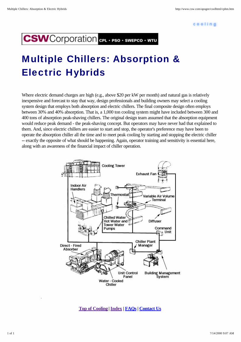
Multiple Chillers: Absorption &Electric Hybrids
Where electric demand charges are high (e.g., above $20 per kW per month) and natural gas is relativelyinexpensive and forecast to stay that way, design professionals and building owners may select a coolingsystem design that employs both absorption and electric chillers. The final composite design often employsbetween 30% and 40% absorption. That is, a 1,000 ton cooling system might have included between 300 and400 tons of absorption peak-shaving chillers. The original design team assumed that the absorption equipmentwould reduce peak demand - the peak-shaving concept. But operators may have never had that explained tothem. And, since electric chillers are easier to start and stop, the operator's preference may have been tooperate the absorption chiller all the time and to meet peak cooling by starting and stopping the electric chiller-- exactly the opposite of what should be happening. Again, operator training and sensitivity is essential here,along with an awareness of the financial impact of chiller operation.
Top of Cooling | Index | FAQs | Contact Us
1 of 1 7/14/2000 9:07 AM
Multiple Chillers: Absorption & Electric Hybrids http://www.csw.com/apogee/coolhtml/cphm.htm
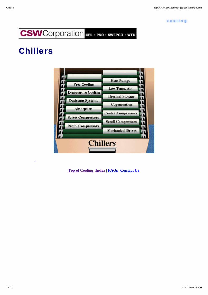
Chillers
Top of Cooling | Index | FAQs | Contact Us
1 of 1 7/14/2000 9:23 AM
Chillers http://www.csw.com/apogee/coolhtml/cxc.htm

Free Cooling
"Free Cooling" is the production of chilled water without operating the chillers. Free cooling is not really free asthe chilled and tower water pumps and the tower fan(s) must operate.
The heat removed from the building by the chilled water coils is rejected by one of these alternatives.
1. Refrigeration Migration
2. Strainer Cycle
3. Plate and Frame Heat Exchanger
Select from these areas of interest . . .
Refrigerant Migration Strainer Cycle
Plate and Frame
Top of Cooling | Index | FAQs | Contact Us
1 of 1 7/14/2000 9:23 AM
Free Cooling http://www.csw.com/apogee/coolhtml/cxcf.htm

Free Cooling - Refrigerant Migration
One method for reducing the energy consumption of a centrifugal water chiller is to add a refrigerant-migrationfree cooling cycle. This type of free cooling is based on the principle that refrigerant migrates to the coldestpoint in a refrigeration circuit.
When water returning from the cooling tower is colder than the chilled water, refrigerant pressure within thecondenser is lower than that in the evaporator. This pressure differential drives the refrigerant vapor "boiledoff" in the evaporator to the condenser, where it liquifies and flows by gravity back to the evaporator. As longas the proper pressure difference exists between the evaporator and condenser, refrigerant flow and theconsequent free cooling continues.
Under favorable conditions, refrigerant-migration free cooling can provide as much as 40 percent of thechiller's design tonnage if the chiller is designed appropriately. Since the chiller and free cooling cycle cannotoperate simultaneously, free cooling of this type can only be used when the cooling capacity of the tower wateris sufficient to meet the entire building load.
Little, if any, free cooling capacity is available when the ambient wet bulb temperature is above 50°F.Accessories such as chilled water pumps, condenser water pumps and cooling tower fans continue to operatein the conventional manner while the chiller operates in the free cooling mode. The energy cost savings realizedfrom free cooling operation results from the compressor's inactivity during this cycle. The cooling tower mustbe designed for winter operation.
Top of Cooling | Index | FAQs | Contact Us
1 of 1 7/13/2000 10:05 PM
Free Cooling - Refrigerant Migration http://www.csw.com/apogee/coolhtml/ccfr.htm
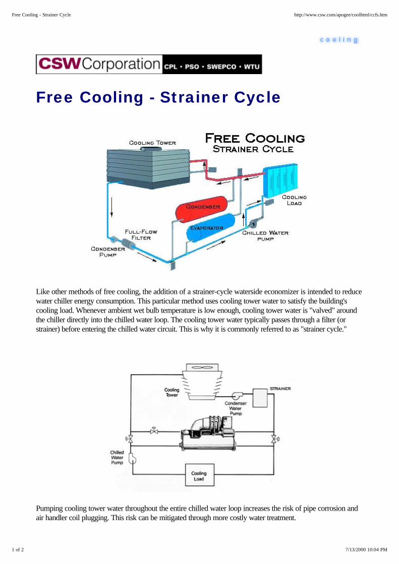
Free Cooling - Strainer Cycle
Like other methods of free cooling, the addition of a strainer-cycle waterside economizer is intended to reducewater chiller energy consumption. This particular method uses cooling tower water to satisfy the building'scooling load. Whenever ambient wet bulb temperature is low enough, cooling tower water is "valved" aroundthe chiller directly into the chilled water loop. The cooling tower water typically passes through a filter (orstrainer) before entering the chilled water circuit. This is why it is commonly referred to as "strainer cycle."
Pumping cooling tower water throughout the entire chilled water loop increases the risk of pipe corrosion andair handler coil plugging. This risk can be mitigated through more costly water treatment.
1 of 2 7/13/2000 10:04 PM
Free Cooling - Strainer Cycle http://www.csw.com/apogee/coolhtml/ccfs.htm

Strainer cycle economics are limited since free cooling is only available when the cooling load can be satisfiedwith cooling tower water. The cooling tower must be designed for winter operation.
Top of Cooling | Index | FAQs | Contact Us
2 of 2 7/13/2000 10:04 PM
Free Cooling - Strainer Cycle http://www.csw.com/apogee/coolhtml/ccfs.htm

Evaporative Cooling
Evaporative cooling supply air can reduce the energy consumed by mechanical cooling equipment. The twogeneral types of evaporative cooling are direct and indirect systems. The effectiveness of either of thesemethods is directly dependent on the low wet bulb temperature in the supply airstream. This is why thesesystems are popular in desert climates.
In some applications, the two types are combined as shown here.
Select from these areas of interest . . .
Evaporative Cooling - Direct Evaporative Cooling - Indirect
Top of Cooling | Index | FAQs | Contact Us
1 of 1 7/14/2000 9:27 AM
Evaporative Cooling http://www.csw.com/apogee/coolhtml/cxce.htm

Evaporative Cooling - Direct
Direct evaporative cooling introduces water directly into the supply airstream (usually with a spray or somesort of wetted media). As the water absorbs heat from the air, it evaporates. While this process lowers the drybulb temperature of the supply airstream, it also increases its wet bulb temperature by raising the air moisturecontent.
While an evaporative cooling system can effectively reduce the required capacity of the mechanical coolingequipment, it usually does not eliminate the need for a conventional cooling coil (except in certain arid regionsof the country). Additional static pressure typically around 0.2 to 0.3 inches water column is required by the airhandling system whenever evaporative coils are used in conjunction with a conventional cooling coil.
1 of 2 7/14/2000 9:33 AM
Evaporative Cooling - Direct http://www.csw.com/apogee/coolhtml/cced.htm

Top of Cooling | Index | FAQs | Contact Us
2 of 2 7/14/2000 9:33 AM
Evaporative Cooling - Direct http://www.csw.com/apogee/coolhtml/cced.htm

Evaporative Cooling - Indirect
Indirect evaporative cooling uses an additional waterside coil to lower supply air temperature. The added coilis placed ahead of the conventional cooling coil in the supply airstream, and is piped to a cooling tower wherethe evaporative process occurs. Because evaporation occurs elsewhere, this method of "precooling" does notadd moisture to the supply air, but is less effective than direct evaporative cooling. That is, it will not cool air toas low a temperature at the same outside air wet bulb.
1 of 2 7/14/2000 9:35 AM
Evaporative Cooling - Indirect http://www.csw.com/apogee/coolhtml/ccei.htm
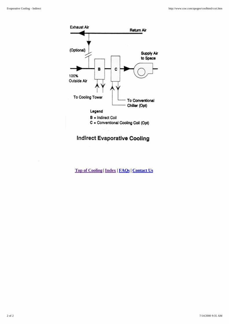
Top of Cooling | Index | FAQs | Contact Us
2 of 2 7/14/2000 9:35 AM
Evaporative Cooling - Indirect http://www.csw.com/apogee/coolhtml/ccei.htm

Desiccant Systems
Commercial cooling equipment dehumidifies air by dropping its temperature below the dew point, causingwater to condense on the coil. From there it is drained from the unit. Most commercial space is maintained at~50% humidity so circulating 44°F water through the conventional cooling coils will usually do. But what if thespace requires 15-20% humidity, say to handle some humidity-sensitive material? Achieving that humidity inthe space would require a much colder coil temperature. Needless to say, after the water was removed, the airwould have to be reheated. This is the domain of desiccant based systems. Desiccant systems removemoisture directly from the air without cooling it. In fact, they usually end up heating the air.
Consequently, desiccant based systems tend to be used in a series with conventional cooling equipment. Thecommon design approach uses desiccant to remove the moisture (i.e. latent load) while conventional coolingremoves the sensible load. As in almost any technical area, there are several alternatives. The two mostcommon commercial designs uses a honeycomb wheel impregnated with a solid crystalline material (such aslithium chloride or silica gel) or a liquid spray into the air stream.
Both capture the moisture in the air as it passes through.Another alternative to these desiccant concepts worthy ofside-by-side comparison is the heat pipe, which is muchsimpler and may provide the same performance.
Desiccant systems are widely used in low humidity applicationssuch as pharmaceutical powder production and packaging.They have also been used in supermarkets where lower spacehumidity has been shown to improve the energy performanceof case work, increase occupant comfort and may evenimprove sales. The two key questions are : Are they costeffective to install? Do they represent the best system to installin a given application? Both of these questions should beaddressed by a qualified professional.
If they fit and are correctly designed, desiccant systems canalso produce these benefits:
1. Eliminate condensation on cooling coils and in drip pans,and reduce humidity levels in ducts. This will virtually eliminatethe growth of mold, mildew, and bacteria. The combinationcan reduce maintenance and help avoid indoor air qualityproblems.
2. Lower humidity levels in occupied spaces providesequivalent comfort levels at higher ambient temperatures. This could allow chilled water set-points to be raisedand there-by save energy and reduce system operating costs.
1 of 2 7/14/2000 9:41 AM
Desiccant Systems http://www.csw.com/apogee/coolhtml/ccd.htm
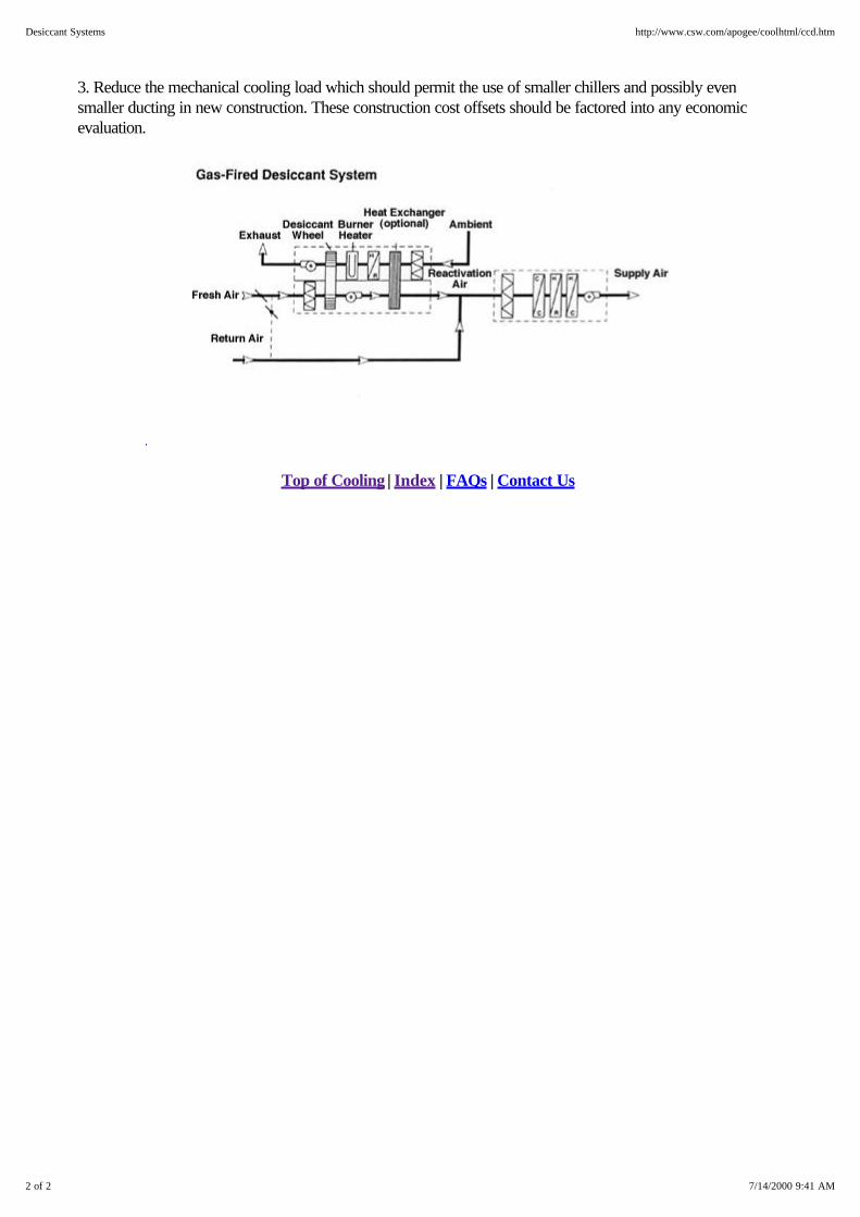
3. Reduce the mechanical cooling load which should permit the use of smaller chillers and possibly evensmaller ducting in new construction. These construction cost offsets should be factored into any economicevaluation.
Top of Cooling | Index | FAQs | Contact Us
2 of 2 7/14/2000 9:41 AM
Desiccant Systems http://www.csw.com/apogee/coolhtml/ccd.htm
Absorption Chillers
Absorption Cycle
Two Stage Absorption Chillers
Direct-Fired Absorption Chillers
Waste Heat Fired Absorption Chillers
Absorption Chillers - Maintenance Considerations
Top of Cooling | Index | FAQs | Contact Us
1 of 1 7/14/2000 9:42 AM
Absorption Chillers http://www.csw.com/apogee/coolhtml/cxca.htm

Absorption Cycle The absorption cycle uses a heat-driven concentration difference to move refrigerant vapors (usually water)from the evaporator to the condenser. The high concentration side of the cycle absorbs refrigerant vapors(which, of course, dilutes that material). Heat is then used to drive off these refrigerant vapors therebyincreasing the concentration again. Lithium bromide is the most common absorbent used in commercial coolingequipment, with water used as the refrigerant. Smaller absorption chillers sometimes use water as theabsorbent and ammonia as the refrigerant. As you can probably guess, the absorption chiller must operate atvery low pressures (about l/l00th of normal atmospheric pressure) for the water to vaporize at a cold enoughtemperature (e.g., at ~ 40°F) to produce 44°F chilled water.
The simplified diagram here illustrates the overall flow path. Starting with the evaporator, water at about 40°Fis evaporating off the chilled water tubes, thereby bringing the temperature down from the 54°F being returnedfrom the air handlers to the required 44°F chilled water supply temperature. One ton of cooling evaporatesabout 12 pounds of water per hour in this step.
This water vapor is absorbed by the concentrated lithium bromide solution due to its hygroscopiccharacteristics. The heat of vaporization and the heat of solution are removed using cooling water at this step.The solution is then pumped to the concentrator at a higher pressure where heat is applied (using steam or hotwater) to drive off the water and thereby re-concentrate the lithium bromide.
The water driven off by the heat input step is then condensed (using cooling tower water), collected, and thenflashed to the required low temperature (40°F in our illustration) to complete the cycle. Since water is movingthe heat from the evaporator to the condenser, it serves as the refrigerant in this cycle. There are alsoabsorption chillers in use (e.g. in motor homes) that use ammonia as the refrigerant in the same cycle.
1 of 2 7/14/2000 9:43 AM
Absorption Cycle http://www.csw.com/apogee/coolhtml/ccaa.htm

The absorbent is the material that is used to maintain the concentration difference in the machine. Mostcommercial absorption chillers use lithium bromide. Lithium bromide has a very high affinity for water, isrelatively inexpensive and non-toxic. However, it can be highly corrosive and disposal is closely controlled.Water of course is extremely low cost and safety simply isn't an issue.
Absorption Chillers
Absorption chillers are available in two types:
1. Single Effect (Stage) Units using low pressure (20 psig or less) as the driving force. These units typicallyhave a COP of 0.7 and require about 18pph per ton of 9 psig steam at the generator flange (aftercontrol valve) at ARI standard rating conditions.
2. Double Effect (2-Stage) Units are available as gas-fired (either direct gas firing, or hot exhaust gas froma gas-turbine or engine) or steam-driven with high pressure steam (40 to 140 psig). These units typicallyhave a COP of 1.0 to 1.2. Steam driven units require about 9 to 10 pph per ton of 114 psig inputsteam at ARI standard rating conditions. Gas-fired units require an input of about 10,000 to 12,000Btuh HHV per ton of cooling at ARI standard rating conditions. To achieve this improved performancethey have a second generator in the cycle and require a higher temperature energy source.
Top of Cooling | Index | FAQs | Contact Us
2 of 2 7/14/2000 9:43 AM
Absorption Cycle http://www.csw.com/apogee/coolhtml/ccaa.htm
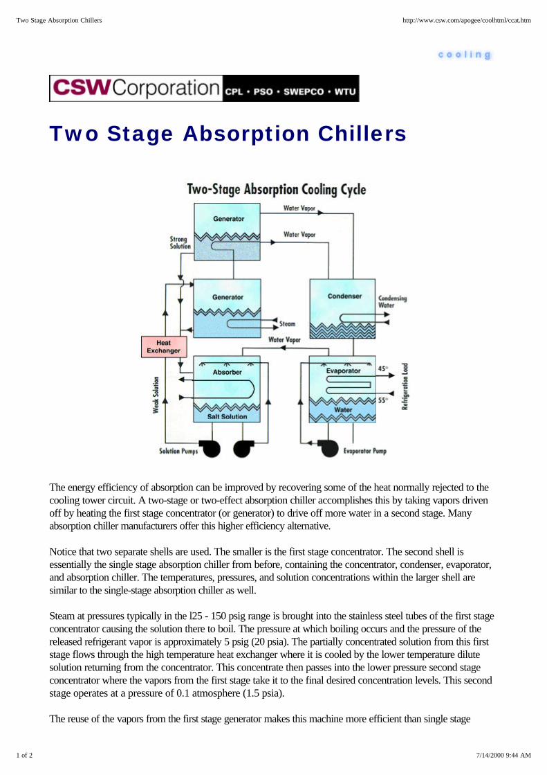
Two Stage Absorption Chillers
The energy efficiency of absorption can be improved by recovering some of the heat normally rejected to thecooling tower circuit. A two-stage or two-effect absorption chiller accomplishes this by taking vapors drivenoff by heating the first stage concentrator (or generator) to drive off more water in a second stage. Manyabsorption chiller manufacturers offer this higher efficiency alternative.
Notice that two separate shells are used. The smaller is the first stage concentrator. The second shell isessentially the single stage absorption chiller from before, containing the concentrator, condenser, evaporator,and absorption chiller. The temperatures, pressures, and solution concentrations within the larger shell aresimilar to the single-stage absorption chiller as well.
Steam at pressures typically in the l25 - 150 psig range is brought into the stainless steel tubes of the first stageconcentrator causing the solution there to boil. The pressure at which boiling occurs and the pressure of thereleased refrigerant vapor is approximately 5 psig (20 psia). The partially concentrated solution from this firststage flows through the high temperature heat exchanger where it is cooled by the lower temperature dilutesolution returning from the concentrator. This concentrate then passes into the lower pressure second stageconcentrator where the vapors from the first stage take it to the final desired concentration levels. This secondstage operates at a pressure of 0.1 atmosphere (1.5 psia).
The reuse of the vapors from the first stage generator makes this machine more efficient than single stage
1 of 2 7/14/2000 9:44 AM
Two Stage Absorption Chillers http://www.csw.com/apogee/coolhtml/ccat.htm
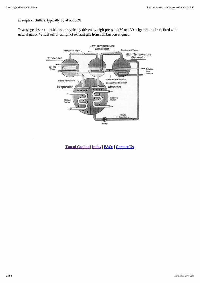
absorption chillers, typically by about 30%.
Two-stage absorption chillers are typically driven by high-pressure (60 to 130 psig) steam, direct-fired withnatural gas or #2 fuel oil, or using hot exhaust gas from combustion engines.
Top of Cooling | Index | FAQs | Contact Us
2 of 2 7/14/2000 9:44 AM
Two Stage Absorption Chillers http://www.csw.com/apogee/coolhtml/ccat.htm
Direct-Fired Absorption Chillers
Direct-fired absorption chillers utilize a burner as the heat input for the absorption cooling cycle. Most operateeither on natural gas or No. 2 fuel oil. Since the heat input is at a very high temperature, they achieve a veryhigh efficiency for the absorption cycle...something approaching 12,000 Btu of fuel input for each ton hour ofcooling output. The absorption cycle itself is virtually identical to that of the two-stage steam absorptionchillers. However, unlike most steam absorption chillers, the direct-fired absorption chiller lends itself fairlyreadily to "chiller-heater" applications where both cooling and heating are achieved in the same unit. This canresult in a smaller footprint for the boiler room in some situations.
Select from these areas of interest . . .
Direct-Fired Absorption Chillers - Advantages Direct-Fired Absorption Chillers - Disadvantages
Top of Cooling | Index | FAQs | Contact Us
1 of 1 7/14/2000 9:45 AM
Direct-Fired Absorption Chillers http://www.csw.com/apogee/coolhtml/cxcad.htm
Direct-Fired Absorption Chillers -Advantages
Where a boiler can be eliminated by the dual heating and cooling capability of this machine, the cost and spacesavings can be a significant. In addition, steam is not required, which can be important in situations where localcodes require licensed boiler operators for steam-driven units but permit unmanned operation of direct-firedabsorption chillers.
Top of Cooling | Index | FAQs | Contact Us
1 of 1 7/14/2000 9:46 AM
Direct-Fired Absorption Chillers - Advantages http://www.csw.com/apogee/coolhtml/ccada.htm

Direct-Fired Absorption Chillers -Disadvantages
Direct-fired absorption chillers require a stack to vent combustion products. This is not necessary in asteam-fired unit. In addition, the first cost of direct-fired units are higher than steam driven units. Maintenancecosts on the heat rejection circuit tend to be higher due to more rapid scaling. Also be careful to checkwarranted life of absorption chiller heat transfer surfaces (especially the generator section) and the refrigerantand solution pumps. All absorption chillers use electric power to operate these pumps, the condenser waterpumps and cooling tower fans. They also use more water as they must reject more heat and require largercooling towers.
Absorption chillers are more difficult than electric chillers to put on-line (start up) and to take off-line (shutdown) as they require a dilution cycle. All of these issues should be addressed in discussions withmanufacturers, designers and mechanical contractors.
Top of Cooling | Index | FAQs | Contact Us
1 of 1 7/14/2000 9:47 AM
Direct-Fired Absorption Chillers - Disadvantages http://www.csw.com/apogee/coolhtml/ccadd.htm
Waste Heat Fired Absorption Chillers
Most absorption chillers use either steam or fuel for heat input. But, waste heat from process or a cogenerationsystem can also be used in the absorption process.
Select from these areas of interest . . .
Hot Water Steam Hot Air
Top of Cooling | Index | FAQs | Contact Us
1 of 1 7/14/2000 9:46 AM
Waste Heat Fired Absorption Chillers http://www.csw.com/apogee/coolhtml/cxcaw.htm
Waste Heat Fired Absorption Chillers- Hot Water
The performance of absorption chillers is extremely dependent upon the entering hot water temperature andflow rate. Where water temperatures are over 250°F, as little as 1.2- 1.5 gallons per minute of hot water canproduce one ton of cooling. For example, a 120 gpm waste heat stream at 250°F can probably produce80-100 tons of cooling. However, the same size stream at 200°F may produce only half as much cooling.Additionally, the absorption equipment must be derated for lower hot water supply temperatures. Forexample, a chiller that can produce a nominal 560 tons with 250°F hot water will produce about 534 tons with240°F, 430 tons with 220°F, and only 375 tons with 210°F hot water. This deration of capacity seriouslyimpacts the economics as the first cost per ton rapidly increases. Remember also that absorption chillers firedwith hot water will only reduce that water temperature ~ 30-50°F for return to the heat source. This tends tolimit the viability waste heat recovery.
Top of Cooling | Index | FAQs | Contact Us
1 of 1 7/14/2000 9:48 AM
Waste Heat Fired Absorption Chillers - Hot Water http://www.csw.com/apogee/coolhtml/ccawh.htm
Waste Heat Fired Absorption Chillers- Steam
Waste steam from a cogeneration system obviously produces the same level of cooling as boiler generatedsteam, Low pressure waste steam sources (say 14 psig) typically require 18-20 pounds of steam per hour toproduce one ton of cooling in a single-stage absorption chiller. That performance improves to 10-12 poundsper ton-hour of steam when steam pressures are in the 50 to 130 psig range and used in a 2-stage (doubleeffect) absorption chiller.
Steam absorption chillers are nominally rated as follows:
Single stage: 9 psig at generator flange
Two stage: 114 psig steam input pressure.
Capacity ratings are decreased as steam pressure drops below nominal. For example, a nominal 100-ton unit'scapacity will drop to 84 tons with 78.5 psig steam.
Top of Cooling | Index | FAQs | Contact Us
1 of 1 7/14/2000 9:48 AM
Waste Heat Fired Absorption Chillers - Steam http://www.csw.com/apogee/coolhtml/ccaws.htm
Waste Heat Fired Absorption Chillers- Hot Air
Direct-fired absorption chillers can often be modified to accept hot air or exhaust from a gas turbine or engine.Performance is almost totally dependent upon air temperature, For example, waste heat air temperatures °F orhigher offer performance similar to direct-fired absorption chillers where every 13,000 Btu of heat recoveredproduces one ton of cooling. When calculating heat recovery, remember to assume waste heat leaving theabsorption chiller at 375° to 400°F (this means the absorption chiller will not reclaim all of the waste heatpotential).
For exhaust gas heat recovery
Chilling capacity (tons) / 40,950 = m x (Tg - 375)
Heating capacity (Btuh) = m x (Tg - 375) x 0.257
where m = exhaust gas flow rate in pounds per hour Tg = exhaust gas inlet temperature in °F 40,950 = cooling constant representing average gas specific heat, interconnect efficiency, cooling COP and the conversionfrom Btuh to tons 0.257 = heating constant representing average gas specific heat and the interconnect efficiency 375 = minimum temperature of exhaust gas leaving chiller in °F.
Top of Cooling | Index | FAQs | Contact Us
1 of 1 7/14/2000 9:48 AM
Waste Heat Fired Absorption Chillers - Hot Air http://www.csw.com/apogee/coolhtml/ccawa.htm

Absorption Chillers - MaintenanceConsiderations
Properly designed and installed absorption chillers can function without full time attendants. The machine canbe started and brought on line with simple time clocks or energy management systems. Non-condensables areautomatically purged and the operator can schedule normal routine maintenance. Obviously, local buildingcodes may dictate that a full time operator is, or is not, required. This, in turn, is often a function of the size ofthe equipment, steam pressure, etc. Always consult local codes when considering these issues.
There are three primary maintenance areas: mechanical components, heat transfer components, and controls.The following segments discuss mechanical and heat transfer maintenance areas.
Select from these areas of interest . . .
Mechanical Components Heat Transfer Components
Pump Maintenance Prolonged or Seasonal Shutdown Purging Non-condensable Gases
Top of Cooling | Index | FAQs | Contact Us
1 of 1 7/14/2000 9:50 AM
Absorption Chillers - Maintenance Considerations http://www.csw.com/apogee/coolhtml/cxcam.htm

Absorption Chiller Maintenance -Mechanical Components
One manufacturer's absorption chillers has a single motor/multiplepump configuration for refrigerant and solution flow and a purgeunit. Other manufacturers use individual hermetic solution andrefrigerant pumps cooled and lubricated by the pumped solution.Another uses open motors with a shaft seal.
Pictured here are two hermetic, refrigerant cooled and lubricatedpump assemblies. The hermetically sealed motor drives thesolution and refrigerant pump impellers. In this multiple pumparrangement, motor coolant and lubrication is by the fluid beingpumped. Hermetic pump designs eliminate the need for externalshaft seals – a maintenance item and potential source of airleakage.
Top of Cooling | Index | FAQs | Contact Us
1 of 1 7/14/2000 9:51 AM
Absorption Chiller Maintenance - Mechanical Components http://www.csw.com/apogee/coolhtml/ccamm.htm
Absorption Chiller Maintenance - HeatTransfer Components
The life, performance, and cooling capacity of absorption equipment hinges on keeping heat transfer surfacesfree of scale and sludge. Even a thin coating of scale can significantly reduce capacity. Therefore, coolingtower water chemistry is critical, and failure to properly treat this water could void manufacturer warranties.
Scale deposits are best removed chemically. Sludge is best removed mechanically, usually by removing theheaders and loosening the deposits with a stiff bristle brush. The loosened material is then flushed from thetubes with clear water.
Top of Cooling | Index | FAQs | Contact Us
1 of 1 7/14/2000 9:54 AM
Absorption Chiller Maintenance - Heat Transfer Components http://www.csw.com/apogee/coolhtml/ccamh.htm

Absorption Chiller Maintenance -Pump Maintenance
When the electric motor and pump bearings fail, one design permits replacement of pump parts withoutremoving the lithium bromide solution from the machine. The first step is closing the hand valves in thelubrication circuit, disconnecting the electrical supply, and removing the motor. The pump shaft seal maintainsmachine vacuum. Major pump repairs are accommodated by charging the machine with nitrogen toatmospheric pressure. Once complete, the machine is evacuated, and pump parts removed and repaired orreplaced. Other designs require a more complicated replacement procedure.
Pump maintenance begins with the magnetic strainer which must be cleaned 2 weeks after the initial startup andat the mid-point in the cooling season. Shaft seals should be examined for wear at three year intervals.
Top of Cooling | Index | FAQs | Contact Us
CSW
1 of 1 7/14/2000 10:07 AM
Absorption Chiller Maintenance - Pump Maintenance http://www.csw.com/apogee/coolhtml/ccamp.htm
Absorption Chiller Maintenance -Prolonged or Seasonal Shutdown
In the case of seasonal or prolonged shutdown, refrigerant may migrate from the evaporator to the absorptionchiller causing a low refrigerant level in the evaporator pan and piping. Since refrigerant is used to lubricatepump and motor bearings, lubrication from an auxiliary source must be provided during the startup phase ofoperation. Once an operating charge of refrigerant has been recovered from the solution, the machine may bereturned to normal operation.
This auxiliary circuit is usually established by connecting city water to the external connections of the pumplubrication piping.
In all cases, follow the manufacturer's recommended procedures.
Top of Cooling | Index | FAQs | Contact Us
1 of 1 7/14/2000 10:10 AM
Absorption Chiller Maintenance - Prolonged or Seasonal Shutdown http://www.csw.com/apogee/coolhtml/ccams.htm

Absorption Chiller Maintenance -Purging Non-condensable Gases
All absorption chillers must be purged of non-condensable gases to maintain performance. The three methodsused are steam jet, solution jet (or "motorless purge"), or a vacuum pump, with the vacuum pump being by farthe most common.
Non-condensable gases migrate to the area of lowest pressure in the absorption chiller (the evaporator) wherea small portion of the vapor is extracted and condensed in the purge unit using cooling water.Non-condensable are then evacuated by the vacuum pump. In normal operation, the purge system shouldoperate about one hour a week. The vacuum pump oil level should be observed, maintained, and changed asnecessary. Oil purge pump motor bearings should be inspected and replaced, and the belt adjusted as needed.In addition, the vacuum pump should be flooded with oil during seasonal shutdown to prevent internalcorrosion.
Purging of non-condensables can be accomplished using a "motorless purge". Where motorless purging isused, an optional vacuum pump can also be used for evacuation.
In all cases, the operator should log purge operation and monitor purge operation trends. Increasing purgeoperation signals increasing in-leakage of air and moisture.
Top of Cooling | Index | FAQs | Contact Us
1 of 1 7/14/2000 10:11 AM
Absorption Chiller Maintenance - Purging Non-condensable Gases http://www.csw.com/apogee/coolhtml/ccamn.htm

Screw Compressors
Screw Compressors - Description
Screw Compressors - Performance
Screw Compressors - First Cost
Screw Compressors - Emissions
Screw Compressors - Operation and Maintenance
Top of Cooling | Index | FAQs | Contact Us
1 of 1 7/14/2000 10:15 AM
Screw Compressors http://www.csw.com/apogee/coolhtml/cxcs.htm
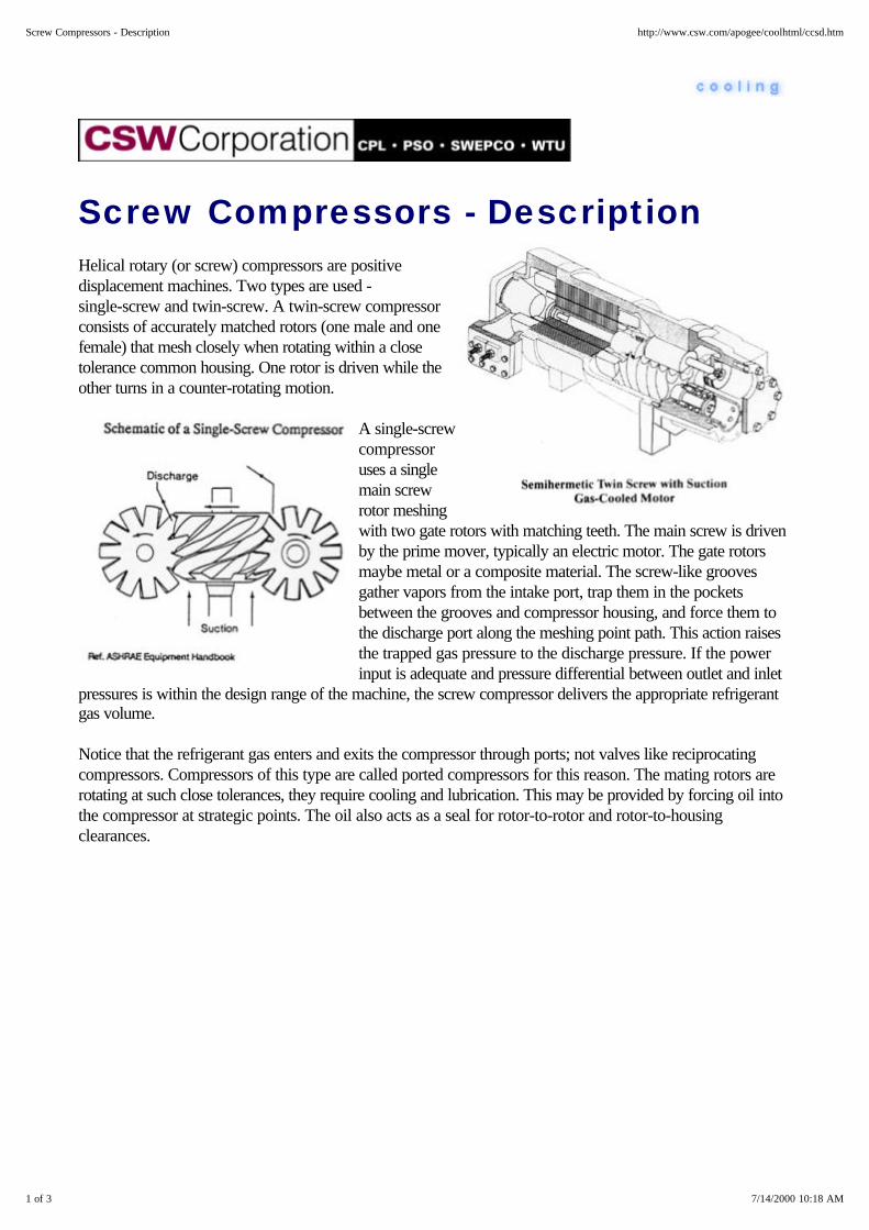
Screw Compressors - Description Helical rotary (or screw) compressors are positivedisplacement machines. Two types are used -single-screw and twin-screw. A twin-screw compressorconsists of accurately matched rotors (one male and onefemale) that mesh closely when rotating within a closetolerance common housing. One rotor is driven while theother turns in a counter-rotating motion.
A single-screwcompressoruses a singlemain screwrotor meshingwith two gate rotors with matching teeth. The main screw is drivenby the prime mover, typically an electric motor. The gate rotorsmaybe metal or a composite material. The screw-like groovesgather vapors from the intake port, trap them in the pocketsbetween the grooves and compressor housing, and force them tothe discharge port along the meshing point path. This action raisesthe trapped gas pressure to the discharge pressure. If the powerinput is adequate and pressure differential between outlet and inlet
pressures is within the design range of the machine, the screw compressor delivers the appropriate refrigerantgas volume.
Notice that the refrigerant gas enters and exits the compressor through ports; not valves like reciprocatingcompressors. Compressors of this type are called ported compressors for this reason. The mating rotors arerotating at such close tolerances, they require cooling and lubrication. This may be provided by forcing oil intothe compressor at strategic points. The oil also acts as a seal for rotor-to-rotor and rotor-to-housingclearances.
1 of 3 7/14/2000 10:18 AM
Screw Compressors - Description http://www.csw.com/apogee/coolhtml/ccsd.htm

The oil is entrained by the flowing refrigerant gas, leaves the compressor, and is recovered by an oil separatorfor reuse (after cooling and filtering). Since the oil sump is on the high pressure side of the system, amechanical pump is not required for oil circulation. The compressive action of the screw itself provide thenecessary pressure differential.
In other designs, subcooled liquid refrigerant injection (instead of oil) coolsand seals the compressor. The use of liquid refrigerant eliminates oilmanagement problems as there are no oil separators or oil recovery systems.The system is sealed, cooled and lubricated with liquid refrigerant which alsoattenuates the noise. Capacity is controlled with two slide valves.
Since the screw compressor is most often driven by a constant speedelectric motor and the screw compressor is a positive displacement machine,the natural tendency is to move a fixed volume of refrigerant gas. This wouldmake refrigeration capacity control difficult. The design uses a slide valvethat opens to vent some gas back to the suction port, reducing both the netgas flow and power input.
Several manufacturers offer packaged water chillers using helical rotary or"screw" compressors. Water-cooled units range in size from 50 tons to over 1200 tons. They normally useHCFC-22 and HFC134a as refrigerants in space cooling designs and ammonia in process refrigeration(particularly food processing). In the smaller sizes, they compete with reciprocating chillers. In larger sizes theycompete with centrifugals.
Screw compressors usually employ hermetic or semi-hermetic designs for higher efficiency, minimum leakage,ease of service, and volume production reasons.
2 of 3 7/14/2000 10:18 AM
Screw Compressors - Description http://www.csw.com/apogee/coolhtml/ccsd.htm

Air- and evaporatively-cooled models can be used from about 60 to 350 tons, and can use open-drives.Chillers using ammonia always use open type compressors, typically with direct-coupled electric motors. Theselection of open or hermetic design depends on the application, refrigerant, and the manufacturer.
Top of Cooling | Index | FAQs | Contact Us
3 of 3 7/14/2000 10:18 AM
Screw Compressors - Description http://www.csw.com/apogee/coolhtml/ccsd.htm

Screw Compressors - Performance
Power input performance for screw chillers has been improving over the years as a result of better designs andcompressor configurations. Overall mechanical and compression efficiencies vary with the compression ratio(absolute discharge pressure divided by suction pressure in psia). These efficiencies range from 75 to 82%,including the losses associated with the hermetic-type refrigerant cooled motor.
At ARI Standard rating conditions (44°F leaving chilled water, 85°F entering condenser water), typical chilleroperation will be about 40°F evaporating and 100°F condensing gauge pressures. A modern screwcompressor has an energy efficiency ratio (EER) in the 14 to 17 range, equal to 0.85 to 0.70 kW per ton atfull load. But remember, chillers don't operate at full load that often and screw compressors are more efficientat part load. Integrated part load performance (a weighted average operating condition) for screw units can beas low as .42 kW per ton.
The chiller's power requirement is likely to be rated in brake horsepower (bhp) in air-cooled applications. Toconvert from bhp to electric input in kW, estimate the motor efficiency (typically about 90 percent efficient)and use the following example of a 100 bhp rating. It would translate to:
(100 bhp x 0.746 kW/bhp) = 82 kW. .9 eff.
Assembled into air-cooled chiller packages or split units in the 20 to 200 ton capacity range screw chillers canbe expected to perform at about 9 to 10 EER, equivalent to 1.15 to 1.06 kW per ton with an average of about1.1 kW per ton.
While they tend to cost more than reciprocating units, air-cooled screw chillers offer better efficiency, infinitelyvariable capacity control, and a higher tolerance to liquid refrigerant entering the compressor.
Top of Cooling | Index | FAQs | Contact Us
1 of 1 7/14/2000 10:21 AM
Screw Compressors - Performance http://www.csw.com/apogee/coolhtml/ccsp.htm
Screw Compressors - First Cost
First cost of rotary screw chiller packages are generally about the same as centrifugals. Smaller sizes tend tobe more expensive than their reciprocating counterparts. Screw compressors are gaining in popularity and thecosts are expected to decrease as production increases. Operating Costs depend on the applicable electricrate and the chiller power input. Screw chiller packages typically have a lower power input than recips but usesomewhat more power than a comparably sized centrifugal at ARI standard conditions. Air-cooled chillerstypically have a higher full-load design kW/ton than water-cooled units. However, the operating profile of thefacility has a major effect actual annual operating costs.
For example, an air-cooled chiller serving a hospital operating room that operates year-round could well havea lower annual electric cost than a comparable water-cooled unit, due to the large number of operating hoursat part-load and low-ambient temperature conditions. A careful energy use and cost analysis performed by aprofessional will indicate the most economical choice.
Additionally, annual maintenance costs must be considered, and these costs tend to be about the same as thecentrifugal counterpart.
If the chiller is driven by a natural gas engine, the added maintenance costs of the engine must also be added.Typically this annually amounts to about $0.012 ton per operating hour.
And Furthermore . . .
Compare - Installed Costs - Chillers
Top of Cooling | Index | FAQs | Contact Us
1 of 1 7/14/2000 10:21 AM
Screw Compressors - First Cost http://www.csw.com/apogee/coolhtml/ccsc.htm
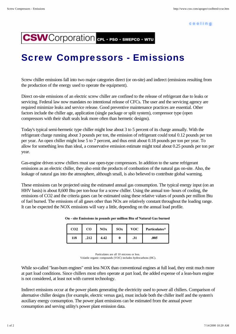
Screw Compressors - Emissions
Screw chiller emissions fall into two major categories direct (or on-site) and indirect (emissions resulting fromthe production of the energy used to operate the equipment).
Direct on-site emissions of an electric screw chiller are confined to the release of refrigerant due to leaks orservicing. Federal law now mandates no intentional release of CFCs. The user and the servicing agency arerequired minimize leaks and service release. Good preventive maintenance practices are essential. Otherfactors include the chiller age, application (single package or split system), compressor type (opencompressors with their shaft seals leak more often than hermetic designs).
Today's typical semi-hermetic type chiller might lose about 3 to 5 percent of its charge annually. With therefrigerant charge running about 3 pounds per ton, the emission of refrigerant could total 0.12 pounds per tonper year. An open chiller might lose 5 to 7 percent, and thus emit about 0.18 pounds per ton per year. Toallow for something less than ideal, a conservative emission estimate might total about 0.25 pounds per ton peryear.
Gas-engine driven screw chillers must use open-type compressors. In addition to the same refrigerantemissions as an electric chiller, they also emit the products of combustion of the natural gas on-site. Also, theleakage of natural gas into the atmosphere, although small, is also believed to contribute global warming.
These emissions can be projected using the estimated annual gas consumption. The typical energy input (on anHHV basis) is about 8,600 Btu per ton-hour for a screw chiller. Using the annual ton- hours of cooling, theemissions of CO2 and the criteria gases can be estimated using these relative values of pounds per million Btuof fuel burned. The emissions of all gases other than NOx are relatively constant throughout the loading range.It can be expected the NOX emissions will vary a little, depending on the annual load profile.
Particulates are all 10 microns or less. Volatile organic compounds (VOC) includes hydrocarbons (HC).
While so-called "lean-burn engines" emit less NOX than conventional engines at full load, they emit much moreat part load conditions. Since chillers most often operate at part load, the added expense of a lean-burn engineis not considered, at least not with current technology.
Indirect emissions occur at the power plants generating the electricity used to power all chillers. Comparison ofalternative chiller designs (for example, electric versus gas), must include both the chiller itself and the system'sauxiliary energy consumption. The power plant emissions can be estimated from the annual powerconsumption and serving utility's power plant emission data.
1 of 2 7/14/2000 10:20 AM
Screw Compressors - Emissions http://www.csw.com/apogee/coolhtml/ccse.htm

Utilities know their typical emissions on a "per kWh" basis.
Top of Cooling | Index | FAQs | Contact Us
2 of 2 7/14/2000 10:20 AM
Screw Compressors - Emissions http://www.csw.com/apogee/coolhtml/ccse.htm

Screw Compressors - Operation andMaintenance
Operation and maintenance (O&M) issues with screw chillers focus on the availability of parts and qualifiedservice technicians. Since these chiller compressors are less common, this can be an important issue for theuser.
Select from these areas of interest . . .
Compare - Operation and Maintenance Costs - Chillers
Top of Cooling | Index | FAQs | Contact Us
1 of 1 7/14/2000 10:16 AM
Screw Compressors - Operation and Maintenance http://www.csw.com/apogee/coolhtml/ccso.htm
Reciprocating Compressors
Reciprocating Compressors - Description
Reciprocating Compressors - Power Requirements
Reciprocating Compressors - First Cost
Reciprocating Compressors - Operating Costs
Reciprocating Compressors - Emissions
Top of Cooling | Index | FAQs | Contact Us
1 of 1 7/14/2000 10:25 AM
Reciprocating Compressors http://www.csw.com/apogee/coolhtml/cxcr.htm

Reciprocating Compressors -Description
Most cooling systems in use today rely on reciprocating piston-type compressors. Reciprocating compressorsare manufactured in three types:
1. Hermetic - compressor-motor assembly contained in a welded steel case, typically used in householdrefrigerators, residential air conditioners, smaller commercial air conditioning and refrigeration units.
2. Semi-hermetic - compressor-motor assembly contained in a casting with no penetration by a rotatingshaft and with gasketed cover plates for access to key parts such as valves and connecting rods.
3. Open - compressor only with shaft seal and external shaft for coupling connection to belt - ordirect-drive using as electric motor or natural gas engine. These are largely used for ammoniarefrigeration applications as hermetic designs cannot be used with ammonia refrigerant, and forengine-driven units.
As the piston nears the bottom of its stroke within thecylinder, the intake valve opens and the refrigerant vaporenters. As the piston rises, the increased pressure closesthe intake valve. Then as the piston nears the top of itsstroke, the exhaust valve opens permitting the vapor at thehigher pressure to exit. Reciprocating compressorcapacity is a function of the bore and stroke of thepiston-cylinder configuration as well as the speed of themachine, and the clearance tolerances. Compressorcapacity is also related to the compression ratio.
Themechanicaldesignis rugged and reliable but has one significant limitation.Reciprocating compressors are designed to handlevapors, not liquids. When liquid enters the cylinder on theintake stroke, it tends to damage the valves on thecompression stroke and possibly the compressor itself.This is why chillers incorporate liquid-to-suction heatexchangers, which assure some level of vapor superheat atthe compressor suction. Capacity is controlled by multiplestaging of smaller compressors or in large multiple cylinder
reciprocating compressors by unloading banks of cylinders on the compressor. This tends to make the machinemost efficient at full load. Therefore, for maximum efficiency recips should generally be operated at full load.This is the reason small compressors are cycled on and off in most residential and small commercial
1 of 2 7/14/2000 10:28 AM
Reciprocating Compressors - Description http://www.csw.com/apogee/coolhtml/ccrd.htm

applications.
Top of Cooling | Index | FAQs | Contact Us
2 of 2 7/14/2000 10:28 AM
Reciprocating Compressors - Description http://www.csw.com/apogee/coolhtml/ccrd.htm

Reciprocating Compressors - PowerRequirements
Due to better valve designs and configurations that reduce pressure losses, power requirements forreciprocating chillers have been improving over the years. Overall mechanical and compression efficienciesvary with the compression ratio, but are generally in the 72 to 78% range including the hermetic-typerefrigerant-cooled 1,750 rpm motor. Compression ratio is computed by dividing the absolute dischargepressure by the suction pressure both measured in psia.
At ARI Standard rating conditions (44°F leaving chilled water, 85°F entering condenser water), typical chillersoperate around 40°F evaporating and 100°F condensing temperatures equivalent to pressures. A modernreciprocating compressor has an energy efficiency ratio (EER) of about 15, equal to 0.79 kW per ton.However, in air-cooled conditions the condensing pressure is likely to run up to a 130°F temperaturecorresponding to pressure, with EERs ranging from about 10.4 up to 11.3, which equate to 1.15 to 1.06 kWper ton.
Assembled into chiller packages in the 20 to 200-plus ton capacities, air-cooled units will typically have EERsranging from 9.0 to 10.9, equal to 1.33 to 1.10 kW per ton with an average of about 1.22 kW per ton. Similarwater-cooled chiller packages will have EERs ranging from 13.1 to as high as 15.8, which equates to 0.92 to0.76 kW per ton with an average of about 0.82 kW per ton.
Manufacturers continue to develop more efficient models. In some cases, scroll compressors are being used, inplace of reciprocating.
Top of Cooling | Index | FAQs | Contact Us
1 of 1 7/14/2000 10:27 AM
Reciprocating Compressors - Power Requirements http://www.csw.com/apogee/coolhtml/ccrp.htm
Reciprocating Compressors - FirstCost
While they are the least efficient of the chiller package options, reciprocating or scroll compressor chillers havea definite first cost advantage in the smaller chiller sizes. The first cost of reciprocating chiller packages is thelowest of the various electric chiller options, certainly when expressed in $ per ton. The compressors arecompetitively priced since they are used in many different chiller models. Plus, many more reciprocating chillersare produced than larger centrifugal and screw type chillers. These economies of scale result in a lower unitcost, especially for models up to about 200 tons.
And Furthermore . . .
Compare - Installed Costs - Chillers
Top of Cooling | Index | FAQs | Contact Us
1 of 1 7/14/2000 10:27 AM
Reciprocating Compressors - First Cost http://www.csw.com/apogee/coolhtml/ccrf.htm

Reciprocating Compressors -Operating Costs
Operating costs will depend on electric rates. Reciprocating chiller packages typically have the highestoperating costs of any of the various electric chiller options when expressed as a kW per ton figure at ARIstandard conditions. Air-cooled chillers typically have a full-load design kW per ton even higher thanwater-cooled units. However, the operating profile of the facility will have a major effect on actual operatingcosts.
For example, an air-cooled chiller serving a hospital operating room suite that operates year-round could wellhave a lower annual electric cost than a comparable water-cooled unit, due to the large number of operatinghours the unit will be operating at part-load and low-ambient temperature conditions. Only a careful energy useanalysis of each application performed by a qualified professional can identify the most economical equipmentchoice.
Maintenance costs must also be factored in. Here are some typical mid-1995 $ per ton annual values.
If the chiller is driven by a natural gas engine, the added maintenance costs of the engine must also be included.Typically this amounts to about $0.012 per ton per operating hour.
And Furthermore . . .
Compare - Operating and Maintenance Costs - Chillers
Top of Cooling | Index | FAQs | Contact Us
1 of 1 7/14/2000 10:27 AM
Reciprocating Compressors - Operating Costs http://www.csw.com/apogee/coolhtml/ccro.htm

Reciprocating Compressors -Emissions
Reciprocating chiller emissions fall into two major categories: direct (or on-site), and indirect (or emissionsresulting from the production of the energy used to operate the equipment).
Direct on-site emissions are confined to the release of refrigerant due to leaks or servicing. Federal law nowmandates no intentional release. It is the responsibility of the user and service agency to minimize leaks andservice release. Good preventive maintenance practices are imperative. Other factors affecting emissionsinclude chiller age, application (whether it's a single package or split system), compressor type (opencompressors with shaft seals tend to leak more than hermetic designs).
A typical semi-hermetic type chiller might lose about 3 to 5 percent of its charge annually. With the refrigerantcharge running about 3 pounds per ton, the emission of refrigerant might total about 0.12 pounds per ton peryear. An open chiller might lose 5 to 7 percent, and thus emit about 0.18 pounds per ton-year. To allow forless than ideal conditions, a conservative estimate of emissions might be 0.25 pounds per ton-year.
Natural Gas engine-driven reciprocating chillers must use open-type compressors. In addition to the samerefrigerant emissions as an electric chiller, they also produce emissions from the combustion of the natural gas.Also, the leakage of natural gas into the atmosphere although small, is believed to contribute comparablegreenhouse gases as refrigerant leakage.
These emissions can be estimated, based on the annual gas consumption. Typical gas engine driven chillers useabout 9,300 Btu per ton-hour of natural gas (on a HHV basis). Using the annual ton-hours of cooling, theemissions of CO2 and the criteria gases can be estimated using these relative values of pounds per million Btuof fuel burned. The emissions of all gases other than NOx are relatively constant throughout the loadingrange. NOx emissions will vary considerably, depending on the annual load profile.
Particulates are 10 microns or less. Volatile organic compounds (VOC) includes hydrocarbons (HC).
While so-called "lean-burn engines" emit less NOX than conventional engines at full load, they emit more atpart load conditions. Since chillers operate largely at part load, the added expense of a lean-burn engine isusually not justifiable.
Indirect emissions occur at the power plants generating the electricity used to power chillers. Remember that
1 of 2 7/14/2000 10:26 AM
Reciprocating Compressors - Emissions http://www.csw.com/apogee/coolhtml/ccre.htm

comparing different chillers (for example, electric versus gas) must include the effect of the chiller and systemauxiliary energy consumption - not just the chiller's power use. These emissions can be estimated from theannual power consumption in kWh and the local electric utility's emission data.
Most utilities know their typical emissions of the various gases and particulates on a "per kWh" basis.
Top of Cooling | Index | FAQs | Contact Us
2 of 2 7/14/2000 10:26 AM
Reciprocating Compressors - Emissions http://www.csw.com/apogee/coolhtml/ccre.htm
Heat Pumps
Heat Pumps - Description
Heat Pumps - Unitary Heat Pumps
Heat Pump Water Heaters
Heat Pump Pool Heaters
Packaged Terminal Heat Pumps (PTHP)
Closed Water-Loop Heat Pump
Ground Water-Source Heat Pump
Heat Pumps - Open Loop Systems
Ground Source Closed-Loop Heat Pumps
Top of Cooling | Index | FAQs | Contact Us
1 of 1 7/14/2000 10:31 AM
Heat Pumps http://www.csw.com/apogee/coolhtml/cxch.htm
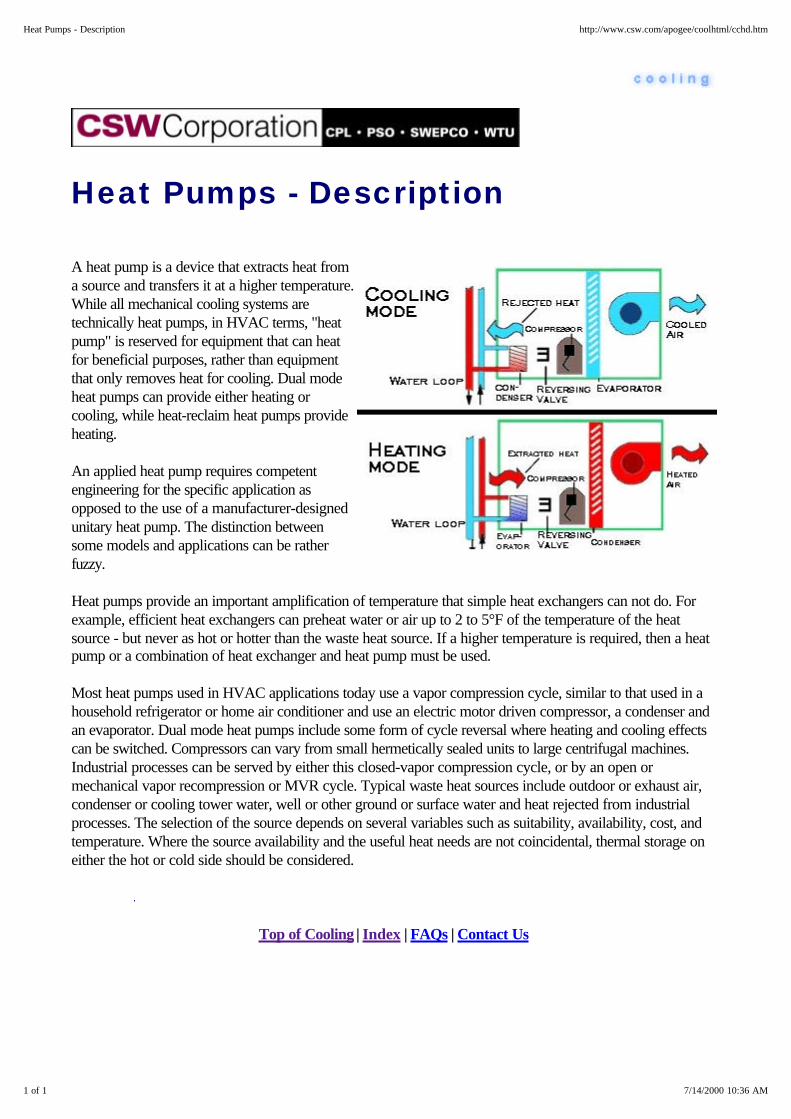
Heat Pumps - Description
A heat pump is a device that extracts heat froma source and transfers it at a higher temperature.While all mechanical cooling systems aretechnically heat pumps, in HVAC terms, "heatpump" is reserved for equipment that can heatfor beneficial purposes, rather than equipmentthat only removes heat for cooling. Dual modeheat pumps can provide either heating orcooling, while heat-reclaim heat pumps provideheating.
An applied heat pump requires competentengineering for the specific application asopposed to the use of a manufacturer-designedunitary heat pump. The distinction betweensome models and applications can be ratherfuzzy.
Heat pumps provide an important amplification of temperature that simple heat exchangers can not do. Forexample, efficient heat exchangers can preheat water or air up to 2 to 5°F of the temperature of the heatsource - but never as hot or hotter than the waste heat source. If a higher temperature is required, then a heatpump or a combination of heat exchanger and heat pump must be used.
Most heat pumps used in HVAC applications today use a vapor compression cycle, similar to that used in ahousehold refrigerator or home air conditioner and use an electric motor driven compressor, a condenser andan evaporator. Dual mode heat pumps include some form of cycle reversal where heating and cooling effectscan be switched. Compressors can vary from small hermetically sealed units to large centrifugal machines.Industrial processes can be served by either this closed-vapor compression cycle, or by an open ormechanical vapor recompression or MVR cycle. Typical waste heat sources include outdoor or exhaust air,condenser or cooling tower water, well or other ground or surface water and heat rejected from industrialprocesses. The selection of the source depends on several variables such as suitability, availability, cost, andtemperature. Where the source availability and the useful heat needs are not coincidental, thermal storage oneither the hot or cold side should be considered.
Top of Cooling | Index | FAQs | Contact Us
1 of 1 7/14/2000 10:36 AM
Heat Pumps - Description http://www.csw.com/apogee/coolhtml/cchd.htm
Heat Pumps - Unitary Heat Pumps
Unitary heat pumps are factory-packaged refrigerant-based heat pumps that are available in a number ofapplication categories which include:
Packaged terminal heat pumps (PTHP) Closed water loop heat pump systems Ground source closed-loop heat pumps Ground water-source heat pumps Large unitary air- and water-source heat pumps In each category there are several possible configurations, including: Single package, with all components in a single enclosure Roof-top packages - a variation on the single package Split units, with remote outdoor coil, fan, and/or compressor Air and water-source heat pumps Heating only heat pumps Package units and the indoor sections of split units are available in several configurations: Vertical for closet installations, Console for installation under windows, and Horizontal for ceiling or outdoor locations.
Some models have decorative casings. Others can be built-in. With the exception of large unitary heat pumps,the units are designed for free-air delivery or with short duct connections between the unit and the conditionedspace.
Most heat pump manufacturers participate in the Air-Conditioning and Refrigeration Institute (ARI)Certification Program. Product performance (below 135,000 Btuh sizes) is listed in the ARI Directory ofCertified Products. This allows a performance comparison of various models from various manufacturers.
Sizes range from l/2-ton package terminal heat pumps up to rooftop units of 30-tons or more. Many areprovided with supplemental electric heaters to satisfy the load when the outdoor temperatures drop below theset point. Gas fired supplemental heat is also available in a limited range of equipment. Most heat pumps aresold and installed by local air conditioning contractors, who also provide routine service and repair. Dependingon the nature of the application, this availability of fast service can be very important in equipment selection.
Select from these areas of interest . . .
Advantages of Unitary Heat Pumps Advantages of Water-Loop Heat Pumps
Disadvantages of Water-Loop Heat Pumps Unitary Air and Water Heat Pumps
1 of 2 7/14/2000 10:37 AM
Heat Pumps - Unitary Heat Pumps http://www.csw.com/apogee/coolhtml/cxchu.htm

Advantages of Unitary Heat Pumps
1. They provide individual temperature control in small occupied zones during nights and weekends without theneed for a large central plant chiller or boiler and their associated pumps, and
2. The heat pump's consumption of electricity can be separately metered.
Top of Cooling | Index | FAQs | Contact Us
1 of 1 7/14/2000 10:42 AM
Advantages of Unitary Heat Pumps http://www.csw.com/apogee/coolhtml/cchuu.htm

Advantages of Water-loop HeatPumps
1. They don't require wall openings to reject heat from air-cooled condensers,
2. They aren't exposed to the weather and therefore tend to have a longer service life,
3. If a unit fails, the entire system doesn't shut down, however, failure of a loop pump, heat rejection device orsecondary heater can affect the entire system.
Top of Cooling | Index | FAQs | Contact Us
1 of 1 7/14/2000 10:41 AM
Advantages of Water-loop Heat Pumps http://www.csw.com/apogee/coolhtml/cchuw.htm
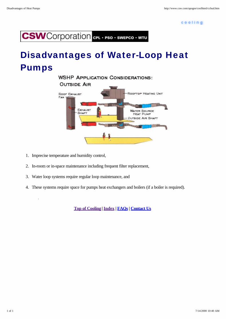
Disadvantages of Water-Loop HeatPumps
1. Imprecise temperature and humidity control,
2. In-room or in-space maintenance including frequent filter replacement,
3. Water loop systems require regular loop maintenance, and
4. These systems require space for pumps heat exchangers and boilers (if a boiler is required).
Top of Cooling | Index | FAQs | Contact Us
1 of 1 7/14/2000 10:40 AM
Disadvantages of Heat Pumps http://www.csw.com/apogee/coolhtml/cchud.htm
Unitary Air and Water Heat Pumps
Unitary air and water source heat pumps are available as larger capacity commercial self-contained units whichserve large zones using ducts for air distribution. Air-source units must be located along outside walls or on theroof. They tend to have higher operating costs than central plants or water-source heat pumps.
Water-source units can be located anywhere but require ventilation air ducts. They are usuallyconnected to a cooling tower circuit for heat rejection when they are in the cooling mode, and to acentral hot-water heater or strip heater when heating is required. Advantages include low first cost andthe availability of optional accessories (variable air volume control, economizer cycle, night setback andmorning warm-up).
Large system heat pump applications are often applied in, buildings using two- or four-pipe waterdistribution systems, or in industrial applications. Many large buildings require cooling the year-rounddue to large internal loads from lighting, electronic and other business equipment. Only the perimeterzones of these structures ever need heating. The warm condenser water from the water chillers servingthis cooling load can be used as a heat source. The water-to-water heat pump is piped in a cascadesystem, using this waste heat to preheat domestic hot water or provide hot water to satisfy buildingspace or reheat loads. Units are available to heat water from 105°F to 120°F, or even higher if needed.The lower the hot water temperature required, the lower the energy consumption.
In some cases, the units are combined into a single heat recovery chiller with a double-bundle condenser. Thehouse water condenser serves the hot water loop for the building. When the waste heat exceeds the heatrequirement, the excess heat is rejected in the second tower water condenser. Thermal storage can also beintegrated into this system. Other options include integration with closed loop water-to-air heat pumps, orsecondary heat recovery from water loop heat pump systems.
Air-to-water heat pumps perform in a similar manner but typically use warm exhaust air as the heatsource. They are often referred to as heat pump water heaters and are used in hotels, restaurants,laundries and other applications needing a lot of hot water.
Many industrial processes have low-level waste heat that must be rejected. Factory-packaged, closed-cyclerefrigerant-based heat pumps are available to heat water to 120°F or warmer. Using waste heat for thispurpose off-loads cooling towers or evaporative condensers while reducing boiler fuel consumption and thecorresponding products of combustion.
Top of Cooling | Index | FAQs | Contact Us
1 of 1 7/14/2000 10:42 AM
Unitary Air and Water Heat Pumps http://www.csw.com/apogee/coolhtml/cchua.htm

Top of Cooling | Index | FAQs | Contact Us
2 of 2 7/14/2000 10:37 AM
Heat Pumps - Unitary Heat Pumps http://www.csw.com/apogee/coolhtml/cxchu.htm
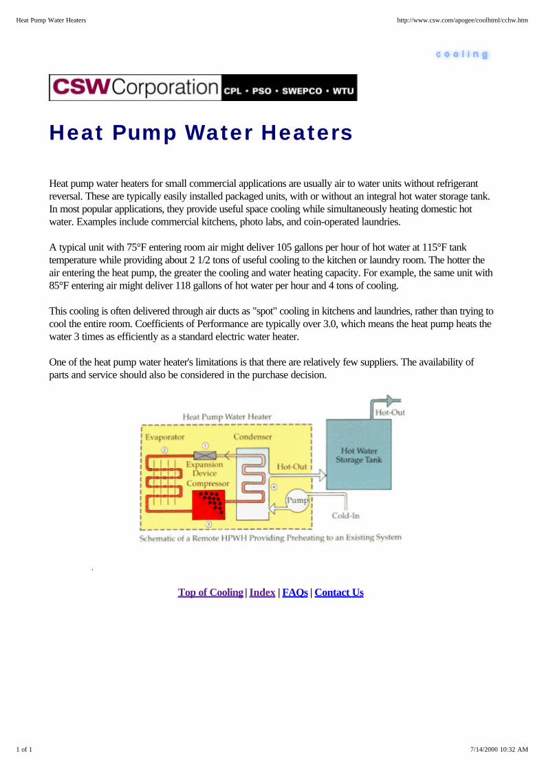
Heat Pump Water Heaters
Heat pump water heaters for small commercial applications are usually air to water units without refrigerantreversal. These are typically easily installed packaged units, with or without an integral hot water storage tank.In most popular applications, they provide useful space cooling while simultaneously heating domestic hotwater. Examples include commercial kitchens, photo labs, and coin-operated laundries.
A typical unit with 75°F entering room air might deliver 105 gallons per hour of hot water at 115°F tanktemperature while providing about 2 1/2 tons of useful cooling to the kitchen or laundry room. The hotter theair entering the heat pump, the greater the cooling and water heating capacity. For example, the same unit with85°F entering air might deliver 118 gallons of hot water per hour and 4 tons of cooling.
This cooling is often delivered through air ducts as "spot" cooling in kitchens and laundries, rather than trying tocool the entire room. Coefficients of Performance are typically over 3.0, which means the heat pump heats thewater 3 times as efficiently as a standard electric water heater.
One of the heat pump water heater's limitations is that there are relatively few suppliers. The availability ofparts and service should also be considered in the purchase decision.
Top of Cooling | Index | FAQs | Contact Us
1 of 1 7/14/2000 10:32 AM
Heat Pump Water Heaters http://www.csw.com/apogee/coolhtml/cchw.htm
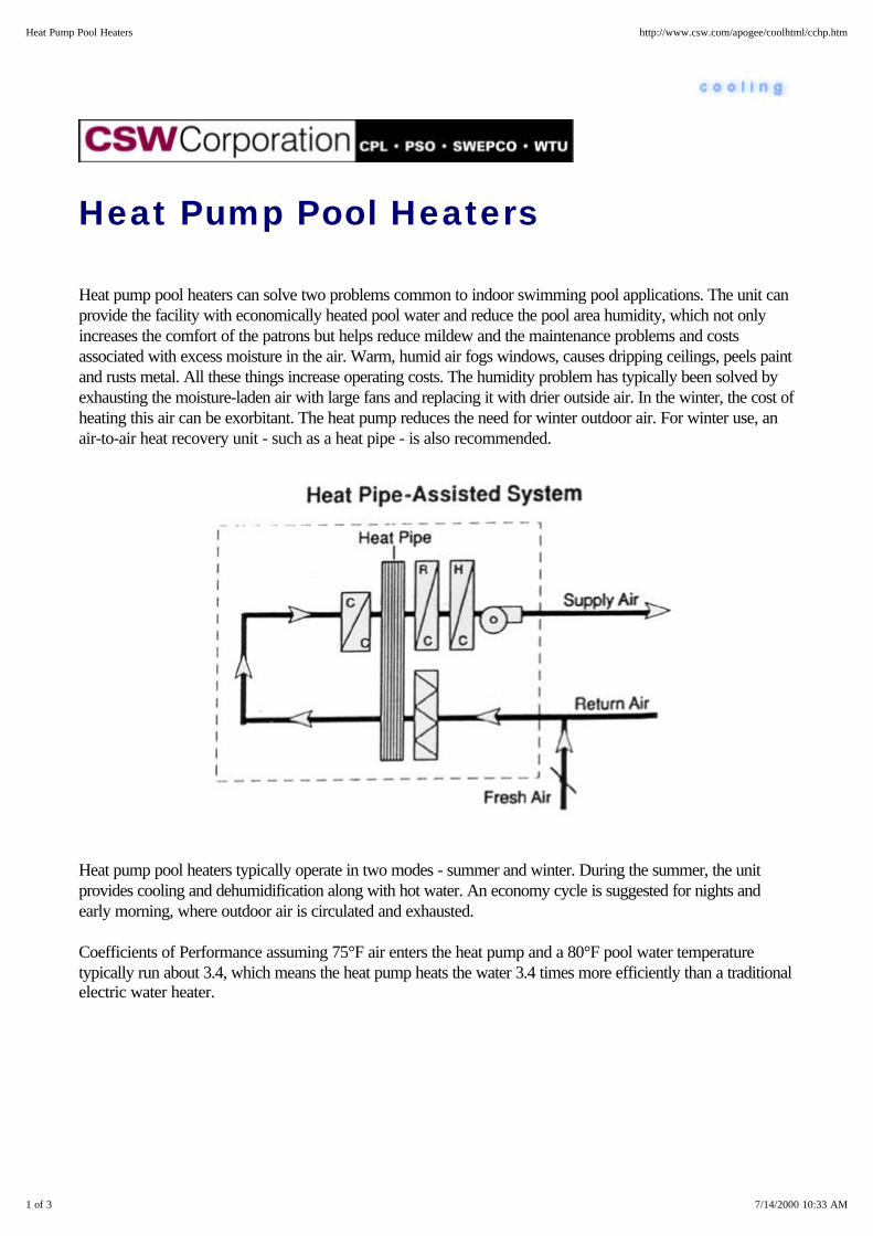
Heat Pump Pool Heaters
Heat pump pool heaters can solve two problems common to indoor swimming pool applications. The unit canprovide the facility with economically heated pool water and reduce the pool area humidity, which not onlyincreases the comfort of the patrons but helps reduce mildew and the maintenance problems and costsassociated with excess moisture in the air. Warm, humid air fogs windows, causes dripping ceilings, peels paintand rusts metal. All these things increase operating costs. The humidity problem has typically been solved byexhausting the moisture-laden air with large fans and replacing it with drier outside air. In the winter, the cost ofheating this air can be exorbitant. The heat pump reduces the need for winter outdoor air. For winter use, anair-to-air heat recovery unit - such as a heat pipe - is also recommended.
Heat pump pool heaters typically operate in two modes - summer and winter. During the summer, the unitprovides cooling and dehumidification along with hot water. An economy cycle is suggested for nights andearly morning, where outdoor air is circulated and exhausted.
Coefficients of Performance assuming 75°F air enters the heat pump and a 80°F pool water temperaturetypically run about 3.4, which means the heat pump heats the water 3.4 times more efficiently than a traditionalelectric water heater.
1 of 3 7/14/2000 10:33 AM
Heat Pump Pool Heaters http://www.csw.com/apogee/coolhtml/cchp.htm
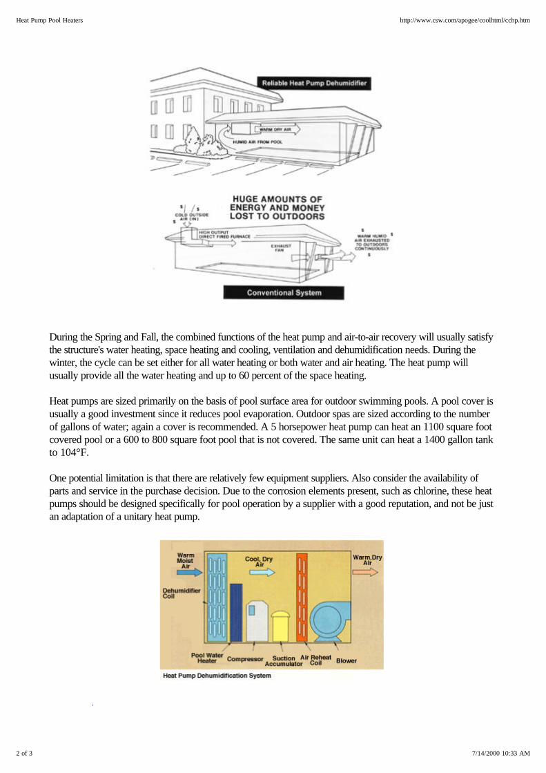
During the Spring and Fall, the combined functions of the heat pump and air-to-air recovery will usually satisfythe structure's water heating, space heating and cooling, ventilation and dehumidification needs. During thewinter, the cycle can be set either for all water heating or both water and air heating. The heat pump willusually provide all the water heating and up to 60 percent of the space heating.
Heat pumps are sized primarily on the basis of pool surface area for outdoor swimming pools. A pool cover isusually a good investment since it reduces pool evaporation. Outdoor spas are sized according to the numberof gallons of water; again a cover is recommended. A 5 horsepower heat pump can heat an 1100 square footcovered pool or a 600 to 800 square foot pool that is not covered. The same unit can heat a 1400 gallon tankto 104°F.
One potential limitation is that there are relatively few equipment suppliers. Also consider the availability ofparts and service in the purchase decision. Due to the corrosion elements present, such as chlorine, these heatpumps should be designed specifically for pool operation by a supplier with a good reputation, and not be justan adaptation of a unitary heat pump.
2 of 3 7/14/2000 10:33 AM
Heat Pump Pool Heaters http://www.csw.com/apogee/coolhtml/cchp.htm

Top of Cooling | Index | FAQs | Contact Us
3 of 3 7/14/2000 10:33 AM
Heat Pump Pool Heaters http://www.csw.com/apogee/coolhtml/cchp.htm

Packaged Terminal Heat Pumps(PTHP)
Packaged terminal heat pumps (PTHP) are very much like a high quality version of the window-mounted airconditioner with the heat pump accessories added. These models are often called "through the-wall" units sincethey are usually installed in a sleeve passing through the outdoor building wall. PTHPs are completely selfcontained, requiring only a permanent electrical connection. They use the outdoor air as the heat source inwinter and as a heat sink in summer. They also can provide ventilation air. Individual control is typical withauxiliary electric resistance strip heat and central control features as added-cost, site-specific options.
Flexibility and lower installed cost are the primary advantages of the PTHP. Disadvantages include in-roommaintenance, higher operating cost, relatively short life, imprecise "on-off" temperature control, and they can berather noisy.
Top of Cooling | Index | FAQs | Contact Us
1 of 1 7/14/2000 10:45 AM
Packaged Terminal Heat Pumps (PTHP) http://www.csw.com/apogee/coolhtml/ccht.htm
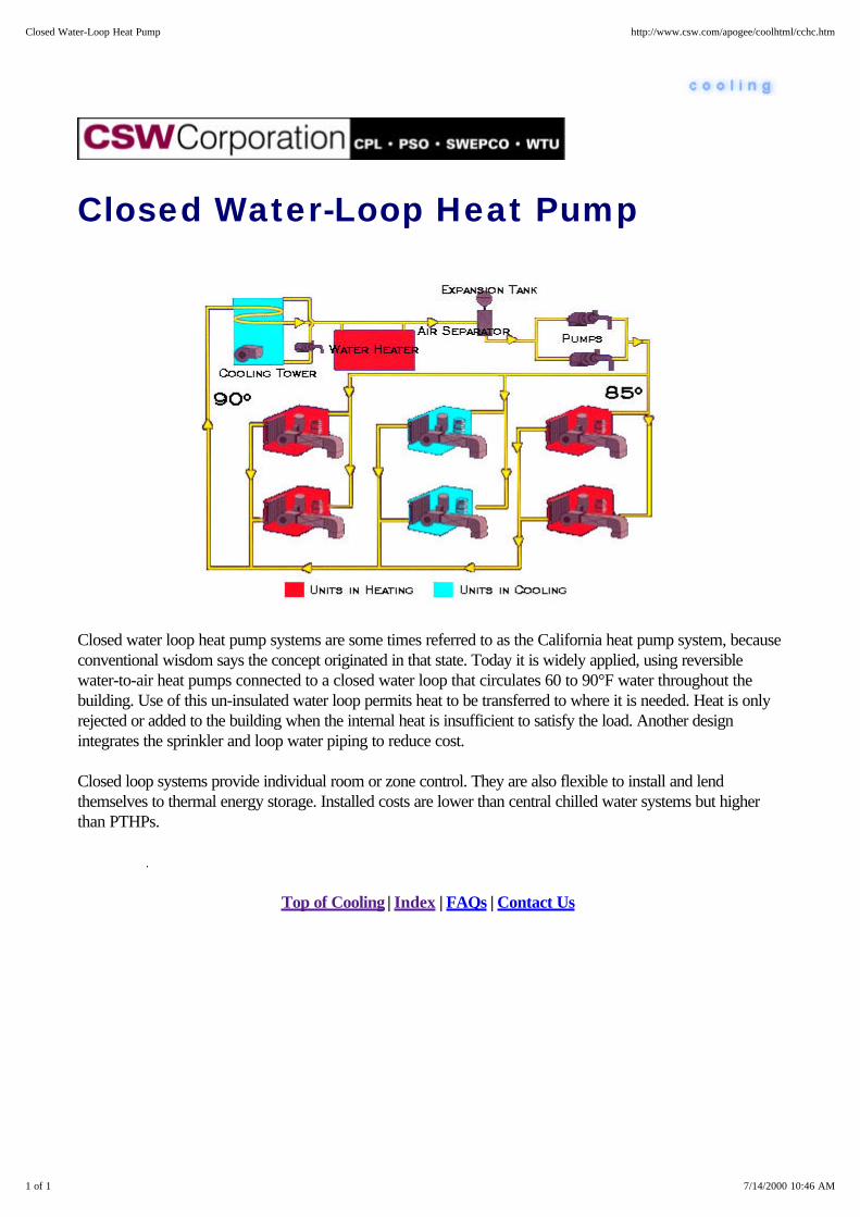
Closed Water-Loop Heat Pump
Closed water loop heat pump systems are some times referred to as the California heat pump system, becauseconventional wisdom says the concept originated in that state. Today it is widely applied, using reversiblewater-to-air heat pumps connected to a closed water loop that circulates 60 to 90°F water throughout thebuilding. Use of this un-insulated water loop permits heat to be transferred to where it is needed. Heat is onlyrejected or added to the building when the internal heat is insufficient to satisfy the load. Another designintegrates the sprinkler and loop water piping to reduce cost.
Closed loop systems provide individual room or zone control. They are also flexible to install and lendthemselves to thermal energy storage. Installed costs are lower than central chilled water systems but higherthan PTHPs.
Top of Cooling | Index | FAQs | Contact Us
1 of 1 7/14/2000 10:46 AM
Closed Water-Loop Heat Pump http://www.csw.com/apogee/coolhtml/cchc.htm

Ground Water-Source Heat Pump
Ground water-source heat pump systemstake advantage of the fact that thetemperature of the earth near the surfaceis around 55°F year-round. Water froman aquifer is typically in this range. Insome locations, it is considerably higher.This water tends to be a better source ofheat for the heat pump than outdoor air.These systems can also use surface water(such as lakes, rivers, ponds, and so on).In these cases, ground or surface water iscirculated directly through the unit orthrough a main heat exchanger.
Top of Cooling | Index | FAQs | Contact Us
1 of 1 7/14/2000 10:46 AM
Ground Water-Source Heat Pump http://www.csw.com/apogee/coolhtml/cchg.htm

Heat Pumps - Open Loop Systems In open loop systems, the water is taken from an aquifer or othersource, circulated and then discharged to another well or stream. Themain disadvantages of this type of system are associated with waterquality and corrosion, and the regulations regarding water use. Theadvantages include individual room or zone control and flexibility ininstallation. Installed costs are lower than central chilled water systemsbut higher than with closed loop heat pumps, or air-to-air systems,largely due to the cost of the ground-water source.
Top of Cooling | Index | FAQs | Contact Us
1 of 1 7/14/2000 10:47 AM
Heat Pumps - Open Loop Systems http://www.csw.com/apogee/coolhtml/ccho.htm
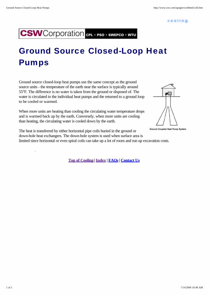
Ground Source Closed-Loop HeatPumps
Ground source closed-loop heat pumps use the same concept as the groundsource units - the temperature of the earth near the surface is typically around55°F. The difference is no water is taken from the ground or disposed of. Thewater is circulated to the individual heat pumps and the returned to a ground loopto be cooled or warmed.
When more units are heating than cooling the circulating water temperature dropsand is warmed back up by the earth. Conversely, when more units are coolingthan heating, the circulating water is cooled down by the earth.
The heat is transferred by either horizontal pipe coils buried in the ground ordown-hole heat exchangers. The down-hole system is used when surface area islimited since horizontal or even spiral coils can take up a lot of room and run up excavation costs.
Top of Cooling | Index | FAQs | Contact Us
1 of 1 7/14/2000 10:48 AM
Ground Source Closed-Loop Heat Pumps http://www.csw.com/apogee/coolhtml/cchl.htm
Low Temp Air
Low temperature primary air systems provide 42°F to 48°F supply air for comfort cooling. The principaladvantages of this air delivery option over conventional systems include lower first cost, lower electricaldemand and reduced operating costs.
The smaller fans and ductwork diameters required for low temperature air systems not only reduce equipmentcosts, but also offer the potential for architectural savings, since less floor-to-floor height is needed. Andbecause the fans and pumps used require less horsepower, the system consumes less energy than manytraditional types of air delivery.
Low temperature supply air also improves comfort levels by reducing the relative humidity in the occupiedspace. This reduction in humidity often results in a perceived improvement in indoor air quality. In addition,occupants tend to desire warmer space temperatures which can lead to additional energy savings. Typicalroom conditions for a low temperature primary air system are 78°F with a relative humidity of 35 to 45percent.
And Furthermore . . .
Low Temp Air - Application Considerations
Top of Cooling | Index | FAQs | Contact Us
1 of 1 7/14/2000 10:54 AM
Low Temp Air http://www.csw.com/apogee/coolhtml/cxco.htm

Low Temp Air - ApplicationConsiderations
Proper care must be taken to ensure that condensate does not develop on the ductwork or terminal units.Selection of air diffusers is of particular importance to ensure adequate distribution at lower airflow volumes.And, particular care must be taken to assure required air changes for adequate ventilation (i.e., outside air atmodulated conditions), as well as for smoke pressurization strategies.
Top of Cooling | Index | FAQs | Contact Us
1 of 1 7/14/2000 10:54 AM
Low Temp Air - Application Considerations http://www.csw.com/apogee/coolhtml/ccoa.htm
Thermal Storage
Thermal storage is a method of producing thermal energy when it is not needed (or is less expensive toproduce) so it will be available when it is needed (or is more expensive to produce). Chilled water, iceharvesters, ice-on-pipe and glycol systems are all used for transporting heat and storing cooling effect.
Select from these areas of interest . . .
Chilled Water Ice-On-Pipe
Ice Harvesters Glycol Systems
Top of Cooling | Index | FAQs | Contact Us
1 of 1 7/14/2000 10:55 AM
Thermal Storage http://www.csw.com/apogee/coolhtml/cxct.htm

Thermal Storage - Chilled Water
A chilled water thermal storage system uses the sensible heat in a body of water to store BTUs. Simply put,water passing through a chilled water coil warms as it absorbs BTUs from and subsequently cools thesurrounding air. Given its specific heat of 1 Btu/lb F, about 10 cu ft of water are required to absorb 12,000BTUs and provide 1 ton-hour of cooling if the coil successfully raises the water temperature by 20°F.
By contrast, the same ton-hour of cooling can be provided with just 1.5 cu ft of ice, since each pound of iceabsorbs 144 BTUs as it melts. Therefore, a thermal storage system that uses chilled water rather than ice willrequire 6 to 7 times more installed storage volume.
This graph plots the cost of thermal storage components as a function of the ton-hours of cooling stored. Thesizable cost penalty imposed by the significantly larger storage tank volume required for chilled water is readilyapparent in a cost-line comparison with ice storage. Keep in mind, however, that the cost of the water storagetank is a function of its surface area, while the capacity of the tank is a function of its volume. Therefore, as asystem requires very large chilled water storage tanks, the per-ton-hour cost of the storage tank actuallydecreases. Consequently, it appears that chilled water may be competitive with ice in applications that requiremore than 10,000 ton-hours of thermal storage.
1 of 2 7/14/2000 11:03 AM
Thermal Storage - Chilled Water http://www.csw.com/apogee/coolhtml/cxctw.htm

A chilled water storage system is really just a simple variation of a decoupled chiller system. Since the samefluid water is used to both store and transfer heat, very few accessories must be added to the system. Thisgives chilled water storage its principle advantage: It's easy to put in place.
As shown in this schematic, a decoupled system separates the production and distribution of chilled water. Thebalance of flow between the constant volume production of chilled water and its variable volume distribution ishandled with a bypass pipe commonly called a "decoupler." The decoupler bypasses surplus chilled waterwhen production exceeds distribution and borrows return water when distribution exceeds supply. In effect,the decoupler pipe itself can serve as a chilled water storage tank if its volume is large enough.
Select from these areas of interest . . .
Series Storage Tanks Parallel Storage Tanks
Stratified Storage Tanks Pros and Cons
Top of Cooling | Index | FAQs | Contact Us
2 of 2 7/14/2000 11:03 AM
Thermal Storage - Chilled Water http://www.csw.com/apogee/coolhtml/cxctw.htm

Thermal Storage - Chilled Water -Series Storage Tanks
The simplest form of chilled water storage places one or more tanks in series in the decoupler line. This isshown in this single baffled tank. Now, when the chillers produce more chilled water than the system requires,the excess is diverted to the series tank where it displaces the warmer water there. Likewise, when chilledwater demand exceeds the quantity produced, chilled water is drawn from the storage tank by displacing itwith warm return water.
A number of chilled water storage systems with designs similar to this have been installed and have proven tobe fairly effective in reducing on-peak electrical demand. However, series tank design can cause the water tostratify or become stagnant. Stagnation is the tendency of water to shortcut its way through the tank, andrenders large volumes of the tank ineffective for Btu storage. Furthermore, intercompartmental mixing raises thetank's leaving water temperature as it empties. This reduces tank effectiveness during its final hours ofdischarge.
Top of Cooling | Index | FAQs | Contact Us
1 of 1 7/14/2000 11:06 AM
Thermal Storage - Chilled Water - Series Storage Tanks http://www.csw.com/apogee/coolhtml/cctws.htm
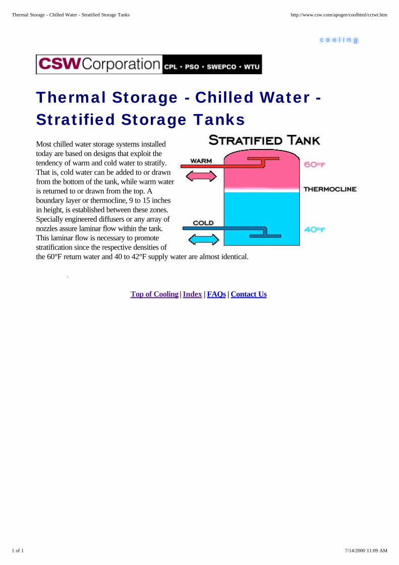
Thermal Storage - Chilled Water -Stratified Storage Tanks Most chilled water storage systems installedtoday are based on designs that exploit thetendency of warm and cold water to stratify.That is, cold water can be added to or drawnfrom the bottom of the tank, while warm wateris returned to or drawn from the top. Aboundary layer or thermocline, 9 to 15 inchesin height, is established between these zones.Specially engineered diffusers or any array ofnozzles assure laminar flow within the tank.This laminar flow is necessary to promotestratification since the respective densities ofthe 60°F return water and 40 to 42°F supply water are almost identical.
Top of Cooling | Index | FAQs | Contact Us
1 of 1 7/14/2000 11:09 AM
Thermal Storage - Chilled Water - Stratified Storage Tanks http://www.csw.com/apogee/coolhtml/cctwt.htm

Thermal Storage - Chilled Water -Pros and Cons
Chilled water thermal storage systems offer a number of attractive benefits. Because of the decreasing unit costof the tanks, chilled water storage can be economically attractive in larger systems. These systems also allowthe chiller to operate at peak efficiency during the storage cycle. And, since the storage medium chilled is thesame fluid that is cooled in the chiller and warmed in the cooling coil, few accessories are required. Note aswell, that storing a large volume of water on site can be a valuable asset for fire/life safety systems. In fact,some system designs use sprinkler system water in their design.
Of course, the disadvantages of chilled water storage - most of which relate to the tank - must also berecognized. The storage tank's design, weight, location and space requirements can pose some unusualproblems...along with tank leakage. In addition, storage tank costs can vary significantly because the tank isconstructed on site. And, don't forget water treatment cost. The water stored is used in the chilled watersystem as well.
Perhaps the most significant problem with chilled water as a storage medium is inherent to the chilled watersystem itself. To be effective, chilled water storage systems must raise the return water temperature torelatively high values. If the chilled water distribution system cannot achieve this, the Btu storage capacity of thetank is severely impaired. Continual monitoring and disciplined maintenance of the chilled water valves andcontrollers are required to assure that chilled water always returns to the tank at the warmest possibletemperature.
The chilled water thermal storage system's installed cost curve shows the significance of storage tank expense.While somewhat prohibitive for most applications under l0,000 ton-hours, the decreasing unit cost of chilledwater storage systems can be very attractive for large central plants and industrial installations.
1 of 2 7/14/2000 11:08 AM
Thermal Storage - Chilled Water - Pros and Cons http://www.csw.com/apogee/coolhtml/cctwc.htm
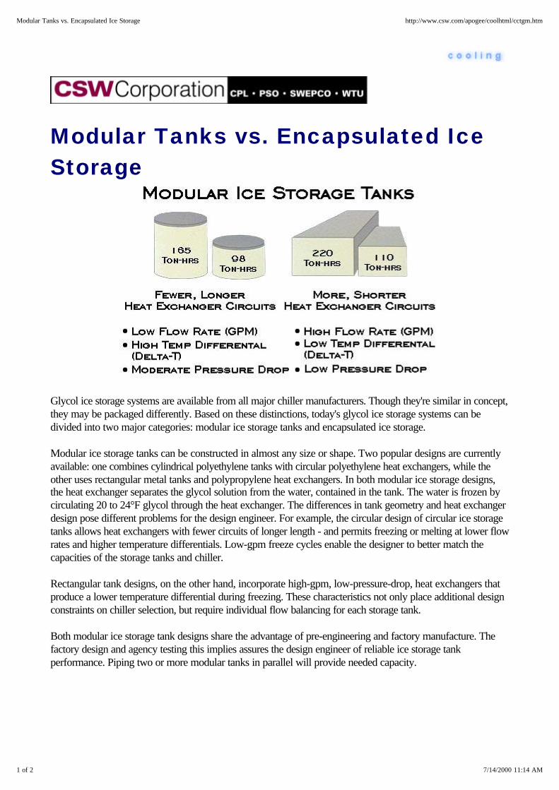
Modular Tanks vs. Encapsulated IceStorage
Glycol ice storage systems are available from all major chiller manufacturers. Though they're similar in concept,they may be packaged differently. Based on these distinctions, today's glycol ice storage systems can bedivided into two major categories: modular ice storage tanks and encapsulated ice storage.
Modular ice storage tanks can be constructed in almost any size or shape. Two popular designs are currentlyavailable: one combines cylindrical polyethylene tanks with circular polyethylene heat exchangers, while theother uses rectangular metal tanks and polypropylene heat exchangers. In both modular ice storage designs,the heat exchanger separates the glycol solution from the water, contained in the tank. The water is frozen bycirculating 20 to 24°F glycol through the heat exchanger. The differences in tank geometry and heat exchangerdesign pose different problems for the design engineer. For example, the circular design of circular ice storagetanks allows heat exchangers with fewer circuits of longer length - and permits freezing or melting at lower flowrates and higher temperature differentials. Low-gpm freeze cycles enable the designer to better match thecapacities of the storage tanks and chiller.
Rectangular tank designs, on the other hand, incorporate high-gpm, low-pressure-drop, heat exchangers thatproduce a lower temperature differential during freezing. These characteristics not only place additional designconstraints on chiller selection, but require individual flow balancing for each storage tank.
Both modular ice storage tank designs share the advantage of pre-engineering and factory manufacture. Thefactory design and agency testing this implies assures the design engineer of reliable ice storage tankperformance. Piping two or more modular tanks in parallel will provide needed capacity.
1 of 2 7/14/2000 11:14 AM
Modular Tanks vs. Encapsulated Ice Storage http://www.csw.com/apogee/coolhtml/cctgm.htm

The other class of glycol systems, encapsulated ice, offers the system designer an even greater degree oflatitude in the design of the ice containment vessel. Various construction materials and geometries that willconform to available space and building architecture can be exploited.
Encapsulated ice designs store the water to be frozen in a number of plastic containers. These containers maybe flat and rectangular (shaped somewhat like a giant hot water bottle), spherical, or annular ("doughnut"shaped). The number of containers or units required for an application depends on their individual storagecapacity. For example, one ton-hour of storage can be provided with approximately 20 of the ice trays or by70 of the four-inch diameter spheres, called "ice balls". Other internationally manufactured designs are alsoavailable.
Perhaps the greatest advantage of this type of glycol system is the degree of application flexibility it affords thesystem designer. By selecting and designing a specifically adapted containment vessel, the storage system cango above grade or below ground.
Although glycol ice storage systems presently enjoy a great deal of market popularity because of theirsimplicity and low installed cost, the system designer can choose from a wide variety of thermal storagetechnologies and equipment.
Top of Cooling | Index | FAQs | Contact Us
2 of 2 7/14/2000 11:14 AM
Modular Tanks vs. Encapsulated Ice Storage http://www.csw.com/apogee/coolhtml/cctgm.htm

Thermal Storage - Ice-On-Pipe
Ice on pipe thermal storage designs produce ice by pumping very cold liquid refrigerant (usually HCFC-22 incommercial applications or ammonia in industrial refrigeration applications) through on array of pipes immersedin a tank of water.
Technically, ice-on-pipe thermal storage is process refrigeration. System components - i.e., the compressorand condenser(s), high and low-pressure receivers, refrigerant pumps, evaporators and ice tanks - areindividually selected for the application, but must perform together in a reliable refrigeration system. Thedesigner has wide latitude in component selection and may customize the system with a variety of accessories.Of course, this means the designer must assume total responsibility for system performance and reliability!
Unlike direct expansion systems, which rely on additional heat transfer surface area to separate refrigerantvapor from liquid refrigerant, ice-on-pipe systems use a low-pressure receiver and a method called liquidoverfeed to accomplish this.
1 of 3 7/14/2000 10:58 AM
Thermal Storage - Ice-On-Pipe http://www.csw.com/apogee/coolhtml/cxctp.htm

A liquid overfeed system works like this. Chilled water and/or ice is produced by pumping cold liquidrefrigerant to a chiller evaporator or an ice tank at a rate 1.3 to 1.6 times faster than it can be evaporatedthere. What results is a "two-phase" solution of refrigerant liquid and vapor that is returned to the low-pressurereceiver. This 30-60% higher refrigerant flow is why the system gets the name liquid overfeed.
The refrigerant returned to the low-pressure receiver is quite saturated, so no additional evaporator heattransfer surface is lost in the task of performing superheat. Refrigerant liquid that does not "boil off" in theevaporator is sent back for a second pass.
Notice that the open or "atmospheric" design of an ice-on-pipe system dictates the use of a heat exchanger toseparate ice water from the building cooling water loop. (The cooling loop is normally a closed system).
Here, on the high-pressure side of the system, the cold refrigerant vapor that collects at the top of thelow-pressure receiver is drawn off by the compressor. From the compressor, the pressurized (and now hot)vapor is sent to the condenser, where cooling tower water circulating through the shell causes the refrigerant tocondense. The liquid refrigerant, still under high pressure, leaves the condenser and passes to a high-pressurereceiver where it is stored for later use. Refrigerant flow from the high-pressure receiver is regulated by arefrigerant metering device to assure that a minimum liquid level is maintained in the low-pressure receiver.
The ice produced by an ice-on-pipe system forms on the exterior surfaces of an "ice coil." This coil is actuallya series of steel pipes immersed in a tank of water. Cold refrigerant (usually HCFC-22) is then pumpedthrough these pipes to freeze the water that surrounds them.
The bubbles around the steel pipes agitate the water in the tank - sometimes by injecting air at the bottom -which is important. The rising air bubbles promote dense, even ice formation during the freezing cycle anduniform melting when the tank is discharged.
As suggested earlier, the low-pressure receiver plays a critical role in liquid overfeed ice-on-pipe systems: itseparates the two-phase refrigerant solution returning from the ice coil (or chiller evaporator) into liquid andvapor. Gravity induces this separation, causing the liquid refrigerant and oil to settle to the bottom of thereceiver while pure refrigerant vapor collects at the top. As the compressor draws this vapor from the receiver,the liquid level falls. To assure that there is always sufficient liquid in this vessel, a liquid level control addsrefrigerant from the high-pressure receiver as needed.
While only hinted at here, liquid overfeed systems require a separate oil return/recovery system. This isbecause the preferred compressor type - helical rotary/screw - expels significant amounts of oil into thedischarge line. Entrained in the refrigerant, the oil makes its way through the condenser and high pressurereceiver, eventually ending up in the low-pressure receiver. There, the oil collects at the bottom of the tank(along with the liquid refrigerant) and cannot return to the compressor through the suction line. A separate oilrecovery system is needed to capture, distill and return the oil to the compressor. This must be carefullyaddressed in the system design.
2 of 3 7/14/2000 10:58 AM
Thermal Storage - Ice-On-Pipe http://www.csw.com/apogee/coolhtml/cxctp.htm

The complexity of the liquid overfeed ice-on-pipe system translates into significant fixed costs that areindependent of the quantity of ice produced and stored. The refrigerant and oil inventory control systems,refrigerant pumps and other system accessories plus the field labor required to install them constitute a sizableinvestment.
Depending on the system's size, the tank can be either premanufactured to include both the ice coil and tank,or field-assembled by installing the ice coil in a field-erected concrete tank. While this makes the per-ton-hourcost of the tank attractive, it only partially offsets the combined cost of field labor and accessories, even whenthe lower compressor cost is considered. The high costs of engineering and installing liquid overfeedice-on-pipe systems typically limit their use to larger applications.
And Furthermore . . .
Thermal Storage - Ice-On-Pipe Pros and Cons
Top of Cooling | Index | FAQs | Contact Us
3 of 3 7/14/2000 10:58 AM
Thermal Storage - Ice-On-Pipe http://www.csw.com/apogee/coolhtml/cxctp.htm

Thermal Storage - Ice Harvesters
Ice harvesters circumvent the problems associated with liquid overfeed ice-on-pipe systems by combining allof the components and accessories required for ice production in a single manufactured package. This piece ofequipment, called an ice harvester, is installed above an open tank that stores a combination of water andflakes of ice.
To produce ice, 32°F water is drawn from the storage tank and delivered to the ice harvester by arecirculation pump at a flow rate of 8 to 12 gallons per minute per ton of ice-producing capacity. Once insidethe ice harvester, the recirculated water flows into a drain pan positioned over a series of refrigerated plates.Each of these plates is constructed of two stainless steel sheets welded together at their circumference. Arefrigeration system integral to the ice harvester maintains the plates at a temperature of 15 to 20°F.
As the water leaves the drain pan, it flows freely over both sides of the refrigerated plates where it freezes to athickness of 1/8 to 3/8 inch. On reaching a given thickness - or at the initiation of a time clock - the ice isdislodged from the plates by a hot gas defrost cycle, and falls into the tank below. When cooling is required, atransfer pump draws ice water from the storage tank and delivers it to a building heat exchanger.
It is possible to use the ice harvester as a water chiller by raising the suction temperature of the refrigerationsystem and pumping warm water from the building heat exchanger over the refrigerated plates. In fact,operating at this higher suction temperature improves the ice harvester's efficiency. Unfortunately, the iceharvester cannot produce chilled water without destroying ice stored in the storage tank. This inability tooperate as a true water chiller in a chilled water system poses a significant efficiency penalty on ice storagesystems with ice harvesters. To get around this inefficiency, ice harvesters are commonly used in tandem withconventional water chillers.
Select from these areas of interest . . .
Ice Harvesters - Cost Ice Harvesters - Advantages
1 of 2 7/14/2000 10:57 AM
Thermal Storage - Ice Harvesters http://www.csw.com/apogee/coolhtml/cxcth.htm

Ice Harvesters - Disadvantages
Top of Cooling | Index | FAQs | Contact Us
2 of 2 7/14/2000 10:57 AM
Thermal Storage - Ice Harvesters http://www.csw.com/apogee/coolhtml/cxcth.htm
Thermal Storage - Ice-On-Pipe Prosand Cons
Ice-on-pipe systems offer a number of benefits over chilled water storage. The storage volume required isconsiderably less, since each ton-hour of cooling stored can occupy as little as 3 cu ft. Another advantage isthe ice tank's known thermal performance. And, unlike their chilled water counterparts, ice storage systems aresuccessful at any return water temperature.
An effective ice-on-pipe system must overcome several engineering problems. Foremost among these is thesystem's complexity and the correspondingly high costs that must be incurred for engineering and installation.Liquid overfeed ice-on-pipe systems are particularly expensive because they require not only large inventoriesof oil and refrigerant, but refrigerant containment equipment as well. Systems of this complexity also demandconstant supervision from a well trained staff of operators...this alone will tend to confine their application tolarge facilities.
Top of Cooling | Index | FAQs | Contact Us
1 of 1 7/14/2000 10:58 AM
Thermal Storage - Ice-On-Pipe Pros and Cons http://www.csw.com/apogee/coolhtml/cctpp.htm

Thermal Storage - Ice Harvesters -Cost
A cost line analysis of ice harvester systems indicates the increasing costs of both the tank and the harvester asthe quantity of ice stored increases. Given their high dollar-per-ton cost, ice harvester systems are usually usedto provide additional capacity in retrofit applications, or in large installations.
Top of Cooling | Index | FAQs | Contact Us
1 of 1 7/14/2000 11:00 AM
Thermal Storage - Ice Harvesters - Cost http://www.csw.com/apogee/coolhtml/ccthc.htm
Thermal Storage - Ice Harvesters -Advantages
Ice harvesters present the system designer with a number of benefits. Like all ice storage systems, the spacerequirement and cost of the volume stored are less than for chilled water. In addition, the ice harvester is apackaged piece of equipment; this not only simplifies installation and controls installed cost, but suggests theavailability of factory-tested performance.
Top of Cooling | Index | FAQs | Contact Us
1 of 1 7/14/2000 10:59 AM
Thermal Storage - Ice Harvesters - Advantages http://www.csw.com/apogee/coolhtml/cctha.htm

Thermal Storage - Ice Harvesters -Disadvantages
Of course, ice harvesters are not without limitations - particularly since the harvester and tank are open to theatmosphere. For example, the plates and chassis of the ice harvester are normally constructed of stainless steel,a material that adds significantly to the ice harvester's already high cost. Water treatment is also necessarybecause of the open nature of the tank and drain pan. The complexities of evenly distributing the ice in the binand prevention of piling and bridging add to the cost and operation of this system. Finally, the ice harvester'sinability to produce chilled water without depleting the ice in the storage tank may be an economic deterrent.
Top of Cooling | Index | FAQs | Contact Us
1 of 1 7/14/2000 10:59 AM
Thermal Storage - Ice Harvesters - Disadvantages http://www.csw.com/apogee/coolhtml/ccthd.htm

Thermal Storage - Glycol Systems -Cost
Glycol ice storage systems enjoy a low installed cost since the same packaged chiller that provides spacecooling also doubles as the "ice maker." The storage tanks themselves are the only significant cost burden ofthese systems. In fact, glycol ice storage systems may yield reduced chiller costs.
Top of Cooling | Index | FAQs | Contact Us
1 of 1 7/14/2000 11:12 AM
Thermal Storage - Glycol Systems - Cost http://www.csw.com/apogee/coolhtml/cctgc.htm

Thermal Storage - Glycol Systems -Advantages
Glycol ice storage systems present the system designer with numerous benefits. First is the ability to use astandard packaged chiller. They offer an opportunity to reduce pump horsepower, and they require fewaccessories.
The choice of either modular storage tanks or encapsulated ice systems not only offer application flexibility, butcosts and reliable performance as well. Simple control schemes can be used, and like all ice storage systems -volume and space requirements per ton-hour of storage are considerably lower than those for chilled waterstorage.
Top of Cooling | Index | FAQs | Contact Us
1 of 1 7/14/2000 11:13 AM
Thermal Storage - Glycol Systems - Advantages http://www.csw.com/apogee/coolhtml/cctga.htm

Thermal Storage - Glycol Systems -Disadvantages
Glycol ice storage systems are not without their problems. The most significant of these is the need to design aheat transfer system that uses ethylene (or propylene) glycol rather than water.
Top of Cooling | Index | FAQs | Contact Us
1 of 1 7/14/2000 11:14 AM
Thermal Storage - Glycol Systems - Disadvantages http://www.csw.com/apogee/coolhtml/cctgd.htm

Cogeneration
Cogeneration - Economics
Cogeneration - Designs
Top of Cooling | Index | FAQs | Contact Us
1 of 1 7/14/2000 11:17 AM
Cogeneration http://www.csw.com/apogee/coolhtml/cxcg.htm

Cogeneration - Economics
The easiest way to visualize cogeneration system economics is to carefully value the power and thermaloutputs, subtract the costs of system operation, and compare system savings to system cost. Never base theeconomics on the average cost of power, heating, or cooling. Averages can be misleading. Consult both fueland power rate schedules from serving utilities to be sure you have factored in all costs.
The following summary of potentially misleading assumptions captures the most common errors:
Overstated power generation: This combines failure to consider system parasitics and the usuallymistaken assumption that the system operates at full power all the time.
Overstated power values: This is a failure to consider the electric rate schedule specifics, especiallydemand charges, energy charges, standby & backup tariffs, and ratchets.
Overstated thermal credits: This assumes too many hours of annual operation at too high a heatrecovery potential.
Overstated thermal values: Displacing heat from an inefficient heating system often produces anunrealistically high assumption of savings. Remember that inefficient heating systems become even lessefficient at lower loads. Therefore, the only way these inefficiencies can be significantly reduced is toshut down the system.
Understated operating & maintenance costs: This often results from the failure to consider periodicengine overhaul in the economics. While potentially unimportant in many cooling system designsoperating just a few thousand hours a year, these engine rebuilds occur every 3-4 years in heavy useapplications. Good O&M planning numbers for base-loaded cogeneration system designs are$0.012-$0.020 per kWh for recip engines, $0.008-$0.012 for gas turbines, and $0.003-$0.004 forsteam turbine designs.
Understated system cost: Cogeneration systems are much more costly than engines and heat recoverysystems. The specific costs of electrical and thermal interconnection, building space, exhaust stack,back-up fuel supply, and site-specific engineering and permitting all add up. These are best estimatedby professionals. It can be quite dangerous to use simple rules of thumb.
Other common errors include:
Failure to Consider Alternatives: If cogeneration is economically viable, would a less costly systemalternative produce superior economics? For example, where current heating costs are high, would anew more efficient heating system be better? Where current cooling costs are high, would a new highefficiency chiller be more cost-effective?
Lure of the Guaranteed Savings Deal: Many cogeneration vendors recognize that the economics ofcogeneration are not good enough for certain applications and offer a lease based on "guaranteed
1 of 2 7/14/2000 11:18 AM
Cogeneration - Economics http://www.csw.com/apogee/coolhtml/ccge.htm

Cogeneration - Designs
Cogeneration is generally defined as the coincident production of electricity and usable thermal energy from asingle fuel or thermal input. For example, a water-cooled engine-generator can produce power and hot water.Further heat recovery, if economically worthwhile, could also recover exhaust gas energy.
Cooling system cogeneration designs are most often:
Engine-driven chillers with heat recovery, Steam turbine-driven chillers in large cogeneration systems, or Steam absorption chillers used to condense "waste steam."
The easiest way to evaluate cogeneration system alternatives is to start with the site's heating loads. Thefollowing rules of thumb are useful in selecting the "prime mover:"
Reciprocating engines work best for small heating loads (less than 2,000 Btu of heat per kW of powerused), or whenever hot water heat recovery is desired. Gas turbines fit situations where 5,000 - 10,000 Btu of heat per kW of power is needed. This tends tobe large hospitals, universities, and industrial plants. Steam turbines: are appropriate where 20,000+ Btu of heat per kW of power is needed. The bestapplications are usually large industrial plants.
These prime movers can drive electric generators, air compressors, process equipment, or chillers. The choiceis based on annual operating hours and the integration of heat and power making the most sense.Consequently, most cogeneration designs use the prime mover to generate power rather than drive a chiller.Waste heat from each prime mover can be recovered to displace steam that would have otherwise beengenerated in a boiler, or can be used to produce cooling in an absorption chiller.
Select from these areas of interest . . .
Reciprocating Engines Gas Turbines
Steam Turbines
Top of Cooling | Index | FAQs | Contact Us
1 of 1 7/14/2000 11:18 AM
Cogeneration - Designs http://www.csw.com/apogee/coolhtml/cxcgd.htm

Centrifugal Compressors
Centrifugal Compressors - Description
Centrifugal Compressors - Performance
Centrifugal Compressors - Power Requirements
Centrifugal Compressors - First Cost
Top of Cooling | Index | FAQs | Contact Us
1 of 1 7/14/2000 11:18 AM
Centrifugal Compressors http://www.csw.com/apogee/coolhtml/cxcc.htm

Centrifugal Compressors -Description
Centrifugal compressors use one or morerotating impeller to increase the refrigerantvapor pressure from the chiller evaporatorenough to make it condense in thecondenser. Unlike the positive displacement,reciprocating, scroll or screw compressors,the centrifugal compressor uses thecombination of rotational speed (RPM), andtip speed to produce this pressuredifference. The refrigerant vapors from thechiller evaporator are commonly pre-rotatedusing variable inlet guide vanes. Theconsequent swirling action providesextended part-load capacity and improvedefficiency. The vapors then enter thecentrifugal compressor along the axis of rotation.
The vapor passageways in the centrifugalcompressor are bounded by vanes extendingform the compressor hub, which may beshrouded for flow-path efficiency. Thecombination of rotational speed and wheeldiameter combine to create the tip speednecessary to accelerate the refrigerant vapor tothe high pressure discharge where they move onto the chiller condenser. Due to their very highvapor-flow capacity characteristics, centrifugalcompressors dominate the 200 ton and largerchiller market, where they are the least costlyand most efficient cooling compressor design.Centrifugals are most commonly driven byelectric motors, but can also be driven by steam
turbines and gas engines.
Depending on the manufacturer's design, centrifugal compressors used in water chiller packages may be 1-,2-, or 3-stages and use a semi-hermetic motor or an open motor with shaft seal.
Top of Cooling | Index | FAQs | Contact Us
1 of 2 7/14/2000 11:22 AM
Centrifugal Compressors - Description http://www.csw.com/apogee/coolhtml/cccd.htm

2 of 2 7/14/2000 11:22 AM
Centrifugal Compressors - Description http://www.csw.com/apogee/coolhtml/cccd.htm

savings." Savings are quoted as being greater than lease payments. This makes the deal seem too goodto pass up! But, before signing on the dotted line, ask the same questions you would if you were makingthe investment personally. Many of these deals are merely equipment leases with no real guarantee thatsavings will exceed payments, especially over an extended period of time.
Top of Cooling | Index | FAQs | Contact Us
2 of 2 7/14/2000 11:18 AM
Cogeneration - Economics http://www.csw.com/apogee/coolhtml/ccge.htm
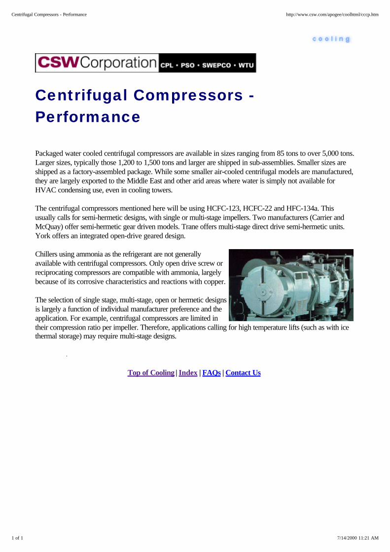
Centrifugal Compressors -Performance
Packaged water cooled centrifugal compressors are available in sizes ranging from 85 tons to over 5,000 tons.Larger sizes, typically those 1,200 to 1,500 tons and larger are shipped in sub-assemblies. Smaller sizes areshipped as a factory-assembled package. While some smaller air-cooled centrifugal models are manufactured,they are largely exported to the Middle East and other arid areas where water is simply not available forHVAC condensing use, even in cooling towers.
The centrifugal compressors mentioned here will be using HCFC-123, HCFC-22 and HFC-134a. Thisusually calls for semi-hermetic designs, with single or multi-stage impellers. Two manufacturers (Carrier andMcQuay) offer semi-hermetic gear driven models. Trane offers multi-stage direct drive semi-hermetic units.York offers an integrated open-drive geared design.
Chillers using ammonia as the refrigerant are not generallyavailable with centrifugal compressors. Only open drive screw orreciprocating compressors are compatible with ammonia, largelybecause of its corrosive characteristics and reactions with copper.
The selection of single stage, multi-stage, open or hermetic designsis largely a function of individual manufacturer preference and theapplication. For example, centrifugal compressors are limited intheir compression ratio per impeller. Therefore, applications calling for high temperature lifts (such as with icethermal storage) may require multi-stage designs.
Top of Cooling | Index | FAQs | Contact Us
1 of 1 7/14/2000 11:21 AM
Centrifugal Compressors - Performance http://www.csw.com/apogee/coolhtml/cccp.htm

Centrifugal Compressors - PowerRequirements
Power requirements for centrifugal chillers are the lowest of all chiller types currently available, and efficiencieshave been improving even further over the years as a result of improved impeller designs, better unitconfigurations, enhanced heat transfer surfaces, and the increased utility emphasis on reducing energyrequirements.
At ARI standard rating conditions centrifugal chiller's performance at full design capacity ranges from 0.53 kWper ton or lower to 0.68 kW per ton. This performance includes the semi-hermetic refrigerant cooled or opentype compressor motors.
Open drive chiller power requirements are sometimes rated in shaft brake horsepower (bhp). To convert frombhp to electric input in kW, the efficiency of the motor must be considered (which is usually between 90 and95 percent for centrifugal machines). For example, a rating of 1,000 bhp at 93 % motor efficiency wouldtranslate to 802 kilowatt input.
(1,000bhp x 0.746 kW/bhp) = 80.2 kW input 93% Motor efficiency
Top of Cooling | Index | FAQs | Contact Us
1 of 1 7/14/2000 11:21 AM
Centrifugal Compressors - Power Requirements http://www.csw.com/apogee/coolhtml/cccr.htm

Centrifugal Compressors - First Cost
Centrifugals chillers 200 tons and larger cost less to install than reciprocating chillers (available up to the 175 to200 ton range) and the same or slightly less than screw chillers in most all sizes. Centrifugals offer theadvantages of high efficiency, infinitely variable capacity control (down to about 10 percent of full load), they'relighter (which reduces floor loadings) and they take up much less space for a given tonnage.
First cost of centrifugal chiller packages generally start higher than recips under 200 tons, and then cost less inthe larger sizes. More definitive costs are shown in the Compare segment.
And Furthermore . . .
Compare - Installed Costs - Chillers
Top of Cooling | Index | FAQs | Contact Us
1 of 1 7/14/2000 11:20 AM
Centrifugal Compressors - First Cost http://www.csw.com/apogee/coolhtml/cccc.htm

Scroll Compressors
The scroll compressor uses one stationary and one orbiting scroll tocompress refrigerant gas vapors from the evaporator to thecondenser of the refrigerant path. The upper scroll is stationary andcontains the refrigerant gas discharge port. The lower scroll is drivenby an electric motor shaft assembly imparting an eccentric or orbitingmotion to the driven scroll. That is, the rotation of the motor shaftcauses the scroll to orbit - not rotate - about the shaft center.
This orbiting motion gathers refrigerant vapors at the perimeter,pockets the refrigerant gas, and compresses it as the orbitingproceeds. The trapped pocket works progressively toward the centerof the stationary scroll and leaves through the discharge port. Studythis time lapse series carefully to see how the trapped gases areprogressively compressed as they proceed toward the discharge port.
Scroll compressors are a relatively recent compressor developmentand will eventually replace reciprocating compressors in many coolingsystem applications, where they often achieve higher efficiency andbetter part-load performance and operating characteristics.
1 of 2 7/14/2000 11:25 AM
Scroll http://www.csw.com/apogee/coolhtml/ccl.htm

Top of Cooling | Index | FAQs | Contact Us
2 of 2 7/14/2000 11:25 AM
Scroll http://www.csw.com/apogee/coolhtml/ccl.htm

Mechanical Drives
Mechanical Drives - General Design Attributes
Mechanical Drives - Electric Motors
Mechanical Drives - Steam Turbines (Back Pressure & Condensing)
Mechanical Drives - Reciprocating Engines
Mechanical Drives - Gas Turbine Designs
Top of Cooling | Index | FAQs | Contact Us
1 of 1 7/14/2000 11:26 AM
Mechanical Drives http://www.csw.com/apogee/coolhtml/cxcm.htm

Mechanical Drives - General DesignAttributes
Chiller compressors can be driven by electric motors, reciprocating engines, gas turbines, or steam turbines.The selection of alternative drive technologies rests primarily on the issues of first cost and operating cost, aswell as any fuel diversity and power reliability criteria. While there are other issues involved in the selectionprocess, including CFC phaseout and other refrigerant-related issues, the selection between the alternativesjust mentioned will probably not be driven by CFCs. In other words, a refrigerant that might be applicable fora chiller driven by a reciprocating engine would also work for an electric motor drive. A discussion of thesecriteria can be found elsewhere in this digital reference library.
While mechanical drives other than electric motors are also discussed, the primary alternatives presented willbe reciprocating engines in the 100-500 ton range and steam turbines which are typically much larger. Gasturbine-driven chillers are seldom seriously considered for three reasons:
The limited number of gas turbine sizes available
Their economic reliance on heat recovery and
Their relatively poor on-peak performance during hot weather.
Top of Cooling | Index | FAQs | Contact Us
1 of 1 7/14/2000 11:26 AM
Mechanical Drives - General Design Attributes http://www.csw.com/apogee/coolhtml/ccmd.htm
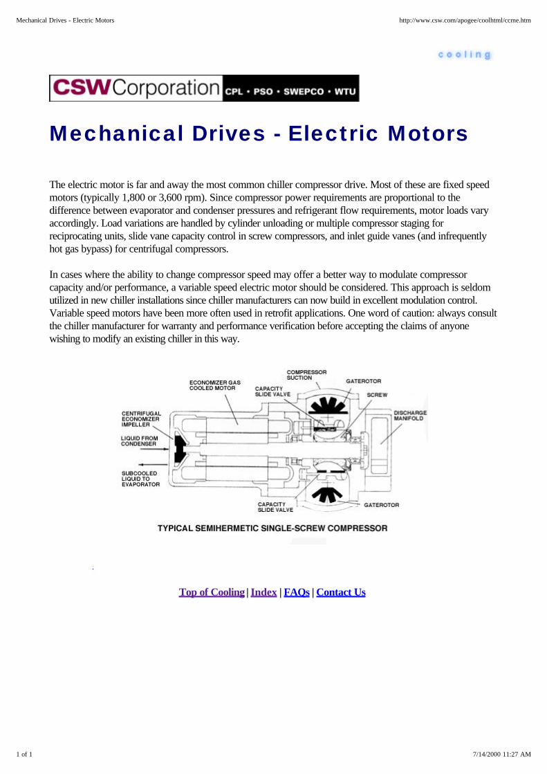
Mechanical Drives - Electric Motors
The electric motor is far and away the most common chiller compressor drive. Most of these are fixed speedmotors (typically 1,800 or 3,600 rpm). Since compressor power requirements are proportional to thedifference between evaporator and condenser pressures and refrigerant flow requirements, motor loads varyaccordingly. Load variations are handled by cylinder unloading or multiple compressor staging forreciprocating units, slide vane capacity control in screw compressors, and inlet guide vanes (and infrequentlyhot gas bypass) for centrifugal compressors.
In cases where the ability to change compressor speed may offer a better way to modulate compressorcapacity and/or performance, a variable speed electric motor should be considered. This approach is seldomutilized in new chiller installations since chiller manufacturers can now build in excellent modulation control.Variable speed motors have been more often used in retrofit applications. One word of caution: always consultthe chiller manufacturer for warranty and performance verification before accepting the claims of anyonewishing to modify an existing chiller in this way.
Top of Cooling | Index | FAQs | Contact Us
1 of 1 7/14/2000 11:27 AM
Mechanical Drives - Electric Motors http://www.csw.com/apogee/coolhtml/ccme.htm

Mechanical Drives - Steam Turbines(Back Pressure & Condensing)
Steam turbines, reciprocating engines, and sometimes gas turbines are used to drive chiller compressors. Themost common applications are very large (over 1500 tons) steam turbine-driven centrifugal chillers used incogeneration applications for large hospitals or industrial cooling. In situations where electrical demand chargesare high (say over $25 per kW per month) or where a demand ratchet could make an electric-driven chillertoo expensive to operate for a few months a year, steam turbine-driven chillers are often specified.
Why not reciprocating engines or gas turbines? Steam turbines use the existing boiler system so they don't haveto worry about fuel supply or air emissions. Since the steam needs of the site are usually dictated by the coldermonths, the existing steam generating capacity is often more than adequate to support cooling. Plus, theoperating and maintenance characteristics of steam turbine-driven chillers are much better than reciprocatingengines or gas turbine-driven equipment. Finally, where existing boiler capacity is adequate, steamturbine-driven chillers cost less than reciprocating engines or gas turbines.
There are two basic steam turbine designs: back pressure and condensing. These indicate whether steamleaving the turbine goes on into the steam distribution system to satisfy process or heating requirements (this is"back pressure"), or whether the steam leaving the turbine goes straight to a dedicated steam condenser whereit is rejected via a cooling tower or river water. Logically, condensing steam turbines are more expensive andless efficient than the back pressure designs.
When site steam requirements are reasonably steady and in excess of the steam flows necessary to drive thechiller, the back pressure design makes the most sense. Where this is not true, and power costs would be high
1 of 2 7/14/2000 11:27 AM
Mechanical Drives - Steam Turbines (Back Pressure & Condensing) http://www.csw.com/apogee/coolhtml/ccms.htm

for an electric-driven machine, a condensing steam turbine may be the most cost effective alternative.
In many cases where steam turbines are considered, rather than apply them to a chiller operating relativelylower hours a year, the turbine is typically used to drive a generator to take maximum advantage of its powergenerating capabilities.
Selecting a chiller design like this requires careful consideration of site-specific conditions. Steam turbine drivenchillers represent a complex design in any situation. It is wise to consult with qualified design professionals andreputable equipment manufacturers before making a final decision.
Top of Cooling | Index | FAQs | Contact Us
2 of 2 7/14/2000 11:27 AM
Mechanical Drives - Steam Turbines (Back Pressure & Condensing) http://www.csw.com/apogee/coolhtml/ccms.htm
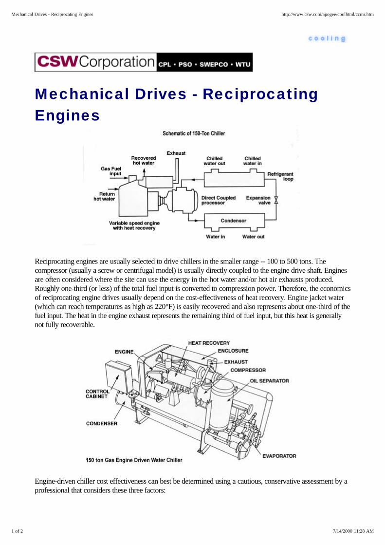
Mechanical Drives - ReciprocatingEngines
Reciprocating engines are usually selected to drive chillers in the smaller range -- 100 to 500 tons. Thecompressor (usually a screw or centrifugal model) is usually directly coupled to the engine drive shaft. Enginesare often considered where the site can use the energy in the hot water and/or hot air exhausts produced.Roughly one-third (or less) of the total fuel input is converted to compression power. Therefore, the economicsof reciprocating engine drives usually depend on the cost-effectiveness of heat recovery. Engine jacket water(which can reach temperatures as high as 220°F) is easily recovered and also represents about one-third of thefuel input. The heat in the engine exhaust represents the remaining third of fuel input, but this heat is generallynot fully recoverable.
Engine-driven chiller cost effectiveness can best be determined using a cautious, conservative assessment by aprofessional that considers these three factors:
1 of 2 7/14/2000 11:28 AM
Mechanical Drives - Reciprocating Engines http://www.csw.com/apogee/coolhtml/ccmr.htm
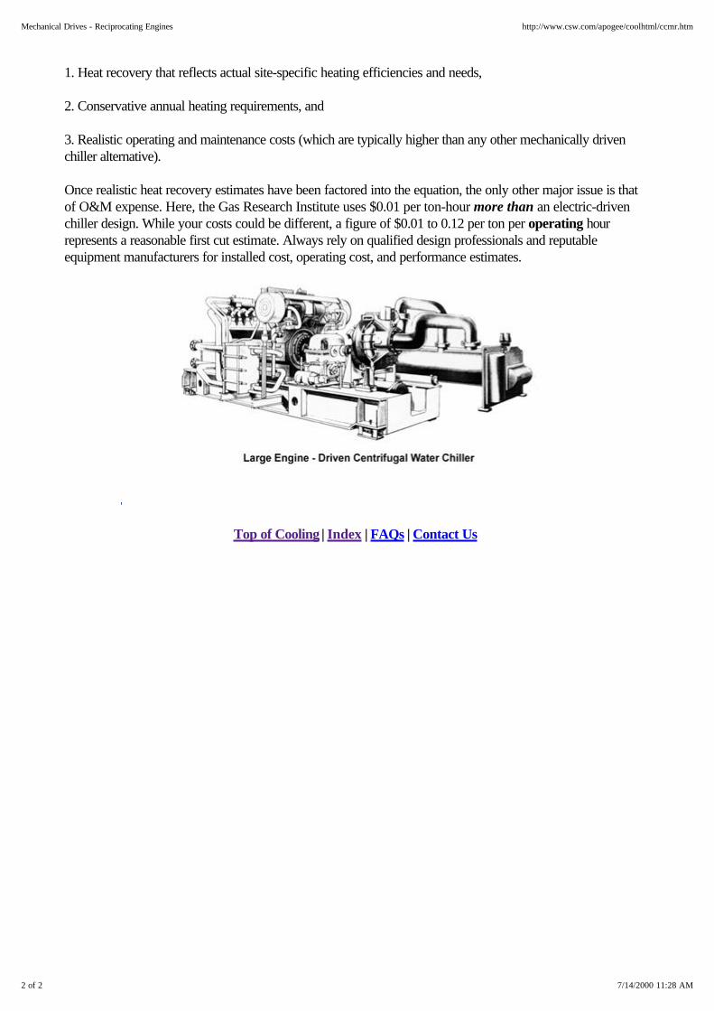
1. Heat recovery that reflects actual site-specific heating efficiencies and needs,
2. Conservative annual heating requirements, and
3. Realistic operating and maintenance costs (which are typically higher than any other mechanically drivenchiller alternative).
Once realistic heat recovery estimates have been factored into the equation, the only other major issue is thatof O&M expense. Here, the Gas Research Institute uses $0.01 per ton-hour more than an electric-drivenchiller design. While your costs could be different, a figure of $0.01 to 0.12 per ton per operating hourrepresents a reasonable first cut estimate. Always rely on qualified design professionals and reputableequipment manufacturers for installed cost, operating cost, and performance estimates.
Top of Cooling | Index | FAQs | Contact Us
2 of 2 7/14/2000 11:28 AM
Mechanical Drives - Reciprocating Engines http://www.csw.com/apogee/coolhtml/ccmr.htm

Mechanical Drives - Gas TurbineDesigns Gas turbines are seldom selected to drivechiller compressors because theefficiency of the cogeneration systemusing a gas turbine relies heavily onrecovering the engine's waste heat. Mostsites simply don't have a use for all thewaste heat. In cases where the heat canbe used, the gas turbine is typically usedto drive a generator to take maximumadvantage of its power generatingcapabilities. The main problemsassociated with using gas turbines aschiller drives include:
1. Gas turbine power levels (and theresulting chilled water production) are significantly reduced (~ 25-35%) at high ambient temperaturelevels. This means that at the very time the site needs maximum power to drive a chiller compressor, thegas turbine is least capable of delivering it. One solution might be to use some of the chilled waterproduction to cool gas turbine inlet air, but this also reduces net chilled water production.
2. Operating and maintenance procedures are relatively sophisticated. The engines must be protectedagainst inlet dust, contaminants, frosting, or damage from foreign objects. When placed in the hands ofqualified, experienced personnel, and run continuously, gas turbines have recorded extremely high
1 of 2 7/14/2000 11:30 AM
Mechanical Drives - Gas Turbine Designs http://www.csw.com/apogee/coolhtml/ccmg.htm

annual availability and low maintenance costs. Unfortunately, chillers seldom run continuously.
3. If the gas turbine is fueled with natural gas, gas pressures have to be higher than with any othermechanical driver -- typically 300 - 400 psig for the gas turbine. These pressures aren't always availablefrom suppliers, and therefore require a supplemental gas compressor. Since this gas compressor isrelatively unreliable, a "spare" is usually added in the system design, making it an expensive designattribute. Coupled with the power used to compress the natural gas fuel input, this compressor becomesa significant element in the cost-effectiveness equation.
4. Careful matching of the turbine and compressor, both available in limited size increments is essential.Starting and stopping torques are specially important. These requirements typically increase the chillercost not economically supportable.
This doesn't mean that the gas turbine is a necessarily bad choice for a mechanical drive application, it justhighlights the primary concerns the designer and owner should consider in evaluating the alternatives.Therefore, it would be prudent to rely on qualified design professionals and reputable equipment manufacturersfor gas turbine installed cost, operating characteristics, and site-specific performance estimates.
Top of Cooling | Index | FAQs | Contact Us
2 of 2 7/14/2000 11:30 AM
Mechanical Drives - Gas Turbine Designs http://www.csw.com/apogee/coolhtml/ccmg.htm
CFCs
Top of Cooling | Index | FAQs | Contact Us
1 of 1 7/14/2000 11:31 AM
CFCs http://www.csw.com/apogee/coolhtml/cxo.htm
Major Equipment Retrofit Concepts
Owners and operators must first determine whether a retrofit makes more sense than replacement. Thisinvolves an evaluation of the facility plans, and the age, efficiency, and general condition of the chiller.Reviewing service, efficiency, and refrigerant-use records will also help. "Stopgap" conversions typically usethe existing compressor, cooler and condenser. A typical stopgap conversion might include the following steps:
1. An evaluation of the system's performance and condition, along with a projection of the likelyperformance after conversion
2. Changing the CFC refrigerant in the system to an acceptable HCFC or HFC alternative
3. Converting the hardware and other components including controls, refrigerant flow devices, and reliefvalves
4. Recharging, with new refrigerant
5. Recycling, reclaiming or disposing of the old CFC refrigerant
6. Start-up services including operator training.
Converting low-pressure chiller CFC-11 to HCFC-123 requires new seals, O-rings, gaskets, and elastomers.Hermetic motors exposed to the refrigerant may have to be rewound or replaced because HCFC-123 is notcompatible with some motor winding insulation. Open-driven chiller motors are not affected because they arenot exposed to the refrigerant.
Medium-pressure chiller CFC-12 and R-500 conversions to HFC-134a require a new lubricant because theconventional mineral oils are not compatible with HFC-134a. The system is typically flushed several times toremove all traces of mineral oil and then replaced with the new ester-based oils.
This work should be done by certified technicians only. None of these conversions are "Drop In". They allrequire significant equipment modifications. Some loss of capacity and efficiency may occur in someconversions. Conversion should be performed by the original equipment supplier if possible, or an experiencedservice agency following the original manufacturer's explicit recommendations. Realize that some chillers willsimply not accommodate conversion. Carefully investigate each situation and make decisions accordingly.
Optimized conversions go one or more steps beyond the stopgap conversion to compensate for anyanticipated efficiency and capacity losses. These conversions may include changes to the compressor impeller,gear-set, operating speed, and drive.
Low-pressure refrigerant conversions may involve an impeller change or modifications. Gear set replacement isnot uncommon in medium-pressure refrigerant conversion. Conversion results can range anywhere from amoderate loss to a moderate gain in performance capacity and efficiency.
1 of 2 7/14/2000 11:32 AM
Major Equipment Retrofit Concepts http://www.csw.com/apogee/coolhtml/com.htm

Other conversion issues include upgrading the chiller machinery room to comply with the forced ventilationrequirements of ASHRAE Standard 15-94. Mechanical rooms which contain refrigerants such as HCFC-123require refrigerant monitors. Refrigerants such as HFC-134a require oxygen sensors.
Retrofit costs will vary widely. A rule of thumb is that they will run from 20 to 60 percent of the installed costof a new chiller.
Top of Cooling | Index | FAQs | Contact Us
2 of 2 7/14/2000 11:32 AM
Major Equipment Retrofit Concepts http://www.csw.com/apogee/coolhtml/com.htm
Chiller Retrofit and ReplacementIssues
The phaseout of CFCs presents an excellent excuse to replace many inefficient and unreliable cooling systems.Retrofits or conversions offer an opportunity to decrease operating and maintenance costs while improving thechiller plant's performance.
Regardless of all other considerations, users are strongly advised to practice improved preventive maintenance,leak detection and containment. CFCs are not harmful until they're released - so keep containment firmly infocus.
In general, a newer chiller (one that's less than 10 years old) should be considered for retrofit. Alternatively, it'soften more cost effective to replace chillers over 20-years old. Chillers between 10 and 20 years old must beevaluated on a case-by-case basis.
Top of Cooling | Index | FAQs | Contact Us
1 of 1 7/14/2000 11:32 AM
Chiller Retrofit and Replacement Issues http://www.csw.com/apogee/coolhtml/coi.htm

CFC Alternatives
Users have three viable options for CFC replacement in vapor compression systems. They are, HCFC 123for low pressure systems, HFC-134a for medium pressure systems and HCFC 22 for high pressure systems.All can be safely and effectively applied, especially when installed in accordance with the ASHRAE standard15 and operated under the EPA service guideline. Du Pont has stated they believe the industry norm is likely tobe somewhere in the range of 30 percent of the systems out there will be excellent candidates for retrofit.
At the end of 1995, the CFC manufacturing ceased and some supply disruptions have occurred. Refrigerant123 is manufactured by several manufacturers with plants either operating or under construction. Refrigerant123 now costs much less than R-11. Thousands of new or retrofitted units are now in operation around theworld, some for as long as 8 years. R-134a is being produced in plants around the world. Its cost is nowbelow CFC-12 . Over 1,000 systems are in operation globally. Finally, R-22 remains the lowest cost andmost widely used refrigerant in the world and a lot of systems are designed to be operated on it and a lot ofnew technology has been developed around it. The time to plan is now. The clock is running and we are in theeleventh hour. There are choices available to you for the elimination of CFCs.
Environmentally Acceptable Refrigerants Are Now Available
Alternative refrigerants have been developed that can replace CFC refrigerants with only slight changes inequipment design and minimal effects on efficiency. The current principle refrigerant substitutes are shown inthe following table. Several types of blends are being investigated in order to optimize performance whileproviding zero ozone depletion potential.
Top of Cooling | Index | FAQs | Contact Us
1 of 1 7/14/2000 11:34 AM
CFC Alternatives http://www.csw.com/apogee/coolhtml/coa.htm
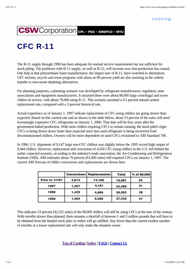
CFC R-11
The R-11 supply through 1996 has been adequate for normal service requirements but not sufficient forstock-piling. The problems with R-11 supply, as well as R-12, will increase now that production has ceased.One help is that polyurethane foam manufacturers, the largest user of R-11, have switched to alternatives.CFC reclaim, recycle and reuse programs with about an 80 percent yield are also assisting in the orderlytransfer to non-ozone depleting alternatives.
For planning purposes, a planning scenario was developed by refrigerant manufacturers, regulators, stateassociations and equipment manufacturers. It assumed there were about 80,000 large centrifugal and screwchillers in service, with about 70,000 using R-11. This scenario assumed a 4.5 percent annual systemreplacement rate, compared with a 3 percent historical rate.
Actual experience as of January 1, 1997 indicate replacement of CFC-using chillers are going slower thanexpected. Based on this current rate and as shown in the table below, about 53 percent of the units will needincreasingly expensive CFC refrigerants on January 1, 2000. That date will be four years after thegovernment-halted production. With more chillers requiring CFCs to remain running, the stock-piled virginCFCs is being drawn down faster than expected since less used refrigerant is being recovered fromdecommissioned chillers. Owners will be more dependent on used CFCs reclaimed to ARI Standard 700.
In 1996, U.S. shipments of 9,147 large non-CFC chillers was slightly below the 1995 record high output of9,444 chillers. However, replacement and conversion of 4,356 CFC-using chillers in the U.S. fell behind theearlier expected scenario, according to the industry's trade association, the Air-Conditioning and RefrigerationInstitute (ARI). ARI estimates about 76 percent (61,000 units) still required CFCs on January 1, 1997. Thecurrent ARI forecast of chiller conversions and replacements are shown here.
This indicates 53 percent (42,555 units) of the 80,000 chillers will still be using CFCs at the turn of the century.With retrofits slower than planned, there remains a shortfall of between 1 and 3 million pounds that will have tobe obtained from the limited stock piles or orders will go unfilled. Any fewer than the current modest numberof retrofits or a lower replacement rate will only make the situation worse.
Top of Cooling | Index | FAQs | Contact Us
1 of 1 7/14/2000 11:34 AM
CFC R-11 http://www.csw.com/apogee/coolhtml/coo.htm
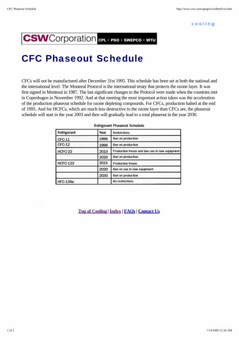
CFC Phaseout Schedule
CFCs will not be manufactured after December 31st 1995. This schedule has been set at both the national andthe international level. The Montreal Protocol is the international treaty that protects the ozone layer. It wasfirst signed in Montreal in 1987. The last significant changes to the Protocol were made when the countries metin Copenhagen in November 1992. And at that meeting the most important action taken was the accelerationof the production phaseout schedule for ozone depleting compounds. For CFCs, production halted at the endof 1995. And for HCFCs, which are much less destructive to the ozone layer than CFCs are, the phaseoutschedule will start in the year 2003 and then will gradually lead to a total phaseout in the year 2030.
Top of Cooling | Index | FAQs | Contact Us
1 of 1 7/14/2000 11:34 AM
CFC Phaseout Schedule http://www.csw.com/apogee/coolhtml/cos.htm

Refrigerant Pricing
It should come as no surprise that alternative refrigerants may tend to cost more than the refrigerants theyreplace. However, as the supplies of the alternatives increase and the taxes on CFCs increase, the alternativeswill be more and more economic for many cooling systems.
In 1989, the federal government imposed an excise tax on certain ozone-depleting chemicals. This tax hasbeen increasing late 1992. The tax was designed to penalize consumers of refrigerants with a high OzoneDepletion Potential (ODP) and bring prices closer to the then more expensive alternatives. The tax wasapplied only to new refrigerant, not recycled or reclaimed refrigerant, and was determined by multiplying thechemical's ODP by the base tax rate.
HCFC-123 costs less than CFC-11. HFC-134a is increasingly competitive with CFC-12. However, becauseof its more complex manufacturing process HFC-134a is expected to continue to cost more than HCFC-123.
Top of Cooling | Index | FAQs | Contact Us
1 of 1 7/14/2000 11:34 AM
Refrigerant Pricing http://www.csw.com/apogee/coolhtml/cop.htm

CFC Alternative Recommendations
The CFC phaseout should be viewed as an opportunity to make profitable energy efficiency upgrades inbuildings. These upgrades will help offset the overall cost of the chiller replacement or conversion. Toconclude, remember these three main points: The alternatives to CFC refrigerants are currently available. Theyeffectively address the environmental, regulatory and concerns. Second, the risks of not acting now are great.You need to consider the phaseout with sound plans and actions. And third, now is the best time to reviewopportunities for energy efficiency in buildings. That includes retrofitting building lighting systems and otherenergy-using equipment. The alternatives are ready. You need to be ready. Observe these three points andboth you and the environment will benefit.
Top of Cooling | Index | FAQs | Contact Us
1 of 1 7/14/2000 11:36 AM
CFC Alternative Recommendations http://www.csw.com/apogee/coolhtml/cod.htm

Equipment Retrofit Procedures
Most retrofits are NOT DROP-IN procedures; there are important issues to consider. When considering aretrofit to a non-CFC refrigerant, it is suggested that contact be made with the chiller manufacturer forrecommendations on the conversion and expected changes in performance. The manufacturer may offer toquote a price for performing the conversion, which can be compared to other options for performing theretrofit.
In some cases, when changing from a CFC to an alternative refrigerant, the lubricant must be changed to avoidoperational problems. Typical applications are shown here.
CFC-11 to HCFC-123
Due to compatibility issues associated with the use of R-123 in centrifugal chillers it is recommended theretrofit be evaluated on an individual basis by a qualified representative of the chiller manufacturer or certifiedservice personnel. Modifications required may include impeller and/or gear changes, seal and gasketreplacement, and possibly motor modifications on semi-hermetic units. All manufacturer's guidelines andprocedures should be followed carefully in order to achieve optimal results.
CFC-12 to HFC-134a
These are typical steps taken in retrofitting a chiller from an existing CFC refrigerant to this environmentallyacceptable alternative refrigerant.
1. Gather baseline data from the present system to be used to optimize the system when using thealternative refrigerant. Note the current CFC charge in pounds, lubricant type and charge (in pints,quarts, gallons, etc.), existing operating temperatures and pressures, and overall system performance.Leak test the system and repair is needed.
2. Removal of existing mineral oil from the system, with residual content reduced to less than 5%. This istypically done by draining the mineral oil from all accessible points in the system and replacing with anequivalent charge of polyester lubricant. The system is then operated with the R-12 sufficiently to insuremiscibility of the two lubricants. Test for residual mineral oil content and repeat procedure until theresidual content is reduced to less than 5%. Typically this takes three cycles operating at 24 hour
1 of 2 7/14/2000 11:35 AM
Equipment Retrofit Procedures http://www.csw.com/apogee/coolhtml/coq.htm

intervals.
3. Recover the existing R-12 charge and lubricant charge using standard industry recovery equipment andguidelines. A number of refrigerant recovery services are available commercially.
4. Replace filter driers with new cores. Examine sight glass for compatibility to necessary new (150 ppm)moisture-level indication levels. As new refrigerants can retain more moisture, do not omit this step.
5. Evacuate the system using a deep vacuum (at least 500 microns) to insure all remaining moisture hasbeen removed.
6. Charge system with the proper polyester lubricant and HFC-134a refrigerant. Typically the R-134acharge will be about 90% of the original charge. Refer to pressure-temperature charts for finaladjustment. Visual indication through the sight glass is not recommended as the nature of the refrigerantand lubricant is to appear cloudy in the liquid portion of the system.
7. Place proper markings and identification on the system to indicate the retrofit to R-134a and polyesterlubricant. Indicate the pounds of the new R-134a charge in a visible location.
8. Start the system and make final expansion valve adjustments to achieve the proper superheat settings.Typical normal R-134a operating pressures are 2-5% lower on the evaporator side and 2-5% higheron the condenser side.
Top of Cooling | Index | FAQs | Contact Us
2 of 2 7/14/2000 11:35 AM
Equipment Retrofit Procedures http://www.csw.com/apogee/coolhtml/coq.htm
Low-Cost Retrofit Concepts
Refrigerant strategy options are largely based on containment plus the Three R's - Recover, Recycle, Reuse.There are many ways to mitigate refrigerant loss. First, users should develop maintenance and refrigerant-uselogs to track these costs. The following low cost steps may be appropriate depending on the age, type, andsize of the cooling equipment:
Check for refrigerant leaks frequently Replace or repair all leaky fittings and valves Add isolation valves to allow safe refrigerant evacuation before repair Install refrigerant valves with cap, and really use them. Make sure valve packings and seals are rated for the refrigerant used. Use back-seating valves to minimize valve-stem leakage Use dual-relief valves (in addition to rupture discs) to allow valve repairs during system operation.
After implementing these low-cost options, carefully consider the next step involving additional investments inthe existing equipment. These concepts include:
With CFC-11 chillers, make sure the chiller has the improved, high efficiency purge unit. If it doesn't,consider having one installed. Purge units are the largest source of CFC-11 release; some of the oldones release from 4 to 10 pounds of CFC-11 per pound of air. The new units reduce this loss to aminimum -- some as low as 0.005 pounds CFC-11 per pound of air. This is less than 1% per year ofthe refrigerant charge.
With CFC-11 and HCFC-123 chillers, make sure the chiller is equipped with a repressuring system tofacilitate leak detection. Again, if it's not, consider installing one. A vessel repressuring system is usedwith low-pressure refrigerant systems that operate at a vacuum. This system prevents a vacuumcondition during shutdown periods and thereby reducing air infiltration by heating the refrigerant and thuspressurizing the system. This cuts the time and expense of leak-testing by eliminating the pressurizationwith an inert gas (e.g., nitrogen) and limiting refrigerant losses during purging procedures. It can alsohelp stop leaks until they can be located and corrected.
Use a refrigerant recovery device to drain refrigerant during maintenance and non-cooling seasons.
Use a refrigerant transfer-and-storage receiver system.
Install and use an oxygen sensor or vapor detector that will provide a warning when refrigerant isleaking, and comply with the new safety codes.
Top of Cooling | Index | FAQs | Contact Us
1 of 1 7/14/2000 11:35 AM
Low-Cost Retrofit Concepts http://www.csw.com/apogee/coolhtml/col.htm

CFC Action Steps
Building owners must get passionate about refrigerant containment and emission reduction. We need to getbelow 10 percent. Preferably to 5 percent of a system's charge on an annual basis, from our historic rate of20-25 percent. The ability to do this is available now from equipment manufacturers and also under the newEPA service guidelines. The options available today at modest cost are recovery devices, high efficiencypurges that reduce purge losses up to ten-fold, downtime vacuum preventers that minimize the need to evenoperate the purges, and pressure relief attachments. And finally, fix leaks rather than just top off. Once we getemissions under control, owners should next evaluate the retrofit of their existing equipment versusreplacement. Each chiller is different. Owners need to contact their equipment manufacturers for compressorperformance and alternative refrigerants.
This will provide you with the estimated cost to convert your system and give you the basis to develop aneconomic comparison of retrofit versus replacement. Then you need to evaluate your options on a lifetimeoperation cost basis and develop a plan for an orderly withdrawal from CFCs.
Top of Cooling | Index | FAQs | Contact Us
1 of 1 7/14/2000 11:37 AM
CFC Action Steps http://www.csw.com/apogee/coolhtml/coc.htm

CFC R-12
R-12 users have been more affected by the 1996 phaseout than others due to its wide spread use and thehighly emittive nature of many key R-12 applications, such as automotive air conditioners, single dosemedication inhalers, and ethylene-oxide sterilizers. The real problem has been increasing since productionhalted at the end of 1995. There are about 142 million vehicles with air conditioning systems driven by R-12.There are tens of thousands of additional small systems at the secondary retail level. Most large chain storesare well into, or have completed, their transition.
Users have been responding to choices they have regarding retrofit, replacement, or recharge when theirsystems go down. Currently they seem willing to pay a high price for R-12; in 1996, reports indicated virginR-12 sold at wholesale for $285 ($9.50 per pound) in 30lb cylinders. At the height of the 1996 coolingseason prices rose to over $600 per cylinder ($20 per pound). Owners of large systems like chillers who needfairly large quantities of refrigerant to keep their systems running will be at a distinct disadvantage versus thesefolks. At some future point the replacement of a lost charge on a chiller exceed the cost of either retrofitting itor even buying a new unit if the cost of R-12 is at or near $100 per pound. And again, $100 per pound couldoccur - but not yet - as the shortfall of demand versus supply following the phaseout could reach at 20-50million pounds.
Top of Cooling | Index | FAQs | Contact Us
1 of 1 7/14/2000 11:37 AM
CFC R-12 http://www.csw.com/apogee/coolhtml/cot.htm

EPA Regulations
EPA's authority is to regulate protection of the earth's air is the Clean Air Act. Here we will look at just threeof the major regulations of the Clean Air Act that most directly affect building owners and managers. TheAccelerated Production Phaseout, the Mandatory Refrigerant Recycling Regulation, and the Significant NewAlternatives Policy or SNAP. CFC production ceased at the end of 1995. HCFCs under the Clean Air Actwill be treated differently but will be treated consistent with the Montreal Protocol. One proposal distinguishesamong chemicals based on their ozone depleting potential and takes into account whether a chemical has ashort versus a long atmospheric lifetime as well as the chemical's application.
The two major HCFCs used by the air conditioning industry are R-22 and R-123. EPA has proposed differentphaseout dates. HCFC 141b, which is not used by the building air conditioning industry, but is mainly used asa foam blowing agent, has a high ozone depletion potential, and as a result, the proposed phaseout date for thischemical is 2003. The phaseout schedule for 22 is two-tiered. It will start in 2010 for new equipment and willbe phased out completely in 2020, at which point it will be available for servicing existing equipment.HCFC-123, which has a low ozone depletion potential, is not being phased out in new equipment until 2020,and for existing equipment, in 2030. Remember, that 22 and 123 play a valuable role as replacements forCFCs and are expected to be available over the useful lifetime of existing equipment.
The Clean Air Act also significantly affects the way air conditioning systems will be serviced. The main goal isreducing the emissions to the lowest achievable level. An effective recycling program is important to conservingthe existing supply of CFC refrigerant and preventing the release to the atmosphere. The law prohibitsintentional venting of refrigerants during the service, maintenance, repair and the disposal of air conditioning orrefrigerant equipment. In May 1993, EPA released the rule implementing the Clean Air Act on the properhandling of refrigerants. These regulations established the required service practices technicians must followwhen working on these systems. The equipment technicians use to recover and recycle refrigerants must meetcertain standards. And the technicians themselves must pass an exam demonstrating their knowledge. Theregulations also require large systems be repaired and refrigerant recovered upon disposal.
Owners of chillers and other refrigeration and air conditioning systems having a charge greater than 50 poundsthat leaks over 15 percent per year, have 30 days to repair the leak. If the leak is not repaired, a plan must bedeveloped to retire or retrofit the system and it must be implemented within one year. EPA will enforce these,and the Act allows penalties up to $25,000 per violation.
Now let's look at SNAP. This section of the Clean Air Act authorizes EPA to determine the acceptability ofthe alternatives replacing CFCs and in time will cover the HCFCs. It's not enough that the substitutes justprotect the ozone layer. EPA must evaluate the alternatives based on overall risks. The criteria the alternativesare weighed against include ozone depletion, global warning potential, energy efficiency and the safety,including toxicity, flammability and other environmental and health factors.
Top of Cooling | Index | FAQs | Contact Us
1 of 1 7/14/2000 11:46 AM
EPA Regulations http://www.csw.com/apogee/coolhtml/coe.htm
CFC Regulatory History
In response to concerns about ozone depletion caused by CFCs, representatives of the world communityconvened in Montreal in 1987, London in 1990, and Copenhagen in 1992. Additionally, the United StatesGovernment passed the Clean Air Act in 1992 which accelerated the CFC phaseout.
The outcome of all these meetings was:
Production of CFCs stopped in 1996. It's interesting to note that some manufacturers phased outproduction a year earlier. HCFCs production will be cut to 65 percent of 1989 production by the year 2004.
The rest of the HCFC phaseout looks like this:
In the year 2010, production and consumption of HCFC-22 will be frozen at baseline levels and therewill be a ban on the use of HCFC-22 in new cooling equipment. In 2016, production and consumption of HCFC-123 will be frozen at baseline levels In 2020, HCFC-22 will be totally banned. HCFC-123 will not be available for use in new equipment. In 2030, HCFC-123 will be totally banned. There are no restrictions on HFC-134a and other alternative refrigerants being developed chlorine-free.
However, it is also fair to point out that many rulings change over time. One only has to remember theASHRAE changes to ventilation rates to see how things can change.
Top of Cooling | Index | FAQs | Contact Us
1 of 1 7/14/2000 12:07 PM
CFC Regulatory History http://www.csw.com/apogee/coolhtml/coh.htm

Refrigerant Properties and Safety
The properties of refrigerants and refrigerant safety can be categorized in several ways, including:
Ozone Depletion Potential (ODP). Ozone in the upper atmosphere provides protection for animals andplants from the large ultraviolet component of sunlight. ODP refers to the damage a substance can causeto ozone in the stratosphere measured relative to CFC-11 which is defined with an ODP of 1.
Global Warming Potential (GWP). GWP indicates a substance's ability to trap heat in the atmosphereover a period of time, called an integrated time horizon or ITH. The measurement is relative to CFC-11or carbon dioxide, and an ITH of 100 years is typical for CFCs, HCFCs and HFCs.
Both direct GWP and indirect GWP are considered in refrigerant environmental impact. Direct is fromthe refrigerant itself. Indirect considers the carbon dioxide and other emissions produced at the powerplant that supplies electricity to the cooling system.
Flammability considers the refrigerant/air ratio, pressure, temperature and potential sources of ignition.ASHRAE rates systems from "no flame propagation" Class 1, to the more flammable Class 2 and 3substances.
Personnel exposure limits are established using toxicology tests. The Threshold Limit Value (TLV) setsthe amount of time most workers may be exposed to a substance during an eight hour day and 40-hourweek without adverse effects. Other measures include Acceptable Exposure Limit (AEL) published byrefrigerant manufacturers, and Permissible Exposure Limit (PEL) published by the federal government.Again, ASHRAE rates systems from Class A (lower toxicity) to Class B (more toxic).
Additionally, ASHRAE Standard 15 requires that for Class A1 refrigerants (that's "A" for lower toxicity, and"1" for no flame propagation), equipment rooms must be equipped with oxygen sensors to warn of oxygenlevels below 19.5 percent. For other refrigerants, a vapor detector must be installed to warn of potentiallyharmful concentrations of refrigerant vapors.
Two other issues relate to this discussion:
1. CFCs are no longer listed by the Environmental Protection Agency as a hazardous waste. The original1990 rule has been suspended.
2. Local building codes may not yet allow the use of HCFC-123, HFC-134a, and other alternativesbecause the codes have not yet been updated. At present, the major model code groups have acceptedan interim proposal recognizing the alternative refrigerants. The needed official code changes areforthcoming. Check them in your area.
Top of Cooling | Index | FAQs | Contact Us
1 of 2 7/14/2000 12:08 PM
Refrigerant Properties and Safety http://www.csw.com/apogee/coolhtml/cor.htm

2 of 2 7/14/2000 12:08 PM
Refrigerant Properties and Safety http://www.csw.com/apogee/coolhtml/cor.htm

Compare
In the absence of current project-specific cost information, the values shown in these segments can be used tocompare chiller alternatives.
Top of Cooling | Index | FAQs | Contact Us
1 of 1 7/14/2000 12:08 PM
Compare http://www.csw.com/apogee/coolhtml/cxm.htm

Compare - Installed Costs - Centraland Unitary Systems
For comparison purposes, this table illustrates some typical relative installed costs of several popular systems.
Top of Cooling | Index | FAQs | Contact Us
1 of 1 7/14/2000 12:09 PM
Compare - Installed Costs - Central and Unitary Systems http://www.csw.com/apogee/coolhtml/cmncu.htm

Compare - Installed Costs - Chillers
Installed costs and capital offsets are important economic parameters. The installed cost of electric chillers issignificantly lower than comparable heat-driven chillers. Heat-driven Chillers require larger cooling waterpumps and towers. Engine driven chillers have a prime mover that costs much more than a comparable electricmotor (and has much higher maintenance costs as well). Absorption chillers are much more costly thancomparable sized electric chillers.
While the factory price of a chiller unit may be easy to obtain, a more meaningful economic comparison isbased on the estimated total installed cost. This figure should include the chiller plus associated cooling towerand condenser water pumps and piping or air-cooled condenser, plus delivery of the equipment to the job site,and installation with interconnecting tower/chiller/pump piping and controls, including the contractor's overheadand profit.
Where any one cost segment is constant for all alternatives (such as chilled water distribution pumps andpiping), this cost can be omitted since it will not affect the outcome comparison. In some cases, thecomparison is simplified if incremental costs are used; that is, one chiller is considered the base and the otheralternatives are assessed at how much more or less they cost. For example if one chiller requires 100 morekW service than another, than the incremental service cost is estimated at $45/kW. That chiller's incrementalcost would be $4,500 more than the base unit's cost.
In the absence of current, project specific, installed cost figures, these charts and tables can be used toestimate and compare costs.
The costs shown are typical of large water chiller installed costs including cooling tower with pump piping andinstallation or air-cooled condenser. They are at nominal tons capacity and HCFC-123 or HFC-134acompatible.
Electric Reciprocating Chillers - Air - and Water-Cooled Electric Centrifugal/Screw Chillers - Water-Cooled Absorption & Engine Drive Chillers - Water-Cooled
1 of 3 7/14/2000 10:25 AM
Compare - Installed Costs - Chillers http://www.csw.com/apogee/coolhtml/cmnch.htm

The values provided reflect new construction in a typical building in a representative U.S. city with median
2 of 3 7/14/2000 10:25 AM
Compare - Installed Costs - Chillers http://www.csw.com/apogee/coolhtml/cmnch.htm

labor rates. For units larger than 1,000 tons, the installed cost per ton declines only slightly on a dollar per tonbasis. Costs shown are mid-1995 estimates for a single package chiller. On many installations, multiple units ofequal or mixed capacities are used. Again, location, labor rates, rigging, control options, and unit efficiency cansubstantially affect the actual installed cost, which can vary as much as +25%.
Some gas suppliers will subsidize the higher installed costs of engine-driven and absorption chillers. One waythey do this is to absorb a percentage of the cost premium. Others will offer incentives, anywhere from $100to $150 or more per ton, to reduce the installed cost premium. There is no way to be certain how long theseincentives may continue.
Top of Cooling | Index | FAQs | Contact Us
3 of 3 7/14/2000 10:25 AM
Compare - Installed Costs - Chillers http://www.csw.com/apogee/coolhtml/cmnch.htm

Compare - Operating andMaintenance Costs - Chillers
Operating and maintenance (O&M) costs include the day-to-day costs keeping the equipment running. It iswise to keep these estimates on the conservative side since the economic analysis will contribute to a prudentfinancial judgment. This is not the place for optimism. Operating costs depend largely on the relative electricand gas rates. It is vital that the demand charges and energy costs of each alternative be calculated separatelyand consider any seasonal or time-of-use provisions. Never use "average rates."
Building codes or other considerations may dictate the need for operating personnel. If this is the case,personnel costs must be included. And don't forget to add the energy and water prices to the energyconsumption rate of each chiller alternative on a "level playing field" basis. Maintenance costs for screw andcentrifugal chillers are typically lower than for absorption chillers, since these chillers require more frequentreplacement of mechanical components, tube stresses are higher, and there are simply more tubes to replace.Costs for engine-driven chillers are even higher since they require engine maintenance in addition to the samemaintenance costs as an electric chiller.
In the absence of current, project-specific maintenance costs, these two charts and tables can be used toestimate annual maintenance costs of non-CFC chillers.
Electric Reciprocating Chillers - Air- and Water-Cooled Centrifugal (& Screw) and Absorption Chillers - Water-Cooled
1 of 3 7/14/2000 10:20 AM
Compare - Operating and Maintenance Costs - Chillers http://www.csw.com/apogee/coolhtml/cmomc.htm
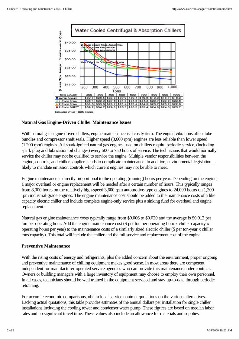
Natural Gas Engine-Driven Chiller Maintenance Issues
With natural gas engine-driven chillers, engine maintenance is a costly item. The engine vibrations affect tubebundles and compressor shaft seals. Higher speed (3,600 rpm) engines are less reliable than lower speed(1,200 rpm) engines. All spark-ignited natural gas engines used on chillers require periodic service, (includingspark plug and lubrication oil changes) every 500 to 750 hours of service. The technicians that would normallyservice the chiller may not be qualified to service the engine. Multiple vendor responsibilities between theengine, controls, and chiller suppliers tends to complicate maintenance. In addition, environmental legislation islikely to mandate emission controls which current engines may not be able to meet.
Engine maintenance is directly proportional to the operating (running) hours per year. Depending on the engine,a major overhaul or engine replacement will be needed after a certain number of hours. This typically rangesfrom 8,000 hours on the relatively high-speed 3,600 rpm automotive-type engines to 24,000 hours on 1,200rpm industrial-grade engines. The engine maintenance cost should be added to the maintenance costs of a likecapacity electric chiller and include complete engine-only service plus a sinking fund for overhaul and enginereplacement.
Natural gas engine maintenance costs typically range from $0.006 to $0.020 and the average is $0.012 perton per operating hour. Add the engine maintenance cost ($ per ton per operating hour x chiller capacity xoperating hours per year) to the maintenance costs of a similarly sized electric chiller ($ per ton-year x chillertons capacity). This total will include the chiller and the full service and replacement cost of the engine.
Preventive Maintenance
With the rising costs of energy and refrigerants, plus the added concern about the environment, proper ongoingand preventive maintenance of chilling equipment makes good sense. In most areas there are competentindependent- or manufacturer-operated service agencies who can provide this maintenance under contract.Owners or building managers with a large inventory of equipment may choose to employ their own personnel.In all cases, technicians should be well trained in the equipment serviced and stay up-to-date through periodicretraining.
For accurate economic comparisons, obtain local service contract quotations on the various alternatives.Lacking actual quotations, this table provides estimates of the annual dollars per installation for single chillerinstallations including the cooling tower and condenser water pump. These figures are based on median laborrates and no significant travel time. These values also include an allowance for materials and supplies.
2 of 3 7/14/2000 10:20 AM
Compare - Operating and Maintenance Costs - Chillers http://www.csw.com/apogee/coolhtml/cmomc.htm

Multiple Units
For multiple units at a single location, make the calculation as if the units were singly installed and multiply thetotal dollar chiller only maintenance cost of all units (not including gas engine maintenance) by a 0.80 multiplierfor two units at single location, or a 0.70 multiplier for three or more units at single location. For engine-drivenchillers, add in the engine-only maintenance costs.
Top of Cooling | Index | FAQs | Contact Us
3 of 3 7/14/2000 10:20 AM
Compare - Operating and Maintenance Costs - Chillers http://www.csw.com/apogee/coolhtml/cmomc.htm