cooling system and radiator group
TRANSCRIPT
••••••
COOLING SYSTEM & RADIATOR
L-LINE MOTOR TRUCK SERVICE MANUAL Index Page 1
COOLING SYSTEM AND RADIATOR GROUP
INDEX
Page Specifications .••...... <~ 1-3
SECTION "An
Antifreeze solutions, •..•. 1
C leaning the cooling s ys tern • 1
Coolant service •••.•.. 6• • • •• • \I •
Cooling system servicing. 3
Draining cooling system I
General information. 6
Leaks ••.•. 6
Neutralizing 4
Pressure flushing. 5
Radiator cap ..•. 2
Radiator mountings. 2 to 6
Rust prevention ••....•. I
~RIN'rEO IN UNITED ST~TES OF" AMERICA
Donated by John & Susan Hansen - For Personal Use Only

Donated by John & Susan Hansen - For Personal Use Only
----- ---
-- --
-----
---
--
--- --
--- --
---
-----------
---
-- --
--
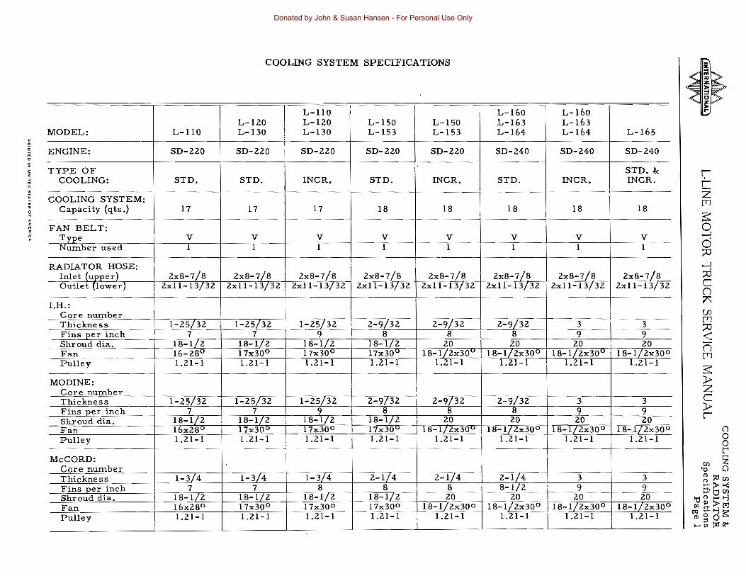
COOLING SYSTEM SPECIFICATIONS
MODEL:
ENGINE:
TYPE OF COOLING:
.COOLING SYSTEM:
Capacity (qts.)
FAN BELT: Type NUInber used
RADIATOR HOSE: Inlet (upper) Outlet (lower)
I.H.: Core nUInber Thickness Fins per inch Shroud dia. Fan __________________ Pulley
MODINE: Core nUInber Thickness Fins per inch Shroud dia. Fan Pulley
McCORD: Core number Thickness Fins per inch Shroud dia. Fan Pulley
L-IIO
SD-110
STD.
17
V 1
2xS-7/S 2xll-13/32
1-25/32 7
lS-1/2 16-2So
----1:21-1
1-25/3l 7
lS-1/2 l.l)xl8u I.l1-1
1-3/4 7
lS-1/2 16xl8° 1.l1-1
L-110 L-ll0 L-ll0 L-150 L-130 L-130 L-153
SD-l20 SD-l20 SD-2l0
STD. INCR. STD.
17 17 IS -
V __~__ V V -~-----l--- 1 1
2xS-7/S lxS-7!S 2xS-7/S 2xll-13/32 2xfl-13/32 2xll-13f32
1-25/32 -1-25/32 2-9[32 7 9 8
18-1/2 lS-I/2 18-1/2 -17x300 17x30o 17x30o
1:ll-1 --
1.21-1 1.21-1
1-25/32 l-l5/32 2-9/32 7 9 8
IS-1/2 lS-1/2 18-I/l 17x30u 17x30 o 17x30v
I.l1-1 1.21-1 1.21-1
1-3/4 1-3/4 2-1/4 7 8 8
lS-1/2 lS-1/2 IS-I/l 17x30o 17x30 o 17x30o 1.21-1 1.21-1 1.l1-1
L-150 L-153
SD-110
INCR.
IS
V 1
2xS-7/S 2xll-13j32
2-9/32 S
20 TS-f/2x30u
1.21-1
~ :-9/32 8
20 IS-Illx30 u
1.21-1
2-1/4 S 20
IS-1/lx30o 1.l1-1
L-160 L-163 L-164
SD-l40
STD.
18
V I
2x8-7/S 2.xll-13/32
.
2-9/32 S 20
IS-1/2x30 o 1.21-1
2-9/32 S lO
18-1/lx30o 1.21-1
2-1/4 S-1/2
20 18.... 1/2x30o
1.21-1
L-160 L-163 L-164
SD-240
INCR. ----~----
IS
V 1
2xS-7/S 2xll-13f32
3 <]
20 IS-1/lx30o
1.21-1
3 9 lO
IS-1/2x30 o 1.21-1
3 9
20 18-1/2x30o
I.l1-1
L-165
SD-240
STD. & INCR.
IS
V 1
lxS-7/S 2xll-13/32
3 9 20
lS-1/lx30 0
1.21-1
3 9 20
18- 1/2x3()O 1.21-1
3 9 20
lS-IZlx30o 1.21-1
~ C z [T1
o ~
-l o :;:0
-l :;:0 C (") 7:: (f) [T1 :;:0 < n [T1
~ :PZ C :Pr
(1 o a t"'
I:Il Z "0 Cl ~?:ll:ll :::;>>< .... tj I:Il
~nHI-j Pl~>M
OQ .... I-j!;;7ro§o;::" I-{Il?:l~
Donated by John & Susan Hansen - For Personal Use Only
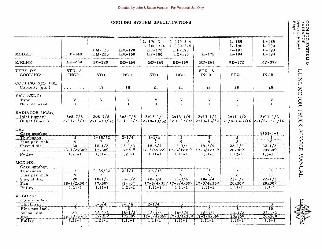
COOLING SYSTEM SPECIFICATIONS "den!Alc) 1»'l:I >0 OQ~tjO
(11 .......... r-N~> .....
_.... --.~- ..... ~- .......-.-...-. ~- .. ........ ........ °>-1Z
L-I70-3-4 L-180 ... 3-4
I L-170-3-4 L-180-3-4
L-IS5 L-190
L-lS5 L-190
!!OClo' !AI en ::l .<
MODEL: LB-I40 LM-IlO LM-l50
LM-IlO LM-I50
LF-170 LF-180
LF-170 LC-I80 L-175
L-193 L-194
L-193 L-194
II> en >-1 t'1 ~
ENGINE: SD-110 SD-ZZO BD-l69 BD-l69 BD-l69 BD-l69 RD-372 RD-372 l1:"
TYPE OF STD. &: STD. &: r;COOLING: INCR. STD. I INCR. STD. INCR. INCR. STD. INCR. C z
COOLING SYSTEM: [T1
Capacity (qts.) . . ,. "' .. . .. 17 18 II II lS l8 ~ FAN BELT:
Type Number used
V 1
V 1
V 1
V 1
V 1
V 1
V 1
V 1
o -1 o ~
RADIATOR HOSE: Inlet (upper) Outlet (lower) .
I !
lx8-7!8 lxll-13/32
lx8-7!8 lx11-13/3l
lx8-7/8 lxl1-13/3l
lx13.:.!L4 2xIO-13!3z
lx13-1!4 lxlO-13/3l
I lxI3-1!4 lxII-Ill
lxlO-13/3l. l-1/8xI3-1/16 lx11-1/l
l-I/8x13-1/16
-1 ::::0 C (J r:
I.H.: Core number SI03-1-1
{fJ [T1
Thickness Fins per inch Shroud dia,
- Fan Pulley
3 9
20 I 18-I/lx30o
I 1.l1-1
I-l5/3l 7
18-1/l 17x30o
1.21-1
'.
l-I/4 8
18-l/l 17x30o
1.21-1
l-I/4 7
18-3/4 17-3/4x350
1.11-1
3 9
18-3/4 17-3L4x35°
1.11-1
3 9
18-3/4 17-3/4x350
1.11-1
3 8
22-1/l lOx30o 1.13-1
3 10
ll-l/l lOx30o
1.3-1
~ < () [T1
~ MODINE:
Core number Thickness Fins :eer inch
.
3 9
I I
1-l5/3l 7
l-I/4 8
l-9/3l 7
3 9
3 9
3 S
3 10
:t> z c :t> r
Shroud dia. Fan Pulley
ZOI18-1/Zx300
I 1.21-1 I
lS-1/l 17x3Oo
1.l1-1
lS-1/l 17x30o 1.21-1
lS-3/4 IS-3/4 17-3j4x35° 17-3/4x35°
1.11-1 1.11-1
18-3/4 17-3/4x35°
1.11-1
ll-l/l lOx30 o
1.13-1
ll-l/l lOx3Oo
1.3-1 -
McCORD: I
Core number Thickness 3 1-3/4 l-I/4 l-l/;r 3 3 3 3 Fins per inch 9 7 S 7 9 9 S 10 Shroud dia. Fan
lO lS-1I2x30 o
lS-l/l17x.;Ou
lS-l/2 17x30o
18-3/4 17-3/4x350
18-3/4 17-3/4x350
18-3/4 17-3/4x350
22-112 20x30 o
22-1/2 20x30o
Pulley 1.21-1 I
1.21-1 j
·1.l1-1 I
1.11-1 I
1.11-1 I
1.1l-1 I
1.13-1 I -
1.3-1 - --_ ....
Donated by John & Susan Hansen - For Personal Use Only
---
----
--- --
-----
----
---- ---- ---
----
------
---
--
---
----
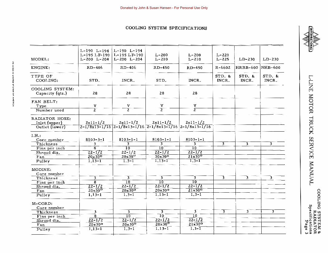
COOLING SYSTEM SPECIFICATIONS
L-190 L-194 L-190 L-194 L-195 LF-190 L-195 LF-190 L-200 L-200 L-220
MODEL: L-200 L-204 L-200 L-204 L-210 L-210 L-225 LD-230 LD-230 --- ---r------
ENGINE: RD-406 RD-406 RD-450 RD-450 R-6602 HRBB-600 NHB-600
TYPE OF STD. 8:: STD. 8:: STD. 8:: r;COOLING: STD. INCR. STD. INCR. INCR. INCR. INCR. C- z
COOLING SYSTEM: [T1 Capacity (qts.) 28 28 28 28
3;: FAN BELT:
Type V V V V o ~
Number used 2 2 2 2 ~
RADIATOR HOSE: -! Inlet (upper1 2xll-l/2 2xll-1/2 2xll-1/2 2xll-1/2 ~
COutlet (lower) 2-1/8x13-l/16 2-T/8x13-1/16 2-1/8xI3-1/l6 2-1/8xI3-1/16 --- (')
ALH.:
(J)Core number 8103-3-1 8103-1-1 8103-1-1 8103-1-1 - [T1Thickness 3 3 3 3 3 3 3 ~ Fins pe r inch 8 10 10 10 < Shroud dia. 22-1/2 22-1/2 22-1/2 22-1/2 n Fan 20x30o 20x30u 30x30o 21x30u [T1 Pulley 1.13-1 1.3-1 1.13-1 1.3-1
- --- --- 3;: MODINE; » zCore number ---- cThickness 3 3 3 3 3 3 3 »Fins per inch 8 10 10 10 -c------ r
Shroud dia. 22-1/2 22':'1/2 22-1/2 22-1/2 Fan 20x30o 2Qx30o
--20x30 o 2lx30o (j
Pulley 1.13-1 1.3-1 1.13-1 1.3-1 o o t'....McCORD: til Z
Core number 'd (}
Thickness 3 ---
3 3 3 3 3 3 ~ ~ tilFins per inch ___ 8 10 10 10 ~ >< ..... til Shroud dia. 22-1/2 22-1/2 22-1/2 22-1/2 't!0t-<J1 Fan
-~--
20x30o 20x30o 20x30u 2lx30o Pl~;J>M OQ ..... J1!:l"
Pulley -------cT3-1 1.3-1 1.13-1 1.3-1 ~goi'>l W{l)::ct~
Donated by John & Susan Hansen - For Personal Use Only

Donated by John & Susan Hansen - For Personal Use Only
COOLING SYSTEM & RADIATOR
L-UNE MOTOR TRUCK SERVICE MANUAL Section A Page I
COOLING SYSTEM AND RADIATORS
COOLING SYSTEM AND RADIATORS
Rust Prevention
(Also see "Cooling System Servicing" paragraphs.)
One of the common causes of engine overheating is a rust-clogged cooling system. Rust is the result of water action on steel and iron when air is present. Scales originate from impurities in the water used in cooling system. Rust and scales interferes with circulation and cooling, causing overheating.
Rust and corrosion formation can be prevented by maintaining full strength corrosion protection at all times.
For rust protection during the winter months, a fresh filling of an anti-freeze containing an effective corrosion preventive should be installed in the fall. In the spring, drain and discard the old anti-freeze solution because the cooling liquid may have become contaminated by corrosive impurities during use, and the rust preventives or "inhibitors" in the anti freeze solution may have become weakened and exhausted in continual driving.
During the summer, a rust preventive should be added to the cooling system to protect the systern against corrosion during warm weather operation. This inhibitor solution should be drained in the fall and a fresh filling of chemically treated anti-freeze solution again installed.
Cleaning The Cooling System
(Also see "Cooling System Servicing" paragraphs.)
Approximately twice a year, or oftener, depending upon kind of cooling water used, the cooling system should be drained and thoroughly flushed out. This is particularly important before using an anti-freeze solution.
Unless the cooling water is treated with a corrosion preventive, rust and scale will eventually clog up passages in radiator and water jackets. This condition is aggravated in some localities by the forrnation of insoluble salts from the water used.
Cleaning solutions are available which have proven very successful in removing the accumulation of rust, scale, sludge and grease. These solutions should be used according to the manufacturer1s recommendation.
Hno commercial cleaning solution is avail able, dissolve about 4 pounds of ordinary washing soda in sufficient wa te-r to fill the complete cooling system. Leave radiator filler cap off and run engine for about 1/2 hour or until engine gets hot. Then drain and flush thoroughly with clean water.
When draining the cleaning solution, dis ... connect the radiator outlet hose, as large particles of sediment will not pass through the drain cock.
If radiator is clogged with insoluble salt formations it should be taken to a reputable concern specializing in the removal of such formations. Reliable radiator service stations are familiar with local conditions and are equipped to apply the proper treatment.
Draining Cooling System
(Also see "Cooling System Servicing" paragraphs.)
During freezing weather, if anti-freeze solutions are not used, the entire cooling system should be drained when truck is not in use. On the Silver Diamond and Blue Diamond Series engines, it is necessary to rernove the pipe or drain cock located on the right side of the crankcase between the generator and starter. On the Red Diamond and R-6602 engines this plug is located on the right rear of crankcase•.
Opening the radiator drain cock on these engines will only drain the water that is in the radiator and cylinder head, leaving the water jackets in the cylinder block, full, and if freezing occurs, damage to the block will result. Be sure to replace plug (or close drain cock) before refilling system. Engines should be level when drained in order that all water in the system canflowout. BE SURE TO REFILL COOLING SYSTEM BEFORE STARTING ENGINE.
Anti-Freeze Solutions
IMPOR TANT: Do not under any circumstances use Honey -- Salt -- Kerosene -- Glucose or Sugar, in the cooling water as an anti freeze.
These at the best are poor substitutes and will cause trouble due to corrosion, clogging of the system, and deterioration of the rubber hose connections. Use only anti-freeze solutions manufactured by a reputable concern.
Before installing any anti-freeze solution the following items should be checked:
PRINTED IN UNITED STATES Of' AMERICA
Donated by John & Susan Hansen - For Personal Use Only

COOLING SYSTEM & RADIATOR Section A L-UNE MOTOR TRUCK SERVICE MANUAL Page 2
1. Tighten all water connections. Hos e connections should be in good condition inside and out.
2. Inspect water pwnp for leaks. A leaking water pUIl1p indicates need of water pwnp over-haul sinceno packing nut or adjusting seal is provided.
3. Adjust fan belt to proper tension. Replace if necessary.
4. Drain and clean cooling sys teITI.
Radiator Mountings
For detailed inforITIation on radiator ITIountings and installations, see illustrations (Fig. 2 to 6 inclusive) covering all L-line trucks. Mounting insulators are required to provide a specific aITIount of flexibility in radiator ITIounting, otherwise preITIature failure will result.
Radiator core
\
Radiator Cap (Pressure Type)
Radiator caps of pressure-sealing type, as shown in Fig. 1, are useq to hold the cooling
Radiator filler neck
,I
Vacuum inlet route
Pressure release route
Fig, I - Radiator Cap (Pressure Type).
HOle clamp
~ \\
~ HOle.inlet ,
Hose damps
Hoseoutlet
I
I ',- ,U I Brace (mounted on left ! side for L. H. drive,
/; and on rigbt side for R. H. drive)
~ Brace (mounted on rigbt side for L. H. drive, and on left side for R. H.Support cronmember I drive)
Fig. 2 - Radiator Mounting, L-IIO, L-120, L-130, LB-I~O.
Donated by John & Susan Hansen - For Personal Use Only
COOLING SYSTEM & RADIATOR
L-UNE MOTOR TRUCK SERVICE MANUAL Section A
system lUlder a slight pressure, increasing the boiling point of the cooling solution, and preventing loss of the solution due to evaporation and overflow,
The cap has a spring-loaded valve, the seat of which is below the over-flow tube in the filler neck. This prevents the escape of air or liquid while the cap is in position. When the cooling system pressure reaches a predetermined point, the cap valve opens and will again close when the pressure drops to the predetermined point.
This cap is also equipped with springloaded valve, to release the vacuum during the cooling period while engine is not in us e. The vacuum valve releases at approximately 5/8 pounds per square inch.
When removing the pressure-type cap from the radiator, perform the operation in two steps. Loosening the cap to its first notch raises the valve from the gasket and releases the pressure through the over-flow pipe. In the first
FiDercap (preuure type)
Radiator core ~~~---~~~~==~~~
Core support ass' y •
Page 3
stage position of the cap, it should be possible to depress the cap approxhnately 1/8 inch. The prongs on the cap can be bent to adjust this condition. Care must be taken that the cap is not too loose, as this would prevent proper sealing.
In removing .the cap loosen it slowly, and then pause a moment. This will avoid possible burning by hot water or steam. Then continue to turn the cap to the left until you can remove it.
NOTE: REMOVE CAP WHEN DRAINING COOLING SYSTEM TO ASSURE PROPER DRAINING.
Cooling System Servicing
1. CLEANING:
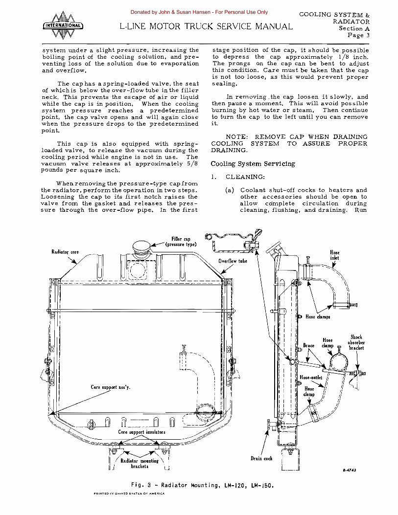
(a) Coolant shut-off cocks to heaters and other accessories should be open to allow complete circulation during cleaning, flushing, and draining. Run
~ ~
Sbock absorber bracket
.rv.~: Drain cockII ,I Radiator mounting \
ti J brackets U 8·4743
Fig. 3 - Radiator Mounting, LM-120, LM-J50. PRINTED IN UNITED STATES OF AMERICA
Donated by John & Susan Hansen - For Personal Use Only

COOLING SYSTEM & RADIATOR Section A L-LINE MOTOR TRUCK SERVICE MANUAL Page 4
the engine, with radiator covered if necessary, until temperature is up to operating range (160 0 F to 180 0 F). Stop engine, remOve radiator cap, and drain system by opening drain cocks in radiator and cylinder block.
(b) Allow engine to cool, clos e drain cocks, and pour cleaning compound into radiator according to directions. Fill system with water .
(c) Place a clean drain pan to catch overflow, and use to maintain level in radiator. Do not spill solution on vehicle paint.
(d) Replace radiator cap. and run engine at moderate speed, covering radiator if necessary, so that radiator core reaches a temperature of 1800
. F or above. but does not reach boiling point. Allow the engine to run at leas t two hours at 1800 F so that c'leaning solution may take effect. Do not drive vehicle or allow liquid level in radiator to drop low enough to interfere with circulation.
(e) Stop engine as often as necessary to prevent boiling.
(£) With the engine stopped, feel the radi-
FiBer cap Radiator core (pressure type)
\ \
Core support an'y.
ator core with bare hands to check for cold spots. and watch temperature gauge. When there is no change in temperature for some time, drain the cleaning solution.
(g) If clogging of core is relieved but not fully corrected, allow the engine to cool, pressure-flush the system (step 3 below), and repeat cleaning operation.
(h) If clogging of core, indicated by low temperature spots on core, is not relieved, radiator core mustbe removed for mechanical cleaning. Mechanical cleaning requires removal of upper and lower tanks and rodding out the accumulated rust and scale from the water passages of the core.
2, NEUTRALIZING:
(a) Allow engine to cool, close drain cocks, and pour neutralizer compound into radiator. Use as directed. Fill system with water.
(b) Run engine. with radiator covered if necessary, until radiator reaches operating temperature (l600 F to 180 0 F).
Brace (mounted on left side for L. H. drive, and on right side for R. H. drive)
Brace (mounted on right side for L. H. drive, and on left side for R. H. drive)
Fig. q - Radiator Mounting, L-150, L-153. L-ISO. L-IS3. L-ISq. L-165. LC-160.
11-4742
Donated by John & Susan Hansen - For Personal Use Only
COOLING SYSTEM &: RADIATORL-LiNE MOTOR TRUCK SERVICE MANUAL Section A
Page 5
(c) Drainthe systembyremoving radiator cap and opening drain cocks.
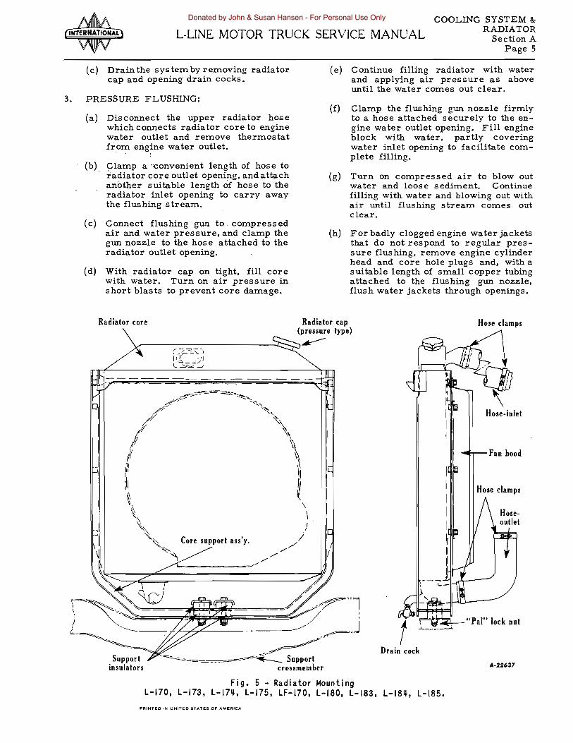
3. PRESSURE FLUSHING:
(a) Disconnect the upper radiator hose which connects radiator core to engine water outlet and remove thermostat from engine water outlet.
Clamp a "convenient length of hose to radiator core outlet opening, and attach another suitable length of hose to the radiator inlet opening to carry away the flushing stream.
(c) Connect flushing gun to _compressed air and water pressure, and clamp the gun nozzle to the hose attached to the radiator outlet opening.
(d) With radiator cap on tight, fill core with water. Turn on air pressure in short blasts to prevent core damage.
Radiator core
I I J
Support insulators
(e) Continue filling radiator with water and applying air pressure as above until the water COmes out clear.
(f) Clamp the flushing gun nozzle firmly to a hose attached securely to the engine water outlet opening. Fill engine block with water, partly covering water inlet opening to facilitate complete filling.
(g) Turn on compressed air to blowout water and loose sediment. Continue filling with water and blowing out with air until flushing stream comes out clear.
(h) For badly clogged engine water jackets that do not respond to regular pressure flushing, remove engine cylinder head and core hole plugs and, with a suitable length of small copper tubing attached to the flushing gun nozzle, flush water jackets through openings.
Hose·inlet I I I Fan hood
If-
Hose clamps
"Pal" lock nut
Drain cock
A·22637
Fig. 5 - Radiator Mounting L-170, L-173, L-17~, L-175, LF-170, L-180, L-183, L-18~, L-185.
PAINTED fN UNITED STATES OF AMERIC-.
Donated by John & Susan Hansen - For Personal Use Only

COOLING SYSTEM & RADIATOR Section A L-UNE MOTOR TRUCK SERVICE MANUAL Page 6
(i) When vehicle is equipped witha heater connected to the cooling system, flush the heater, following same procedure as for radiator core.
(j) After completing the flushing operation, clean out radiator overflow pipe, inspect the water pump, clean the thermas tat, and radiator cap control valves. Check thermostat for proper ope ration befor e ins talla tion. (See II Enginetl Section.)
(k) Blow ins ects and dirt from radiator core air passages, using water, if necessary, to soften obstructions.
4. LEAKS:
(a) Before pouring coolant into the cooling system a check should be made for leaks to avoid loss of solution, foaming and corrosion. Check tightness of cylinder head bolts, using tension wrench and tightening to specific number of foot-pounds with engine hot.
Radiator core
NOTE: After tightening cylinder head on valve-in..head engines it will be necessary to recheck valve stem clearance. Adjust, if necessary.
5. COOLANT SERVICE:
(a) Whe.n servicing for summer, fill system with clean water and add rust inhibitor compound. Use as directed.
(b) When servicing for winter, refill system with clean water and sufficient antifreeze solution for protection to lowest temperature likely to be encountered.
6. GENERAL INFORMATION:
(a) Never mix cleaning solution with inhibitor or antifreeze compounds.
(b) Before dismantling an engine preliminary to grinding valves, removing carbon, or rebuilding, always clean the cooling system first.
Radiator cap Hose-inlet /(pressure type)
~~~------~~------~~
Hose clamps
Fan hood
Hose clamps
Core support ass'y.
Support insulators
Fig. 6 - Radiator Mounting L-190, LF-190, L-193. L-19Q, L-195, L-200, L-20Q, L-205, L-210, LF-210.
A·22716
Donated by John & Susan Hansen - For Personal Use Only