cooling and cryocoolers for hts power...
TRANSCRIPT

APPLIED SUPERCONDUCTIVITY AND ELECTROMAGNETICS, Vol. 4, No. 1, November 2013 97
Abstract All the HTS electrical applications
require to be cooled down to operating temperature range of 20-77 K. The presentation provides a review of various coolants, cooling methods and the state-of-the- art cryocoolers. The major requirements of the cryo- coolers under developing are outlined. Some cryo- coolers application cases are also shown for the HTS FCL, transformers, cables, rotating machines and SMES.
Index Terms Cryocoolers, refrigerators, HTS power applications.
1. Introduction
The operating temperatures (Top) of HTS power applications are located in the range of 20 K – 77 K. The Top depends on the maximum magnetic field in superconductors and HTS type (Top of BSCCO tapes are required lower than YBCO’s for the same application). An overview of the respective required temperature range and cooling power level for the major power applications is shown in slide 4: transmission cables are cooled with forced flow of 67-77 K liquid nitrogen (LN2), and the heat load estimated is 3-5 kW/km [1], so the total heat loads for a set of 1 km cables achieves 15-20 kW at 65 K; FCLs and YBCO transformers are adopted bath cooling in 65-77 K LN2 [2,3], the cooling power are less than 2 kW at the 70 K; the rotating machines (motors/generators) operate at 25- 40K; the cooling power required is less than 800 W. The Top of BSCCO or YBCO SMES magnets are in 20-30 K range; the cooling power is from tens Watts to 1 kW for the storing energy from MJ to GJ.
The minimum power consumptions for a Carnot refrigeration cycle and real cycle of a cryocooler are shown in slide 5. The later is 3~10 times larger [1].
Liquid hydrogen can be used to cool MgB2 power cables or SMES [4] at Top~20 K when LH2 becomes a major energy to be transported. Neon is an ideal refrigerant in bath cooling for BSCCO rotating machines operating around 27 K [5,6], its latent heat of vaporization per volume is 40-time higher than liquid helium. Liquid neon (LNe) may be used as secondary cryogen for Top stability where the refrigeration is provided by helium based cryocoolers. Gaseous helium (GHe) is usual working refrigerant in cryocooler process, but it may also cool SMES and rotating machines operating in 20 K to 50 K.
Yanfang Bi is with Institute of Plasma Physics, Chinese Academy of Sciences, Anhui Provence, Hefei 230031, China (e-mail: [email protected]).
For BSCCO/YBCO cables, FCLs and transformers LN2 is the best coolant, which has perfect dielectric performance, safe chemical property, much cheaper cost than liquid helium, and can provide high cooling capacity. The coolants property are listed in slide 6 [7].
The cooling modes of bath, forced flow, conduction and thermosiphon are accepted for HTS power applications. Slide 7 lists the characteristics and applications. Two thermosiphon cooling samples for a HTS motor and the ALBANY cable [8] are shown in slide 8.
Cooling systems for HTS power applications can be classified into open and closed loops. In an open loop the bulk LN2 in a storage tank is brought from industry; it is transferred batch-wise to the application’s cryostat. The boiled off nitrogen is vented into atmosphere. The primary advantages of open-loop systems are relative simplicity of design and generally high reliability when LN2 supply is plentiful. If the boiling-off coolant re-condensed by a cryocooler or the application is directly connected to a cryocooler, the system is called closed loop. The open loop system can provide unlimited back-up refrigeration capability for the closed loop.
2. Cryocoolers
A cryocooler is the key equipment for a cooling system. Slide 9 lists the basic requirements. The high reliability is most important for electrical power applications. The low cryocooler cost will be met when massive production per year achieves.
2.1 Cryocooler Types
Slide 10 shows schematics of the five major types of refrigeration cycles. The Claude cycle combines the Brayton and the JT’s. Compression occurs at ambient temperature T0, with the compression heat dissipated to the ambient. Expansion occurs at the cold end at a temperature Tc, where the net refrigeration power Qc is absorbed. High- effectiveness heat exchangers are required to reach cryogenic temperatures [9]. JT cycle has a low efficiency, so it is mainly employed in small cryocoolers. Reverse- Brayton cryocoolers cover the widest cooling temperature range with largest capacity up to megawatts (see slide 4).
The three regenerative cycles shown in slide 10 operate with oscillating flows and oscillating pressures: which is alternately passed by warm high-pressure gas in one direction and subsequently by cold low-pressure gas in reversed direction. Frequencies vary from about 1 Hz for the Gifford-McMahon (GM) and some pulse-tube (PT) coolers to about 60 Hz for Stirling and some PT cryocoolers. The use of a displacer in the Stirling and GM
Cooling and Cryocoolers for HTS Power Applications
Y. F. Bi
Y. F. Bi: Cooling and Coolers for HTS Power Applications 98
cryocoolers moves most of the gas to the hot end during the compression process and to the cold end during the expansion process. In the PT cryocooler oscillating flow through the warm-end orifice moves the gas with a similar phase relationship as provided by a displacer, but without a moving part. Thus, the PT cryocooler has an inherent potential to be more reliable and have less vibration than either the Stirling or GM cryocoolers [9]. The use of valves in the GM cryocooler or with PTs driven with a GM-type compressor and rotary valve reduces their efficiency compared with valveless compressors used in the Stirling or Stirling-type PT coolers. However, the use of valves in the compression process provides a region of steady high pressure where an adsorber can be used in conjunction with a commercial oil-lubricated compressor in order to achieve high reliability. The regenerative heat exchanger used for these cycles has only one flow channel, which is filled with a porous matrix with high surface area, heat capacity and very compact. Heat is transferred from the ‘hot blow’ to the ‘cold blow’ via the matrix. Such heat exchangers are simple to make and are less expensive than recuperative type’s.
2.2 State-of-the-Art of Cryocoolers Two Stirling coolers [10, 11] and two GM coolers [12]
shown in Slide 11 are commercial available. High-power Stirling PT coolers driven by oil-free linear compressors are promising candidates to cool HTS devices as the advantages of simple configuration, low noise and stable operation [13]. Air Liquid Advanced Technologies (AL) has developed a 22 kW at 72 K refrigerator dedicated to long-length HTS cables [14] in slide 10. The main features are: high reliability, maintenance free, high efficiency (28% of Carnot) and stand alone packaged system. Using motor-turbo-expanders, the efficiency can reach a high value because useful work can be extracted from the refrigerant; especially if the turbo-compressors-motor and turbo-expanders operate on magnetic bearings, the reliability and MTBM will increase up to an expected level.
2.3 Cryocooler Application Cases
Slide 14 shows two 1 kW @ 77 K PT cryocoolers used for Columbus cable. GM cryocoolers applied for the rotating machines, transformer and small scale SMES are displayed in slide 15. The Stirling coolers are employed for the cables and FCL in slide 16.
The turbo-Brayton cryocoolers are used for cables of LIPA I and II in slides 17-19. The LIPA I cryogenic system occupies a big space [15]; but LIPA II system is very compact within a 40-feet transportation box [14].
3. Remarks Stirling cryocoolers can provide quite high cooling
capacity in 20-77 K range, high efficiency and lower cost, but shorter MTBT.
Using non-wearing pressure wave generator to drive Stirling-type PT coolers can be oil-free, thus maintenance free. The PT has no moving parts in the cold section, therefore very low vibration and high reliability, but its efficiency is lower than Stirling’s.
Single-stage G-M cryocoolers are the workhorses, reliable and higher efficiency than Stirling coolers in 20-35
K range. MTBM can reach more than 1-2 years. If Brayton cryocoolers consist of turbo-expanders and
turbo-compressors, the goal of oil-free, maintenance free, high efficiency and high cooling power can achieve for transmission cables; but more expensive.
Open-loop cooling system is simple, lower investment cost and reliable, but cumbersome for LN2 transportation and filling into the storage tank. The N2 vapor coldness from ~77 K to 300 K cannot be utilized. LN2 storage may be used as back-up cooling capacity and refrigeration, which is much cheaper than a redundancy cryocooler.
References [1] M. J. Gouge, J. A. Demko, J. M. Pfotenhauer, and B. W.
McConnell, Cryogenics Assessment Report, final version, ORNL and University of Wisconsin, May 2002.
[2] H. P. Kraemer, W. Schmidt, H. Cai, B. Gamble, D. Madura, T. MacDonald, J. McNamara, W. Romanosky, G. Snitchler, N. Lallouet, F. Schmidt, and S. Ahmed, “Superconducting fault current limiter for transmission voltage”, Physics Procedia, vol. 36, pp. 921-926, 2012.
[3] B. Schwenterly, and E. Pleva, HTS Transformer Development, Presented for U.S. DOE Peer Review Washington, DC, 30 June 2010.
[4] T. Shintomi, Y. Makida, T. Hamajima, S. Tsuda, D. Miyagi, T. Takao, N. Tanoue, N. Ota, K. Munakata, and Y. Miwa, “Design study of SMES system cooled by thermo-siphon with liquid hydrogen for effective use of renewable energy”, IEEE Transactions on Applied Superconductivity, vol. 22, no. 3, 5701604, June 2012.
[5] T. Zhang, K. Haran, E. T. Laskaris, and J. W. Bray, “Design and test of a simplified and reliable cryogenic system for high speed superconducting generator applications”, Cryogenics, vol. 51, pp. 380-383, 2011.
[6] B. Felder, M. Miki, K. Tsuzuki, N. Shinohara, H. Hayakawa, and M. Izumi, “A 100-W grade closed-cycle Thermosyphon cooling system used in HTS rotating machines”, Advances in Cryogenic Engineering, vol. 57, pp. 417-424, 2012.
[7] J. G. Weisend II, Handbook of Cryogenic Engineering, Taylor & Francis Ltd, London, 1999.
[8] R. C. Lee, A. Dada, and S. M. Ringo, “Cryogenic refrigeration system for HTS cables”, IEEE Transactions on Applied Superconductivity, vol. 15, no. 2, June 2005.
[9] R. Radebaugh, Cryocoolers: the state of the art and recent developments, Journal of Physics: Condensed Matter, vol. 21, p. 164219, 2009.
[10] http://www.stirlingcryogenics.com/products, 10/09/2012. [11] www.suzukishokan.co.jp/teion/pdf/pdf_teion_aisin.pdf, 10/09/
2012. [12] http://www.cryomech.com/gmcryorefrigerators.php, 11/09/
2012. [13] S. A. Potratz, T. D. Abbott, M. C. Johnson, and K. B. Albaugh,
“Stirling - type pulse tube cryocooler with 1kW of refrigeration at 77K”, Advances in Cryogenic Engineering: Transactions of the Cryogenic Engineering Conference, vol. 53, p. 985, 2008.
[14] A. Ravex, Refrigeration System Design, LIPA II Project DOE Peer Review Update, 29 June - 1 July 2010.
[15] S. Bratt, Refrigerator Status-Performance, LIPA II Project DOE Peer Review Update, 29-31 July 2008.
[16] H. K. Nathan, Cryogenic Refrigeration Costs and Prospects, Superconductivity Workshop UK, 23 October 2003.
[17] B. Gromoll, “Technical and economical demands on 25 K – 77 K refrigerators for future HTS – series products in power engineering”, Advances in Cryogenic Engineering: Transactions of the Cryogenic Engineering Conference, vol. 49, p. 710, 2004.
Presenter Yanfang Bi, Senior Researcher, currently the Consultant for Cryogenic Technology and Engineering Division in Institute of Plasma Physics, Chinese Academy of Sciences. Research interest mainly focuses on refrigeration for LTS magnets & HTS power applications. Principal contribution to the 2 kW @ 4.5 K cryoplant for EAST Tokamak and 10-68 kA HTS current leads for ITER.

Y. F. Bi: Cooling and Coolers for HTS Power Applications 99
Cooling & Coolers for HTS Power Applications
Yanfang BIInstitute of Plasma Physics, Chinese Acedemy of Sciences
CEGRE WG D1.38 Workshop on HTS for Utility Applications, Beijing 26.04.2013
CASIPP
Slide 1 Title of the presentation.
Slide 2 Contents.

Y. F. Bi: Cooling and Coolers for HTS Power Applications 100
Introduction• The operating temperatures (Top) of HTS electrical
power applications are located the range of 20–77 K.• Top depends on the max. magnetic fields within HTS
location. The higher mag. field requires the lower Top.• Liquids of Hydrogen, Neon, Nitrogen and some mixture
are popular coolants for HTS power applications.• Gaseous He and Ne are also used for cryocoolers in the
process.• The minimum power consumption of a cryocooler is based on the
coefficient of performance COPideal of Carnot cryogenic cycle:
• The lower Top consumes more power for refrigeration.• How much cooling power required depends on the heat
loads of the HTS power application.
c
ch
c
idealT
-TT
Q
WCOP == idealreal COP)10~3(COP ×=
1
Slide 3 Introduction.
Operating temp. & cooling power for HTS power applications & cryocoolers
�Top of 20K to 30K for SMES is the lowest. � The high cooling power is used for transmission cables up to a few tenth kilow-watts.
Slide 4 Operation temperature and power ranges for HTS power applications and cryocoolers.

Y. F. Bi: Cooling and Coolers for HTS Power Applications 101
20 30 40 50 60 70 800
50
100
150
200
CO
Pid
eal (
W/W
)
Top (K)
COPideal
COPreal, min
COPreal, max
Operating temperature (K), assume Th =303K 77 50 40 30 20
COPideal, (W input @303K per W lifted @Tc) 2.94 5.06 6.58 9.1 14.15
COPreal for >100 W heat loads
(W input@303K per W lifted@Tc)
~12-20 ~25-35 ~35-50 ~50-75 ~100-200
COPideal & COPreal vs Top
�Top reduction will result in cooling consumption increase.�Below 30 K COPreal increasing is very steep.
Slide 5 Ideal and real COP related with the operating temperature.
Coolants and property
• LH2 has the highest latent heat of vaporization and specific heat, but easy explosive. It can be used for large scale SMES and MgB2 transmission cables.
• LNe has the highest density and cost. It is able to cool rotating machines.• LN2 is the cheapest coolant, has perfect dielectric performance and safe
chemical property. It is very useful to cool cables, trasformers and FCLs, but its lowest Top is 63.5K only.
He H2 Ne N2
Normal boiling point at 1 bar (K) 4.22 20.27 27.09 77.36
Triple-point temperature (K) - 13.8 24.56 63.15
Latent heat of vaporization (kJ/kg) 20.9 443 85.9 199.3
Density of saturated liquid at 1 bar (kg/m3) 125 70 1206 807
Specific heat of liquid at 1 bar (kJ/kg/K) 5.47(GHe@20K) 9.48 1.94 2.04
Slide 6 The properties of the coolants used for HTS power applications.
(The data listed in the table refer to J. G. Weisend II’s book [7])

Y. F. Bi: Cooling and Coolers for HTS Power Applications 102
Cooling methods and loops• Bath cooling is very simple and effective, it can be used for
transformers, FCLs and SMES.
• Forced flow cooling requires a circulating pump, usually applied for transmmision cables.
• Thermosyphon cooling based on gravity difference betwen the coolant liquid and vapor can be used for rotating machines, subcooler for cables and small SMES.
• Conduction cooling is suitable for small scale SMES.
• Spray cooling LN2 is sprayed into the cable cryostat under testing.
• Open cooling loop has no cryocooler; the boiling-off coolant is not recirculated. It is applied for LN2 cooled transformers and FCLs.
• Closed cooling loop the coolant vapor re-condensed by a cryocooler, it used for cables, transformers, FCLs, rotating machines and SMES.
Slide 7 Overview of the cooling methods and loops for HTS power applications.
Two cases of thermo-siphon cooling
100 W @25K (Neon recodensed) provided by two GM coolers is used for a rotating machine.
Thermo-syphon cooling was used for ALBANY cable (34.5kV, 800A; 350 m long), the cooling capacity was 3.7 kW @70K, 5 kW @77K.
condenser cooled with He flow
Heat exchanger
LN2
Slide 8 Two cases of thermo-siphon cooling.
(The pictures refer to B. Felder’s and R. C. Lee et al’s papers [6,8])

Y. F. Bi: Cooling and Coolers for HTS Power Applications 103
Cryocoolers requirements for HTS power applications
� Low operation cost:� High efficiency, the goal to achieve 30% Carnot
� Low maintenance, MTBM (Mean Time Between Maintenances) should be longer than 2.5~3 years.
� Low cryocooler cost, (the goal is from ~100 to 25 US$/W @ ~65-80K)
� High reliability, The HTS power component itself requires 99.8-99.9 % availability, this means the cryogenic subsystem needs 99.9% and higher reliability.
� Long life time
Now there is no any cryocooler able to meet above requirements (proposed by USA experts in 2003).
Slide 9 Cryocoolers requirements for HTS power applications.
(The requirements refer to a M. J. Gouge et al’s report [1])
Cryocooler types•The Joule-Thomson (JT) and turbo-Brayton cycles are classified as recuperative cycles, in which there are two steady gas flows with steady low and high pressures.•JT coolers have lower efficiency, but relaiable due to no moving components.•Turbo-Brayton coolers cover the widest Top and cooling capacity, but expensive.•Stirling coolers have regenerator and displacer, posses the highest efficiency, larger unit cooling capacity and lower cost, but shortest maintain period (≦7000hrs). •Pulse tube coolers have no moving parts, resulte in the longest life, but the efficiency is not as high as Stirling coolers for cooling capacity ≧1kW @77K coolers.•GM coolers have a rotatong control valve, which results in efficiency reduced; but oil lubricated compressors can be employed and provide quite long maintenance period and good reliability.
Slide 10 Overview of different type cryocoolers.
(The right picture refers to R. Radebaugh’s paper [9])
Y. F. Bi: Cooling and Coolers for HTS Power Applications 104
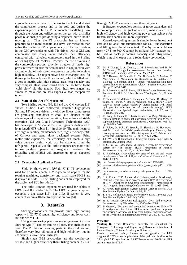
State-of-the-art cryocoolers
22 kW@72K turbo-Brayton cooler for LIPA II cables & FCLs made by AL
Turbo-motor-cmpressor
NIST 500 W@30K Stirling-PT cooler
AISIN SEIKI 1 kW@77K Stirling cooler SC1501
Stirling C&R SPC-4, 4 kW@80K GM & GM-PT coolers made by CRYOMECH
PT90AL600
Cold headCompressor
Slide 11 The state-of-the-art for the typical cryocoolers.
(The Stirling and GM cryocoolers pictures from the webs of Stirling C&R, AISIN SEIKI and CRYOMECH companies [10-12]. The other cryocoolers are under developing, so not commercial available [9,14])
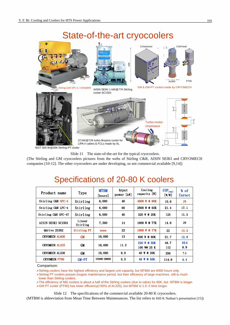
Specifications of 20-80 K coolers
Product nameProduct nameProduct nameProduct name TypeTypeTypeTypeMTBMMTBMMTBMMTBM[hours][hours][hours][hours]
Inputnputnputnputpowerpowerpowerpower [kW][kW][kW][kW]
Cooling Cooling Cooling Cooling capacity [W]capacity [W]capacity [W]capacity [W]
COPCOPCOPCOPrealrealrealreal
[W/W][W/W][W/W][W/W]
% of % of % of % of CarnotCarnotCarnotCarnot
Stirling C&R Stirling C&R Stirling C&R Stirling C&R SPCSPCSPCSPC----4444 StirlingStirlingStirlingStirling 6,0006,0006,0006,000 40404040 4000 W @ 80K4000 W @ 80K4000 W @ 80K4000 W @ 80K 10.010.010.010.0 28
Stirling C&R LPCStirling C&R LPCStirling C&R LPCStirling C&R LPC----4444 StirlingStirlingStirlingStirling 6,0006,0006,0006,000 60606060 2800 W @ 65K2800 W @ 65K2800 W @ 65K2800 W @ 65K 21.421.421.421.4 17.117.117.117.1
Stirling C&R SPCStirling C&R SPCStirling C&R SPCStirling C&R SPC----4T4T4T4T StirlingStirlingStirlingStirling 6,0006,0006,0006,000 40404040 320 W @ 20K320 W @ 20K320 W @ 20K320 W @ 20K 125125125125 11.311.311.311.3
AISIN SEIKI SC1501AISIN SEIKI SC1501AISIN SEIKI SC1501AISIN SEIKI SC1501Linear Linear Linear Linear
StirlingStirlingStirlingStirling7,5007,5007,5007,500 14141414 1000 W @ 77K1000 W @ 77K1000 W @ 77K1000 W @ 77K 14.014.014.014.0 20
Qdrive 2S362Qdrive 2S362Qdrive 2S362Qdrive 2S362 Stirling PTStirling PTStirling PTStirling PT nonenonenonenone 22222222 1000 W @ 77K1000 W @ 77K1000 W @ 77K1000 W @ 77K 22222222 13.313.313.313.3
CRYOMECH CRYOMECH CRYOMECH CRYOMECH AL600AL600AL600AL600 GMGMGMGM 10,00010,00010,00010,000 13131313 600 W @ 80K600 W @ 80K600 W @ 80K600 W @ 80K 21.721.721.721.7 12.912.912.912.9
CRYOMECH CRYOMECH CRYOMECH CRYOMECH AL325AL325AL325AL325 GMGMGMGM 10,00010,00010,00010,000 11.211.211.211.2230 W @ 50K230 W @ 50K230 W @ 50K230 W @ 50K
100 W@ 25 K100 W@ 25 K100 W@ 25 K100 W@ 25 K
48.748.748.748.7
112112112112
10101010.4444
9.99.99.99.9
CRYOMECH AL330CRYOMECH AL330CRYOMECH AL330CRYOMECH AL330 GMGMGMGM 10,00010,00010,00010,000 8.08.08.08.0 40 W @ 20K40 W @ 20K40 W @ 20K40 W @ 20K 200200200200 7.1
CRYOMECH CRYOMECH CRYOMECH CRYOMECH PT90PT90PT90PT90 GMGMGMGM----PTPTPTPT 15000150001500015000----20000200002000020000 5.55.55.55.5 48 W @ 50K48 W @ 50K48 W @ 50K48 W @ 50K 114.6114.6114.6114.6 4.44.44.44.4
�Stirling coolers have the highest efficiency and largest unit capacity, but MTBM are 6000 hours only.�Stirling PT coolers posses longest maintenance period, but their efficiency of large machines still is much
lower than Stirling coolers.�The efficiency of MG coolers is about a half of the Stirling coolers (due to valve) for 80K, but MTBM is longer.�GM PT cooler (PT90) has lower efficiency(<50% of AL325), but MTBM is 1.5~2 time longer.
Comparison:
Slide 12 The specifications of the commercial available 20-80 K cryocoolers.
(MTBM is abbreviation from Mean Time Between Maintenances. The list refers to Hill K Nathan’s presentation [15])

Y. F. Bi: Cooling and Coolers for HTS Power Applications 105
Comparison of coolers cost(2004-year data, but recently change not too much)
Slide 13 Comparison of cryocoolers costs.
(The list refers to B. Gromoll’ paper [16])
Cases of open cooling loop
220kV/800A SFCL developed by Innopower
Columbus cable was cooled with an open-loop vacuum cryogenic system in 2006. Two pulse tube coolers (from Praxair) were added in 2008.
1 kW @ 77K Stirling-PT cooler
35kV/1.5kA SFCL at Puji station
Slide 14 Three cases of the open cooling loops. (The right two pictures refer to S. A. Potratz et al’s paper [13])

Y. F. Bi: Cooling and Coolers for HTS Power Applications 106
Cryocooler applications
One GM cooler is applied for 1MW HTS motor of Korea Electrotechnology Research Institute.
Two GM cryocoolers are used for SIEMENS 4 MVA BSCCO-HTS synchronous generator at 3600 rpm (in blue), the HTS race-track coils are operated around LNe temperature.
Four GM coolers provide conduction cooling for 2.5 MJ SMES HTS coils designed by S. Kwak, Korea.
GM cooler is used for HTS transformer designed
by ORNL Bill Schwenterly in 2010.
Slide 15 GM cryocoolers used for the HTS generator, motor, transformer and SMES. (The pictures refer to Google’s HTS application web site)
Cryocooler applications cont.
35kV/2kA HTS cables cooled with seven AL300 GM coolers in Puji power station
Two Stirling coolers are employed for 154 kV Korea HTS cable in DAPAS.
Two SPC-1 Stirling coolers are used for FCL
Slide 16 The cryocoolers used for the HTS cables and FCL. (The Stirling cooler applications refer to Google pictures web site)

Y. F. Bi: Cooling and Coolers for HTS Power Applications 107
Cryogenic system for LIPA IThe system consists of a turbo Brayton refrigerator and a backup cooler (a pumped LN2 vessel). The total capacity can reach 8.1 kW @ 65.3~70.5 K.
Slide 17 Cryogenic system flow diagram for the LIPA I cable.
(The picture refers to S. Bratt’s presentation [17])
Major cryogenic equipment for LIPA I
Distribution box LN2 storage tank2 He compressors
Cold box made by Linde before 2000
Cryogenic system room
�The coldbox of cryogenic system for LIPA I was made by Linde, has cooling power of ~4 kW @65-70 K, which is not enough to support the cable operating at higher urrents. A backup cooler is required.�The whole system occupys a big space.�The cryocoolers have a lower efficiency due to the screw compressors (51%), oil remover and many control valves.
Cryogenic system for LIPA I cont.
Slide 18 The major cryogenic equipments for the LIPA I cable.
(The pictures refer to S. Bratt’s presentation [17])
Y. F. Bi: Cooling and Coolers for HTS Power Applications 108
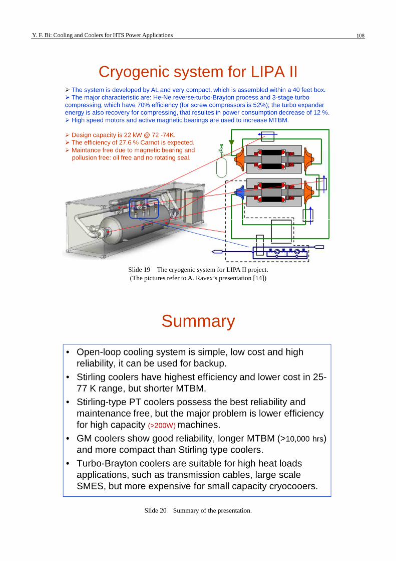
Cryogenic system for LIPA II� The system is developed by AL and very compact, which is assembled within a 40 feet box.� The major characteristic are: He-Ne reverse-turbo-Brayton process and 3-stage turbo compressing, which have 70% efficiency (for screw compressors is 52%); the turbo expander energy is also recovery for compressing, that resultes in power consumption decrease of 12 %.� High speed motors and active magnetic bearings are used to increase MTBM.
� Design capacity is 22 kW @ 72 -74K.� The efficiency of 27.6 % Carnot is expected.� Maintance free due to magnetic bearing and
pollusion free: oil free and no rotating seal.
Slide 19 The cryogenic system for LIPA II project. (The pictures refer to A. Ravex’s presentation [14])
Summary
• Open-loop cooling system is simple, low cost and high reliability, it can be used for backup.
• Stirling coolers have highest efficiency and lower cost in 25-77 K range, but shorter MTBM.
• Stirling-type PT coolers possess the best reliability and maintenance free, but the major problem is lower efficiency for high capacity (>200W) machines.
• GM coolers show good reliability, longer MTBM (>10,000 hrs)and more compact than Stirling type coolers.
• Turbo-Brayton coolers are suitable for high heat loads applications, such as transmission cables, large scale SMES, but more expensive for small capacity cryocooers.
Slide 20 Summary of the presentation.