convex (continuously varied ... - unconstrained design
TRANSCRIPT

1
CONVEX (CONtinuously Varied EXtrusion): a new scale of
design for additive manufacturing
Amirpasha Moetazediana, Anthony Setiadi Budisuhartob, Vadim V. Silberschmidta and Andrew
Gleadalla*
a Wolfson School of Mechanical, Electrical and Manufacturing Engineering, Loughborough
University, Loughborough, LE11 3TU, UK
b Department of Materials Science and Engineering, City University of Hong Kong, Hong Kong,
83 Tat Chee Avenue, Kowloon 999077, Hong Kong Special Administrative Region, China
*Corresponding author - Email: [email protected]; Tel: +441509 227578
Abstract
This study introduces a new microscale design approach, CONVEX, based on the idea of
CONtinuously Varying EXtrusion widths of deposited filaments in material extrusion additive
manufacturing (MEAM). The CONVEX design approach breaks free from the traditional 3D
printing workflow of filling a CAD-model volume with stacked extruded filaments of a constant
width and height. Instead, the geometry of each filament is explicitly designed over its entire
length. The concept may disrupt a wide range of applications in both the short and long term.
In the least ambitious short-term implementation of CONVEX, its principles can be integrated
into 3D printing slicing software to allow a geometric form to be fitted by streamlined filaments,
with constantly varying widths as required to match the overall geometry (referred to as
“streamlined slicing”). The use of continuous streamlined filaments, as opposed to frequently
changing the number of filaments, improved the quality of manufactured parts by eradicating
voids and defects that are generated by staggered nozzle movement and discontinuous
printing. Such defects are known to cause critical stress concentrations in specimens for
tensile testing. At the other end of the scale, in the most disruptive implementation of the
CONVEX design approach, entire new material structures and product types will be enabled,
with feature size-scales perhaps an order of magnitude lower than that permitted by present
design rules. This will enable new innovative metamaterials and is particularly appropriate for
high-value applications such as advanced filtering, tissue engineering, drug delivery,
microfluidics or electronics, where the geometries of individual extruded filaments (or
deliberate inter-filament pores) form the functional design geometry. To rigorously prove the
technical feasibility of CONVEX, this study includes extensive experimental work that
parametrically investigates how instantaneous changes to MEAM process parameters (e.g.
2
speed, acceleration, extrusion rate and retraction) enable highly controllable and dynamic
variation of the width of extruded filaments (from 75% to 250% of nozzle diameter). The
concept is proven for multiple materials, layer heights, extrusion temperatures, nozzle sizes,
and for both Bowden and direct drive printer-types. The new understanding developed through
these fundamental characterisations is implemented in case studies for the CONVEX design
approach, which has already enabled break-through micro-mechanical research for MEAM.
Industrial implications of CONVEX are discussed along with the immediate potential for its
translation to other manufacturing processes.
Keywords: additive manufacturing; metamaterials; microscale design; Bowden tube; sub-
filament design.
Nomenclature:
ABS - Acrylonitrile butadiene styrene
AM - Additive manufacturing
CAD - Computer-aided-design
CONVEX - CONtinuously Varied EXtrusion design approach
EFW - Extruded-filament width
FFF - Filament fused fabrication
FDM - Fused deposition modelling
MEAM - Material extrusion additive manufacturing
PEEK - Polyetheretherketone
PLA - Polylactide
PCL - Polycaprolactone
ROI - Region of interest
ΔWs - Disruption of EFW (magnitude change) in response to instantaneous changes in a
printing parameter.
ΔWr - Recovery of EFW after an imbalance is introduced - typically caused by a mismatch
between the current extrusion pressure and the extrusion pressure required to achieve the
desired extrusion rate.
Ds - Normalised distance for a magnitude change in EFW in response to instantaneous change
in printing parameter.
Dr - Normalised distance for recovery of EFW.

3
1 Introduction
Additive manufacturing (AM) technologies have shown rapid and consistent development due
to their ability to facilitate fast product development and produce structures and metamaterials
that are not possible with conventional subtractive manufacturing processes [1], [2].
Consequently, the popularity of AM has grown in a range of sectors [3]–[6]. In particular, the
affordability and material-versatility of material extrusion additive manufacturing (MEAM) - also
known as fused filament fabrication (FFF) or fused deposition modelling (FDM) - resulted in
its use for a variety of applications such as biomedical, automotive and aerospace [2], [7]–[9].
Many thermoplastic polymers are currently being used in MEAM, including acrylonitrile
butadiene styrene (ABS), polylactide (PLA), polyamide (nylon), polycaprolactone (PCL) and
polyether-ether-ketone (PEEK) [10]–[15]. Importantly, this technology allows the production of
complex and intricate parts, metamaterials and structures that are not possible with injection
moulding or other conventional manufacturing processes [16], [17].
MEAM of thermoplastic polymer is achieved by depositing material onto the print platform
layer-by-layer. The process starts with feeding the filament into a melt chamber, set above the
melting point of the polymer, via a feeding mechanism consisting of rollers and gears (Figure
1). The molten polymer is then extruded through a nozzle onto the print platform [3]. The
nozzle’s print path defines the physical embodiment of the designed part or structure; typically,
one layer of a product is produced by moving the nozzle in the x/y directions (Figure 1) before
incremental movement of the print platform in the z direction. The typical workflow for
production of a 3D-printed part using MEAM involves: (i) generation of a three-dimensional
(3D) model of the design; (ii) converting the 3D model into an STL format; (iii) importing the
file into slicer software to generate the print path; (iv) saving the file as a series of machine
control commands (G-Code) and (v) printing the part layer-by-layer.
MEAM 3D printers can be categorised into two main types based on their feeding mechanism:
(a) direct drive and (b) Bowden tube (Figure 1) [18]. In both systems, the role of the feeding
mechanism is to push the filament into the melt chamber and generate the pressure required
to extrude the material through the nozzle. For direct drive systems (Figure 1a), the feeder is
attached directly above the printhead. In Bowden printers (Figure 1b), the feeding mechanism
is placed on the frame of the 3D printer, which means that the filament is pushed through a
Bowden tube as show in Figure 1b. In this setup, the distance from the feeder to the nozzle is
greatly increased (potentially ten times longer) by comparison to direct drive printers [18].
Therefore, Bowden printers can suffer from unresponsiveness: for instance, when the
extrusion rate changes in the G-Code, there may be a lag before a change to the physical
extrusion rate from the nozzle.

4
Figure 1 Schematic indicating the difference between direct drive (a) and Bowden (b) 3D
printers. Direct drive systems have a shorter distance from feeding mechanism to the nozzle
but a heavier printhead assembly.
Most studies in the literature [19]–[22] focused on the effect of printing parameters on the
mechanical performance or surface quality of 3D-printed parts. In contrast, there are limited
studies investigating the effect of different parameters on the actual geometry of single
extruded filaments [11], [16]. This is partially due to the traditional 3D printing workflow of using
computer-aided-design (CAD) to design the part and then employing slicing software to adjust
the printing parameters [23]. This approach limits the potential to have a full control over the
printing process and print path. A few studies [11], [15], [16], [24], [25] used in-house software
to directly control the 3D printing process and clearly demonstrated the benefit of this
approach. For example, Geng et al. [11] found the print speed to significantly affect the
microstructure and dimensions of extruded PEEK filaments. Barrios and Romero [26] showed
that acceleration influenced the surface roughness of 3D-printed parts. However, current
studies investigating the geometry of extruded filaments considered steady-state printing

5
conditions; there was no investigation into the effect of instantaneous changes of print
parameters such as speed or extrusion rate on filament geometry along its length. The current
study investigates for the first time the dynamic changes of the filament geometry in response
to a range of important control parameters available during the 3D printing process, including:
print speed, extrusion rate, retraction/un-retraction, acceleration and jerk. Furthermore, the
important influence of the feeding system design (direct drive versus Bowden) is investigated.
The need for this new understanding spans a range of fields from high-performance
applications to new lattice-like structures or metamaterials, where geometry at the scale of
single-filaments or smaller, without defects, is important [27]–[29]. The existing print path
strategies do not allow the full potential of 3D printers to be realised since they consider each
extruded filament to have a constant width, and the part is effectively filled by positioning
filaments side by side (or according to the chosen infill pattern).
Here, new understanding is developed for dynamic filament geometry (first three results
sections) to support a new design approach called CONVEX (CONtinuously Varied
EXtrusion), in which the widths of individual extruded filaments are designed to vary over their
length (final results section). Case studies show how the CONVEX approach enables (i) new
printpath-generation algorithms (for larger parts) or (ii) an entirely new scale of structural
design (for intricate structures), which has ground-breaking potential for a wide range of fields,
as already demonstrated by the CONVEX approach enabling technical breakthroughs in
process and material understanding [30]. This study demonstrates the potential for a step-
change in design capabilities and paves the way for a new generation of 3D printed
metamaterials and structures. The versatility of the suggested concept is demonstrated by
investigating different thermoplastic polymers (PLA, ABS and nylon), extrusion temperatures,
layer heights and feeder mechanisms. The potential of the CONVEX design approach for
industrial applications and other manufacturing processes is discussed.
2 Materials and methods
This section presents the CONVEX design approach and the method used to characterise
dynamic process capabilities.
2.1 CONVEX design approach
The CONVEX design approach is based on designing at the sub-filament scale by varying the
geometry of individual filaments along their length, as opposed to the conventional approach
utilising filaments with a constant cross-section.
By arranging extruded filaments with a constant cross section to fill a CAD-model volume (a
dogbone specimen for tensile testing is used for demonstration purposes), the discrete change

6
in the number of filaments limits the design resolution and introduces defects/pores (Figure
2a), which were shown to act as critical stress concentrators for a range of print-path designs
[31], [32]. Adding so-called “perimeters” to the print path does not solve the problem; it simply
shifts the defects from the surface to internal regions. Using the CONVEX design approach,
streamlined filaments can be designed with a deliberate continuously varying width to fit the
dogbone geometry, as shown in Figure 2b, eliminating voids/defects. Aside from improving
the manufacturing quality, the CONVEX design approach also enables completely new design
opportunities below the length-scale of individual filaments (e.g. to develop new structures and
metamaterials). As an example, the conventional design of tissue engineering scaffolds or
similar structures uses log-pile stacking of filaments with unvarying geometry (Figure 2c).
Therefore, the pores between the extruded filaments are of a constant size. Using the
CONVEX design approach, each filament has a designed continuously varying width to
achieve full control over the spatial distribution of pores with different dimensions. A simple
grading is shown in the schematic in Figure 2d; obviously, the pore size could be adjusted in
any manner, based on a greyscale image for example, which would not be possible by simply
changing the filament spacing in a conventional design. The CONVEX approach has already
been used to design a new micro-tensile-testing specimen with varying extruded filament width
(EFW), which allowed the development of new fundamental understanding of micromechanics
in AM [30], [33]. The next sections describe the parametric experimental investigation of how
printing parameters can be adjusted to achieve the CONVEX approach from a technical
viewpoint.
2.2 Parametric test-specimen design
A custom design (Figure 3) was developed to analyse the effect of systematically varying a
single parameter. In-house software (“FullControl GCODE Designer” - available from the
corresponding author) was used to generate G-Code files for printing a 10-layer stack of single
filaments. The print path is shown in Figure 3a (indicated by arrows). To normalise the
extrusion pressure after each line of print, a stabiliser line was used. The process was
repeated 10 times (offset in y direction) to achieve a series of specimens in the region of
interest (ROI - dashed box in Figure 3b). Each extruded filament was produced with three
sections: sections 1 and 3 (10 mm long at the beginning and end) and section 2 (40 mm long
in the middle) as shown in Figure 3c. Section 2 was printed with different printing parameters
(e.g. print speed) compared to sections 1 and 3 to characterise the dynamic response of EFW.
Figure 3c exemplifies the variation of the filament width in reponse to printing parameters: in
that example, section 2 was printed at a faster speed than sections 1 and 3, resulting in less
time for material deposition and, therefore, a narrower EFW.

7
Figure 2 CAD models exemplify the CONVEX design approach. Designs for tensile test
specimens and scaffold structures are shown for a conventional approach (a and c) and the
CONVEX design approach (b and d) in which the geometries of individual filaments are
deliberately designed to achieve previously impossible structures.

8
Figure 3 (a) Schematic of the design showing the nozzle’s print path (red arrows) for analysis
of the effect of gradually changing a single printing parameter. Each line is followed by a
stabiliser line to normalise the extrusion pressure. (b) Image of the final 3D-printed part
highlighting the region of interest (ROI) used to characterise the filament geometry. (c) Optical
micrograph showing the change in the extruded filament width across three sections.
2.3 Materials and 3D printing setup
The testing design defined in Section 2.2 was printed using a Raise3D Pro2 (Raise3D®, USA)
system as a representative for direct drive printers. The printer manufacturer’s polylactide was
used (Rasie3D® Premium PLA); with the printing parameters kept as default unless changed
as shown in Table 1. The nozzle deposited a single filament as defined in Section 2.2 using
either a constant nominal width across all three sections or different widths (e.g. sections 1
and 3 widths two times larger than section 2). Both design regimes were employed to
characterise the effect of various printing parameters on the extruded filament’s geometry,
which are described in detail in Section 2.4. A 0.4 mm nozzle was used with extrusion
temperature 205°C and layer height 0.2 mm.
To investigate the difference between direct drive and Bowden tube printers, an Ultimaker 2+
(Ultimaker®, Netherlands) was used to represent latter systems. As with former one, the printer
manufacturer’s polylactide was also used (Ultimaker® PLA) to print the same designs as those
printed by the direct drive system (defined in Section 2.2).
To investigate the transferability of results to other materials, an alternative PLA supplier
(3DXTECH®) and two alternative common polymers were used: ABS (3DXTECH®) and nylon
(NOVAMID, PA6/66).

9
2.4 Investigation of individual printing parameters
The printing parameters investigated in this study are listed in Table 1, which also indicates
the respective results section for each parameter. In each case, EFW was measured along
the length of the filament and its variations were analysed with respect to the instantaneous
changes in print parameters (e.g. print speed).
2.4.1 Print speed
To investigate the effect of the print speed (nozzle’s movement in the direction of printing) on
EFW, it was set to change from low to high and back to low in sections 1, 2 and 3, respectively,
in (Figure 3c). The speed was always 1.0 m.min-1 in sections 1 and 3 and ranged from 1.0 to
6.0 m.min-1 in section 2 (increments of 0.5 m.min-1). Acronyms were used to refer to each
design in this study. The naming method was as follows: printing parameter (e.g. print speed)
of section 1-section 2-section 3. For instance, to refer to samples with a print speed of 1.0
m.min-1 in sections 1/3 and 4.0 m.min-1 in section 2, the acronym 1.0-4.0-1.0 was used.
2.4.2 Acceleration and jerk
Based on obtained results for the print speed (Subsection 2.4.1), a reference speed of 3.0
m.min-1 for section 2 was employed with a range of accelerations to investigate the effect on
the dynamic response of EFW. The default acceleration setting for many printers is between
2.0 and 5.0 m.s-2 [18]; thus a broad range of acceleration was selected (0.05 to 6.0 m.s-2).
The effect of “jerk”, which refers to an instantaneous variation in velocity, was investigated for
3.0 m.min-1 print speed in section 2 and 0.50 m.s-2 acceleration. Typical jerk speeds are
between 0.015 and 0.200 m.s-1; so a wide range from 0.008 to 0.800 m.s-1 was used.
2.4.3 Retraction
Another variable that significantly influences extrusion, is “retraction” (i.e. pulling material back
into the nozzle). For the concepts discussed here, retraction (and un-retraction) may be useful
to achieve sudden changes to EFW. Retraction was applied at the beginning of section 2 of
specimens and was accompanied by un-retraction at the end of section 2 to ensure that the
same volume of material was extruded overall. A broad range of retraction values were used
(0.02 to 0.20 mm for direct drive; 2 to 20 mm3 for Bowden). These ranges were chosen
because they were either found in preliminary tests to be suitable for changing EFW by more
than required for the purposes of this study (direct drive), or because they considered a greater
range than typically used (Bowden).
2.4.4 Extrusion temperature and layer height
To investigate the influence of extrusion temperature, the experiments for speed and retraction
(Sections 2.4.1 and 2.4.3) were repeated at lower and higher temperatures than the reference

10
temperature (195°C and 215°C versus 205°C, respectively) for both direct drive and Bowden
printers. This was done to investigate the sensitivity of findings and to demonstrate the
resilience and transferability of the CONVEX approach to different printing conditions. Further
to this, specimens were printed with lower layer height (0.1 mm versus reference 0.2 mm).
2.5 Case studies
Three case studies were used to demonstrate the CONVEX design approach versus a
traditional 3D printing approach (CAD model > slicer software > G-Code > 3D print). For the
traditional approach, Cura software was used to slice the CAD models and generate G-Code.
For the CONVEX approach, in-house software (“FullControl GCODE Designer”) was used to
design the print path with explicit control over settings such as speed, extrusion rate and
acceleration. Extrusion temperature was 205°C and layer height was 0.2 mm. The printing
quality of both methods were compared using a Zeiss Primotech optical microscope. Cura
was used in this study because it is a powerful and well-respected slicer; the authors believe
no alternative slicing software would be able to achieve better results for the structure sizes
considered here. However, slicing software could be revised in the future to implement the
CONVEX approach. A video of the third case study is supplied as supplementary information.
2.6 Image processing
After printing, a SmartScope Flash 200 microscope (OGP, US) was used for dimensional
measurements. An optical image was captured every 4.25 mm for each testing line to yield 14
images per specimen (Figure 4a and b). A MATLAB script was developed to post-process the
data. All images were binarised and stitched together (Figure 4c and d). Then, white pixels
were counted to generate a plot of EFW versus distance. EFW was normalised by the initial
width (beginning of Section 1). Distance was normalised by the nozzle diameter (0.4 mm).

11
Table 1 List of parameters used to assess the change in the geometry of single extruded filaments for direct drive and Bowden printers. The first
section of results and discussion (Section 3.1; denoted as A) covers the response of the direct drive printer to the change in speed and retraction
for constant and varied EFW. The second part (Section 3.2; denoted as B) focuses on the comparison between direct drive and Bowden printers
for a range of parameters. In the third section (Section 3.3; denoted as C), the transferability of results to other materials and layer heights was
studied. In the last section (Section 3.4; denoted as D), the applicability of the results was shown by presenting three case studies. Bold italic
sections indicate the parameters that were the main focus for the respective row of the table.
Parameter
Normalised target width Print speed (m.min-1) Retraction for
section 2 Material
Temperature Acceleration Layer height
Section 1
Section 2
Section 3
Section 1
Section 2
Section 3
(mm for direct drive & mm3 for Bowden)
(°C) (m.s-2) (mm)
Speed 1 1 1 1 1-6 1
0
PLA
205 0.5 (direct
drive) & 3.0 (Bowden)
0.2
1 0.5 1 1 1-6 1
Retraction
1 1 1 1 1 1 0.02-0.2 (direct
drive) &
1 0.5 1 1 1 1 2.0-20.0 (Bowden)
Temperature
1 0.5 1 1 1-6 1 0 195, 205 and
215
1 0.5 1 1 1 1
0.02-0.2 (direct drive)
& 2.0-20.0 (Bowden)
Acceleration 1 0.5 1 1 3 1
0
205 0.05-6.0
Material 1 0.5 1 1 1-6 1
PLA 205
0.5 (direct drive)
ABS 240
Nylon 240
Layer height 1 0.5 1 1 1-6 1 PLA 205 0.1-0.2
Case studies
A
B
C
D
12
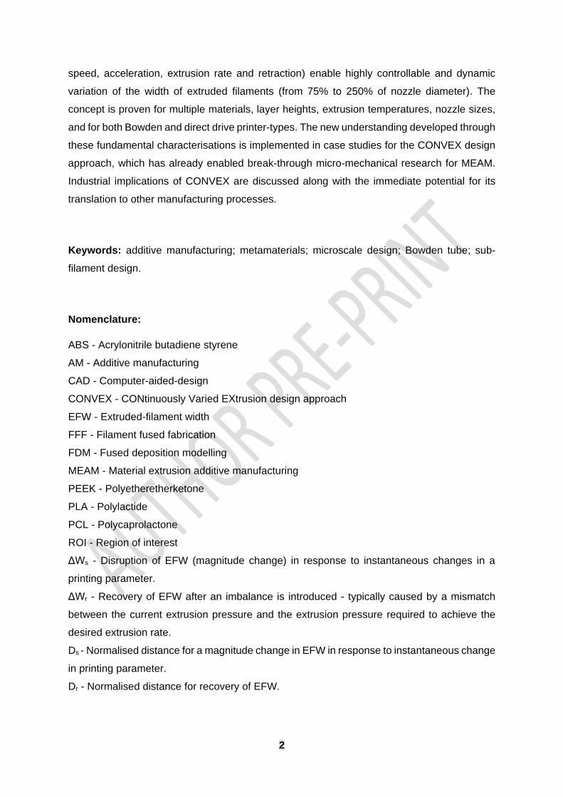
Figure 4 Schematic diagram indicating the workflow for measuring EFW. (a-b) Optical
microscopy images were taken every 4.25 mm to yield 14 images per specimen. (c-d) A
MATLAB script was used to binarise the images and (e) the number of white pixels were
counted to determine EFW and its variation with distance.
2.7 Quantitative analysis of dynamic change in EFW
Two different modes of transition from wide to narrow EFW (and vice versa) between the three
sections of specimen were identified:
• Transition mode I: associated with a sudden change in the normalised EFW, in
response to instantaneous changes in a printing parameter (e.g. print speed). The
change in width for this disruption is denoted as ΔWs throughout this study (Figure 5).
• Transition mode II: associated with natural recovery of EFW to the target EFW. The
change in width for recovery is denoted as ΔWr (Figure 5). Natural recovery occurs if
the target width is changed, as the extrusion process takes time to reach the new
steady state. In addition, the natural recovery occurs after a sudden disruption
(transition mode I), when the extrusion process returns to the original width before
disruption.
The potential combinations of transition modes I and II are shown in Figure 5. When the target
width is kept constant, but the steady-state nature of the printing process is interrupted by an
instantaneous change in a printing parameter, there is a sudden change in EFW followed by
a natural recovery (Figure 5a). When the target width of a filament is changed, but no other

13
printing parameters are varied, the steady-state is interrupted and there is a gradual recovery
to the new target EFW (Figure 5c). When the target width is changed in combination with
another printing parameter, there is a combination of a sudden change to EFW and a natural
recovery to the new target EFW (Figure 5b). The gradient and magnitude of the sudden
change and the natural recovery were calculated to allow quantitative analysis. To minimise
the effect of minor experimental errors or fluctuations, the distance to achieve 95% of target
EFW was considered for all quantifications.
Figure 5 Schematic diagrams indicating different possibilities for quantitative characterisation
of changes to EFW. (a) The nominal EFW remains constant but an instantaneous change to
a printing parameter results in a sudden change in EFW (“transition mode I” - quantified by
∆Ws) followed by a gradual recovery back to the target EFW (“transition mode II” - quantified
by ∆Wr). (b) Similar to (a) but combined with a change to the target EFW. (c) No printing
parameters are changed except the target EFW, which is gradually approached as pressure
in the nozzle naturally recovers towards the pressure required for steady-state printing at the
new EFW. The arrow by the nozzle schematic indicates printing direction.

14
3 Results and Discussion
The results and discussions are separated into four sections, as mapped out in Table 1:
• 3.1 – The dynamic response of EFW to changes in speed and retraction is investigated
for the direct drive printer.
• 3.2 – The responses are compared for the direct drive and Bowden printers for a range
of factors including speed, retraction, temperature and acceleration.
• 3.3 – Transferability and resilience of results are investigated in relation to material and
layer height.
• 3.4 – Case studies utilise the new understanding, developed in Sections 3.1-3.3, to
demonstrate the CONVEX design approach to produce structures that are not possible
with conventional 3D printing workflows/software. This section also discusses the
suitability and applicability of results for a broad range of applications.
Before investigating the role of different parameters, first the effect of changing target EFW
only (i.e. varying extrusion rate), while keeping all other parameters constant, was studied for
both types of printer, as shown in Figure 6. By changing the target width alone (to 50% of the
initial width), the direct drive printer achieved a gradual change in normalised width over a
normalised distance of approximately 40. The change was quite gradual because, when the
target width was changed, the amount of filament being fed into the nozzle reduced from that
point onwards, but over-extrusion occurred while residual pressure in the nozzle was gradually
released. In contrast, the Bowden printer showed almost no response over a normalised
distance of 125, which represents 50 mm of printing length for the 0.4 mm nozzle used in this
study. This poor responsiveness of the Bowden printer was one of the justifications for
investigating the effect of parameters other than target width. A technique called velocity
painting [34] has been used to modify the surface texture of 3D-printed parts by changing the
print speed at different locations to reduce EFW (at high print speed) or increase EFW (at low
print speed). Therefore, in the next section, the effect of changing speed was examined. It is
well known that retraction affects extrusion, so it was also studied.

15
Figure 6 A slow and gradual reduction in EFW was observed when only the extrusion rate
was changed (target EFW reduced by half in section 2). (a) Optical micrograph shows the
entire specimen printed by the direct drive with the zoomed-in image (i) for the transition from
section 1 to 2. (b) The plot of normalised width against normalised distance for the Bowden
tube and direct drive printers with a schematic diagram (c) highlighting the transition made, as
defined in Figure 5.
3.1 Effect of print speed and retraction (direct drive)
3.1.1 Print speed
First, this section investigates the effect of the changing print speed in section 2 of the
specimen while keeping the target EFW constant across all three sections (Figure 7b). The
first specimen (ID=1.0-1.0-1.0) showed no changes in the width, as expected, since the print
speed and nominal EFW were unchanged across all three sections. Increasing the print speed
from 1.0 m.min-1 to 6.0 m.min-1 in section 2 was associated with a sudden change (∆Ws,
transition mode I) in EFW visible in the optical micrographs (Figure 7i and iii).

16
Figure 7 Effect of print speed. (a) Optical micrograph showing the significant influence of
changing print speed on EFW. (b) Evolution of normalised EFW with normalised distance
along the extruded filament length for specimens where target EFW was constant but print
speed was varied in section 2 of specimens (up to six times faster than sections 1 and 3). (c)
Similar to (b) but target EFW is halved in section 2. Inset schematic diagrams show the
quantification strategies identified in Figure 5. (d) Matching the speed and target width to allow
the rapid resumption of steady-state printing in section 2 based on results in (c).
The obtained results contradict with findings by Geng et al. [11]. This could be explained since
in that study [11], the print speed was slow by comparison to typical speeds in other studies,
the fastest speed was eight times slower than the reference print speed in the current study.
A comparison of the results with the specimen, when only the target width was changed
(Figure 6b), clearly demonstrates the significant effect of print speed on dynamic changes to
filament geometry. Increasing speed to 6.0 m.min-1 for section 2 of the specimen rapidly
reduced EFW by approximately 50% over a transition distance of 2 (as opposed to 40 when
the target EFW was changed alone in Figure 6). This rapid change (transition mode I) can be
17
explained by the fact that the extrusion rate should increase linearly with speed to maintain a
constant EFW; a sudden six-fold increase in the speed needed a respective increase in the
amount of material fed into the nozzle. Therefore, at the beginning of section 2 of specimens,
there was an imbalance between pressure inside the nozzle (that defined the extrusion rate)
and the printhead’s acceleration. This resulted in the lagging of pressure inside the nozzle,
causing under-extrusion (Figure 7b). As the pressure and acceleration resynchronised, the
filament gradually recovered to the target EFW (transition mode II).
Another distinct feature observed was repetitive oscillations during the recovery, likely caused
by vibration of the printhead at higher speeds. This is often attributed as the cause of printing
defects called “ringing”.
After extrusion of the target EFW in section 2, the print speed was switched back to the
references value of 1.0 m.min-1 at the beginning of the section 3. This was associated with a
sudden increased in EFW (over-extrusion), visible in Figure 7b and optical micrographs
(Figure 7ii and iv). The over-extrusion resulted from a much higher pressure in the nozzle
required at higher speeds (to achieve the related higher extrusion rates), which was gradually
released by excessive material deposition after the nozzle suddenly changed to a slower
speed. Higher print speeds in section 2 resulted in greater over-extrusions at the beginning of
section 3, as expected.
For the second design regime, the same print speed parameters were investigated, but the
target EFW in the section 2 was halved compared to sections 1 and 3, to understand how
combining the target width (Figure 6) and the print speed (Figure 7b) can enable control over
the microscale geometry. Apparently, the filament’s geometry (Figure 7c) was completely
different than those when changing the print speed only (Figure 7b) because the filament width
approached the new target EFW in section 2. Similar to Figure 7b, the transition for changing
the speed and width was separated into a sudden disruption (∆Ws) and recovery (∆Wr) towards
the target EFW. In contrast to Figure 7b, the recovery portion (transition mode II) did not
display repetitive oscillation patterns, with the print quality significantly improved as obvious
from the optical micrographs (Figure 7v-viii). By changing the print speed in section 2, the new
target EFW could be achieved relatively rapidly. At an optimal value of speed of approximately
3.0 m.min-1, the sudden change coincided with the new target width, therefore removing the
need for recovery. In effect, the increase in speed (from section 1 to 2) demanded a higher
extrusion pressure but the reduction in target EFW needed a lower extrusion pressure, with
these two factors compensating each other. The second transition - from section 2 to section
3 of specimen - was also different compared to that for the constant-width design. No over-
extrusion was observed for any specimen, while deceleration from a higher speed resulted in

18
a more rapid initial transition, with a slower one for speeds in excess of 3.0 m.min-1. These
observations highlight the complexity of the 3D printing process, which involves the interplay
of the printhead motion, extrusion flowrate and the melt pressure.
By analysing the data (Figure 7c), the geometry of extruded filaments can be designed to have
variable EFW along their length. This is demonstrated in Figure 7d, where the EFW in section
2 was set to be in the range between 35% and 100% of the width in sections 1 and 3
(representing a broad possible design window between 75% and 250% of nozzle diameter).
To achieve this, the sudden change in EFW was identified in Figure 7c, and the target EFW
of section 2 was adjusted to eliminate the need for a recovery transition. In other words,
speeds and target widths were matched to allow rapid achievement of steady-state printing in
section 2. The results presented in Figure 7d indicated the feasibility of this hypothesis and
potential for the CONVEX design approach to allow the design of geometries at the sub-
filament scale. This information could be useful for a range of industries, in which the
microscale geometry of 3D printed parts is important, and for developers of printer hardware
to quantitatively assess performance. It should be noted that a print speed investigation was
also conducted for narrower target EFWs (the respective data are not shown) and exhibited
similar trends, indicating potential transferability of the obtained results for a range of EFWs.
In summary, it was shown that the print speed has an immediate and controllable short-term
effect on filament geometry for the direct drive printer (the Bowden printer is considered in
Section 3.2). Combined with a change in the target EFW (and thus a change in the continual
extrusion rate), it is possible to change the filament width with a high level of control.
3.1.2 Retraction
The second variable investigated for the direct drive printer was retraction, which is widely
used to prevent oozing of material that otherwise results in stringing [35], [36]. Similar to print
speed, the effect of retraction was considered for two sets of specimen designs with different
target EFWs (constant and variable). For specimens that had the same target EFW in all three
sections, results for retraction are shown in Figure 8b and i-iv. As the retraction value
increased from 0 to 0.20 mm, EFW at section 2 reduced by up to 50% for a short period (Figure
8i and iii). The results showed a similar trend to changing the speed only (see Figure 7b) in
terms of sudden change (∆Ws) in the normalised EFW, although the reduction gradient was
steeper for retraction than for changing speed. This could be explained by the difference in
the mechanism of reducing filament width. Apparently, the acceleration of the printhead to
faster speeds was less sudden than the retraction of filament, which is logical due to the high
mass of the printhead for direct drive
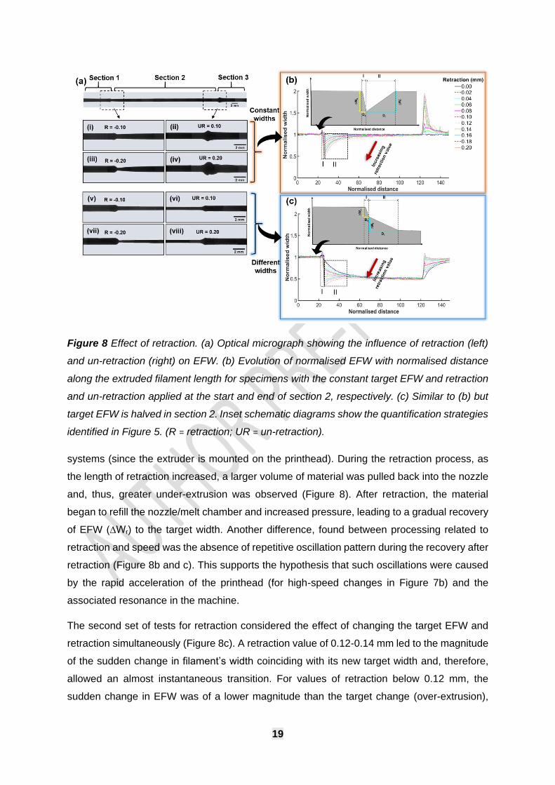
19
Figure 8 Effect of retraction. (a) Optical micrograph showing the influence of retraction (left)
and un-retraction (right) on EFW. (b) Evolution of normalised EFW with normalised distance
along the extruded filament length for specimens with the constant target EFW and retraction
and un-retraction applied at the start and end of section 2, respectively. (c) Similar to (b) but
target EFW is halved in section 2. Inset schematic diagrams show the quantification strategies
identified in Figure 5. (R = retraction; UR = un-retraction).
systems (since the extruder is mounted on the printhead). During the retraction process, as
the length of retraction increased, a larger volume of material was pulled back into the nozzle
and, thus, greater under-extrusion was observed (Figure 8). After retraction, the material
began to refill the nozzle/melt chamber and increased pressure, leading to a gradual recovery
of EFW (∆Wr) to the target width. Another difference, found between processing related to
retraction and speed was the absence of repetitive oscillation pattern during the recovery after
retraction (Figure 8b and c). This supports the hypothesis that such oscillations were caused
by the rapid acceleration of the printhead (for high-speed changes in Figure 7b) and the
associated resonance in the machine.
The second set of tests for retraction considered the effect of changing the target EFW and
retraction simultaneously (Figure 8c). A retraction value of 0.12-0.14 mm led to the magnitude
of the sudden change in filament’s width coinciding with its new target width and, therefore,
allowed an almost instantaneous transition. For values of retraction below 0.12 mm, the
sudden change in EFW was of a lower magnitude than the target change (over-extrusion),

20
and vice versa for retraction over 0.14 mm (under-extrusion). This led to a gradual recovery
to the target width after the initial sudden change in both cases.
The obtained data from Figure 7 and 8 were quantitatively characterised to analyse the effect
of speed and retraction on EFW in terms of the sudden change (∆Ws) and recovery (∆Wr)
(Figure 9). Retraction allowed up to 60% reduction in EFW to be completed over a relatively
constant and short distance (< 2x nozzle diameter), as shown in Figure 9a, whereas changing
speed required a slightly longer distance to achieve similar changes and the required distance
increased exponentially for changes in EFW over 40%.
The recovery data are plotted alongside the sudden-change data in Figure 9b, separated for
recovery after retraction and speed change. Recovery was a much slower process than the
sudden change, regardless of whether the recovery was instigated by change in speed or
retraction. Changing the speed resulted in a longer recovery, possibly due to a greater
imbalance between the required and actual pressure in the nozzle, whereas the retraction
recovery happened over a much shorter distance. This information is important from the
design point of view, as it can be used as a guidance map to support the choice of which print
parameters to vary in order to achieve the desired microscale geometry
Figure 9 (a) The normalised distance required to achieve different magnitudes of sudden
changes to EFW, due to speed-change and retraction. (b) Combined data for the normalised
distance versus the magnitude of EFW change for both sudden reductions and gradual
recovery to the target EFW. The printer (direct drive) was more responsive to retraction than
speed changes. The sudden initial changes to EFW were completed in approximately an order
of magnitude less distance than recovery to target EFW.

21
3.2 Comparison between direct drive and Bowden-tube printers
This section compares the response of the two types of printers in terms of the effect of
changes in speed and by retraction/un-retraction on EFW. These comparisons are then
repeated with different temperatures and accelerations, to understand the sensitivity and
transferability of the findings.
3.2.1 Print speed and retraction
A Bowden printer was studied in an equivalent manner to that of the direct drive printer
(Section 3.1). Initially, specimens with a constant target EFW along their length were studied.
The responses of EFW to the changing speed and retraction/un-retraction are shown in Figure
10a and b, respectively. For simplicity, three levels of low, medium and high speeds and
retraction values (see Supplementary Data) were selected to compare the results for the direct
drive (solid line) and Bowden (dashed line) printers. Additionally, the results for sets of
specimens with a 50% lower target EFW in section 2 versus sections 1 and 3 are shown in
Figure 10c and d.
As with the direct drive printer, the Bowden printer demonstrated a reduction in EFW when
speed increased, even for the constant target EFW (Figure 10a). This reduction was clearly
linked to the magnitude of speed change. However, in stark contrast to the direct drive, the
Bowden printer did not demonstrate any significant recovery and continued to under-extrude,
with measured EFW below target EFW (1.0), over the entire length of section 2 of the
specimens, regardless of speed. This can be explained by the large distance between the
feeder mechanism and the nozzle (compared to direct drive printers), resulting in a lag
between changes in achieved and target EFWs. The lag may be caused by a system’s slack
and slight deformation of the feedstock filament in the Bowden tube, since the compressive
forces are transmitted from the feeder along the entire length of the feedstock filament in the
tube. A similar conclusion can be obtained by comparing the results for the Bowden printer for
specimens with constant EFW and with 50% target EFW in section 2 (Figure 10a and c).
Whereas, the direct drive printer demonstrated a large difference between these specimen
types, the Bowden printer did not, highlighting the unresponsiveness of the latter to the
changes in target EFW (as discussed in relation to Figure 6).
The Bowden printer was also unresponsive to retraction (Figure 10b and d). Unlike the direct
drive printer, which responded to it with a logical short-term period of under-extrusion, the
Bowden printer showed the delayed and gradually increasing under-extrusion. The amount of
retraction did affect EFW, but even at high values of retraction (beyond those typically used
or recommended), EFW did not change responsively. In all cases, the Bowden printer
specimens did not recover to the target EFW during the entire length of section 2 (i.e. 100-fold

22
distance of nozzle diameter), as can be seen in Figure 10b. Similarly, when the target EFW
was changed in section 2 (Figure 10d), the Bowden printer did not demonstrate a significant
response to retraction.
Overall, it can be concluded that, for Bowden printers, EFW can be responsively influenced
by changing print speed, but not by changing the target EFW or retraction, whereas the direct
drive printer was responsive to all three parameters. However, the reduced weight of the
printhead for the Bowden printer resulted in a beneficial reduction in EFW oscillation (also
called ringing).
Figure 10 Comparison between direct drive (solid line) and Bowden tube (dashed line) printers
in terms of changing speed (a and c) and changing retraction settings (b and d). In the top row
(a and b), target EFW was constant throughout the whole specimen. For the bottom row (c
and d), EFW was reduced by 50% in section 2 compared to sections 1 and 3 of the specimens.
For both parameters, the direct drive printer was more responsive than the Bowden printer.
3.2.2 Effect of nozzle temperature
To test the resiliance of the above results to changes in nozzle temperature, the test specimen
with different target EFW in section 2 (defined in Section 2.2) was printed at 195°C, 205°C
and 215°C. The effects of print speed changes and retraction were considered.
Representative EFW profiles were selected to achieve low, medium and high groupings for
speed (Figure 11a and c) and retraction (Figure 11b and d) (see Supplementary Data for print
parameters). The results show that the trends found in this study were also observed for a

23
range of extrusion temperatures, giving confidence in the applicability and resilience of the
CONVEX design approach for both direct drive and Bowden printers.
Figure 11 Effect of different temperatures on filament geometry for direct drive and bowden
tube printers. (a and c) Effect of three levels of speed. (b and d) Effect of three levels of
retraction. Similar variations of EFW can be achieved at all three temperatures.
3.2.3 Effect of acceleration
The previous sections demonstrated the important effect that speed has on the extruded-
filament geometry. Since acceleration directly affects speed, a range of accelerations were
studied for 1.0-3.0-1.0 specimens. For both the direct drive and Bowden printers, it was
possible to achieve a gradual reduction in EFW at lower accelerations and a sudden reduction
at higher accelerations (Figure 12). The Bowden printer (Figure 12b) demonstrated a
controllable gradual change in EFW at both the beginning (reducing EFW) and the end
(increasing EFW) of section 2. The direct drive printer (Figure 12a) demonstrated a more
complicated trend, potentially resulting from attempts by the system firmware to compensate
for over-extrusion. The effect of jerk was also investigated but was found to have no significant
effect on EFW profiles, so the results are not shown here. The results for acceleration confirm
that it is an important parameter that can be used to control the transition between different
EFWs. This is demonstrated in a case study in Section 3.4.

24
Figure 12 Changing the acceleration allowed EFW to be varied with different degrees of
rapidity (from gradual to sudden) for both the direct drive (a) and Bowden (b) printers. Inset
optical images (i and ii) show a gradual reduction in width for acceleration 0.05 m.s-2, while
(iii) demonstrates a sudden reduction for acceleration 4.0 m.s-2.
3.3 Alternative materials and layer height
The transferability of results obtained in Sections 3.1 and 3.2 was investigated in terms of
material choice: PLA, ABS and nylon. By changing speed in section 2 of the specimen, it was
possible to achieve similar reductions in EFW for all three materials (Figure 13a). Furthermore,
this was possible for a range of EFW reductions for all materials (from 30% to 70% reduction)
as can be seen by the groupings into low, medium and high speeds in section 2 of the
specimens (print parameters given in Supplementary data). Based on these results, it is
expected that the findings of this study are applicable to a wide range of materials. In addition
to investigate the applicability of results to other layer heights, the effect of print speed at a
lower layer height (0.1 mm) was also investigated (Figure 13b). The obtained result was
compared against the reference layer height of 0.2 mm. The level of speed is still an effective
parameter for controlling EFW when layer height is reduced by 50% (see Supplementary Data
for print speed values).

25
Figure 13 (a) Normalised EFW could be controlled in a similar manner for three different
materials (PLA, ABS and nylon) by adjusting the speed in section 2 of specimens. Higher
speeds in section 2 led to a greater reduction in width. (b) Comparison between specimens
with 0.1 and 0.2 mm layer height and three levels of print speed showed the feasibility of
achieving width reduction in section 2 of the specimens with different layer heights.
A full comparison of the gradient of the sudden change upon changing different parameters
for both the direct drive and Bowden printers is presented in Figure 14. For major parameters,
including changing the speed and retraction, the direct drive printer (Figure 14a) appeared to
be more responsive because a wide range of magnitudes of EFW changes were achieved in
a normalised distance of approximately 1 to 3 (equivalent to 1-3x nozzle diameter) for most
parameters, whereas the Bowden printer achieved similar EFW changes in a normalised
distance of approximately 2 to 5. Also, retraction did not achieve controllable changes to EFW
for the Bowden printer (even for a normalised distance of 100), so does not feature in Figure
14b. For both printers, acceleration clearly enabled the normalised distance for changes to
EFW to be increased by up to ten-fold.
Furthermore, for specimens set to have a 50% reduction of EFW in section 2, the normalised
distance necessary to achieve this reduction was calculated for cases when (i) the extrusion
rate was changed only, and (ii) the extrusion rate was changed in combination with the speed
change or retraction. The responsiveness ratio, which is the ratio of normalised distance
required for case (i) divided by that for case (ii), was calculated to assess the responsiveness
Different
materials
Different
layer height
(b)
(a)

26
of the printers for different printing parameters: a ratio of 10 indicates a ten-fold reduction in
the distance required to achieve the new target EFW. The wide range in achievable ratios
(from 1 to >20), as shown in Figure 14c, demonstrates how broadly the geometry of the
filament can be controlled by the methods considered in this study. For the Bowden printer,
the target width was never achieved at a normalised distance of 100; thus, the responsiveness
ratio could not be measured but it was much greater than 20 (potentially higher than 100).
Figure 14 Comparison of the sudden change in EFW for different conditions printed by the
direct drive (a) and Bowden (b) printers. (c) The range of possible responsiveness ratios for
different printing conditions considered in this study. A: change speed only; B: change speed
+ target EFW; C: retraction only; D: retraction + target EFW; E/F: speed + target EFW at
195/215°C; G/H: retraction + target EFW at 195/215°C; I: speed + target EFW + acceleration;
J: different speed + target EFW + different materials.

27
3.4 Industrial applicability and case studies
Immediate industrial relevance: The method developed in this study to characterise the
dynamic response of extrusion process to changes in printer parameters has direct industrial
relevance for hardware development and validation. By repeating some aspects of this study
with different extruder/feeder hardware, it is possible to quantitatively compare performance
in terms of responsiveness, since many extruder/feeder mechanisms strive to optimise
responsiveness for aspects such as stopping/starting extrusion with retraction. Similar for the
development of new material formulations. The understanding can also be implemented in 3D
printing software to better optimise the print path and print parameters based on the printer
hardware (e.g. direct drive versus Bowden).
Other manufacturing processes: Although this study considers the MEAM process, the
CONVEX design concept can be translated to other manufacturing processes. For example,
in selective laser melting or sintering, the laser scanning speed could be controlled in a similar
way to nozzle travel speed in this study. By changing the scanning speed, the energy density
would immediately change, reducing the size of the melt pool. Similar opportunities exist for
other processes such as laser-based lithography, stereolithography, laser
cutting/etching/surface-treatment and material jetting. They can all achieve step-change
capability enhancements by using the CONVEX approach to design geometries below the
scale of nominal smallest feature (extruded filament / laser scan line / material jetting path).
Design potential: The findings presented in the above results sections highlight the potential
to design structures for MEAM using the CONVEX design approach to continuously and
controllably vary the geometry of individual filaments. In terms of design freedom, the results
in Figure 7d show the potential to design continuous extrusions with varying geometries across
a range at least from 75% to 250% of the nozzle diameter. Even the most advanced
capabilities within current “slicer” software packages and current research studies (e.g. setting
different values for EFW) do not consider design size scales similar to that used in this study
(e.g. designed and continuous variation of EFW). The newly demonstrated ability to control
the geometry of a single extruded filament while it is being printed (through combinations of
speed, acceleration, retraction and the set extrusion rate) opens up new possibilities for fields,
ranging from next generation slicers to completely new structures (e.g. new tissue engineering
scaffolds, drug delivery constructs, filters, mechanically graded infill lattices and microfluidic
mixers). Step-change capabilities are possible with CONVEX for even the most recent state-
of-the-art printing developments – for example free-standing pillar arrays [16] could be given
explicitly designed and continuously varying diameters. Furthermore, the results
demonstrating applicability of the findings to different extrusion temperatures, materials (PLA,
ABS, nylon) and layer heights, indicate the robustness and transferability of the method.

28
Application and case studies: Due to the complexity of the design of intricate structures, the
CONVEX design approach is most applicable to research fields and high-value applications,
where MEAM is being used to develop new metamaterials and microstructural geometries or
to manufacture final products/specimens. However, integration of the new understanding into
slicers may allow a more widespread use for larger-scale manufacturing. The first case study
below demonstrates the use of the CONVEX design approach in slicing algorithms to eliminate
pore defects. The second case study shows how CONVEX may enable the design of
structures at sub-filament size scales (i.e. with features smaller than the width of extruded
filaments) and the third case study demonstrated the potential for entirely new structure-
material designs.
3.4.1 Case study 1: “Streamline Slicing” application of CONVEX
In this case study, a rectangular tab with a tapered central section (shown schematically in
Figure 15a) was printed using two approaches: (i) conventional slicing software; (ii) the
CONVEX design approach with a streamlined print path (produced using in-house software
for GCODE generation).
For the version produced by slicing software, the printing direction in the slicer was set to be
in the Y direction, (dashed arrow in Figure 15a), which is the logical direction to achieve a neat
manufactured part. For the CONVEX version, the understanding developed in this study was
used to continuously vary EFW to match the overall design geometry. To achieve this gradual
narrowing of the extruded filaments, the magnitudes of speed and acceleration were
deliberately controlled (as highlighted in Figure 15b), based on the results related to
acceleration and EFW in Figure 12b.
For the part produced with the conventional slicing software, the perimeter of the design (i.e.
solid shell) was printed first, and then the remaining internal space was filled by an array of
filaments. Since the print speed and EFW were set by the slicing software at constant values
for each extruded filament, once the nozzle reached the transition point (i.e. reduction in width
meant fewer filaments were required to fill the space), it stopped and moved to the next line.
This resulted in multiple voids (Figure 15b, d and f) with the size in the range of 400 µm, similar
to those found in the literature which cause stress concentration and premature failure [31],
[32]. In contrast, since the CONVEX design utilised a constant number of extruded filaments
following the streamlined paths along the entire length of the part, there were no voids or
defects (Figure 15c and e).
This case study demonstrated a specific implementation of the CONVEX design approach,
based around the idea of “Streamline Slicing”, where the understanding developed in this
study allows EFW to be varied along a streamlined print path. It is particularly relevant for

29
parts with simple but non-uniform geometry that have stringent requirements for mechanical
integrity, effective sealing (no pore defects) for fluid application or pneumatics, or aesthetics.
Practically, this could be implemented in slicing software by allowing the user to specify the
streamline orientation or by selecting two faces of the CAD model to prescribe the start and
end of the streamlines.
Figure 15 (a) Schematic diagram indicating the print-platform orientation of a demonstration
part with a tapered central section that was manufactured using the conventional slicing
software and the custom G-Code (CONVEX design approach). The part is similar to the
dogbone geometry shown in Figure 2. Multiple pore defects approximately 400 µm long were
identified for specimens printed with the conventional slicing software (b, d and f) whereas the
CONVEX approach eliminated defects (c and e).

30
3.4.2 Case study 2: microscale geometric design application of CONVEX
For the second case study, a micro-tensile testing specimen was used in order to demonstrate
the potential to design structures with design features smaller than the extruded filament.
Currently, there is no standard for MEAM structure for tensile testing, and many research
groups use ASTM standards such as D638. However, a critical issue with this design is the
presence of void or seams between the extruded filaments, similar to those in the previous
case study (Figure 15). To overcome these issues, a filament-scale dogbone specimen
(Figure 16a) was printed, using the understanding from the results in Section 3.1 (Figure 7d)
to print the wide (grips) and narrow (gauge) sections in a single pass (Figure 16a and b). The
print speed for the gauge section of specimen was increased from 1.0 to 3.0 m.min-1 to quickly
adjust the filament width from the grips-section width to the gauge width.
For comparison, a CAD model of the design was used to print the same geometry with the
conventional slicing software. The part produced by conventional slicing software (Figure 16d)
contained void defects between the filaments similar to those described in the literature [20],
[31], [37], whereas the part manufactured using the CONVEX design approach demonstrated
neat and continuous extrusion (Figure 16c). This micro-tensile testing specimen, based on the
CONVEX design approach, enabled several research studies by the authors to develop new
fundamental understanding of mechanical performance in MEAM [15], [30], [33]. These would
not have been possible with conventional testing specimens and print-path approaches, and
the method is currently being translated to other fields.
There is a huge range of structures currently designed based on the unnecessarily assumed
limitation that filaments need a constant cross-section (e.g. tissue engineering scaffolds,
filters, fluid mixers, drug delivery constructs, infill patterns and mechanical lattices). By
reconsidering the geometric design of such structures based on the CONVEX design
approach, a step change in MEAM capability and understanding is possible.

31
Figure 16 (a) Schematic diagram of microscale dogbone tensile-testing specimen on print
platform. (b) Top-view schematic of dogbone specimen. (c) Micrograph of the part produced
with custom G-Code based on the CONVEX design approach demonstrating neat continuous
extrusion without defects. (d) Micrograph of the part produced with the conventional slicing
software with defects (pores shown by arrow) and inter-filament seams.
3.4.3 Case study 3: microscale geometrically graded mesh materials
A final case study demonstrates MEAM mesh materials with graded pore sizes that are
inconceivable and impossible to produce without CONVEX (Figure 17). Grading is normally
only possible through varying the geometry and position of an entire filament; CONVEX allows
entire new spatial freedom for design of mesh materials. In the case study, for different
specimens, print speed was set constant at 1.0 m.min-1 (Figure 17b) or varied from 0.5 to 2.0
m.min-1 according to linear and sinusoidal functions (Figure 17c-f). EFW was set to be constant
(0.5 mm) for the traditional mesh and varied up to 2-fold for the graded mesh materials. A
video of the printing process for these specimens is included as supplementary data. Since
the CONVEX design approach allows geometric grading without changing the print path, it is
possible to instantly vary grading for each layer whilst still ensuring effective contact with

32
filaments on lower layers. Conversely, for constrained print paths (e.g. conforming to
anatomical geometry) CONVEX offers new opportunities to control pore geometry. Since this
case study used a 50% larger nozzle than the rest of the study, it also highlights the potential
of CONVEX for alternative size-scales (e.g. small needles for biomedical applications or large
nozzles for construction and other large-scale MEAM).
Figure 17 (a) Photo of a mesh material specimen. Five designs were printed with and without
the CONVEX design approach: (b) traditional mesh design with constant EFW; (c) linearly
graded continuous variation of EFW; (d) sinusoidally graded EFW; (e) one-third-period
sinusoidally graded EFW; (f) similar to (e) with 67% wider EFW. Arrows indicate the grading
direction for pore-size reduction. For an identical print path, the CONVEX approach enabled
previously unconceivable mesh materials to be printed by continuously varying speed. Videos
of the variable-speed printing process are included in supplementary data.
4 Conclusions
The effect of print speed, retraction and acceleration on the geometry of single extruded
filaments was studied for two main classes of MEAM 3D printers (direct drive and Bowden).
The results demonstrated that by changing these parameters in a designed way, the geometry
(b) (f)(e)(d)(c)
Small
pores
Large
pores
(a)
2 mm
All use identical print path
(only EFW varied via CONVEX approach)

33
of the extruded filament could be controlled and varied along its length. The obtained results
indicated that direct drive printers were more responsive. In particular, retraction had a little
effect on the Bowden printer. Furthermore, for both printer types, it was possible to achieve
similar changes to extruded-filament geometry for a range of materials (PLA, ABS and nylon),
at temperatures 10°C above and below the recommended printing temperature, and for
different layer heights and nozzle sizes. Acceleration was used to directly affect the rate of
transitions between wider and narrower extruded-filament geometries. Three case studies
demonstrated the use of the newly developed understanding in the CONVEX design
approach, in which the width of extruded filaments is explicitly designed to achieve structures
that are not possible using a conventional slicer. The new approach opens up a new size scale
for design (e.g. tens of microns design resolution for a 0.4 mm nozzle) and the opportunity for
a step change in novel structural geometries as well as new potential for future 3D printing
slicer software.
5 Acknowledgement
This research did not receive any specific grant from funding agencies in the public,
commercial, or not-for-profit sectors.
Data Availability
The raw data (micrographs) required to reproduce these findings are available to download
from [TBC]. The processed data required to reproduce these findings (EFW profiles) are
available to download from [TBC].
Reference
[1] J. W. Stansbury and M. J. Idacavage, “3D printing with polymers: Challenges among
expanding options and opportunities,” Dent. Mater., vol. 32, no. 1, pp. 54–64, 2016.
[2] L. Safai, J. S. Cuellar, G. Smit, and A. A. Zadpoor, “A review of the fatigue behavior of
3D printed polymers,” Addit. Manuf., vol. 28, pp. 87–97, 2019.
[3] S. C. Ligon, R. Liska, J. Stampfl, M. Gurr, and R. Mülhaupt, “Polymers for 3D printing
and customized additive manufacturing,” Chem. Rev., vol. 117, no. 15, pp. 10212–
10290, 2017.
[4] L. G. Bracaglia, B. T. Smith, E. Watson, N. Arumugasaamy, A. G. Mikos, and J. P.
Fisher, “3D printing for the design and fabrication of polymer-based gradient
scaffolds,” Acta Biomater., vol. 56, pp. 3–13, Jul. 2017.

34
[5] S. Bose, S. Vahabzadeh, and A. Bandyopadhyay, “Bone tissue engineering using 3D
printing,” Mater. Today, vol. 16, no. 12, pp. 496–504, 2013.
[6] Z. Zhao, J. Bai, Y. Yao, and C. Wang, “Printing continuous metal structures via
polymer-assisted photochemical deposition,” Mater. Today, 2020.
[7] H. Zhao, X. Liu, W. Zhao, G. Wang, and B. Liu, “An Overview of Research on FDM
3D Printing Process of Continuous Fiber Reinforced Composites,” J. Phys. Conf. Ser.,
vol. 1213, p. 052037, 2019.
[8] U. K. uz Zaman, E. Boesch, A. Siadat, M. Rivette, and A. A. Baqai, “Impact of fused
deposition modeling (FDM) process parameters on strength of built parts using
Taguchi’s design of experiments,” Int. J. Adv. Manuf. Technol., vol. 101, pp. 1215–
1226, 2019.
[9] W. Zhu et al., “Rapid continuous 3D printing of customizable peripheral nerve
guidance conduits,” Mater. Today, vol. 21, no. 9, pp. 951–959, 2018.
[10] S. Petersmann et al., “Mechanical properties of polymeric implant materials produced
by extrusion-based additive manufacturing,” J. Mech. Behav. Biomed. Mater., vol.
104, p. 103611, 2020.
[11] P. Geng et al., “Effects of extrusion speed and printing speed on the 3D printing
stability of extruded PEEK filament,” J. Manuf. Process., vol. 37, no. 2019, pp. 266–
273, 2019.
[12] T. J. Coogan and D. O. Kazmer, “Healing simulation for bond strength prediction of
FDM,” Rapid Prototyp. J., vol. 23, no. 3, pp. 551–561, 2017.
[13] C. Pascual-gonzález, M. Iragi, A. Fernández, J. P. Fernández-blázquez, and L.
Aretxabaleta, “An approach to analyse the factors behind the micromechanical
response of 3D-printed composites,” Compos. Part B, vol. 186, p. 107820, 2020.
[14] Y. Zhang, C. Purssell, K. Mao, and S. Leigh, “A physical investigation of wear and
thermal characteristics of 3D printed nylon spur gears,” Tribol. Int., vol. 141, p.
105953, 2020.
[15] A. Gleadall, W. Poon, J. Allum, A. Ekinci, X. Han, and V. V. Silberschmidt, “Interfacial
fracture of 3D-printed bioresorbable polymers,” Procedia Struct. Integr., vol. 13, pp.
625–630, 2018.
[16] B. Nan, F. J. Galindo-Rosales, and J. M. F. Ferreira, “3D printing vertically: Direct ink
writing free-standing pillar arrays,” Mater. Today, vol. 35, no. April, pp. 16–24, 2020.

35
[17] A. Gleadall, D. Visscher, J. Yang, D. Thomas, and J. Segal, “Review of additive
manufactured tissue engineering scaffolds: relationship between geometry and
performance,” Burn. Trauma, vol. 6, pp. 1–16, 2018.
[18] V. E. Kuznetsov, A. G. Tavitov, O. D. Urzhumtsev, M. V. Mikhalin, and A. I. Moiseev,
“Hardware factors influencing strength of parts obtained by fused filament fabrication,”
Polymers (Basel)., vol. 11, no. 11, p. 1870, 2019.
[19] A. Sood, R. Ohdar, and S. Mahapatra, “Parametric appraisal of mechanical property
of fused deposition modelling processed parts,” Mater. Des., vol. 31, no. 1, pp. 287–
295, 2010.
[20] B. Rankouhi, S. Javadpour, F. Delfanian, and T. Letcher, “Failure analysis and
mechanical characterization of 3D printed ABS with respect to layer thickness and
orientation,” J. Fail. Anal. Prev., vol. 16, no. 3, pp. 467–481, 2016.
[21] I. Durgun and R. Ertan, “Experimental investigation of FDM process for improvement
of mechanical properties and production cost,” Rapid Prototyp. J., vol. 20, no. 3, pp.
228–235, 2014.
[22] S. Ziemian, M. Okwara, and C. Ziemian, “Tensile and fatigue behavior of layered
acrylonitrile butadiene styrene,” Rapid Prototyp. J., vol. 21, no. 3, pp. 270–278, 2015.
[23] F. Tamburrino, S. Graziosi, and M. Bordegoni, “The influence of slicing parameters on
the multi-material adhesion mechanisms of FDM printed parts: an exploratory study,”
Virtual Phys. Prototyp., vol. 14, no. 4, pp. 316–332, 2019.
[24] E. Nyberg, A. O’Sullivan, and W. Grayson, “ScafSlicr: A MATLAB-based slicing
algorithm to enable 3D-printing of tissue engineering scaffolds with heterogeneous
porous microarchitecture,” PLoS One, vol. 14, no. 11, p. e0225007, 2019.
[25] A. Gleadall, I. Ashcroft, and J. Segal, “VOLCO: A predictive model for 3D printed
microarchitecture,” Addit. Manuf., vol. 21, no. April, pp. 605–618, 2018.
[26] J. M. Barrios and P. E. Romero, “Decision tree methods for predicting surface
roughness in fused deposition modeling parts,” Materials (Basel)., vol. 12, no. 16, p.
2574, 2019.
[27] J. Wang, H. Xie, Z. Weng, T. Senthil, and L. Wu, “A novel approach to improve
mechanical properties of parts fabricated by fused deposition modeling,” Mater. Des.,
vol. 105, pp. 152–159, 2016.
[28] C. Chadha, A. E. Patterson, J. Allison, and I. Jasiuk, “Repair of high-value plastic

36
components using fused deposition modeling,” in Proceedings of the 30th Annual
International Solid Freeform Fabrication Symposium, 2019.
[29] H. I. Medellin-Castillo and J. Zaragoza-Siqueiros, “Design and manufacturing
strategies for fused deposition modelling in additive manufacturing: A review,”
Chinese J. Mech. Eng. (English Ed., vol. 32, no. 1, pp. 1–16, 2019.
[30] J. Allum, A. Moetazedian, A. Gleadall, and V. V Silberschmidt, “Interlayer bonding has
bulk-material strength in extrusion additive manufacturing: new understanding of
anisotropy,” Addit. Manuf., vol. 34, p. 101297, 2020.
[31] J. Lluch-Cerezo, R. Benavente, M. D. Meseguer, and S. C. Gutiérrez, “Study of
samples geometry to analyze mechanical properties in Fused Deposition Modeling
process (FDM),” Procedia Manuf., vol. 41, pp. 890–897, 2019.
[32] J. R. C. Dizon, A. H. Espera, Q. Chen, and R. C. Advincula, “Mechanical
characterization of 3D-printed polymers,” Addit. Manuf., vol. 20, no. December, pp.
44–67, 2018.
[33] A. Moetazedian, A. Gleadall, X. Han, and V. V. Silberschmidt, “Effect of environment
on mechanical properties of 3D printed polylactide for biomedical applications,” J.
Mech. Behav. Biomed. Mater., vol. 102, p. 103510, 2020.
[34] P. Gharge, “Velocity painting: paint your 3D prints with style,” All3DP, 2020. [Online].
Available: https://all3dp.com/2/velocity-painting-how-to-paint-your-3d-prints-with-
style/. [Accessed: 03-Feb-2020].
[35] A. Derossi, M. Paolillo, R. Caporizzi, and C. Severini, “Extending the 3D food printing
tests at high speed. Material deposition and effect of non-printing movements on the
final quality of printed structures,” J. Food Eng., vol. 275, no. 2020, p. 109865, 2020.
[36] S. Abdollahi, A. Davis, J. H. Miller, and A. W. Feinberg, “Expert-guided optimization
for 3D printing of soft and liquid materials,” PLoS One, vol. 13, no. 4, pp. 1–19, 2018.
[37] S. H. Ahn, M. Montero, D. Odell, S. Roundy, and P. Wright, “Anisotropic material
properties of fused deposition modeling ABS,” Rapid Prototyp. J., vol. 8, no. 4, pp.
248–257, 2002.