converter configuration
DESCRIPTION
Presentation slides - Selection of converter configuration.TRANSCRIPT
Converter Configurations
Anith Krishnan
College of Engineering, Kidangoor
August 6, 2013
Anith Krishnan College of Engineering, Kidangoor
Converter Configurations
Learning Objectives
The students should be able to
I list the factors that affect the choice of pulse number.
I choose the best converter configuration for the given pulsenumber.
Anith Krishnan College of Engineering, Kidangoor
Converter Configurations
Choice of Converter Configuration
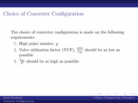
The choice of converter configuration is made on the followingrequirements:
1. High pulse number, p
2. Valve utilisation factor (VUF), PIVVd0
should be as low aspossible
3. Vd0E should be as high as possible
4. Transformer utilisation factor (TUF) should be as low aspossible (nearer to unity)
Anith Krishnan College of Engineering, Kidangoor
Converter Configurations
Choice of Converter Configuration
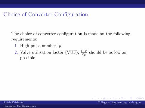
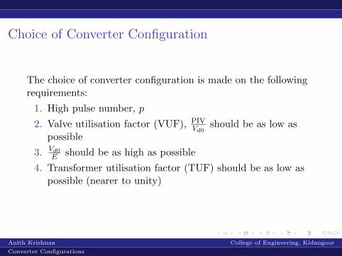
The choice of converter configuration is made on the followingrequirements:
1. High pulse number, p
2. Valve utilisation factor (VUF), PIVVd0
should be as low aspossible
3. Vd0E should be as high as possible
4. Transformer utilisation factor (TUF) should be as low aspossible (nearer to unity)
Anith Krishnan College of Engineering, Kidangoor
Converter Configurations
Pulse Number
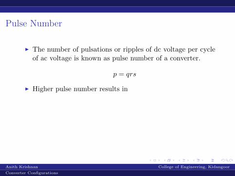
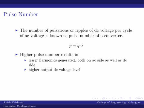
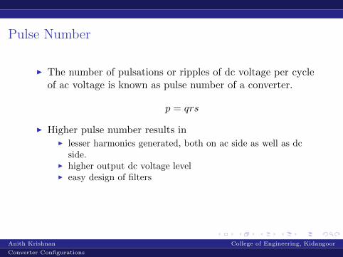
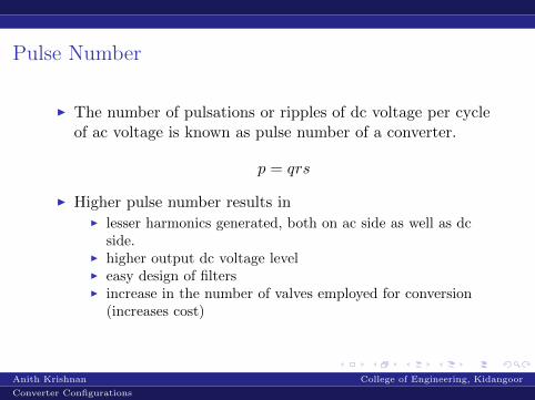
I The number of pulsations or ripples of dc voltage per cycleof ac voltage is known as pulse number of a converter.
p = qrs
I Higher pulse number results in
I lesser harmonics generated, both on ac side as well as dcside.
I higher output dc voltage levelI easy design of filtersI increase in the number of valves employed for conversion
(increases cost)
Anith Krishnan College of Engineering, Kidangoor
Converter Configurations

Pulse Number
I The number of pulsations or ripples of dc voltage per cycleof ac voltage is known as pulse number of a converter.
p = qrs
I Higher pulse number results inI lesser harmonics generated, both on ac side as well as dc
side.
I higher output dc voltage levelI easy design of filtersI increase in the number of valves employed for conversion
(increases cost)
Anith Krishnan College of Engineering, Kidangoor
Converter Configurations
Pulse Number
I The number of pulsations or ripples of dc voltage per cycleof ac voltage is known as pulse number of a converter.
p = qrs
I Higher pulse number results inI lesser harmonics generated, both on ac side as well as dc
side.I higher output dc voltage level
I easy design of filtersI increase in the number of valves employed for conversion
(increases cost)
Anith Krishnan College of Engineering, Kidangoor
Converter Configurations
Pulse Number
I The number of pulsations or ripples of dc voltage per cycleof ac voltage is known as pulse number of a converter.
p = qrs
I Higher pulse number results inI lesser harmonics generated, both on ac side as well as dc
side.I higher output dc voltage levelI easy design of filters
I increase in the number of valves employed for conversion(increases cost)
Anith Krishnan College of Engineering, Kidangoor
Converter Configurations
Pulse Number
I The number of pulsations or ripples of dc voltage per cycleof ac voltage is known as pulse number of a converter.
p = qrs
I Higher pulse number results inI lesser harmonics generated, both on ac side as well as dc
side.I higher output dc voltage levelI easy design of filtersI increase in the number of valves employed for conversion
(increases cost)
Anith Krishnan College of Engineering, Kidangoor
Converter Configurations
Valve Utilisation Factor
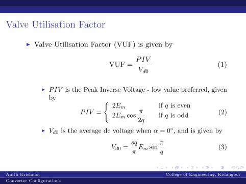
I Valve Utilisation Factor (VUF) is given by
VUF =PIV
Vd0(1)
I PIV is the Peak Inverse Voltage - low value preferred, givenby
PIV =
{2Em if q is even
2Em cosπ
2qif q is odd (2)
I Vd0 is the average dc voltage when α = 0◦, and is given by
Vd0 =sq
πEm sin
π
q(3)
Anith Krishnan College of Engineering, Kidangoor
Converter Configurations
Valve Utilisation Factor
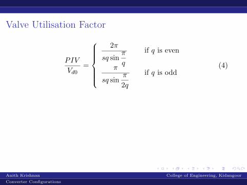
PIV
Vd0=
2π
sq sinπ
q
if q is even
π
sq sinπ
2q
if q is odd(4)
Anith Krishnan College of Engineering, Kidangoor
Converter Configurations
Vd0E
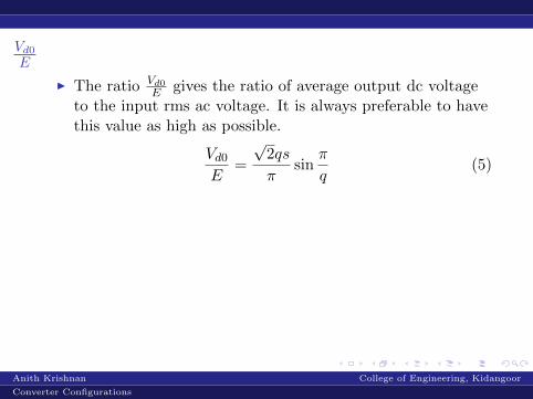
I The ratio Vd0E gives the ratio of average output dc voltage
to the input rms ac voltage. It is always preferable to havethis value as high as possible.
Vd0E
=
√2qs
πsin
π
q(5)
Anith Krishnan College of Engineering, Kidangoor
Converter Configurations

Transformer Utilisation FactorTUF is defined as the ratio of transformer rating (of the valveside) to the dc output power. A low value of TUF is preferred.
TUF =Pt
Vd0Id(6)
I The current rating of the transformer is given by
It =Idr√q
(7)
I The transformer rating is
Pt = pEm√
2It = p
EmIdr√
2q(8)
Thus
TUF =Pt
Vd0Id=
π√2q sin π
q
(9)
Anith Krishnan College of Engineering, Kidangoor
Converter Configurations
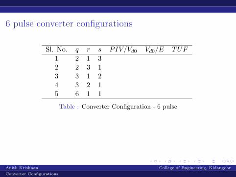
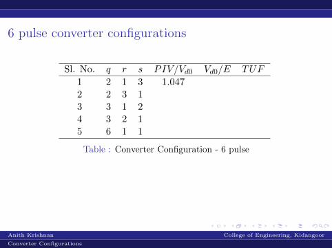
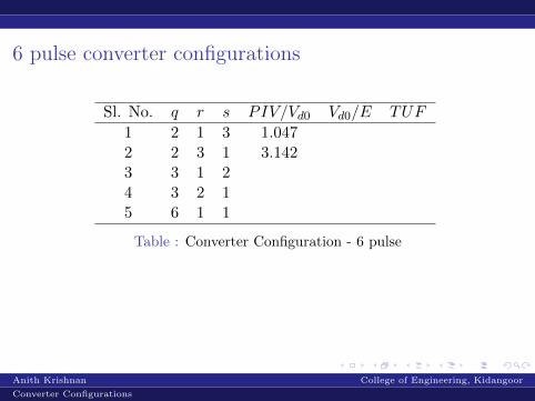
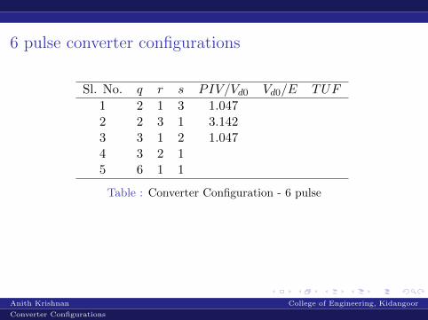
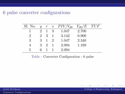
6 pulse converter configurations
Sl. No. q r s PIV/Vd0 Vd0/E TUF
1 2 1 3
1.047 2.700 1.571
2 2 3 1
3.142 0.900 1.571
3 3 1 2
1.047 2.340 1.481
4 3 2 1
2.094 1.169 1.481
5 6 1 1
2.094 1.350 1.814
Table : Converter Configuration - 6 pulse
From the table it can be seen that sl. no. 1 and 3 are suitable,but TUF is better for sl. no. 3. Since 3 phase supply is used,the ease of connection is an added advantage in using sl. no. 3.
Anith Krishnan College of Engineering, Kidangoor
Converter Configurations
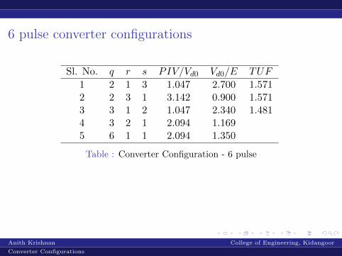
6 pulse converter configurations
Sl. No. q r s PIV/Vd0 Vd0/E TUF
1 2 1 3 1.047
2.700 1.571
2 2 3 1
3.142 0.900 1.571
3 3 1 2
1.047 2.340 1.481
4 3 2 1
2.094 1.169 1.481
5 6 1 1
2.094 1.350 1.814
Table : Converter Configuration - 6 pulse
From the table it can be seen that sl. no. 1 and 3 are suitable,but TUF is better for sl. no. 3. Since 3 phase supply is used,the ease of connection is an added advantage in using sl. no. 3.
Anith Krishnan College of Engineering, Kidangoor
Converter Configurations
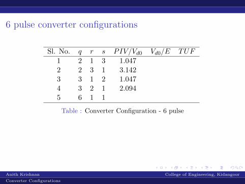
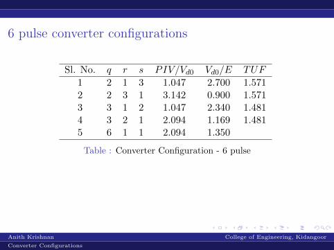
6 pulse converter configurations
Sl. No. q r s PIV/Vd0 Vd0/E TUF
1 2 1 3 1.047
2.700 1.571
2 2 3 1 3.142
0.900 1.571
3 3 1 2
1.047 2.340 1.481
4 3 2 1
2.094 1.169 1.481
5 6 1 1
2.094 1.350 1.814
Table : Converter Configuration - 6 pulse
From the table it can be seen that sl. no. 1 and 3 are suitable,but TUF is better for sl. no. 3. Since 3 phase supply is used,the ease of connection is an added advantage in using sl. no. 3.
Anith Krishnan College of Engineering, Kidangoor
Converter Configurations
6 pulse converter configurations
Sl. No. q r s PIV/Vd0 Vd0/E TUF
1 2 1 3 1.047
2.700 1.571
2 2 3 1 3.142
0.900 1.571
3 3 1 2 1.047
2.340 1.481
4 3 2 1 2.094
1.169 1.481
5 6 1 1
2.094 1.350 1.814
Table : Converter Configuration - 6 pulse
From the table it can be seen that sl. no. 1 and 3 are suitable,but TUF is better for sl. no. 3. Since 3 phase supply is used,the ease of connection is an added advantage in using sl. no. 3.
Anith Krishnan College of Engineering, Kidangoor
Converter Configurations

6 pulse converter configurations
Sl. No. q r s PIV/Vd0 Vd0/E TUF
1 2 1 3 1.047
2.700 1.571
2 2 3 1 3.142
0.900 1.571
3 3 1 2 1.047
2.340 1.481
4 3 2 1 2.094
1.169 1.481
5 6 1 1 2.094
1.350 1.814
Table : Converter Configuration - 6 pulse
From the table it can be seen that sl. no. 1 and 3 are suitable,but TUF is better for sl. no. 3. Since 3 phase supply is used,the ease of connection is an added advantage in using sl. no. 3.
Anith Krishnan College of Engineering, Kidangoor
Converter Configurations

6 pulse converter configurations
Sl. No. q r s PIV/Vd0 Vd0/E TUF
1 2 1 3 1.047 2.700
1.571
2 2 3 1 3.142
0.900 1.571
3 3 1 2 1.047
2.340 1.481
4 3 2 1 2.094
1.169 1.481
5 6 1 1 2.094
1.350 1.814
Table : Converter Configuration - 6 pulse
From the table it can be seen that sl. no. 1 and 3 are suitable,but TUF is better for sl. no. 3. Since 3 phase supply is used,the ease of connection is an added advantage in using sl. no. 3.
Anith Krishnan College of Engineering, Kidangoor
Converter Configurations
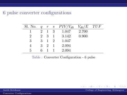
6 pulse converter configurations
Sl. No. q r s PIV/Vd0 Vd0/E TUF
1 2 1 3 1.047 2.700
1.571
2 2 3 1 3.142 0.900
1.571
3 3 1 2 1.047
2.340 1.481
4 3 2 1 2.094
1.169 1.481
5 6 1 1 2.094
1.350 1.814
Table : Converter Configuration - 6 pulse
From the table it can be seen that sl. no. 1 and 3 are suitable,but TUF is better for sl. no. 3. Since 3 phase supply is used,the ease of connection is an added advantage in using sl. no. 3.
Anith Krishnan College of Engineering, Kidangoor
Converter Configurations
6 pulse converter configurations
Sl. No. q r s PIV/Vd0 Vd0/E TUF
1 2 1 3 1.047 2.700
1.571
2 2 3 1 3.142 0.900
1.571
3 3 1 2 1.047 2.340
1.481
4 3 2 1 2.094
1.169 1.481
5 6 1 1 2.094
1.350 1.814
Table : Converter Configuration - 6 pulse
From the table it can be seen that sl. no. 1 and 3 are suitable,but TUF is better for sl. no. 3. Since 3 phase supply is used,the ease of connection is an added advantage in using sl. no. 3.
Anith Krishnan College of Engineering, Kidangoor
Converter Configurations
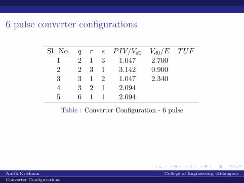
6 pulse converter configurations
Sl. No. q r s PIV/Vd0 Vd0/E TUF
1 2 1 3 1.047 2.700
1.571
2 2 3 1 3.142 0.900
1.571
3 3 1 2 1.047 2.340
1.481
4 3 2 1 2.094 1.169
1.481
5 6 1 1 2.094 1.350
1.814
Table : Converter Configuration - 6 pulse
From the table it can be seen that sl. no. 1 and 3 are suitable,but TUF is better for sl. no. 3. Since 3 phase supply is used,the ease of connection is an added advantage in using sl. no. 3.
Anith Krishnan College of Engineering, Kidangoor
Converter Configurations

6 pulse converter configurations
Sl. No. q r s PIV/Vd0 Vd0/E TUF
1 2 1 3 1.047 2.700 1.5712 2 3 1 3.142 0.900
1.571
3 3 1 2 1.047 2.340
1.481
4 3 2 1 2.094 1.169
1.481
5 6 1 1 2.094 1.350
1.814
Table : Converter Configuration - 6 pulse
From the table it can be seen that sl. no. 1 and 3 are suitable,but TUF is better for sl. no. 3. Since 3 phase supply is used,the ease of connection is an added advantage in using sl. no. 3.
Anith Krishnan College of Engineering, Kidangoor
Converter Configurations

6 pulse converter configurations
Sl. No. q r s PIV/Vd0 Vd0/E TUF
1 2 1 3 1.047 2.700 1.5712 2 3 1 3.142 0.900 1.5713 3 1 2 1.047 2.340
1.481
4 3 2 1 2.094 1.169
1.481
5 6 1 1 2.094 1.350
1.814
Table : Converter Configuration - 6 pulse
From the table it can be seen that sl. no. 1 and 3 are suitable,but TUF is better for sl. no. 3. Since 3 phase supply is used,the ease of connection is an added advantage in using sl. no. 3.
Anith Krishnan College of Engineering, Kidangoor
Converter Configurations
6 pulse converter configurations
Sl. No. q r s PIV/Vd0 Vd0/E TUF
1 2 1 3 1.047 2.700 1.5712 2 3 1 3.142 0.900 1.5713 3 1 2 1.047 2.340 1.4814 3 2 1 2.094 1.169
1.481
5 6 1 1 2.094 1.350
1.814
Table : Converter Configuration - 6 pulse
From the table it can be seen that sl. no. 1 and 3 are suitable,but TUF is better for sl. no. 3. Since 3 phase supply is used,the ease of connection is an added advantage in using sl. no. 3.
Anith Krishnan College of Engineering, Kidangoor
Converter Configurations
6 pulse converter configurations
Sl. No. q r s PIV/Vd0 Vd0/E TUF
1 2 1 3 1.047 2.700 1.5712 2 3 1 3.142 0.900 1.5713 3 1 2 1.047 2.340 1.4814 3 2 1 2.094 1.169 1.4815 6 1 1 2.094 1.350
1.814
Table : Converter Configuration - 6 pulse
From the table it can be seen that sl. no. 1 and 3 are suitable,but TUF is better for sl. no. 3. Since 3 phase supply is used,the ease of connection is an added advantage in using sl. no. 3.
Anith Krishnan College of Engineering, Kidangoor
Converter Configurations
6 pulse converter configurations
Sl. No. q r s PIV/Vd0 Vd0/E TUF
1 2 1 3 1.047 2.700 1.5712 2 3 1 3.142 0.900 1.5713 3 1 2 1.047 2.340 1.4814 3 2 1 2.094 1.169 1.4815 6 1 1 2.094 1.350 1.814
Table : Converter Configuration - 6 pulse
From the table it can be seen that sl. no. 1 and 3 are suitable,but TUF is better for sl. no. 3. Since 3 phase supply is used,the ease of connection is an added advantage in using sl. no. 3.
Anith Krishnan College of Engineering, Kidangoor
Converter Configurations
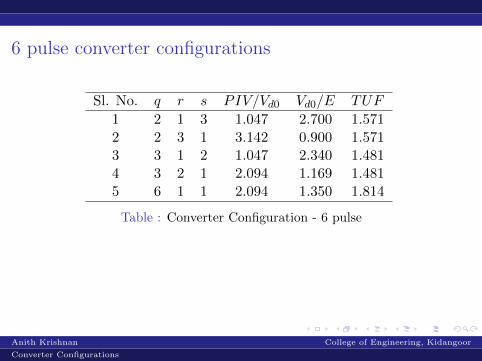
6 pulse converter configurations
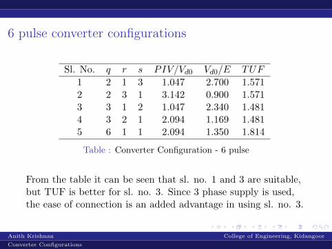
Sl. No. q r s PIV/Vd0 Vd0/E TUF
1 2 1 3 1.047 2.700 1.5712 2 3 1 3.142 0.900 1.5713 3 1 2 1.047 2.340 1.4814 3 2 1 2.094 1.169 1.4815 6 1 1 2.094 1.350 1.814
Table : Converter Configuration - 6 pulse
From the table it can be seen that sl. no. 1 and 3 are suitable,but TUF is better for sl. no. 3. Since 3 phase supply is used,the ease of connection is an added advantage in using sl. no. 3.
Anith Krishnan College of Engineering, Kidangoor
Converter Configurations
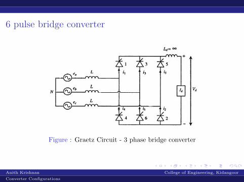
6 pulse bridge converter
Figure : Graetz Circuit - 3 phase bridge converter
Anith Krishnan College of Engineering, Kidangoor
Converter Configurations