conversion to vacuum switches in mercury cell chlorine plants
TRANSCRIPT

Conversion to Vacuum Switches in Mercury Cell Chlorine Plants
Watteredge, Inc. (Westinghouse Industrial and Government Tube Division at the time) began the studyand field trials of vacuum contact modules in the early 1970's with full plant installations (Chlor-alkalimercury cells) commencing in 1975. Since that time, upwards of 100,000 VCM's of various designs andapplications have been installed. Typical applications include:
1. Chlor-alkali cells - Membrane, Diaphragm, and Mercury Cell Process2. Electrolytic Manganese Dioxide3. Copper Refining4. Magnesium Production5. Rectifier Isolation
In all cases, the VCM has provided superior performance and life characteristics in comparison toair-contact and other switch technologies in the electrolytic process industry.
VCM Types
WX-32823 "Standard" VCM, Rated 6.25kA. Support Plates constructed of Epoxy-Coated Cold
Rolled Steel. This VCM has been the primary workhorse of Watteredge, Inc.
switches, normally used in all Chlor-alkali mercury cell "fixed" switches, and most
other non-metals refining applications. Proprietary alloy of contact material allows
for 6.25kA rating vs. 5.0kA rating for most other VCM designs.
WX-33300 Rated 6.25kA, uses same contact material as WX-32823, but is constructed of epoxy-
coated stainless steel support plates. Used in metals refining applications where
switch will be operated in a NO LOAD, i.e. power source turned off before opening,
installation. Normally ceramic and diaphragm region is urethane-potted to reduce
corrosive activity on metal component.
WX-34777 Rated 5.0kA, commonly referred to as a "High Energy" VCM. Contact material
utilizes a proprietary alloy to offer good electrical conductivity, but to also limit the
effects of high-energy arcing, normally experienced in ON LOAD opening in highly-
inductive copper-refining bus systems. Support plates constructed of epoxy-coated
stainless steel. Ceramic and diaphragm region urethane-potted to resist corrosive
metal-refining environment.

Conversion to Vacuum Switches in Mercury Cell Chlorine Plants
WX-34778 Rated 5.0kA, same as WX-34777 but support plates are epoxy-coated cold rolled
steel. Normally not potted. This VCM is solely for use in Watteredge, Inc. Matrix
Portable Jumper Switch elements. The switch element is water cooled, allowing this
VCM to carry between 7.0 and 12.5kA. The high energy contact material prolongs
the life of the VCM as it operates in Matrix Jumper Switch assemblies shorting and
opening on currents from 65kA to 170kA. The Watteredge, Inc. Matrix switch
designates anywhere from one to four of these VCM's to be in the "sacrificial"
position (one of the last contacts to open, taking the brunt of the electrical arc energy).
Normally these contacts are changed out once every 200-300 switch operations at full
load (about 1 year of operation in a typical Chlor-alkali plant). Investigation of the
contact faces after 300 + operations at full load has shown very acceptable performing
as designed and expected.
VCM Application/Selection Criteria
VCM P/NCurrentRating
Max.Resistance
TypicalApplication Features
WX-32823 6.25kA 2 micro-ohms Chlor-Alkali, Non-Metals Refining
Standard VCM
WX-33300 6.25kA 2 micro-ohms Metals-RefiningNo-Load Opening
SST ConstructionUrethane Potting
WX-34777 5.0kA 5 micro-ohms Metals-RefiningNo-Load Opening
High EnergyContact MaterialSST ConstructionUrethane Potting
WX-34778 5.0kA 5 micro-ohms Matrix SwitchElements
High EnergyContact Material
Vacuum Enclosed Contacts
Although some obvious advantages can be had by simply enclosing the switch contacts, the completesolution is a permanently sealed vacuum enclosure. Besides excluding completely hostile outsideinfluences, the superior dielectric of vacuum permits a cleaner, quicker current interruption and mostimportant of all, an end to the runaway feedback system of heat to oxidation to higher resistance to moreheat. Although not as easily evaluated, the safety feature of a totally enclosed contact system is certainlyworth consideration.

Conversion to Vacuum Switches in Mercury Cell Chlorine Plants
The heart of the vacuum switch is a vacuum enclosed contact moduleshown schematically in Fig. 1. A pair of heavy copper cylinders facedwith contact material form the current path. The vacuum enclosureconsists of a pair of corrugated diaphragms separated by an insulatingceramic sleeve. The seams are sealed by high temperature brazes.With this type of seal, the vacuum is permanent and will not graduallydeteriorate.
The flexibility to separate the contacts comes from the diaphragms.Because of the excellent dielectric properties of vacuum, the contactsneed only open a microscopic amount. However, for an added measureof safety, the contact separation is designed for 3mm or about 1/8 inch.
Switch Assembly
The external connection the vacuum module also offers an improvementover normal bus connection technique. The outside ends of the contactare dead soft copper. This surface is embedded in the mating flex or busplate surface by a clamping plate held by four highly stressed bolts. Theresulting joint, protected with a joint compound, is effectively a hermeticseal on its own and behaves as a permanent, low resistance connection –even in the fact of high bus temperatures.
A 90° rotation of the switch drive shaft produces the required contact motion through an eccentric camand link combination. In the closed position, the 100 or so pounds of atmospheric pressure bearing on thecontacts adds to the positive cam pressure applied through the link and belleville overtravel washers. Thebelleville washers have the unique property of a nearly constant force spring. This insures that the properforce will be applied to the contacts in spite of wear and drive misalignments. It also permitsinterchanging the vacuum modules without need of mechanism readjustment.
The basic vacuum module pole is rated at 6.25 kA continuously. Higher current ratings are achieved bygrouping two or more such modules in an assembly. Figures 2 to 5 are photographs of typical two, threeand four module assemblies.
Conversion to Vacuum Switches in Mercury Cell Chlorine Plants
Vacuum Contact Phenomena
As is often the case, a new development, besides producing its intended result, brings with it someworthwhile spin off. The singularly low contact resistance of vacuum contacts is a typical example.Because the contacts are totally free of any contamination, one expects a low resistance; the measuredresistance is even lower than expected. The improvement comes from a welding phenomenon in vacuum.
When two clean surfaces are brought together in a vacuum, they weld. If the surfaces are switch contactsclosing on a high current, the weld is quite extensive, thus accounting for the low contact resistance.This weld could present a difficulty during opening, in fact, the welding phenomenon is what delayed theintroduction of the vacuum switch. The solution was a high conductivity contact material which bothwelds and separates easily. The result is a significantly lower millivolt drop across the switch, less powerlost, lower operating temperature, and ultimately, longer life.
In addition to the lower millivolt drop, this property brings two other significant improvements to theuser:
First, the runaway condition mentioned earlier is absent in the vacuum switch. Added load on thevacuum switch will simply cause it to run hotter and, subject to the limitations of the external parts – flexand bus bar – there appears to be no limit to the switches current carrying capacity, short of melting it –over 800ºC. This means the vacuum switch will survive the inevitable temporary overloads encounteredin mercury cell room service.
The second is the constancy of the contact resistance over the life of the switch life. Attention to themillivolt drop of the shorted switches can, therefore, be used as a diagnostic for bad bus joints, improperanode setting, or a defective switch. If, for instance, the vacuum enclosure of a switch is accidentallypunctured, that switch will behave as a typical exposed contact switch with perhaps double the normalvoltage drop. The problem can be corrected or the switch changed when convenient – note that vacuumfailure in a switch is not an emergency condition, the switch will still continue to function.
Transient Performance
The layout of a mercury cell room requires that the cell switch be divided into a number of individualswitches according to the anode bus grouping. Furthermore, each individual switch is usually sub-divided into multiple contact sets. While this fractionalization facilitates cell design and switch design, ithas introduced a major cause of switch deterioration-asynchronism. It is an inescapable fact that acrossthe cell, one contact will close first and one-not necessarily the same one-will open last. The affectedswitches are subject to highly destructive contact erosion. The degree of asynchronism or more precisely,the time delays between contacts opening or closing, has a direct bearing on the about of erosion.Vacuum contacts have been particularly successful in coping with this. Contacts that would requireredressing after only a few operations in air, last thousands of operations in vacuum.
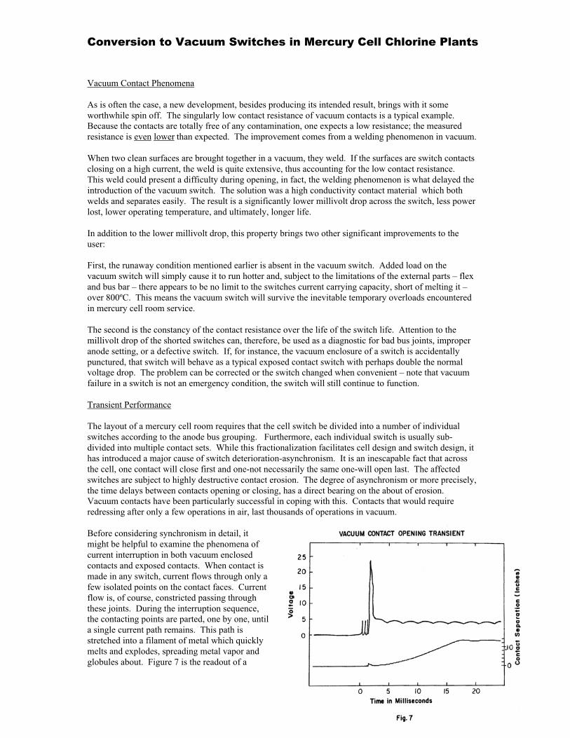
Before considering synchronism in detail, itmight be helpful to examine the phenomena ofcurrent interruption in both vacuum enclosedcontacts and exposed contacts. When contact ismade in any switch, current flows through only afew isolated points on the contact faces. Currentflow is, of course, constricted passing throughthese joints. During the interruption sequence,the contacting points are parted, one by one, untila single current path remains. This path isstretched into a filament of metal which quicklymelts and explodes, spreading metal vapor andglobules about. Figure 7 is the readout of a

Conversion to Vacuum Switches in Mercury Cell Chlorine Plants
digital oscilloscope recording of an opening event. The voltage drop is the upper curve and the contactposition is the lower. The short, irregular segment of the voltage curve just preceding the interruption isevidence of this filament in the process of melting and dispersing. Note how little the contacts havemoved before the current is interrupted. This is the shower of sparks seen during the functioning of anexposed contact switch. Besides losing material, the exposed contacts suffer oxidation and deposition ofoxidized metal. The vacuum enclosed contacts, however, are immune from the oxidation problem.Emitted material remains in the form of clean metal so that when it is deposited on adjacent contact area,it forms a reusable contact surface rather than a high resistance film. As a consequence of the smallerseparation of the vacuum contacts, the emission of material is restricted, allowing a higher percentage tobe returned to active use on the contact face. Vacuum contacts sampled after a number of high currentinterruptions show an irregular pattern of pits and protrusions with a matching pattern on the oppositecontact face. Instead of reducing the effectiveness of the contact, the irregularity of the vacuum contactsactually seems to improve it after the first few operations. This is due to an increased number of contactpoints available on the roughened surface vs. the fresh surface. Five thousand operations at rated load inthe test produced insignificant wear, perhaps 50 years of life in a chlorine plant.
Obviously, the more current a contact is asked to interrupt, the more erosion will take place. At firstglance one might assume that the first switch to close and the last switch to open must take the entireplant load. Fortunately, this is not the case during a typical cell switch operation. There are, of course,transient unbalances in switch loading during the opening or closing sequence.
As you can imagine, little data on thisphenomenon exists and measurements on site arequite difficult. However, a computer simulation ofa cell room was made, the results of which arepresented in Figures 8 and 9. The curves shown inFigure 8 represent the current distribution in thecell after the first switch is closed but before anyother switches close. This current would rise toapproximately double the normal plant load if noother switch closed. Of course, as other contactsclose, the load is shared. The extra current comesfrom the battery effect of the cell adding to thenormal load. Although the battery dischargecurrent tapers off quickly, it persists long enoughto be a consideration during switch closing. Themaximum current a switch can carry during atransient of this type depends on its ability to withstand the magnetic forces trying to pop it open. Asingle contact in a vacuum switch assembly can close on well in excess of 50 kA. This allowsconsiderable margin of safety with typical drive systems – even if the shaft must be hand-operated inemergency.
The opening sequence is pictured in Figure 9.The assumption here is that all 8 switches areconnected in tandem, each with a nominalbacklash, and the openings proceed from one endto the other. This could also represent half of a 16switch cell driven from the center. Note that aseach switch opens, it loads its neighbors until thelast switch is carrying approximately 2 _ timesnormal current when it opens. With shorterdelays between switch closings, the overload onthe last switch is reduced – in fact, if all contactsopen simultaneously, there will be no problem.Of course, this is not possible and even a well-synchronized switch set will deteriorate.

Conversion to Vacuum Switches in Mercury Cell Chlorine Plants
The vacuum switch handles the problem in a unique manner. The last set of contacts to mechanicallyseparate is not necessarily the last contacts to carry current. In a vacuum, the filamentary bridge of metalformed during interruption frequently reforms several times within the first few milliseconds. SeeFigure 7. This is a random phenomenon which has the effect of reducing the current buildup in the lastcontacts to physically open. This effect, together with the already good interruption capability, is thereason for the vacuum switches superior performance in chorine cell switching.
Drive Requirement
Although our primary concern is with vacuum switches, we are often asked to recommend or supply thedrive system. Since the transient problems previously discussed are largely the result of a less than idealdrive, some judgement must be used in matching switches to the drive system – particularly in retrofits.
The criteria for a good drive are speed andsynchronism, that is, all switches in a cellshould actuate as quickly and as nearly togetheras possible. Some systems do this much betterthan others. One of the best systems in the airactuated jackshaft to which each switch iscoupled individually or in pairs as in Figures 10A and B: one of the worst is a system ofindividual air cylinders on each switch. It takeslittle imagination to visualize the results of asingle balky air cylinder to the latter case. Mostsystems presently used lie somewhere inbetween as in Figures 11 and 12, and have thecommon advantage of solid mechanicalcoupling. In general, the more driven jointsbetween the drive and the last switch, the lessdesirable the system is from the standpoint ofswitch contact wear. The computer simulationassumes the drive system in Figure 12 where allswitches are in tandem, and, thus, must operate sequentially. The speed of the actuating mechanism is ofequal importance in evaluating a system. Any lack of synchronism in the switch couplings is magnifiedby a slower actuation.
These parameters are largely under the control of the user. Routine maintenance items such as goodlubrication of the drive and elimination of backlash from worn parts help prevent insidious contact erosioncaused by an unnoticed slowdown in the mechanism speed. Fluctuating air pressure or insufficient airdelivery can be corrected by an accumulator or larger air lines.
The switch manufacturer for his part must build in synchronism into his multiple contact assemblies. Littleis gained by careful alignment of the drive system if the individual contacts within a switch are badlystaggered. This internal synchronism has been a prime consideration in the choice of operating mechanismfor the vacuum switch. All contacts are designed to open with 1.25º of a specified shaft angle. Translatedinto a time frame, all contacts open with 2 to 4 milliseconds of each other when driven by a typical system.
Vacuum switch assemblies can, therefore, be adapted to almost any existing drive system. Its very lowtorque requirement (approximately 9 foot pounds per vacuum module) even helps speed up the systemwhen it replaces a high friction, open contact switch. We do not, however, recommend systems that are notmechanically coupled except in special applications where the total plant load is low – say, under 50 kA.

Conversion to Vacuum Switches in Mercury Cell Chlorine Plants
Figures 13, 14, 15, 16, illustrate how the vacuum switch is fitted into some common cell types.
Safety
It is general knowledge that the chlorine industry places a very high priority on personnel health andsafety.
The vacuum shorting switch makes a positive contribution to safety improvement by eliminating flyinghot metal and high intensity arcing.
Also, since there is zero maintenance required by vacuum contacts, the need for potentially toxic cleaningsolutions and abrasive materials is eliminated.

Conversion to Vacuum Switches in Mercury Cell Chlorine Plants
Conversion to Vacuum Switches in Mercury Cell Chlorine Plants

Conversion to Vacuum Switches in Mercury Cell Chlorine Plants

Conversion to Vacuum Switches in Mercury Cell Chlorine Plants

Conversion to Vacuum Switches in Mercury Cell Chlorine Plants