conventional energy sources and power system …eebag/power system components and...
TRANSCRIPT

Conventional Energy
Sources and Power
System Components
Y. Baghzouz
Professor of Electrical Engineering
University of Nevada, Las Vegas

Overview
Power Generation
Conventional type of different generation
Power transmission
Cables and other transmission system equipment
Power Distribution
Distribution system equipment
Power Utilization
Demand curves

Basic Conventional Power System Layout
Conventional (non-renewable)
primary energy source

World Electricity Generation
(Source: OECD/IEA 2010)

US Electricity Generation by Fuel

Energy production by country (past 3 yrs.)
(Source: OECD/IEA, 2012)
USA Italy
France Switzerland

Coal Fired Power Plants:
Number of Generators ≈ 1,450
Total Capacity ≈ 350 GW
(Source: http://www.npr.org)

Diagram of a modern coal power plant
(Source: Masters, Renewable and Efficient Electric Power Systems, 2004)

Steam Turbines and their Governors
Steam turbines can have non-reheat, single-reheat or double-reheat.
The steam flow is controlled by the governor. The main amplifier of the governing system and valve mover is an oil servomotor that is controlled by a pilot valve.
Main and reheat stop valves are normally fully open - they are used only during generator start-up and shut down.

The electric generator
Governor controls turbine torque and power
Exciter controls voltage and reactive power

Generator Exciter (brushless)

Generator Exciter
Generator Exciter & Main Field Winding
Generator Main Field Winding

Nuclear Power Plants:
Number of Generators ≈ 100
Total Capacity ≈ 100 GW

Diagram of a nuclear power plant
Types of nuclear reactors:
Pressurized Water Reactor (PWR)
Boiling Water Reactor (BWR)
Nuclear Fission

Natural Gas Power Plants:
Number of Generators ≈ 5,500
Total Capacity ≈ 450 GW

Open cycle gas turbine:
Typical efficiency: 30-35%
Air-breathing jet engines are gas
turbines optimized to produce thrust
from the exhaust gases. In our
case, the system is optimized to
produce maximum shaft power.

Combined cycle power plant:
Typical efficiency: 60-65%
Efficiencies are even higher when the steam is used for district heating
or industrial processes.

Hydro Power Plants:
Number of Generators ≈ 4,000
Total Capacity ≈ 80 GW

Hydro Power plants
Low and medium head plants use Francis turbines
High head plants use Pelton wheel turbines

Static Generator Model
The magnitude of the induced voltage E, and injected current IG is controlled by the exciter.

Basic Conventional Power System Layout

Step-up (Station) transformers:
Size to 1000 MVA
generator voltage up to 25 kV
Transmission voltage up to 765 kV
Forced Air and Forced Oil Cooling.

Two-Winding Transformer Model

Phase-Shifting Transformer
• Phase shifting transformers
change the phase angle between
the primary and secondary
voltages in order to control the
flow of real power.
• They can also be used to control
the voltage ratio by small
increments, hence reactive power
flow.
• Phase shifters can be used to prevent inadvertent "loop flow“
and to prevent line overloads.
• These transformers are modeled with a complex turn ratio “a”.

Basic Conventional Power System Layout

US Power Transmission Grid

High Voltage Power Lines (overhead)
Common voltages in north America: 138, 230, 345, 500, 765 kV
Bundled conductors are used in extra-high voltage lines
Stranded instead of solid conductors are used.

Cable lines are designed to be placed underground in
urban areas or under water. The conductors are insulated
from one another and surrounded by protective sheath.
Cable lines are more expensive and harder to maintain.
They also have a large capacitance – not suitable for long
distance.
High Voltage Power Cables (underground)

Ground wires and corona
discharge
Ground wires: Transmission lines are usually protected from lightning strikes with a ground wire. This topmost wire (or wires) helps to attenuate the transient voltages/currents that arise during a lighting strike. The ground wire is typically grounded at each pole.
Corona discharge: Due to high electric fields around lines, the air molecules become ionized. This causes a crackling sound and may cause the line to glow!

HVDC Transmission
Because of the large fixed cost
necessary to convert ac to dc
and then back to ac, dc
transmission is only practical in
specialized applications
long distance overhead power
transfer (> 400 miles)
long underwater cable power
transfer
providing an asynchronous
means of joining different power
systems.

Tree Trimming underneath power lines
Before
After

Transmission line electrical characteristics
• Transmission lines are characterized by a series resistance,
inductance, and shunt capacitance per unit length. These
values determine the line power-carrying capacity and the
voltage drop or rise.
• Equivalent π-circuit
Ω/m

ACSR Conductor Table Data
Inductive and Capacitive
Reactance for 1-foot Spacing
Geometric Mean Radius

Transmission Line Characteristics
The ratio of the magnitude of the receiving end voltage to the
magnitude of the ending end voltage is generally kept within 5% of
the nominal value,
0.95 ≤ VS/VR ≤ 1.05
The angle δ between the two voltages should typically be ≤ 30o to
ensure that the power flow in the transmission line is well below the
static stability limit.
In short lines, where the series reactance X is relatively small,
the resistive heating usually limits the power that the line can
carry.
In midium lines operating at lagging power factors, the voltage
drop across the line is usually the limiting factor.
In longer lines operating at leading power factors, the maximum
angle δ can be the limiting f actor.

Transmission lines … some facts
Highest transmission voltage (AC): 1,150 kV in Kazakhstan
Longest power line - 500 kV (DC): 1,056 miles in Congo
Longest submarine cable – 450 kV (DC): 360 miles in Europe
Note that a transmission line both absorbs and generates reactive power:
• Under light load, the line generates more reactive power than it consumes.
• Under “surge impedance loading”, the line generates and consumes the same amount of reactive power.
• Under heavy load, the line absorbs more reactive power than it generates.

Transmission System Protection
Protective equipment needs to
protect the system from over-
voltages (surge arrestors) and
over-currents (circuit breakers).

Long line series and shunt compensation
Shunt reactors are used to compensate the line shunt
capacitance under light load or no load.
Series capacitors are often used to compensate the
line inductive reactance in order to transfer more power.

Basic Conventional Power System Layout

Substation Transformers
Typical size; 20 MVA
Primary voltage up to 69 kV
Secondary voltage down to 4.16kV

Distribution Substation Layout

Power distribution lines
(placed underground in urban areas)
Primary Distribution voltages: 4.16, 12.47, 13.2, 13.8, 25, 34.5 kV

Typical North American Distribution System

Power distribution transformers
The distribution circuits may be overhead or underground.
This will depend on the load density and the physical
conditions of the particular area to be served.

Risers
Riser - connects underground cables to overhead lines

Switches
Manual and motorized switches (operated remotely) to disconnect.

Voltage Regulation Devices

Substation LTC
• The under-load-tap-changing transformer(ULTC), also called
the on-load tap Changer (OLTC) or load tap changer(LTC),
allows the transformer taps to be changed while the
transformer is energized.
• A typical range of regulation is ±10% with 32 steps - each
corresponds to (5/8)%.
Diverter and selector
switch Combined into
one Unit.

Voltage Regulators
Voltage regulators often installed in long distribution lines to maintain
voltage within a specific range

Switched Capacitors

Over-Current Protection

Fuse Characteristics
Typical Reclosing Sequence:
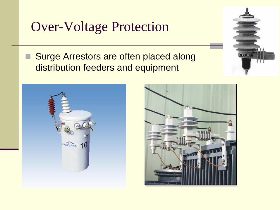
Over-Voltage Protection
Surge Arrestors are often placed along
distribution feeders and equipment

Basic Conventional Power System Layout

Electrical Power Utilization (electric load)
Utilization voltage: 120V, 208V*,
240V, 277V, 480V*, 600V*
2/3 –3/4 of electricity is consumed by motors

Demand
Changes in demand of individual customers is fast and
frequent due to load switching.
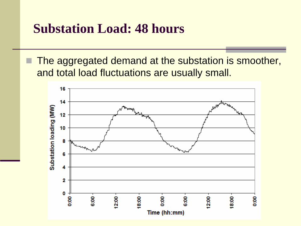
Substation Load: 48 hours
The aggregated demand at the substation is smoother,
and total load fluctuations are usually small.

MW and MVAR loading on a feeder – 4 months

System load: 24-hours
The aggregated demand on the system is even
smoother, and total load fluctuations are very small.
0
1000
2000
3000
4000
5000
6000
1 2 3 4 5 6 7 8 910 11 12 13 14 15 16 17 18 19 20 21 22 23 24
Syst
em L
oad
(MW
)
Hour of Day

System load: 4-month summer period
0
1000
2000
3000
4000
5000
60006/1/2008
6/8/2008
6/15/2008
6/22/2008
6/29/2008
7/6/2008
7/13/2008
7/20/2008
7/27/2008
8/3/2008
8/10/2008
8/17/2008
8/24/2008
8/31/2008
9/7/2008
9/14/2008
9/21/2008
9/28/2008
Time (mm/dd/yy)
Syst
em
de
man
d (
MW
)

Seasonal Load Patterns
NV Energy’s service territory loads are dominated by winter and summer patterns, with May and October as shoulder months.

Annual Load Duration Curve (LDC)
A LDC is similar to a load curve but the demand data is
ordered in descending order of magnitude, rather than
chronologically. It illustrates the relationship between
generating capacity requirements and capacity utilization.

Violent Failure of a steam-driven generator!
The explosion below was caused by a faulty valve that prevented the cutoff of
steam into the turbine when the generator went off line, leading the generator to
accelerate to over 6,000 rpm. The High speed caused parts of the generator to
tear apart. Hydrogen escaped from the cooling system, causing the explosion.

END!