controlnet fiber optic ring repeater modules - … · 2 controlnet fiber optic ring repeater...
TRANSCRIPT
Installation Instructions
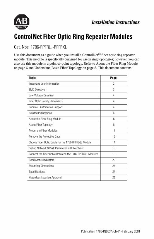
ControlNet Fiber Optic Ring Repeater ModulesCat. Nos. 1786-RPFRL, -RPFRXL
Use this document as a guide when you install a ControlNet™ fiber optic ring repeater module. This module is specifically designed for use in ring topologies; however, you can also use this module in a point-to-point topology. Refer to About the Fiber Ring Module on page 6 and Understand Basic Fiber Topology on page 8. This document contains:
Topic: Page:
Important User Information 2
EMC Directive 3
Low Voltage Directive 4
Fiber Optic Safety Statements 4
Rockwell Automation Support 4
Related Publications 6
About the Fiber Ring Module 6
About Fiber Topology 8
Mount the Fiber Modules 11
Remove the Protective Caps 13
Choose Fiber Optic Cable for the 1786-RPFR(X)L Module 14
Set up Network SMAX Parameter in RSNetWorx 18
Connect the Fiber Cable Between the 1786-RPFR(X)L Modules 18
Read Status Indicators 20
Mounting Dimensions 24
Specifications 24
Hazardous Location Approval 26
Publication 1786-IN003A-EN-P - February 2001

2 ControlNet Fiber Optic Ring Repeater Modules
This product is associated with a planning and installation guide, publication CNET-IN001A-EN-P, ControlNet Fiber Media Planning and Installation Guide.To view or download it, visit www.ab.com/manuals or www.theautomationbookstore.comYou can purchase a printed manual by:
• contacting your local distributor or Rockwell Automation representative• visiting www.theautomationbookstore.com and placing an order• calling 800.963.9548 (USA/Canada) or 001.320.725.1574 (outside USA/Canada)
Important User InformationBecause of the variety of uses for the products described in this publication, those responsible for the application and use of this control equipment must satisfy themselves that all necessary steps have been taken to assure that each application and use meets all performance and safety requirements, including any applicable laws, regulations, codes and standards.
The illustrations, charts, sample programs and layout examples shown in this guide are intended solely for purposes of example. Since there are many variables and requirements associated with any particular installation, Allen-Bradley does not assume responsibility or liability (to include intellectual property liability) for actual use based upon the examples shown in this publication.
Allen-Bradley publication SGI-1.1, Safety Guidelines for the Application, Installation and Maintenance of Solid-State Control (available from your local Allen-Bradley office), describes some important differences between solid-state equipment and electromechanical devices that should be taken into consideration when applying products such as those described in this publication.
Reproduction of the contents of this copyrighted publication, in whole or part, without written permission of Rockwell Automation, is prohibited.
TIPThroughout this manual, when we refer to both the 1786-RPFRL and 1786-RPFRXL modules, we show the modules’ combined catalog number in this way:
1786-RPFR(X)L
Publication 1786-IN003A-EN-P - February 2001
ControlNet Fiber Optic Ring Repeater Modules 3
Throughout this manual we use notes to make you aware of safety considerations:
Attention statements help you to:
• identify a hazard
• avoid a hazard
• recognize the consequences
Allen-Bradley is a trademark of Rockwell Automation
European Communities (EC) Directive ComplianceIf this product has the CE mark it is approved for installation within the European Union and EEA regions. It has been designed and tested to meet the following directives.
EMC DirectiveThis product is tested to meet the Council Directive 89/336/EC Electromagnetic Compatibility (EMC) by applying the following standards, in whole or in part, documented in a technical construction file:
• EN 50081-2 EMC — Generic Emission Standard, Part 2 — Industrial Environment
• EN 50082-2 EMC — Generic Immunity Standard, Part 2 — Industrial Environment
This product is intended for use in an industrial environment.
ATTENTION
!Identifies information about practices or circumstances that can lead to personal injury or death, property damage or economic loss
IMPORTANT Identifies information that is critical for successful application and understanding of the product.
Publication 1786-IN003A-EN-P - February 2001
4 ControlNet Fiber Optic Ring Repeater Modules
Low Voltage DirectiveThis product is tested to meet Council Directive 73/23/EEC Low Voltage, by applying the safety requirements of EN 61131-2 Programmable Controllers, Part 2 - Equipment Requirements and Tests. For specific information required by EN 61131-2, see the appropriate sections in this publication, as well as the Allen-Bradley publication Industrial Automation Wiring and Grounding Guidelines, publication 1770-4.1.
This equipment is classified as open equipment and must be mounted in an enclosure during operation to provide safety protection.
Fiber Optic Safety Statements
Rockwell Automation SupportRockwell Automation offers support services worldwide, with over 75 sales/support offices, over 500 authorized distributors, and 260 authorized systems integrators located throughout the United States alone, plus Rockwell Automation
ATTENTION
!Do not look directly into the fiber ports. Light levels will cause damage to your eyesight.
ATTENTION
!
Hazardous areas require the use of specifically designed products. This product is designed for Class I, Division 2 hazardous environments, and nonhazardous environments only. Allen-Bradley provides similar products which are intrinsically safe and are suitable for more hazardous environments. Use the appropriate products that are designed for the specific hazardous environments that your installation requires.
In intrinsically safe applications, consult with your local safety coordinator, and publication CNET-IN003A-US-P, ControlNet EX Media Planning and Installation Manual, because you need specific products on both ends of the fiber link.
Publication 1786-IN003A-EN-P - February 2001
ControlNet Fiber Optic Ring Repeater Modules 5
representatives in every major country around the world. Contact your local Rockwell Automation representative for:
• sales and order support
• product technical training
• warranty support
• support service agreements
Obtain Pre-Sales Product SupportIf you need to contact Rockwell Automation for pre-sales product support, try one of the following methods:
• Call your local Rockwell Automation representative
• Network pre-sales support line, 1.440.646.3638 (3NET)
• Pre-Sales e-mail, [email protected]
Obtain Technical Product SupportIf you need to contact Rockwell Automation for technical assistance, try one of the following methods:
Type of technical support: Access at:
Personalized Service Call your local Rockwell Automation representative
Post-sales Technical Support 1.440.646.5800
Email your questions to [email protected]
Internet site www.ab.com
Publication 1786-IN003A-EN-P - February 2001
6 ControlNet Fiber Optic Ring Repeater Modules
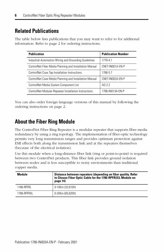
Related PublicationsThe table below lists publications that you may want to refer to for additional information. Refer to page 2 for ordering instructions.
You can also order foreign language versions of this manual by following the ordering instructions on page 2.
About the Fiber Ring ModuleThe ControlNet Fiber Ring Repeater is a modular repeater that supports fiber media redundancy by using a ring topology. The implementation of fiber-optic technology permits very long transmission ranges and provides optimum protection against EMI effects both along the transmission link and at the repeaters themselves (because of the electrical isolation).
Use this module when a long-distance fiber link (ring or point-to-point) is required between two ControlNet products. This fiber link provides ground isolation between nodes and is less susceptible to noisy environments than traditional copper media.
Publication Publication Number
Industrial Automation Wiring and Grounding Guidelines 1770-4.1
ControlNet Fiber Media Planning and Installation Manual CNET-IN001A-EN-P
ControlNet Coax Tap Installation Instructions 1786-5.7
ControlNet Coax Media Planning and Installation Manual CNET-IN002A-EN-P
ControlNet Media System Component List AG-2.2
ControlNet Modular Repeater Installation Instructions 1786-IN013A-EN-P
Module Distance between repeaters (depending on fiber quality. Refer to Choose Fiber Optic Cable for the 1786-RPFR(X)L Module on page 14)
1786-RPFRL 0-10Km (32,810ft)
1786-RPFRXL 0-20Km (65,620ft)
Publication 1786-IN003A-EN-P - February 2001
ControlNet Fiber Optic Ring Repeater Modules 7
The modules provide:
• two fiber channels
• activity LED indicators for each fiber channel
IMPORTANT The distance between repeaters that can be supported is dependent on the quality of the fiber, number of splices, and connectors. The total loss of the fiber link must be less than 15dB for the 1786-RPFRL and 10.5dB for the 1786-RPFRXL.
The total size of the ring or length of the ControlNet network is limited by the ControlNet protocol to 20Km or less. Refer to Determine Maximum Network Length on page 15 for more information.
IMPORTANT The 1786-RPFR(X)L modules cannot be used in a ring topology to achieve network redundancy. If your application requires redundancy, use a linear topology.
TIPYou must use an adapter module (1786-RPA) with the 1786-RPFR(X)L module.
Publication 1786-IN003A-EN-P - February 2001

8 ControlNet Fiber Optic Ring Repeater Modules
Figure 1 Module Components
About Fiber TopologyThe topology examples in this section are for illustration purposes only. Refer to the ControlNet Fiber Media Planning and Installation Guide, publication CNET-IN001B-EN-P, for details.
Understand Basic Fiber TopologyThe 1786-RPFRXL module is used to create a redundant optical link between segments. When used in a ring topology, a media failure between two 1786-RPFRXL modules will not impact the communication link.
The repeaters detect the failure of an optical link. When a failure occurs, the affected channel port LED will be either:
• red, indicating a faulty link, or
• flashing green/off, indicating no network activity is present
We recommend that you install the duplex optical cables of the two optical channels along different routes.
The fiber repeater consists of a module hub adapter (1786-RPA) and 1 to 4 fiber repeater modules (1786-RPFS, -RPFM, -RPFRL, and -RPFRXL).
In addition to using the fiber repeater in a ring topology, you can also use it:
• to extend the total length of your segment
• to create a star configuration (multiple directions from one point)
• for installations in hazardous areas
The number of fiber repeaters and cable length total limit depends on your network topology. A fiber optic ring may contain up to 20 member modules, depending on
Indicators
Protective caps
Channel 1 fiber port
Module locking tab Channel 2 fiber port
Right-side backplane connector with protective cover
The left side of the modules (not shown here) also contains a backplane connector 42546
Publication 1786-IN003A-EN-P - February 2001

ControlNet Fiber Optic Ring Repeater Modules 9
the application. For more information on topology application rules in relation to fiber rings, refer to the ControlNet Fiber Media Planning and Installation Guide, publication CNET-IN001A-EN-P, for details.
Example Topology ApplicationsThe following figures show applications using example topologies.
Figure 2 Fiber Ring Topology ExampleUse this configuration to achieve redundancy over a long distance (not available when you use traditional copper media).
TIPRedundant power supplies help to increase reliability. The power supplies should be powered from separate mains.
31219-M
1786-RPA 1786-RPA 1786-RPA1786-RPFR(X)L 1786-RPFR(X)L 1786-RPFR(X)L
CH 1 CH2 CH 1 CH2 CH 1 CH2
RX TX
On all 1786-RPFRL or -RPFRXL modules, the left-most connector is the RX port; the right-most connector is the TX port.
Publication 1786-IN003A-EN-P - February 2001
10 ControlNet Fiber Optic Ring Repeater Modules
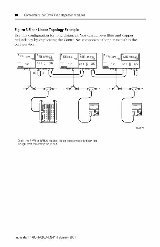
Figure 3 Fiber Linear Topology ExampleUse this configuration for long distances. You can achieve fiber and copper redundancy by duplicating the ControlNet components (copper media) in the configuration.
31218-M
1786-RPA 1786-RPA 1786-RPA1786-RPFR(X)L 1786-RPFR(X)L 1786-RPFR(X)L
CH 1 CH2 CH 1 CH2 CH 1 CH2
RX TX
On all 1786-RPFRL or -RPFRXL modules, the left-most connector is the RX port; the right-most connector is the TX port.
Publication 1786-IN003A-EN-P - February 2001
ControlNet Fiber Optic Ring Repeater Modules 11
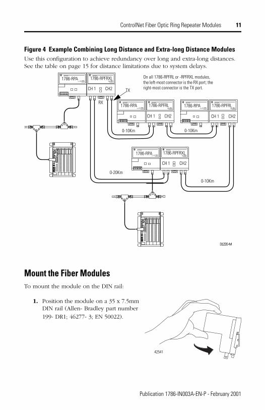
Figure 4 Example Combining Long Distance and Extra-long Distance ModulesUse this configuration to achieve redundancy over long and extra-long distances. See the table on page 15 for distance limitations due to system delays.
Mount the Fiber ModulesTo mount the module on the DIN rail:
1. Position the module on a 35 x 7.5mm DIN rail (Allen- Bradley part number
199- DR1; 46277- 3; EN 50022).
31220-M
1786-RPA
1786-RPFRXL
1786-RPFRL
CH 1 CH2
CH 1 CH2
CH 1 CH2
1786-RPFRL
CH 1 CH2
1786-RPA
1786-RPA
1786-RPA
1786-RPFRXL
0-10Km
0-10Km 0-10Km
0-20Km
RX
TX
On all 1786-RPFRL or -RPFRXL modules, the left-most connector is the RX port; the right-most connector is the TX port.
42541
Publication 1786-IN003A-EN-P - February 2001

12 ControlNet Fiber Optic Ring Repeater Modules
2. Hook the lip on the rear of the module onto the top of the DIN rail, and rotate the module onto the rail.
3. Press the module onto the DIN rail until flush.
The locking tab should snap into position and lock the module to the DIN rail.
4. If the module does not snap into position, use a screwdriver or similar device to retract the locking tab while pressing the module flush onto the DIN rail. Release the locking tab to lock the module in place. If necessary, push the locking tab to lock.
5. Remove the protective backplane cap as shown on page 13.
6. Once the modules are attached to the DIN rail, slide them together to mate the repeater adapter with the repeater module.
42542
42543
42632
Publication 1786-IN003A-EN-P - February 2001

ControlNet Fiber Optic Ring Repeater Modules 13
7. Connect the fiber cable as described on page 18.
Remove the Protective Caps
1. Remove the protective caps from the fiber ports that you are going to use.
2. Save the caps for future use.
The left side of the module (not shown here) also contains a backplane connector
.
ATTENTION
!Be certain that the adapter and repeater modules are secured together with DIN rail anchors. Failure to do so may result in the loss of communications and/ or cause damage to the modules. The total number of modules that can be attached to the repeater adapter (1786-RPA) cannot exceed four or the total power consumption of the modules can not exceed 1.6A @ 5VDC, whichever comes first.
IMPORTANT If you exceed the module or power limit, you may cause damage to the repeater adapter and modules.
If you plan: Then:
not to use a channel and the module is connected to the network
attach a small section of fiber cable to create a jumper. This is not required for module operation, but turns all status LEDs green.
DIN rail
Protective backplane cap
Protective cap (used during shipping)
Publication 1786-IN003A-EN-P - February 2001
14 ControlNet Fiber Optic Ring Repeater Modules
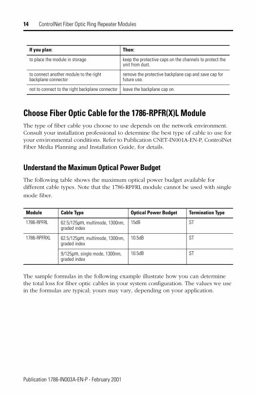
Choose Fiber Optic Cable for the 1786-RPFR(X)L ModuleThe type of fiber cable you choose to use depends on the network environment. Consult your installation professional to determine the best type of cable to use for your environmental conditions. Refer to Publication CNET-IN001A-EN-P, ControlNet Fiber Media Planning and Installation Guide, for details.
Understand the Maximum Optical Power BudgetThe following table shows the maximum optical power budget available for different cable types. Note that the 1786-RPFRL module cannot be used with single
mode fiber.
The sample formulas in the following example illustrate how you can determine the total loss for fiber optic cables in your system configuration. The values we use in the formulas are typical; yours may vary, depending on your application.
to place the module in storage keep the protective caps on the channels to protect the unit from dust.
to connect another module to the right backplane connector
remove the protective backplane cap and save cap for future use.
not to connect to the right backplane connector leave the backplane cap on.
Module Cable Type Optical Power Budget Termination Type
1786-RPFRL 62.5/125µm, multimode, 1300nm, graded index
15dB ST
1786-RPFRXL 62.5/125µm, multimode, 1300nm, graded index
10.5dB ST
9/125µm, single mode, 1300nm, graded index
10.5dB ST
If you plan: Then:
Publication 1786-IN003A-EN-P - February 2001

ControlNet Fiber Optic Ring Repeater Modules 15
Determine Maximum Network LengthThe quality of the fiber cable determines the maximum distance between modules in a networked system. The delay in the system (described in the following table) determines the maximum length you can achieve with your network.
The worst-case delay (between any nodes) must be less than 121 µs. The table below lists worst-case delays for physical layer components.
EXAMPLE Determining total loss for fiber optic cables
The total loss of the fiber optic cable between two modules must not exceed the optical power budget. The total loss is the sum of each connector loss plus the loss of the fiber plus the loss associated with the splices in the system, if any. The total loss can be determined as follows:
total loss = [(loss per connector) x (the number of connectors)] + [(loss per Km of fiber) x (Km of fiber)] + [(other losses)]
For example, with 2 connectors, each having 0.3dB of loss, 10 Km of multimode fiber with a loss of 1dB/Km, and no splices, the total loss is 10.6dB. See the following formula:
total loss = [(0.3dB x 2) + (1dB/Km x 10 Km)] total loss = 10.6dB
This fiber optic cable is acceptable for use between two 1786-RPFRL modules because the total loss is less than the optical power budget of 15dB. However, this cable could not be used with the 1786-RPFRXL module because the total loss exceeds the optical power budget of 10.5dB.
component delay
coaxial cable 4.3ns/m
fiber 5.01ns/m
1786-RPA 901ns
1786-RPFM 94ns
1786-RPFS 153ns
1786-RPCD 94ns
1786-RPFRL1786-RPFRXL
300ns
Publication 1786-IN003A-EN-P - February 2001
16 ControlNet Fiber Optic Ring Repeater Modules
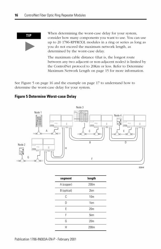
See Figure 5 on page 16 and the example on page 17 to understand how to determine the worst-case delay for your system.
Figure 5 Determine Worst-case Delay
TIPWhen determining the worst-case delay for your system, consider how many components you want to use. You can use up to 20 1786-RPFR(X)L modules in a ring or series as long as you do not exceed the maximum network length, as determined by the worst-case delay.
The maximum cable distance (that is, the longest route between any two adjacent or non-adjacent nodes) is limited by the ControlNet protocol to 20Km or less. Refer to Determine Maximum Network Length on page 15 for more information.
segment length
A (copper) 200m
B (optical) 2km
C 10m
D 1km
E 20m
F 5km
G 20m
H 200m
31216-M
Node 1
Node 2
Node 3
Node 4
A
B
C
D
E
FG
H
Publication 1786-IN003A-EN-P - February 2001
ControlNet Fiber Optic Ring Repeater Modules 17
EXAMPLE Determining worst-case delay
See Figure 5 on page 16.
To determine the worst-case delay in a ring topology, first disregard the shortest fiber segment in the system.
In this diagram, the shortest segment is segment H, the 200m fiber. Remove segment H. You will see that the worst-case delay is between nodes 1 and 2.
You must account for worst-case delays introduced by physical media when setting up the media configuration screen in RSNetWorx. System delays will affect the slot time RSNetWorx calculates. If too many components with too great a delay are entered into RSNetWorx, the slot time will be too large. This affects system performance and artificially limits network length. If you do not account for all media components in the worst-case delay path, the slot time may be too small. Erratic network operation will result. Refer to the documentation supplied with RSNetWorx for information on using it.
In this example, you would enter the total length of all media components between nodes 1 and 2 into RSNetWorx. The totals of the components between nodes 1 and 2 are as follows:
coax media: 200m + 20m = 220m
fiber media: 2Km + 1Km + 5Km = 8Km
1786-RPA module: 1 (at node 1) + 1 (at node 2) = 2 x RPA delay
1786-RPFR(X)L module: 4
This example shows you in a simple way how to account for system delays. However, the calculation can be fairly complex, depending on the total number of components in your worst-case delay path. For example, 500m of fiber at 5.01ns/m has more delay than 550m of coaxial cable at 4.3ns/m. Remember, the total delay, not the total length, is more important in configuring your network for maximum efficiency.
Publication 1786-IN003A-EN-P - February 2001
18 ControlNet Fiber Optic Ring Repeater Modules
Publication 1786-IN003A-EN-P - February 2001
Set up Network SMAX Parameter in RSNetWorxYou must set up the SMAX parameter in RSNetWorx for use with the 1786-RPFR(X)L module. The SMAX parameter sets the maximum scheduled node address on a ControlNet network. Refer to the documentation supplied with RSNetWorx for more information on using it. Keep these points in mind when setting up the SMAX parameter.
• SMAX must be set to one greater than the actual number of nodes on a network. For example, on a network with 49 nodes that transmit in scheduled time, you must set SMAX to 50.
• The nodes may be numbered in any order, but at least 1 node number must be missing. For example:
– from 1-49, or
– from 1-25 and 27 to 50, or
– from 1-44 and 46-50
This limits the maximum size of the network to 98 nodes when using 1786-RPFR(X)L modules.
Connect the Fiber Cable Between the 1786-RPFR(X)L Modules
Terminate the CableBefore you can connect the cable to the module you will need to terminate the cable. Termination is simply the process of attaching a connector to the ends of the fiber cable. We recommend that you use a quality kit such as the Corning Cable Systems Termination Kit with the UniCam ST connectors. The Corning Cable Systems Termination Kit has proven to be a simple and reliable method to terminate fiber
cable. For more information, visit www.corningcablesystems.com.
IMPORTANT Avoid splicing your cable too much. Connectors can cause considerable attenuation. Splices and connectors limit the maximum length of your system. Be sure to check the attenuation of different cable sections after the cable is installed.

ControlNet Fiber Optic Ring Repeater Modules 19
Connect the CableA simple way to connect cables is to use the tracer on the cable to identify and follow the cable throughout your system. A tracer is simply one of the two wires on the duplex cable that is either:
• printed with the cable legend, or
• ribbed
In the following procedure (beginning on page 20), we tell you how to connect the cable between the fiber modules by making a simple “criss-cross” connection. To do this, you will connect the cables between modules from the Receive (RX) end of one channel to the Transmit (TX) end of the other module as shown in the following diagram:
TIPConsult your local distributor for attenuation specifications prior to purchasing your fiber media components.
TIPChannels 1 and 2 on the module are identical. Channel 1 of a module can be connected to either channel of another module.
TX TXRXRX
Publication 1786-IN003A-EN-P - February 2001
20 ControlNet Fiber Optic Ring Repeater Modules
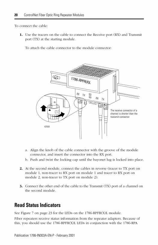
To connect the cable:
1. Use the tracers on the cable to connect the Receive port (RX) and Transmit port (TX) at the starting module.
To attach the cable connector to the module connector:
a. Align the knob of the cable connector with the groove of the module connector, and insert the connector into the RX port.
b. Push and twist the locking cap until the bayonet lug is locked into place.
2. At the second module, connect the cables in reverse (tracer to TX port on module 1, non-tracer to RX port on module 1 and tracer to RX port on module 2, non-tracer to TX port on module 2).
3. Connect the other end of the cable to the Transmit (TX) port of a channel on the second module.
Read Status IndicatorsSee Figure 7 on page 23 for the LEDs on the 1786-RPFR(X)L module.
Fiber repeaters receive status information from the repeater adapters. Because of this, you should use the 1786-RPFR(X)L LEDs in conjunction with the 1786-RPA
1786-RPFR(X)L
The receive connector of a channel is shorter than the transmit connector
RX TXRX TX
42550
Publication 1786-IN003A-EN-P - February 2001
ControlNet Fiber Optic Ring Repeater Modules 21
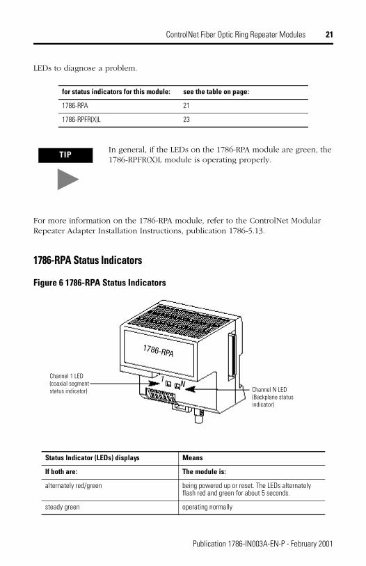
LEDs to diagnose a problem.
For more information on the 1786-RPA module, refer to the ControlNet Modular Repeater Adapter Installation Instructions, publication 1786-5.13.
1786-RPA Status Indicators
Figure 6 1786-RPA Status Indicators
for status indicators for this module: see the table on page:
1786-RPA 21
1786-RPFR(X)L 23
TIPIn general, if the LEDs on the 1786-RPA module are green, the 1786-RPFR(X)L module is operating properly.
Status Indicator (LEDs) displays Means
If both are: The module is:
alternately red/green being powered up or reset. The LEDs alternately flash red and green for about 5 seconds.
steady green operating normally
Channel N LED (Backplane status indicator)
Channel 1 LED (coaxial segment status indicator)
1786-RPA
1N
Publication 1786-IN003A-EN-P - February 2001
22 ControlNet Fiber Optic Ring Repeater Modules
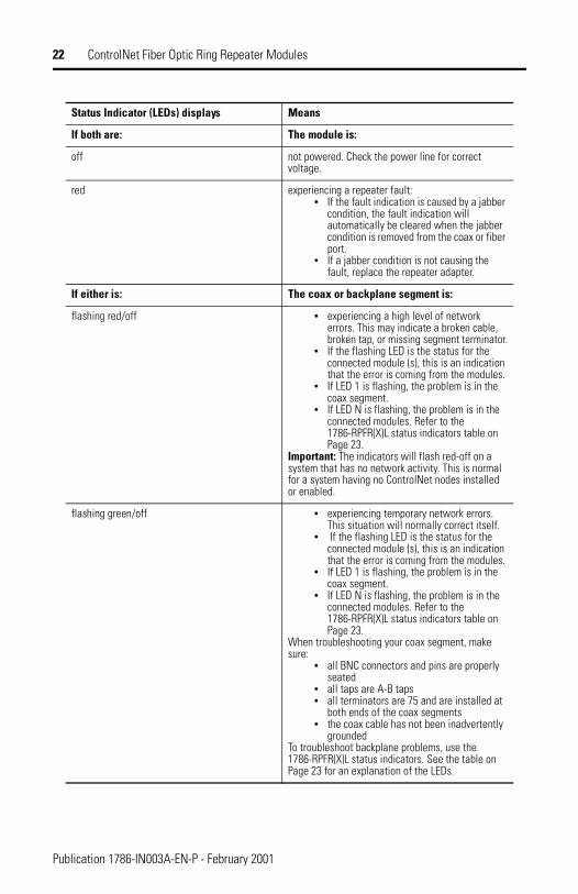
Status Indicator (LEDs) displays Means
If both are: The module is:
off not powered. Check the power line for correct voltage.
red experiencing a repeater fault:• If the fault indication is caused by a jabber
condition, the fault indication will automatically be cleared when the jabber condition is removed from the coax or fiber port.
• If a jabber condition is not causing the fault, replace the repeater adapter.
If either is: The coax or backplane segment is:
flashing red/off • experiencing a high level of network errors. This may indicate a broken cable, broken tap, or missing segment terminator.
• If the flashing LED is the status for the connected module (s), this is an indication that the error is coming from the modules.
• If LED 1 is flashing, the problem is in the coax segment.
• If LED N is flashing, the problem is in the connected modules. Refer to the 1786-RPFR(X)L status indicators table on Page 23.
Important: The indicators will flash red-off on a system that has no network activity. This is normal for a system having no ControlNet nodes installed or enabled.
flashing green/off • experiencing temporary network errors. This situation will normally correct itself.
• If the flashing LED is the status for the connected module (s), this is an indication that the error is coming from the modules.
• If LED 1 is flashing, the problem is in the coax segment.
• If LED N is flashing, the problem is in the connected modules. Refer to the 1786-RPFR(X)L status indicators table on Page 23.
When troubleshooting your coax segment, make sure:
• all BNC connectors and pins are properly seated
• all taps are A-B taps• all terminators are 75 and are installed at
both ends of the coax segments• the coax cable has not been inadvertently
groundedTo troubleshoot backplane problems, use the 1786-RPFR(X)L status indicators. See the table on Page 23 for an explanation of the LEDs.
Publication 1786-IN003A-EN-P - February 2001

ControlNet Fiber Optic Ring Repeater Modules 23
1786-RPFR(X)L Status Indicators
Figure 7 1786-RPFR(X)L Status Indicators
Status Indicator (LEDs) displays Means
off Repeater not connected to power supply.
green Repeater is running without network errors.
flashing green/off No data activity on network. If the cable is attached:• ensure that the Receive (Rx) channel is connected
to the Transmit (Tx) channel on both modules• check for broken fiber.
flashing red/off Module is powered, but not ready for operation. This state should also occur during module reset and last for approximately 5 seconds.
intermittent red As more data errors are detected the frequency of the flashing red increases until a solid red displays.
red Excessive receive signal distortion.• Be certain that you are using the correct fiber type
for your module.• Check fiber length and attenuation to ensure that it
is within specification.• Replace the downstream 1786-RPFRL module on
the channel having the intermittently flashing red LED.
• Be certain that your total network length is not out of specification. See Figure 4 on page 11 for network lengths.
• Be certain that SMAX is correctly defined in RSNetWorx. Refer to Set up Network SMAX Parameter in RSNetWorx on page 18.
Channel 2 LED
Channel 1 LED
42548
1786-RPFR(X)L
RX TXRX TX
Publication 1786-IN003A-EN-P - February 2001

24 ControlNet Fiber Optic Ring Repeater Modules
Mounting Dimensions
Figure 8 Mounting Dimensions
Specifications
Item Description
Communication Rate 5M bits/s
Backplane Current consumption a maximum of 400mA at 5V dc, Class 2 operating power supplied by catalog number 1786-RPA(1)
Min 4.7V Max 5.3V
Optical Power Budget See Optical Power Budget table on page 14
OperatingTemperature 0 to 60o C (32 to 125o F)
Storage Temperature -40 to 85o C (-40 to 165o F)
Relative Humidity 5 to 95% non-condensing
4.20 in.(107 mm)
2.76 in.(69 mm)
4.250 in.(108 mm)
4.0 in.(100 mm)
42635
3.6 in.(90 mm)
Publication 1786-IN003A-EN-P - February 2001
ControlNet Fiber Optic Ring Repeater Modules 25
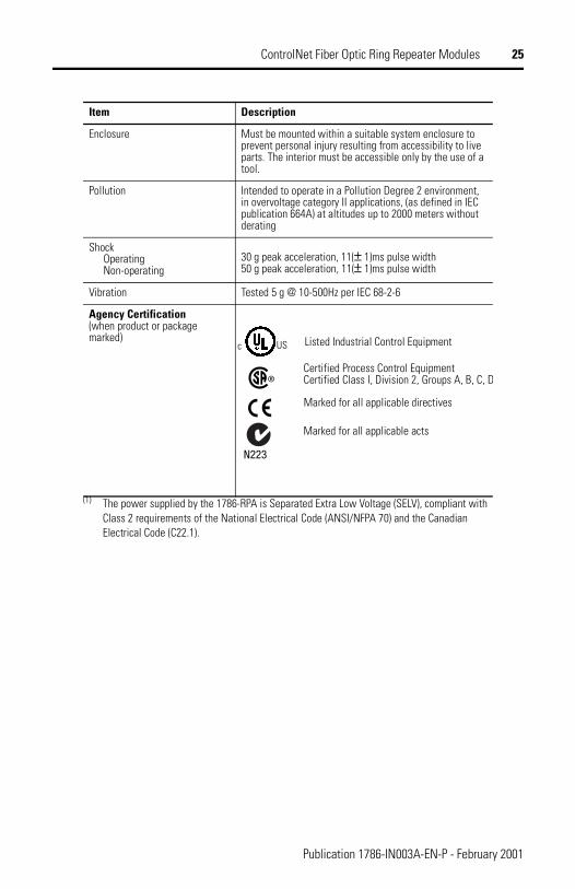
Enclosure Must be mounted within a suitable system enclosure to prevent personal injury resulting from accessibility to live parts. The interior must be accessible only by the use of a tool.
Pollution Intended to operate in a Pollution Degree 2 environment, in overvoltage category II applications, (as defined in IEC publication 664A) at altitudes up to 2000 meters without derating
Shock OperatingNon-operating
30 g peak acceleration, 11(± 1)ms pulse width50 g peak acceleration, 11(± 1)ms pulse width
Vibration Tested 5 g @ 10-500Hz per IEC 68-2-6
Agency Certification(when product or package marked)
(1) The power supplied by the 1786-RPA is Separated Extra Low Voltage (SELV), compliant with Class 2 requirements of the National Electrical Code (ANSI/NFPA 70) and the Canadian Electrical Code (C22.1).
Item Description
Listed Industrial Control Equipment
N223
Certified Process Control EquipmentCertified Class l, Division 2, Groups A, B, C, D
Marked for all applicable acts
Marked for all applicable directives
USc
Publication 1786-IN003A-EN-P - February 2001

26 ControlNet Fiber Optic Ring Repeater Modules
Hazardous Location ApprovalThe following information applies when operating this equipment in hazardous locations:
Products marked “CL I, DIV 2, GP A, B, C, D” are suitable for use in Class I Division 2 Groups A, B, C, D, Hazardous Locations and nonhazardous locations only. Each product is supplied with markings on the rating nameplate indicating the hazardous location temperature code. When combining products within a system, the most adverse temperature code (lowest “T” number) may be used to help determine the overall temperature code of the system. Combinations of equipment in your system are subject to investigation by the local authority that has jurisdiction at the time of installation.
EXPLOSION HAZARD –
• Do not disconnect equipment unless power has been removed or the area is known to be nonhazardous.
• Do not disconnect connections to this equipment unless power has been removed or the area is known to be nonhazardous. Secure any external connections that mate to this equipment by using screws, sliding latches, threaded connectors, or other means provided with this product.
• Substitution of components may impair suitability for Class I, Division 2.• If this product contains batteries, they must only be changed in an area known to
be nonhazardous.
Informations sur l’utilisation de cet équipementen environnements dangereux:
Les produits marqués «CL I, DIV 2, GP A, B, C, D» ne conviennent qu’à une utilisation en environnements de Classe I Division 2 Groupes A, B, C, D dangereux et non dangereux. Chaque produit est livré avec des marquages sur sa plaque d’identification qui indiquent le code de température pour les environnements dangereux. Lorsque plusieurs produits sont combinés dans un système, le code de température le plus défavorable (code de température le plus faible) peut être utilisé pour déterminer le code de température global du système. Les combinaisons d’équipements dans le système sont sujettes à inspection par les autorités locales qualifiées au moment de l’installation.
RISQUE D’EXPLOSION –
• Couper le courant ou s’assurer que l’environnement est classé non dangereux avant de débrancher l'équipement.
• Couper le courant ou s'assurer que l’environnement est classé non dangereux avant de débrancher les connecteurs. Fixer tous les connecteurs externes reliés à cet équipement à l'aide de vis, loquets coulissants, connecteurs filetés ou autres moyens fournis avec ce produit.
• La substitution de composants peut rendre cet équipement inadapté à une utilisation en environnement de Classe 1, Division 2.
• S’assurer que l’environnement est classé non dangereux avant de changer les piles.
Publication 1786-IN003A-EN-P - February 2001
ControlNet Fiber Optic Ring Repeater Modules 27
Notes:
Publication 1786-IN003A-EN-P - February 2001

Publication 1786-IN003A-EN-P - February 2001 PN 957308-81© 2001 Rockwell International Corporation. Printed in Germany.