controllogix sil2 system configuration using sil2 add-on … · 2015-10-22 · about this chapter...
TRANSCRIPT

Application Technique
(Catalog Numbers 1756 and 1492)
ControlLogix SIL2 System ConfigurationUsing SIL2 Add-On Instructions

Important User InformationSolid state equipment has operational characteristics differing from those of electromechanical equipment. Safety Guidelines for the Application, Installation and Maintenance of Solid State Controls (publication SGI-1.1 available from your local Rockwell Automation sales office or online at http://literature.rockwellautomation.com) describes some important differences between solid state equipment and hard-wired electromechanical devices. Because of this difference, and also because of the wide variety of uses for solid state equipment, all persons responsible for applying this equipment must satisfy themselves that each intended application of this equipment is acceptable.
In no event will Rockwell Automation, Inc. be responsible or liable for indirect or consequential damages resulting from the use or application of this equipment.
The examples and diagrams in this manual are included solely for illustrative purposes. Because of the many variables and requirements associated with any particular installation, Rockwell Automation, Inc. cannot assume responsibility or liability for actual use based on the examples and diagrams.
No patent liability is assumed by Rockwell Automation, Inc. with respect to use of information, circuits, equipment, or software described in this manual.
Reproduction of the contents of this manual, in whole or in part, without written permission of Rockwell Automation, Inc., is prohibited.
Throughout this manual, when necessary, we use notes to make you aware of safety considerations.
Allen-Bradley, ControlLogix, Logix5000, RSLogix 5000, RSNetWorx for ControlNet, Rockwell Automation, and TechConnect are trademarks of Rockwell Automation, Inc.
Trademarks not belonging to Rockwell Automation are property of their respective companies.
WARNINGIdentifies information about practices or circumstances that can cause an explosion in a hazardous environment, which may lead to personal injury or death, property damage, or economic loss.
IMPORTANT Identifies information that is critical for successful application and understanding of the product.
ATTENTION Identifies information about practices or circumstances that can lead to personal injury or death, property damage, or economic loss. Attentions help you identify a hazard, avoid a hazard, and recognize the consequence
SHOCK HAZARD Labels may be on or inside the equipment, for example, a drive or motor, to alert people that dangerous voltage may be present.
BURN HAZARD Labels may be on or inside the equipment, for example, a drive or motor, to alert people that surfaces may reach dangerous temperatures.

Table of Contents
PrefaceAbout This Publication . . . . . . . . . . . . . . . . . . . . . . . . . . . . . 9Who Should Use This Publication . . . . . . . . . . . . . . . . . . . . . 9Conventions . . . . . . . . . . . . . . . . . . . . . . . . . . . . . . . . . . . . . 9About SIL . . . . . . . . . . . . . . . . . . . . . . . . . . . . . . . . . . . . . . . 9Additional Resources. . . . . . . . . . . . . . . . . . . . . . . . . . . . . . 10
Chapter 1Fault-tolerant System Configuration
About This Chapter . . . . . . . . . . . . . . . . . . . . . . . . . . . . . . . 11Fault Tolerance and the ControlLogix System . . . . . . . . . . . . 11
ControlLogix System SIL2 Configurations . . . . . . . . . . . . 11About Fault-tolerant Systems . . . . . . . . . . . . . . . . . . . . . 12Fault-tolerant Compared to Other SIL2 Configurations . . . 12
Fault-tolerant System Configuration . . . . . . . . . . . . . . . . . . . 14Remote I/O Configuration . . . . . . . . . . . . . . . . . . . . . . . 14
The Complete ControlLogix Fault-tolerant System. . . . . . . . . 18Additional Resources. . . . . . . . . . . . . . . . . . . . . . . . . . . . . . 19
Chapter 2Fault-tolerant System Hardware About This Chapter . . . . . . . . . . . . . . . . . . . . . . . . . . . . . . . 21
Approved I/O Modules and Termination Boards . . . . . . . . . 21About the Specialized Termination Boards . . . . . . . . . . . 22
1756-IB32 DC Input Termination Board Features . . . . . . . . . 22Normal Operation of 1756-IB32 DC Input Termination Board. . . . . . . . . . . . . . . . . . . . . . . . . . . . . 231756-IB32 DC Input Termination Board and Transition Tests . . . . . . . . . . . . . . . . . . . . . . . . . . . . . . . 24
1756-IF16 Analog Input Termination Board . . . . . . . . . . . . . 26Normal Operation of the 1756-IF16 Analog Input Termination Board. . . . . . . . . . . . . . . . . . . . . . . . . . . . . 27One-sensor or Two-sensor Wiring Option. . . . . . . . . . . . 291756-IF16 Module Pair Reference Tests . . . . . . . . . . . . . . 30
1756-OB16D Diagnostic Output Termination Board Features 33Normal Operation of the 1756-OB16D Diagnostic Output Termination Board. . . . . . . . . . . . . . . . . . . . . . . . . . . . . 34Diagnostic Tests and the 1756-OB16D Output Termination Board. . . . . . . . . . . . . . . . . . . . . . . . . . . . . 35
Termination Board Relay Control . . . . . . . . . . . . . . . . . . . . . 361756-IB32 Input Termination Board Relay Control. . . . . . 361756-IF16 Analog Input-Termination Board Switch Control . . . . . . . . . . . . . . . . . . . . . . . . . . . . . . . . 371756-OB16D Output Termination Board Relay Control . . 38
Input Module Diagnostic Test Control . . . . . . . . . . . . . . . . . 40Hardware and Programming . . . . . . . . . . . . . . . . . . . . . . . . 40Additional Resources. . . . . . . . . . . . . . . . . . . . . . . . . . . . . . 41
3Publication 1756-AT012A-EN-P - November 2008 3

Table of Contents
Chapter 3Fault-tolerant Program Elements About This Chapter . . . . . . . . . . . . . . . . . . . . . . . . . . . . . . . 43
Overview of the Program Elements . . . . . . . . . . . . . . . . . . . 43Main Routine . . . . . . . . . . . . . . . . . . . . . . . . . . . . . . . . . 43SIL2 Add-On Instructions . . . . . . . . . . . . . . . . . . . . . . . . 44Diagnostic Features of Add-On Instruction Programming. 45
States of the System . . . . . . . . . . . . . . . . . . . . . . . . . . . . . . 46Normal State . . . . . . . . . . . . . . . . . . . . . . . . . . . . . . . . . 46Test State. . . . . . . . . . . . . . . . . . . . . . . . . . . . . . . . . . . . 461oo1 State . . . . . . . . . . . . . . . . . . . . . . . . . . . . . . . . . . . 47Faulted State . . . . . . . . . . . . . . . . . . . . . . . . . . . . . . . . . 48
IB32_SIL2_Pair Instruction . . . . . . . . . . . . . . . . . . . . . . . . . . 49Normal Operation - 1756-IB32 Module Pair. . . . . . . . . . . 49Test - 1756-IB32 Module Pair . . . . . . . . . . . . . . . . . . . . . 501oo1 - 1756-IB32 Module Pair . . . . . . . . . . . . . . . . . . . . 50
IF16_SIL2_Pair Instruction . . . . . . . . . . . . . . . . . . . . . . . . . . 51Normal Operation - 1756-IF16 Module Pair . . . . . . . . . . . 51Test - 1756-IF16 Module Pair . . . . . . . . . . . . . . . . . . . . . 521oo1 - 1756-IF16 Module Pair. . . . . . . . . . . . . . . . . . . . . 52
IF16_RefCal Instruction . . . . . . . . . . . . . . . . . . . . . . . . . . . . 53OB16D_SIL2 Instruction . . . . . . . . . . . . . . . . . . . . . . . . . . . 54
Normal Operation - 1756-OB16D . . . . . . . . . . . . . . . . . . 541oo1 - 1756-OB16D . . . . . . . . . . . . . . . . . . . . . . . . . . . . 55
The Fault-tolerant Program . . . . . . . . . . . . . . . . . . . . . . . . . 55Additional Resources. . . . . . . . . . . . . . . . . . . . . . . . . . . . . . 56
4 Publication 1756-AT012A-EN-P - November 2008

Table of Contents
Chapter 4Configuring the Fault-tolerant System
About This Chapter . . . . . . . . . . . . . . . . . . . . . . . . . . . . . . . 57Before You Begin . . . . . . . . . . . . . . . . . . . . . . . . . . . . . . . . 57
Obtain Fault-tolerant SIL2 Add-On Instructions . . . . . . . . 57Configure Your Redundant Controller Chassis . . . . . . . . . 58
Configuring Remote I/O Chassis . . . . . . . . . . . . . . . . . . . . . 58Add the Remote I/O Chassis to the I/O Configuration Tree . . . . . . . . . . . . . . . . . . . . . . . . . . . . . . . . . . . . . . . 58About Module-defined Tags . . . . . . . . . . . . . . . . . . . . . . 64
Adding Required Controller Tags . . . . . . . . . . . . . . . . . . . . . . . . . . . . . . . . . . 65
About Controller Tags for the 1756-OB16D Module Pair . 65About Controller Tags for the 1756-IF16 Module Pair. . . . 65Add Controller Tags . . . . . . . . . . . . . . . . . . . . . . . . . . . . 66
Import Add-On Instructions. . . . . . . . . . . . . . . . . . . . . . . . . 67Using Add-On Instructions . . . . . . . . . . . . . . . . . . . . . . . . . 681756-OB16D Module Pair Instruction Configuration . . . . . . . 68
Add the OB16D SIL2 Instruction and Edit Parameters . . . 69Edit OB16D SIL2 Add-On Instruction Tags . . . . . . . . . . . 73
1756-IB32 Module Pair Instruction Configuration . . . . . . . . . 76Add the IB32 SIL2 Instruction and Edit Parameters . . . . . 76Edit IB32 SIL2 Add-On Instruction Tags . . . . . . . . . . . . . 79
1756-IF16 Module Pair Instruction Configuration . . . . . . . . . 82Add-On Instruction for the 1756-IF16 Module Pair. . . . . . 82Edit IF16 SIL2 Add-On Instruction Tags. . . . . . . . . . . . . . 85
Next Steps . . . . . . . . . . . . . . . . . . . . . . . . . . . . . . . . . . . . . 89Additional Resources. . . . . . . . . . . . . . . . . . . . . . . . . . . . . . 89
Chapter 5Programming the Fault-tolerant System
About This Chapter . . . . . . . . . . . . . . . . . . . . . . . . . . . . . . . 91Programming the Main Routine . . . . . . . . . . . . . . . . . . . . . . 91Basic Input/Output Programming . . . . . . . . . . . . . . . . . . . . 92
Example Input/Output Rung . . . . . . . . . . . . . . . . . . . . . 92Module Pair Fault to Result in System Shutdown . . . . . . . . . 92Programming for a Demand on the System . . . . . . . . . . . . . 93
Demand Made Through a 1756-IB32 Module Pair . . . . . . 93Demand Made Through a 1756-IF16 Module Pair . . . . . . 94
Power-up Sequence . . . . . . . . . . . . . . . . . . . . . . . . . . . . . . 95Additional Resources. . . . . . . . . . . . . . . . . . . . . . . . . . . . . . 96
Publication 1756-AT012A-EN-P - November 2008 5

Table of Contents
Chapter 6Troubleshooting a Fault-tolerant System
About This Chapter . . . . . . . . . . . . . . . . . . . . . . . . . . . . . . . 97Identifying a Faulted Module Pair . . . . . . . . . . . . . . . . . . . . 97
Replacing a Faulted 1756-IB32 Module . . . . . . . . . . . . . . 98Example of Programming to Identify a Faulted Module Pair . . . . . . . . . . . . . . . . . . . . . . . . . . . . . . . . . . 98
Identifying a Faulted Module . . . . . . . . . . . . . . . . . . . . . . . . 991756-IB32 Module Pair Tags to Identify the Type of Module Fault . . . . . . . . . . . . . . . . . . . . . . . . . . . . . . . . 1001756-IF16 Module Pair Tags to Identify the Type of Module Fault . . . . . . . . . . . . . . . . . . . . . . . . . . . . . . . . 1001756-OB16D Module Pair Tags to Identify the Type of Module Fault . . . . . . . . . . . . . . . . . . . . . . . . . . . . . . . . 101
Using Resets . . . . . . . . . . . . . . . . . . . . . . . . . . . . . . . . . . . 101When to Use the Fault Reset . . . . . . . . . . . . . . . . . . . . 101When to Use Circuit Reset . . . . . . . . . . . . . . . . . . . . . . 102
Examples of Faults and Resulting Tag Values . . . . . . . . . . . 1031756-IB32 Module Pair - One Module Faulted . . . . . . . . 1031756-IF16 Module Pair - One Module Faulted and Removed. . . . . . . . . . . . . . . . . . . . . . . . . . . . . . . . . . . 1041756-IF16 Module Pair - Two Modules Faulted . . . . . . . 105
Additional Resources. . . . . . . . . . . . . . . . . . . . . . . . . . . . . 106
Appendix ASIL2 Add-On Instruction Tags About This Appendix . . . . . . . . . . . . . . . . . . . . . . . . . . . . 107
1756-IB32 Module Pair Tags . . . . . . . . . . . . . . . . . . . . . . . 107IB32_SIL2_Pair Tags for System Behavior . . . . . . . . . . . 107IB32_SIL2_Pair Module Status Tags . . . . . . . . . . . . . . . 109IB32_SIL2_Pair Tags for Use in Programming . . . . . . . . 111IB32_SIL2_Pair Tags Not for Use. . . . . . . . . . . . . . . . . . 111
1756-IF16 Module Pair Tags. . . . . . . . . . . . . . . . . . . . . . . . 112IF16_SIL2_Pair Tags for System Behavior . . . . . . . . . . . 112IF16_SIL2_Pair Module Status Tags . . . . . . . . . . . . . . . . 114IF16_SIL2_Pair Tags for Use in Programming . . . . . . . . 116IF16_SIL2_Pair Tags Not for Use . . . . . . . . . . . . . . . . . . 117
1756-OB16D Module Pair Tags . . . . . . . . . . . . . . . . . . . . . 118OB16D_SIL2_Pair Tags for System Behavior . . . . . . . . . 118OB16D_SIL2_Pair Module Status Tags. . . . . . . . . . . . . . 119OB16D_SIL2_Pair Tags for Use in Programming . . . . . . 121OB16D_SIL2_Pair Tags Not for Use . . . . . . . . . . . . . . . 122
Appendix BSIL2 Fault-tolerant Topology About This Appendix . . . . . . . . . . . . . . . . . . . . . . . . . . . . 123
Planning Considerations . . . . . . . . . . . . . . . . . . . . . . . . . . 123
6 Publication 1756-AT012A-EN-P - November 2008

Table of Contents
Appendix CFault-tolerant System Limitations About This Appendix . . . . . . . . . . . . . . . . . . . . . . . . . . . . 125
About Faults and Overall Fault-tolerance . . . . . . . . . . . . . . 125Detecting System-side Versus Field-side Faults . . . . . . . 125Limits of Fault-detection from the 1756-OB16D Termination Board. . . . . . . . . . . . . . . . . . . . . . . . . . . . 125
Module Pair Faults . . . . . . . . . . . . . . . . . . . . . . . . . . . . . . 126
Appendix DFrequently Asked Questions About This Appendix . . . . . . . . . . . . . . . . . . . . . . . . . . . . 127
About Redundant Chassis . . . . . . . . . . . . . . . . . . . . . . . . . 127About I/O. . . . . . . . . . . . . . . . . . . . . . . . . . . . . . . . . . . . . 130About Fail-safe and Fault-tolerant Programs . . . . . . . . . . . . 133
Glossary
Index
Publication 1756-AT012A-EN-P - November 2008 7

Table of Contents
8 Publication 1756-AT012A-EN-P - November 2008

Preface
About This Publication This publication provides techniques and guidelines for configuring a SIL2-certified, ControlLogix fault-tolerant system by using SIL2 Add-On Instructions provided by Rockwell Automation. This publication provides recommendations only for how to configure a fault-tolerant system for SIL2 compliance and is not a comprehensive reference of ControlLogix SIL2 information.
Other publications and resources outlined in the Additional Resources table on page 10 should also be consulted and used as references when configuring a ControlLogix SIL2 safety application.
Who Should Use This Publication
This publication is intended for use only by individuals who have extensive knowledge of safety applications, SIL policies, programmable control systems, and ControlLogix products. Do not use this publication if you do not fully understand these concepts.
Conventions These writing conventions are used in this publication.
In addition to the textual conventions described, note that underlined text, chapter title references, section title references, table title references, and page numbers function as hyperlinks in the electronic version of this publication.
About SIL The International Electrotechnical Commision (IEC) has defined Safety Integrity Levels (SILs) in IEC publication 61508. Concepts and terms explained in this reference manual are based upon publication 61508.
A SIL is a level in the IEC rating system used to specify the safety integrity requirements of a safety-related control system. SIL1 is the lowest level and SIL4 is the highest. For more information about SIL specifications, see IEC publication 61508-1, General Requirements.
Text that is Identifies
Italic A variable that you replace with your own text or value
Courier Example programming code, shown in a monospace font so you can identify each character and space
Publication 1756-AT012A-EN-P - November 2008 9

Preface
Additional Resources These resources should also be consulted when configuring a ControlLogix system for SIL2 certification.
Resource Description
Using ControlLogix in SIL2 Applications Safety Reference Manual, publication 1756-RM001
This safety reference manual provides information regarding ControlLogix components for use in SIL2 applications. Topics include hardware, software, and programming components.
ControlLogix Controllers User Manual, publication 1756-UM001
This manual explains the general use of ControlLogix controllers.
ControlLogix Redundancy System User Manual, publication 1756-UM523
This user manual explains how to design, install, configure, and troubleshoot a redundant ControlLogix system.
Functional safety of electrical/electronic/programmable electronic safety-related systems, publication IEC 61508
IEC 61508 describes terms, component requirements, process requirements, and techniques for SIL2 applications.
10 Publication 1756-AT012A-EN-P - November 2008

Chapter 1
Fault-tolerant System Configuration
About This Chapter This chapter explains how the fault-tolerant configuration differs from the fail-safe and high-availability configurations and provides a brief overview of the fault-tolerant configuration and application.
Fault Tolerance and the ControlLogix System
This section briefly describes the newly-certified fault-tolerant configuration as compared to other SIL2 configurations.
ControlLogix System SIL2 Configurations
The following ControlLogix system configurations are certified for use in SIL2 applications and are described further in the Using ControlLogix in SIL2 Applications Safety Reference Manual, publication 1756-RM001:
• Fail-safe
• High-availability
• Fault-tolerant
The fault-tolerant configuration is the most recent to be made available.
Topic Page
Fault Tolerance and the ControlLogix System 11
ControlLogix System SIL2 Configurations 11
About Fault-tolerant Systems 12
Fault-tolerant Compared to Other SIL2 Configurations 12
Fault-tolerant System Configuration 14
Remote I/O Configuration 14
Additional Resources 19
Publication 1756-AT012A-EN-P - November 2008 11

Chapter 1 Fault-tolerant System Configuration
About Fault-tolerant Systems
IEC publication 61508-4 defines fault tolerance as the ’ability of a functional unit to continue to perform a required function in the presence of faults or errors.’
While not completely fault-tolerant, the ControlLogix SIL2 system is described as fault-tolerant because it is able to tolerate a majority of faults that may occur in the system. In the unlikely event of a fault where the safety system cannot carry out the safety application, the system fails-to-safe.
For more information about the limits of the fault-tolerant system, see Fault-tolerant System Limitations, on page 125.
Fault-tolerant Compared to Other SIL2 Configurations
Other ControlLogix SIL2 configurations, fail-safe and high-availability, are not fault-tolerant.
Fail-safe Configuration
In the fail-safe system, if a fault occurs anywhere in the system (that is, in the controller, communications, or I/O) an Emergency Shutdown (ESD) occurs. The fail-safe configuration is further described in Using ControlLogix in SIL2 Applications Safety Reference Manual, publication 1756-RM001 and is not shown here.
High-availability Configuration
In the high-availability configuration, the controller and communication chassis are fault-tolerant, but the remote-I/O is not. In the high-availability configuration, if a fault occurs in either the primary or secondary chassis, the system can continue to carry out the safety function. If a fault occurs in the remote-I/O chassis of the high-availability configuration, the system fails to safe.
See the High-availability Configuration graphic for a depiction of the division between the fault-tolerant and the fail-safe portions of the high-availability configuration.
12 Publication 1756-AT012A-EN-P - November 2008

Fault-tolerant System Configuration Chapter 1
For example, if a fault occurs in the controller of the primary chassis, the safety system can continue to operate despite the fault. However, if a fault occurs in the remote-I/O chassis (on the right side of the diagram), the system fails-to-safe.
High-availability Configuration
Fault-tolerant Configuration
The fault-tolerant configuration provides more fault tolerance than the high-availability configuration because remote-I/O chassis are also configured to be fault-tolerant.
Fault-tolerance in a SIL2-certified ControlLogix system is achieved by the use of redundant controller and communication chassis, redundant remote-I/O chassis, specialized I/O-termination boards, and special application programming.
SIL2-certified ControlLogix Safety Loop
Sensor ActuatorENBT
Overall Safety Loop
CNBR
ENBT
I/O
Primary Chassis
Secondary Chassis
SRM
SRM
Remote I/O Chassis
ControlNet Network
Fault-tolerant Controllers and Communication Fail-safe Remote I/O
CNBR
CNBR
ControlNet Network
Publication 1756-AT012A-EN-P - November 2008 13

Chapter 1 Fault-tolerant System Configuration
Fault-tolerant System Configuration
The ControlLogix fault-tolerant system configuration uses some elements from the high-availability configuration and other elements that are specific only to the fault-tolerant configuration.
In a fault-tolerant configuration, the controller and communication chassis are configured as specified for the high-availability configuration (see the left side of High-availability Configuration graphic).
The fault-tolerant configuration differs from the high-availability configuration because of the remote-I/O configuration.
Remote I/O Configuration
In a fault-tolerant configuration, the remote-I/O chassis are configured in duplicate, identical pairs. The duplicate chassis must be identical in the modules used, as well as the location and configuration of the modules. Each I/O module in the chassis pair should have an exactly identical module in the same slot of the other chassis of the duplicate pair.
Your ControlLogix fault-tolerant system may use any number of identical, duplicate remote-I/O chassis within the limits of your controller.
Within the identical, duplicate remote-I/O chassis are the I/O modules certified for use in the SIL2 system. Because chassis are configured identically, each module in Chassis A should have a duplicate in Chassis B. The duplicate I/O modules (one each chassis) are referred to as module pairs.
14 Publication 1756-AT012A-EN-P - November 2008

Fault-tolerant System Configuration Chapter 1
The concept of identical, duplicate remote-I/O chassis is depicted in the graphic below. In this publication, the duplicate remote-I/O chassis are identified by an uppercase letter. For example, Chassis A and Chassis B would indicate a duplicate remote-I/O chassis pair.
Identical, Duplicate Remote I/O Chassis
In addition to the identical, duplicate remote-I/O chassis, the fault-tolerant system also requires the use of specialized I/O termination boards. Each module pair is connected to a specialized termination board. Each termination board is wired to field devices such as sensors and actuators.
Remote I/O Chassis with Termination Boards
ST
ST
DIAGNOSTIC
OK
0 1 2 3 4 5 6 7
8 9 101112131415
DC INTPUT
ST
ST
DIAGNOSTIC
OK
0 1 2 3 4 5 6 7
8 9 101112131415
DC INTPUTANALOG INTPUT
CAL
OK
ANALOG INTPUT
CAL
OK
ST
ST
DIAGNOSTIC
OK
0 1 2 3 4 5 6 7
8 9 101112131415
DC OUTPUT
ST
ST
DIAGNOSTIC
OK
0 1 2 3 4 5 6 7
8 9 101112131415
DC OUTPUT
ST
ST
DIAGNOSTIC
OK
0 1 2 3 4 5 6 7
8 9 101112131415
DC INTPUT
ST
ST
DIAGNOSTIC
OK
0 1 2 3 4 5 6 7
8 9 101112131415
DC INTPUTANALOG INTPUT
CAL
OK
ANALOG INTPUT
CAL
OK
ST
ST
DIAGNOSTIC
OK
0 1 2 3 4 5 6 7
8 9 101112131415
DC OUTPUT
ST
ST
DIAGNOSTIC
OK
0 1 2 3 4 5 6 7
8 9 101112131415
DC OUTPUT
Identical Duplicate Chassis
Chassis A Chassis B
Module Pair:ControlNet Modules
Module Pair:DC Input Modules
Module Pair:Diagnostic Output
Modules
Module Pair:Analog Input Modules
Module Pair:DC Input Modules
Module Pair:Diagnostic Output
Modules
Module Pair:Analog Input Modules
Module Pair:DC Input Modules
Module Pair:Diagnostic Output
Modules
Module Pair:Analog Input Modules
I/O Chassis A I/O Chassis BST
ST
DIAGNOSTIC
OK
0 1 2 3 4 5 6 7
8 9 101112131415
DC INTPUT
ST
ST
DIAGNOSTIC
OK
0 1 2 3 4 5 6 7
8 9 101112131415
DC INTPUTANALOG INTPUT
CAL
OK
ANALOG INTPUT
CAL
OK
ST
ST
DIAGNOSTIC
OK
0 1 2 3 4 5 6 7
8 9 101112131415
DC OUTPUT
ST
ST
DIAGNOSTIC
OK
0 1 2 3 4 5 6 7
8 9 101112131415
DC OUTPUT
ST
ST
DIAGNOSTIC
OK
0 1 2 3 4 5 6 7
8 9 101112131415
DC INTPUT
ST
ST
DIAGNOSTIC
OK
0 1 2 3 4 5 6 7
8 9 101112131415
DC INTPUTANALOG INTPUT
CAL
OK
ANALOG INTPUT
CAL
OK
ST
ST
DIAGNOSTIC
OK
0 1 2 3 4 5 6 7
8 9 101112131415
DC OUTPUT
ST
ST
DIAGNOSTIC
OK
0 1 2 3 4 5 6 7
8 9 101112131415
DC OUTPUT
Field Device
Field Device
Field Device
Publication 1756-AT012A-EN-P - November 2008 15

Chapter 1 Fault-tolerant System Configuration
How Remote I/O Interacts with Termination Boards
The specialized termination boards have several functions related to remote-I/O. These are functions that all three types of termination boards provide:
• Simplified connections from field devices to like modules in both chassis of the duplicate remote-I/O chassis
• Electrical isolation to prevent module channels from interfering with each other
In addition to these functions, functions specific to each type of I/O module are also provided. This table identifies and describes I/O module-specific functions.
For more information about the specialized I/O-termination boards, see Fault-tolerant System Hardware, Chapter 2.
I/O Module-specific Functions
I/O Module Type Function
Input Executes diagnostic tests initiated by the control program. The tests help the system verify that the input modules are working as expected.
Output On-board relays provide a secondary method of disconnect between the I/O modules and their power source.
16 Publication 1756-AT012A-EN-P - November 2008

Fault-tolerant System Configuration Chapter 1
Remote I/O Fault Handling
In the event of a fault in a module or device in one chassis, for example, Chassis A, the fault-tolerant system will continue to operate using only the module or device in the other duplicate chassis (Chassis B) and the unfaulted modules in Chassis A. The system will carry-out the safety function until the faulted module in Chassis A is repaired, or until a fault occurs on the corresponding module in Chassis B. If a fault in Chassis B occurs and Chassis A is already faulted the system fails to safe.
Fault Handling with Remote I/O
Primary Chassis
ControlNet Network
Secondary Chassis
Remote I/O Chassis A
PRI COM OK
PRI COM OK
Remote I/O Chassis B
ControlNet Network
Despite a fault in Chassis A, the rest of the safety system continues to operate.
Publication 1756-AT012A-EN-P - November 2008 17

Chapter 1 Fault-tolerant System Configuration
The Complete ControlLogix Fault-tolerant System
The complete ControlLogix system is comprised of several components that help establish fault tolerance. These components are briefly described here and further described in later chapters.
HardwareA complete ControlLogix fault-tolerant system, including the redundant controller chassis, duplicate remote-I/O chassis, and the specialized termination boards should be configured similar to that shown below.
Fault-tolerant Configuration
Primary Chassis Secondary Chassis
ControlNet
PRI COM OK
PRI COM OK
I/O Chassis A I/O Chassis BST
ST
DIAGNOSTIC
OK
0 1 2 3 4 5 6 7
8 9 101112131415
DC INTPUT
ST
ST
DIAGNOSTIC
OK
0 1 2 3 4 5 6 7
8 9 101112131415
DC INTPUTANALOG INTPUT
CAL
OK
ANALOG INTPUT
CAL
OK
ST
ST
DIAGNOSTIC
OK
0 1 2 3 4 5 6 7
8 9 101112131415
DC OUTPUT
ST
ST
DIAGNOSTIC
OK
0 1 2 3 4 5 6 7
8 9 101112131415
DC OUTPUT
ST
ST
DIAGNOSTIC
OK
0 1 2 3 4 5 6 7
8 9 101112131415
DC INTPUT
ST
ST
DIAGNOSTIC
OK
0 1 2 3 4 5 6 7
8 9 101112131415
DC INTPUTANALOG INTPUT
CAL
OK
ANALOG INTPUT
CAL
OK
ST
ST
DIAGNOSTIC
OK
0 1 2 3 4 5 6 7
8 9 101112131415
DC OUTPUT
ST
ST
DIAGNOSTIC
OK
0 1 2 3 4 5 6 7
8 9 101112131415
DC OUTPUT
Field Device
Field Device
Field Device
Analog Input Termination Board
Digital Input Termination Board
Digital Output Termination Board
18 Publication 1756-AT012A-EN-P - November 2008

Fault-tolerant System Configuration Chapter 1
Software and Programming
The ControlLogix fault-tolerant system configuration described in this manual requires the use of RSLogix 5000 software, version 16 or later, as the programming and debugging tool.
In addition to RSLogix 5000 software, specialized Add-On Instructions developed by Rockwell Automation are required. The use of these instructions is specific only to the fault-tolerant configuration using RSLogix 5000 software, version 16 or later.
If you are using RSLogix 5000 software, version 15, the refer to the ControlLogix Fault-tolerant SIL2 Application Techniques manual, publication 1756-AT010. Publication 1756-AT010 contains information and procedures specific to the configuration of the fault-tolerant system with RSLogix 5000 software, version 15.
Additional Resources
You can view or download Rockwell Automation publications at http://literature.rockwellautomation.com. To order paper copies of technical documentation, contact your local Rockwell Automation distributor or sales representative.
IMPORTANT A fault-tolerant system configured as described in this manual is SIL2 compliant only when these components are used:
• Hardware specified in Chapter 2
• RSLogix 5000 software, version 16 or later
• Specialized Add-On Instructions
Resource Description
ControlLogix Redundancy System User Manual, publication 1756-UM523
This user manual explains how to design, install, configure, and troubleshoot a redundant ControlLogix system.
Using ControlLogix in SIL2 Applications Safety Reference Manual,publication 1756-RM001
This safety reference manual provides information regarding ControlLogix components for use in SIL2 applications. Topics include hardware, software, and programming components.
Publication 1756-AT012A-EN-P - November 2008 19

Chapter 1 Fault-tolerant System Configuration
Notes:
20 Publication 1756-AT012A-EN-P - November 2008

Chapter 2
Fault-tolerant System Hardware
About This Chapter This chapter describes the use of the remote-I/O and termination boards, including their features and functions, in a ControlLogix fault-tolerant system.
Approved I/O Modules and Termination Boards
Only three I/O modules are approved for use in the ControlLogix fault-tolerant system. In addition to the approved I/O modules, specialized termination boards must be used in a fault-tolerant system.
Topic Page
Approved I/O Modules and Termination Boards 21
About the Specialized Termination Boards 22
1756-IB32 DC Input Termination Board Features 22
Normal Operation of 1756-IB32 DC Input Termination Board 23
1756-IB32 DC Input Termination Board and Transition Tests 24
1756-IF16 Analog Input Termination Board 26
Normal Operation of the 1756-IF16 Analog Input Termination Board 27
1756-IF16 Module Pair Reference Tests 30
1756-OB16D Diagnostic Output Termination Board Features 33
Normal Operation of the 1756-OB16D Diagnostic Output Termination Board 34
Termination Board Relay Control 36
1756-IB32 Input Termination Board Relay Control 36
1756-IF16 Analog Input-Termination Board Switch Control 37
1756-OB16D Output Termination Board Relay Control 38
Input Module Diagnostic Test Control 40
Additional Resources 41
SIL2-approved I/O Modules and Termination Boards
I/O Module Cat. No. Module Description Termination Board Cat. No.
1756-IB32 Digital DC Input Module 1492-TIFM40F-F24A-2
1756-IF16(1)
(1) If you are using 1756-IF16 analog input modules in your system, only two-wire transmitters may be used.
Analog Input Module 1492-TAIFM16-F-3
1756-OB16D Diagnostic DC Output Module 1492-TIFM40F-24-2
Publication 1756-AT012A-EN-P - November 2008 21

Chapter 2 Fault-tolerant System Hardware
About the Specialized Termination Boards
The specialized I/O termination boards (catalog numbers 1492-TIFM40F-F24A-2, 1492-TAIFM16-F-3, and 1492-TIFM40F-24-2) are crucial to the implementation of a ControlLogix fault-tolerant system. The functionality of these boards, coupled with the application program developed by Rockwell Automation, make fault-tolerant I/O configurations possible.
1756-IB32 DC Input Termination Board Features
The specialized digital input termination boards, catalog number 1492-TIFM40F-F24A-2, have these hardware features:
• On-board fusing with status indicators
• Easy-to-use wiring terminals
• Relay for diagnostic tests
• Pre-wired cables for use from termination board to I/O module
DC Input Termination Board for Use with 1756-IB32 Input Modules
RelayOn-board Fuses
Wiring Terminals for Field Devices
Connector for 1492-CABLEXXXZ, Pre-wired Cable
Connector for 1492-CABLEXXXZ, Pre-wired Cable
22 Publication 1756-AT012A-EN-P - November 2008

Fault-tolerant System Hardware Chapter 2
Normal Operation of 1756-IB32 DC Input Termination Board
During normal operation, the digital input termination board functions as shown in the diagram below.
1492-TIFM40F-F24A-2 Digital Input Termination Board - Normal Operation
During normal operation (that is, when a diagnostic test is not in progress), the primary function of the termination board is to route one de-energize-to-trip sensor to the same two duplicate input points, one on each module of the 1756-IB32 pair.
As shown in the diagram above, 24V dc field power is routed through the normally-closed relay. It then passes through a fuse and to the sensors connected to wiring terminals A and B.
The on/off status is then routed through the isolating diodes, and through the cables that connect the termination board to the input modules.
24V dc
Output from 1756-OB16D to Trigger Transition Test
= 0 (Off)
Terminal Block A Terminal Block B
1492 Cable to 1756-IB32, Module A 1492 Cable to 1756-IB32, Module B
De-energize to Trip Field Device
Note that this graphic represents only one of several possible field device inputs.
Input Module AInput X Point Value = 1 (On)
Input Module BInput X Point Value = 1 (On)
Normally-closed Relay
Diodes Diodes
Publication 1756-AT012A-EN-P - November 2008 23

Chapter 2 Fault-tolerant System Hardware
1756-IB32 DC Input Termination Board and Transition Tests
In the fault-tolerant system, diagnostic tests are carried-out on the 1756-IB32 module pair. These diagnostic tests are called transition tests. The transition tests verify that the input points of the 1756-IB32 module pair are able to transition from on to off when required.
Transition Test Intervals
Transition tests are programmed in the specialized program supplied by Rockwell Automation. They occur at a user-specified intervals based upon the requirements of the SIL2 application.
If there are no faults present on the 1756-IB32 module pair, the system operates by using the test interval specified in the tag ModulePair_Good_TestInterval. If the system is operating by using only data from one module of the pair (that is, in a 1oo1 state) the transition tests occur more frequently as specified in the tag ModulePair_1oo1_TestInterval.
This table shows the test interval tags and the recommended interval values.
Termination Board During Transition Tests
During the transition test, an output from a diagnostic output module
pair(1) triggers the normally-closed relay of the 1756-IB32 input termination board to open. Thus, power is temporarily removed from the field sensors.
Each point is checked for an off status. If the point did not transition to off, then that point is identified by the program as stuck-at-one and is processed as a fault. If the points transition successfully, then the normally-closed relay is switched from open to closed, re-applying power to the sensors.
Transition Test Interval Tags
Tag Name Recommended Value
ModulePair_Good_TestInterval 86,400,000 (24 hours)
ModulePair_1oo1_TestInterval 3,600,000 (1 hour)
(1) To achieve fault tolerance, diagnostic tests for the input module pair should be triggered only by outputs from the 1756-OB16D module pair. In addition, 1756-OB16D module outputs that are being used to trigger the diagnostic tests should have pulse tests disabled. For more information about disabling pulse tests for outputs, see OB16D SIL2 Add-On Instruction Recommended Tag Values on page 75.
24 Publication 1756-AT012A-EN-P - November 2008

Fault-tolerant System Hardware Chapter 2
While this transition occurs, the specialized program continues to control the system based upon the last-known and verified data from the modules.
This graphic depicts the function of the input termination board during a transition test.
Digital Input Module Termination Board Functions During Transition Test
IMPORTANT The transition test detects only stuck-at-one conditions.
Any zero (or low) condition on any point of the module pair is recongnized by the controller as a demand on the safety system.
De-energize to Trip Field Device
Terminal Block BTerminal Block A
24V dc
1492 Cable to 1756-IB32, Module A 1492 Cable to 1756-IB32, Module B
Input Module AInput X Point Value = 0 (Off)
Input Module BInput X Point Value = 0 (Off)
Note that this graphic represents only one of several possible field device inputs.
Normally-closed Relay Opens
Both input modules register change from 1 to 0 (On to Off).
Output from 1756-OB16D Module Pair to Trigger Transition Test = 1 (On)
Publication 1756-AT012A-EN-P - November 2008 25

Chapter 2 Fault-tolerant System Hardware
1756-IF16 Analog Input Termination Board Features The specialized analog input termination boards have these hardware
features:
• On-board fusing with status indicators
• Easy-to-use wiring terminals
• On-board reference voltages and solid-state switches for diagnostic tests
• Pre-wired cables for use from termination board to I/O module
• DIP switch selection for easy use of one or two-sensor wiring
Analog Input Termination Board for Use with 1756-IF16 Input Modules
DIP switches used to specify the use of one or two sensors.
Port for 1492-ACABLEXXXUA,
Pre-wired Cable
Port for 1492-ACABLEXXXUA,
Pre-wired Cable
On-board Fuses
Wiring Terminals for Field Devices
26 Publication 1756-AT012A-EN-P - November 2008

Fault-tolerant System Hardware Chapter 2
Normal Operation of the 1756-IF16 Analog Input Termination Board
During normal operation (that is, when a diagnostic test is not in progress), the primary purpose of the analog termination board is to route two-wire transmitters to input channels, one on each module of the pair.
The analog termination board provides the capability to wire one or two sensors to each input channel.
For more information about one- and two-sensor wiring, see the section titled One-sensor or Two-sensor Wiring Option on page 29.
Two-wire transmitters operate in 4...20 mA current mode powered by 24V dc. The 4...20 mA signals are converted to voltage by the on-board precision 249 Ω resistor. The voltage is then routed to the same two duplicate input channels, one on each module of the 1756-IF16 pair. Each 1756-IF16 module is configured for 0…5V operation.
The application program supplied by Rockwell Automation then compares the two channel values to each other and verifies that the values are within the user-defined deadband value. The two channels’ values are then averaged and made available for use by the program.
Publication 1756-AT012A-EN-P - November 2008 27

Chapter 2 Fault-tolerant System Hardware
During normal operation, the analog input termination board functions as depicted in this diagram.
1492-TAIFM16-F-3 Analog Input-termination Board - Normal Operation
Analog Input Module BInput Values from Field Devices
All configured for 0...5V operation.
1492
Cab
le to
175
6-IF
16,
Mod
ule
A
1492 Cable to 1756-IF16, M
odule B
Two-
wire
Tr
ansm
itter
Note that this graphic represents only one of several possible field device inputs.
Analog Input Module AInput Values from Field Devices
All configured for 0...5V operation.
Output from 1756-OB16D Module Pair Trigger Reference Tests = 0 (Off)
Two-
wire
Tr
ansm
itter
Terminal Block 1, Row B
Terminal Block 2, Row B
Dashed line represents the preferred method of wiring, that is, the use of two-sensor wiring.
Reference Voltages
24V dc
Solid-state switch controlled by DC output.
Terminal Block 1, Row C
Terminal Block 2, Row C
Precision 249 Ω Resistor
DIP Switch for Sensor Wiring
Two-wire Transmitters Operating in 4...20 mA Current Mode
28 Publication 1756-AT012A-EN-P - November 2008

Fault-tolerant System Hardware Chapter 2
One-sensor or Two-sensor Wiring Option
The DIP switches located at the top of the analog input termination board are used to specify one- or two-sensor wiring. One-sensor wiring should be used when one field-sensor signal is being routed to the same channel on to two separate input modules of the pair. Two-sensor wiring should be used when two-sensor signals are routed through the board to the same two separate channels, one on each module of the pair.
One- and Two- Sensor Wiring
The default of DIP switches on the termination board is to one-sensor wiring. You may choose to use a combination of one- and two-sensor wiring on the analog termination board.
Use the diagrams below as a reference when using the DIP switch to set one- or two-sensor wiring.
1492-TAIFM16-F-3 Analog Input-termination Board DIP Switch Designations
IMPORTANTI
If you use one-sensor wiring, you must configure the 1756-IF16 module pair reference tests to occur more frequently than the safety response time of your application.
For information about configuring the reference tests, see the section IF16 SIL2 Add-On Instruction Recommended Tag Values, on page 86.
One-sensor Wiring
Single Sensor
TerminationBoard
Two-sensor Wiring
A B A B
Sensor A Sensor B
TerminationBoard
Each channel set at one-sensor wiring.
Channels 0 1 2 3
Channels 4 5 6 7
Channels 8 9 10 11
Channels 12 13 14 15
On = One Sensor Off = Two Sensor
Publication 1756-AT012A-EN-P - November 2008 29

Chapter 2 Fault-tolerant System Hardware
1756-IF16 Module Pair Reference Tests
The 1756-IF16 diagnostic tests are called reference tests. The results of the reference tests are used by the application program to verify that the analog modules are capable of accurately reading analog data values. While the test is carried-out by the termination board, the control program continues to run on last-known data (that is, the most recent data validated by the program).
Reference Test Intervals
Reference tests are programmed in the specialized program supplied by Rockwell Automation. They occur at a user-specified intervals based upon the requirements of the SIL2 application.
If there are no faults present on the 1756-IF16 module pair, the system operates by using the test interval specified in the tag ModulePair_Good_TestInterval. If the system is operating by using only data from one module of the pair (that is, in a 1oo1 state) the reference tests occur more frequently as specified in the tag ModulePair_1oo1_TestInterval.
Reference test intervals are specified in these ModulePair tags.
Reference Test Tags
Tag Name Recommended Value
ModulePair_Good_TestInterval 86,400,000 (24 hours)
ModulePair_1oo1_TestInterval 3,600,000 (1 hour)
30 Publication 1756-AT012A-EN-P - November 2008

Fault-tolerant System Hardware Chapter 2
Termination Board During Reference Tests
When a reference test is initiated, the analog termination board functions as depicted below.
1492-TAIFM16-F-3 Analog Input-termination Board During Reference Test
1492
Cab
le to
175
6-IF
16,
Mod
ule
A1492 Cable to 1756-IF16,
Module B
Terminal Block 1, Row C
Two-
wire
Tr
ansm
itter
Note that this graphic represents only one of several possible field device inputs.
Analog Input Module AInput Values from Termination-board Induced Reference Voltages
Output from 1756-OB16D Module Pair to Trigger Reference Tests = 1 (On)
Two-
wire
Tr
ansm
itter
Terminal Block 2, Row C
Terminal Block 1, Row B
Terminal Block 2, Row B
Dashed line represents the preferred method of wiring, that is, the use of two-sensor wiring.
Reference Voltages
24V dc
Analog Input Module BInput Values from Termination-board Induced Reference Voltages
Two-wire Transmitters Operating in 4...20 mA Current Mode
Publication 1756-AT012A-EN-P - November 2008 31

Chapter 2 Fault-tolerant System Hardware
As depicted, the output from the 1756-OB16D module pair triggers(1) the analog input termination board to switch from the field device voltages to the reference voltages. Each channel has a specific reference voltage applied. This table shows each channel and corresponding reference voltage.
The program verifies that the 1756-IF16 analog input channels correctly read the reference values within ± 5% (the default value as specified in the ReferenceTest_Deadband[X] tag.
Analog Input Module Reference Test
(1) To achieve fault-tolerance, diagnostic tests for the input module pair should be triggered only by outputs from the 1756-OB16D module pair. In addition, 1756-OB16D module outputs that are being used to trigger the diagnostic tests should have pulse tests disabled. For more information about disabling pulse tests for outputs, see OB16D SIL2 Add-On Instruction Recommended Tag Values on page 75.
1756-IF16 Reference Voltages
Channel No. Reference Voltage
0, 4, 8, and 12 5.6V
1, 5, 9, and 13 3.3V
2, 6, 10, and 14 2.0V
3, 7, 11, and 15 0.0V
Analog Input Termination Board Applies Reference Voltage to Each
Channel
Specialized Application ProgramAnalog Input Module A
Analog Input Module B
Channels 0, 4, 8, and 12 tested for 5.6V (± 5%)
Channels 1, 5, 9, and 13 tested for 3.3V (± 5%)
Channels 2, 6, 10, and 14 tested for 2.0V (± 5%)
Channels 3, 7, 11, and 15 tested for 0.0V (± 5%)
Channels 0, 4, 8, and 12 tested for 5.6V (± 5%)
Channels 1, 5, 9, and 13 tested for 3.3V (± 5%)
Channels 2, 6, 10, and 14 tested for 2.0V (± 5%)
Channels 3, 7, 11, and 15 tested for 0.0V (± 5%)
32 Publication 1756-AT012A-EN-P - November 2008

Fault-tolerant System Hardware Chapter 2
1756-OB16D Diagnostic Output Termination Board Features
The specialized output termination boards have these hardware features:
• Easy-to-use wiring terminals
• Relays to provide secondary method of power disconnect for each output module connected
• Pre-wired cables for use from termination board to I/O module
• On-board blocking diodes isolate output points
Diagnostic Output Termination Board for Use with 1756-OB16D Input Modules
Normally-open Relay
Port for 1492-CABLEXXXZ, Pre-wired Cable
Port for 1492-CABLEXXXZ, Pre-wired Cable
Wiring Terminals
Normally-open Relay
Publication 1756-AT012A-EN-P - November 2008 33

Chapter 2 Fault-tolerant System Hardware
Normal Operation of the 1756-OB16D Diagnostic Output Termination Board
During normal operation, the primary function of the 1756-OB16D output termination board is to connect the same two output points, each from one module of the pair, to a single load. The output termination board also provides isolation for each channel through the use of diodes.
A normally-open relay is held closed by a nonfault-tolerant, DC output from the system. While the relay is closed, power to each 1756-OB16D module of the pair is provided.
Diagnostic Output Termination Board Functions
Diagnostic Output Module A Diagnostic Output Module B
Output Wiring Terminals
Relay to Control Module A
Relay to Control Module B
Output from 1756-OBxx Module = 1
Output from 1756-OBxx Module = 1
Single Load
DiodesDiodes
1492 Cable Port 1492 Cable Port
34 Publication 1756-AT012A-EN-P - November 2008

Fault-tolerant System Hardware Chapter 2
Diagnostic Tests and the 1756-OB16D Output Termination Board
Because the 1756-OB16D modules have on-board diagnostic features, the only interaction between the output termination board and diagnostic tests occurs if a module fails a diagnostic test.
If the diagnostic tests find a module fault, power is disconnected from the faulted module by opening the normally-open relay on the output termination board. The disconnect is triggered by an output of a designated 1756-OBxx module.
For more information about the 1756-OBxx modules and disconnects, see the section titled 1756-IF16 Analog Input-Termination Board Switch Control on page 37.
Publication 1756-AT012A-EN-P - November 2008 35

Chapter 2 Fault-tolerant System Hardware
Termination Board Relay Control
Both the input module pairs and the output module pairs require the use of output points to control some actions of the termination boards. Each type of module pair (input and output) has different requirements for termination board relay control.
1756-IB32 Input Termination Board Relay Control
In order to establish high availability for the execution of transition tests, the relay on the DC input termination boards is controlled by an output from the 1756-OB16D module pair. The signal from this output is used to initiate transition tests.
DC Input Termination Board Relay Control
Input Module A 1756-OB16D To Control Input Module Relay
1756-OB16D To Control Input Module Relay
Input Module B
Chassis A Chassis B
DC Input Termination Board 1756-OB16D Termination Board
Input Relay Control Connection
Cables from I/O Modules
IMPORTANT You must disable pulse tests on outputs of the 1756-OB16D module pair that are connected to input termination boards.
36 Publication 1756-AT012A-EN-P - November 2008

Fault-tolerant System Hardware Chapter 2
1756-IF16 Analog Input-Termination Board Switch Control
In order to establish high availability for the execution of reference tests, the switch on the analog input termination boards is controlled by an output from the 1756-OB16D module pair. The signal from this output is used to initiate reference tests.
Analog Input Termination Board Relay Control
Analog Input Module A
1756-OB16D To Control Input Module Relay
1756-OB16D To Control Input Module Relay
Chassis A Chassis B
DC Input Termination Board 1756-OB16D Termination Board
Output to Control Switch on Termination Board
Cable from Output Module
Cable from Output ModuleCable to Input Module
Cable to Input Module
Analog Input Module B
IMPORTANT You must disable pulse tests on outputs of the 1756-OB16D module pair that are connected to input termination boards.
Publication 1756-AT012A-EN-P - November 2008 37

Chapter 2 Fault-tolerant System Hardware
1756-OB16D Output Termination Board Relay Control
To control relays on the 1756-OB16D termination board, use at least two SIL2-certified output modules. The SIL2-certified modules available for use are listed here.
• 1756-OB16I
• 1756-OB8EI
• 1756-OB32
• 1756-OB16D
Use of 1756-OB16D Modules for Relay Control
If you use two 1756-OB16D modules to control the relays of an output termination board, make these considerations.
Because you must use the 1756-OBxx module in the same chassis as the 1756-OB16D module whose relay it is controlling, you may want to group all of your 1756-OB16D modules in designated output chassis pairs. Doing so will reduce the number of 1756-OBxx you must use to control output relays.
See Appendix on page 123 for more information.
IMPORTANTThe
The 1756-OBxx modules must be placed in the same chassis as the 1756-OB16D module whose relay it is controlling.
For example, a 1756-OBxx module in ChassisChassis A should be placed and connected to control the relay of a 1756-OB16D (one of the module pair) module in Chassis A.
IMPORTANT Do not use the two 1756-OB16D modules used to control the output relays as a module pair.
IMPORTANT If you use 1756-OB16D modules to control the output termination board relays, you must disable pulse testing for those output points.
Failing to disable pulse testing on output points designated to control termination board relays may result in unintended and potentially hazardous disconnects.
38 Publication 1756-AT012A-EN-P - November 2008

Fault-tolerant System Hardware Chapter 2
1756-OBxx Modules to Control 1756-OB16D Termination Board Relays
For more information about SIL2-certified output modules, see Using ControlLogix in SIL2 Applications Safety Reference Manual, publication 1756-RM001.
1756-OBxx to Control Relay for Module A
1756-OBxx to Control Relay for Module B
1756-OB16DModule A
1756-OB16DModule B
Output connection from 1756-OBxx modules to control relay.
Chassis A Chassis B
Output connection from 1756-OBxx modules to control relay.
Publication 1756-AT012A-EN-P - November 2008 39

Chapter 2 Fault-tolerant System Hardware
Input Module Diagnostic Test Control
Control of the input diagnostic tests (that is, the transition and reference tests) is achieved through the use of 1756-OB16D outputs routed through the 1756-OB16D termination board.
Because the 1756-OB16D outputs are used to control the diagnostic tests, any fault that results in the shutdown of the 1756-OB16D module pair will result in the failure of the next transition or reference tests for the input modules. This is due to the inability of the disconnected outputs to initiate the diagnostic tests.
For more information about the control of input diagnostic tests, see these sections:
• 1756-IB32 Input Termination Board Relay Control, page 36
• 1756-IF16 Analog Input-Termination Board Switch Control, page 37
Hardware and Programming
In order to achieve fault tolerance, you must use the hardware described in this chapter as well as the program supplied by Rockwell Automation. The program, its elements, and configuration are described in the chapters titled Fault-tolerant Program Elements (on page 21) and Configuring the Fault-tolerant System (on page 57).
40 Publication 1756-AT012A-EN-P - November 2008

Fault-tolerant System Hardware Chapter 2
Additional Resources
You can view or download Rockwell Automation publications at http://literature.rockwellautomation.com. To order paper copies of technical documentation, contact your local Rockwell Automation distributor or sales representative.
Resource Description
1756-IB32 Termination Board Installation Instructions, publication 41063-290-01
Provides a description of installation procedures and a wiring diagram for the 1756-IB32 termination board.
1756-IF16 Termination Board Installation Instructions, publication 41063-292-01
Provides a description of installation procedures and a wiring diagram for the 1756-IF16 termination board.
1756-OB16D Termination Board Installation Instructions, publication 41063-291-01
Provides a description of installation procedures and a wiring diagram for the 1756-OB16D termination board.
ControlLogix 32-Point DC (10-31.2V) Input Module Series B Installation Instructions, publication 1756-IN027
Provides installation procedures and a wiring diagram for 1756-IB32, digital input module.
ControlLogix Voltage/Current Input Module Installation Instructions, publication 1756-IN039
Provides installation procedures and a wiring diagram for 1756-IF16, analog input module.
ControlLogix DC (19.2-30V) Diagnostic Output Module Installation Instructions, publication 1756-IN058
Provides installation procedures and a wiring diagram for 1756-OB16D, diagnostic output module.
ControlLogix Chassis, Series B Installation Instructions, publication 1756-IN080
Provides installation procedures for ControlLogix chassis.
ControlLogix 32-Point DC (10-31.2V) Input Module Series B Install. Instructions, publication 1756-IN027
Provides wiring diagrams, step-by-step installation instructions, and module specifications.
Bul 1492 Fused Term. Module for use in SIL2 Safety Shutdown Appl. w/2 1756-IB32, publication 41603-290-01
Provides wiring schematics and installation instructions for the termination board.
ControlLogix Voltage/Current Input Module Installation Instructions, publication 1756-IN039
Provides wiring diagrams, step-by-step installation instructions, and module specifications.
Bul 1492 Fused Term. Module for use in SIL2 Safety Shutdown Appl. w/2 1756-IF16D, publication 41063-292-01
Provides wiring schematics and installation instructions for the termination board.
Bul 1492 Fused Term. Module for use in SIL2 Safety Shutdown Appl. w/2 1756-OB16D, publication 41063-291-01
Provides wiring schematics and installation instructions for the termination board.
ControlLogix Digital I/O Modules User Manual, publication 1756-UM058
Provides information about digital I/O modules including: features, configuration, and troubleshooting.
Using ControlLogix in SIL2 Applications Safety Reference Manual, publication 1756-RM001
This safety reference manual provides information regarding ControlLogix components for use in SIL2 applications. Topics include hardware, software, and programming components.
Publication 1756-AT012A-EN-P - November 2008 41

Chapter 2 Fault-tolerant System Hardware
42 Publication 1756-AT012A-EN-P - November 2008

Chapter 3
Fault-tolerant Program Elements
About This Chapter This chapter describes some of the elements of a typical fault-tolerant program - including the SIL2 Add-On Instructions. The concepts of this chapter should be understood before you configure your system.
Overview of the Program Elements
The following sections provide an overview of the main elements used in the programming for a SIL2-certified, fault-tolerant system.
Main Routine
The main routine of the program is user-programmed based on the requirements of the SIL2 system being implemented. It is programmed through the use of data processed and outputted by the SIL2 Add-On Instructions.
For more information about programming the main routine, see Chapter 5, Programming the Fault-tolerant System, on page 43.
Topic Page
Overview of the Program Elements 43
Main Routine 43
SIL2 Add-On Instructions 44
Diagnostic Features of Add-On Instruction Programming 46
States of the System 46
IB32_SIL2_Pair Instruction 49
IF16_SIL2_Pair Instruction 51
IF16_RefCal Instruction 53
OB16D_SIL2 Instruction 54
The Fault-tolerant Program 55
Additional Resources 56
Publication 1756-AT012A-EN-P - November 2008 43

Chapter 3 Fault-tolerant Program Elements
SIL2 Add-On Instructions
The SIL2 Add-On Instructions supplied by Rockwell Automation contain programming that monitors, processes, and reconciles data from the input and output module pairs. The data that the Add-On Instructions produce is used in the main routine.
For each type of I/O module certified for use in the SIL2 fault-tolerant system, an Add-On Instruction is available. When creating your SIL2 fault-tolerant program, use the Add-On Instruction specific to the your module pair type.
The logic of each Add-On Instruction is accessible, however, because they are protected, you cannot alter it.
Module-specific Add-On Instructions
Module Cat. No. Add-On Instruction Name
1756-IB32 IB32_SIL2_Pair
1756-IF16 IF16_SIL2_Pair and IF16_RefCal(1)
(1) IF16_RefCal is a part of the IF16_SIL2_Pair Instruction and is not configured or otherwise accessed.
1756-OB16D OB32_SIL2_Pair
44 Publication 1756-AT012A-EN-P - November 2008

Fault-tolerant Program Elements Chapter 3
Diagnostic Features of Add-On Instruction Programming
The specialized Add-On Instructions developed by Rockwell Automation execute all of the diagnostic checks and tests described in Using ControlLogix in SIL2 Applications Safety Reference Manual, publication 1756-RM001. Additionally, the instructions execute tests that are specific only to the fault-tolerant configuration.
This table lists the diagnostic features and tests used in a SIL2 system and where a description of the feature or test can be found.
Diagnostic Features of Add-On Instructions
For the feature or test See the description at
Module-level fault reporting Using ControlLogix in SIL2 Applications Safety Reference Manual, publication 1756-RM001
Data echo communication check Using ControlLogix in SIL2 Applications Safety Reference Manual, publication 1756-RM001
Field-side output verification Using ControlLogix in SIL2 Applications Safety Reference Manual, publication 1756-RM001
Pulse testing in the diagnostic output module
Using ControlLogix in SIL2 Applications Safety Reference Manual, publication 1756-RM001
Input comparison IB32_SIL2_Pair Instruction on page 49 and IF16_SIL2_Pair Instruction on page 51
Connection verification Tag descriptions at Appendix A on page 107
Transition tests 1756-IB32 DC Input Termination Board and Transition Tests on page 24
Reference tests 1756-IF16 Module Pair Reference Tests on page 30
Publication 1756-AT012A-EN-P - November 2008 45

Chapter 3 Fault-tolerant Program Elements
States of the System To understand how the system diagnostics function, you should understand various states of the system as described in these sections:
• Normal State see page 46
• Test State see page 46
• 1oo1 State see page 47
• Faulted State see page 48
Normal State
During the normal state:
• no transition or reference test is being carried-out.
• no faults exist in the module pair.
• no demand on the system is present.
Normal Operation - Diagram
Test State
The test state is specific only to the 1756-IB32 and 1756-IF16 modules. During the test state:
• a transition or reference test is being carried-out.
• the system runs on input data from just before the test began.
• no demand on the system is present.
A demand made through the module pair being tested is not processed by the SIL2 system until the test is complete. This is because the system operates on input data from just before the diagnostic test while the diagnostic test is carried out.
For more information about transition and reference tests, see Chapter 2, page 29 and page 35.
Module A Module B
OK
OK
OK
Point Comparison
All points at 1. All points at 1.
OK
OK
OK
OK
OK
46 Publication 1756-AT012A-EN-P - November 2008

Fault-tolerant Program Elements Chapter 3
1oo1 State
The state when either:
• A point-level or channel-level fault is present on one module of the pair. During this state, one or more points of one module of the pair are faulted. The system operates by using data from the unfaulted module and all of the unfaulted points of the module with a fault.
The diagram titled 1oo1 Due to a Point or Channel Fault (below) illustrates this concept.
• one module of the pair is faulted due to a communication fault and the system is operating using only data from the unfaulted module.
1oo1 Due to a Point or Channel Fault
IMPORTANT If your input module has one or more point or channel-level faults, the input diagnostic subroutines continue to use data from the unfaulted points or channels of that module in comparisons.
Removing the swing-arm of a 1756-IB32 module results in all points going to zero (low). If you remove a swing-arm, even in a 1oo1 state where a point-level fault exists, all of the unfaulted points go to zero (low).
Then, because the unfaulted points that continue to be compared by the subroutine go to zero (low), a shutdown due to a miscompare occurs.
For more information about repairing or replacing a 1756-IB32 module that has point-level faults, see Replacing a Faulted 1756-IB32 Module on page 122.
Module A Module B
Point Comparison
Points 0 and 31 Faulted
Points 1...30 OK Points 0...31 OK
OK
OK
OK
OK
OK
OK
No Compare
No Compare
Publication 1756-AT012A-EN-P - November 2008 47

Chapter 3 Fault-tolerant Program Elements
Faulted State
If one or more point or channel-level faults is present on both modules of a pair, a faulted state occurs and the system shutsdown. The faulted state occurs even if the faulted points or channels between module pair are different.
Faulted Due to Faults on Each Module of the Pair
Module A Module B
Point 2 Faulted Point 0 Faulted
48 Publication 1756-AT012A-EN-P - November 2008

Fault-tolerant Program Elements Chapter 3
IB32_SIL2_Pair Instruction The 1756-IB32 Add-On Instruction programming completes the tasks listed when in the corresponding states.
Normal Operation - 1756-IB32 Module Pair
When in normal operation, the IB32_SIL2_Pair Add-On Instruction carries-out the tasks listed here.
Normal State - Tasks of the IB32_SIL2_Pair Add-On Instruction
Task Description
Connection verification The programming verifies that the communication connections are functioning properly. If there is a fault in a module connection, the tags ConnectionFault_Module_A and ConnectionFault_Module_B indicate the communication fault.
Point-value comparisons The programming constantly compares the corresponding point values from the module pair. If a miscompare occurs between the data points, the program initiates a transition test.
Dual-point reconciliation After the programming compares the two point values, one from each module of the pair, the two values are reconciled into one bit for use in the main routine.
Transition test initiation When a miscompare occurs between points, or when the transition test interval expires, the program initiates the transition tests.
Publication 1756-AT012A-EN-P - November 2008 49

Chapter 3 Fault-tolerant Program Elements
Test - 1756-IB32 Module Pair
Transition tests occur at intervals specified by the user or according to the default settings. This table identifies the transition test tags and their default values.
Transition tests are also described in Chapter 2, in the section titled 1756-IB32 DC Input Termination Board and Transition Tests, on page 24.
1oo1 - 1756-IB32 Module Pair
When the module pair is running in a 1oo1 configuration, at least one point of one of the modules in the pair is faulted. The system then runs by using data only from the remaining (unfaulted) points of the module and the other unfaulted module.
When the 1756-IB32 module pair is running in a 1oo1 configuration, the programming within the IB32_SIL2_Pair instruction carries-out the tasks listed in this table.
Transition Test Interval Tags
Tag Name Default Value
ModulePair_Good_TestInterval 86400000 (24 hours)
ModulePair_1oo1_TestInterval 3600000 (1 hour)
1oo1 State - Tasks of the IB32_SIL2_Pair Add-On Instruction
Task Description
Countdown timer starts When the system begins operating in the 1oo1 state, the program starts a timer that when expired, annunciates that the user-defined repair time has elapsed. The repair time is specified in tag TimeToRun_1oo1.
The system will continue to run in a 1oo1 configuration after the repair time has elapsed.
To reset the timer, toggle the FaultReset bit.
Transition test frequency increases
When the system is running in a 1oo1 configuration, the program carries out transition tests on the remaining module more frequently. The frequency of the transition test is user-defined, however, the default is once per hour. The the transition test frequency is specified in the ModulePair1oo1_TestInterval tag.
Module status updated When the system is operating in a 1oo1 configuration, the instruction programming provides module status information that is useful for troubleshooting the faulted module.
50 Publication 1756-AT012A-EN-P - November 2008

Fault-tolerant Program Elements Chapter 3
IF16_SIL2_Pair Instruction The programming within the IF16_SIL2_Pair instruction carries-out these tasks when in the corresponding state.
Normal Operation - 1756-IF16 Module Pair
When in normal operation, the IF16_SIL2_Pair instruction carries-out the programming tasks listed in this table.
Normal State - Tasks of the IF16_SIL2_Pair Instruction
Task Description
Connection verification The program verifies that the communication connections are functioning properly. If there is a fault in the connection to a module, the tags ConnectionFault_Module_A and ConnectionFault_Module_B indicate the communication faults.
Channel-value comparisons The program constantly compares the corresponding channel values from the module pair. The two channel values, one from each module, must be within the user-defined deadband range of each other. The default deadband range is ± 5% of the full scaling range.
Dual-channel reconciliation If the two channels are within the deadband of each other, the system averages the two values and provides a single, reconciled value in a word for use in the main routine.
If the two channel values are not within the deadband range, then the program initiates a reference test to determine which module of the pair is faulted.
Reference test initiation When the two channels of a module pair are not within deadband range of each other, or when the reference test interval expires, the program initiates the reference test.
Publication 1756-AT012A-EN-P - November 2008 51

Chapter 3 Fault-tolerant Program Elements
Test - 1756-IF16 Module Pair
Reference tests occur at intervals specified by the user or according to the default settings.
Reference tests are also described in Chapter 2, in the section titled 1756-IF16 Module Pair Reference Tests, on page 30.
1oo1 - 1756-IF16 Module Pair
When the module pair is running in a 1oo1 configuration, at least one channel of one of the modules in the pair is faulted. The system then runs by using only data from the remaining (unfaulted) channels of the module and the other unfaulted module.
When the 1756-IF16 module pair is running in a 1oo1 configuration, the IF16_SIL2_Pair instruction carries-out the tasks listed in this table.
1oo1 State - Tasks of the IF16_SIL2_Pair Instruction
Task Description
Countdown timer starts When the system begins operating in the 1oo1 state, the program starts a timer that when expired, annunciates that the user-defined repair time has elapsed. The repair time is specified in tag TimeToRun_1oo1.
The system will continue to run in a 1oo1 configuration after the repair time has elapsed.
The value in the tag FaultReset can be toggled to restart the timer.
Reference test frequency increases When the system is running in a 1oo1 configuration, the program carries out reference tests on the remaining module more frequently. The frequency of the reference test is user-defined, however, the default is once per hour. The the reference test frequency is specified in the ModulePair_1oo1_TestInterval tag.
Module status updates When the system is operating in a 1oo1 configuration, the IF16_SIL2_Pair instruction provides module status information that is useful for troubleshooting the faulted module.
52 Publication 1756-AT012A-EN-P - November 2008

Fault-tolerant Program Elements Chapter 3
IF16_RefCal Instruction In addition to the Add-On Instruction provided for the 1756-IF16 module pair, another instruction, IF16_RefCal, is also provided.
This instruction is imported automatically when you import the IF16_SIL2_Pair instruction and does not require editing or the specification of parameters.
The IF16_RefCal programming carries-out logic that completes these tasks:
• Verifies that all input channels of the 1756-IF16 module pair are reading reference values properly.
• Establishes reference values for each channel that are used by the 1756-IF16 diagnostic subroutine for comparison during the reference test.
• Implements channel scaling values set during the configuration of the 1756-IF16 module pair.
The programming contained in the IF16_RefCal instruction is carried-out only when initiated in these situations:
• A system start-up, that is, when power is applied or the controller is put into Run mode. At this time, the reference calculations are carried-out on all of the 1756-IF16 module pairs.
• After connections are lost and then re-established on an 1756-IF16 module pair. Only the 1756-IF16 module pair that lost connection will be recalculated.
• When the fault reset button is pressed. The logic provided with the subroutine carries-out a reference calculation on all of the 1756-IF16 module pairs any time fault reset is pressed.
The IF16_RefCal instruction cannot be edited but it is available for viewing.
Publication 1756-AT012A-EN-P - November 2008 53
Chapter 3 Fault-tolerant Program Elements
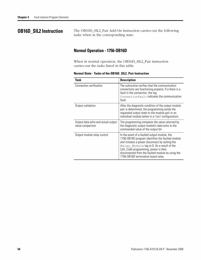
OB16D_SIL2 Instruction The OB16D_SIL2_Pair Add-On Instruction carries-out the following tasks when in the corresponding state.
Normal Operation - 1756-OB16D
When in normal operation, the OB16D_SIL2_Pair instruction carries-out the tasks listed in this table.
Normal State - Tasks of the OB16D_SIL2_Pair Instruction
Task Description
Connection verification The subroutine verifies that the communication connections are functioning properly. If a there is a fault in the connection, the tag ConnectionFault indicates the communication fault.
Output validation After the diagnostic condition of the output module pair is determined, the programming sends the requested output state to the module pair or an individual module (when in a 1oo1 configuration).
Output data echo and actual output value comparison
The programming compares the value returned by the diagnostic output module’s data echo to the commanded value of the output bit.
Output module relay control In the event of a faulted output module, the 1756-OB16D program identifies the faulted module and initiates a power disconnect by setting the Relay_Module tag to 0. As a result of the Call_Code programming, power is then disconnected from the faulted module by using the 1756-OB16D termination board relay.
54 Publication 1756-AT012A-EN-P - November 2008

Fault-tolerant Program Elements Chapter 3
1oo1 - 1756-OB16D
When the module pair is running in a 1oo1 configuration, one of the modules in the pair has been shut-down and the system is running on information from only the remaining (unfaulted) module. When the 1756-OB16D module pair is running in a 1oo1 configuration, the tasks listed in this table are carried-out.
When operating in a 1oo1 state, the pulse test frequency does not increase in the same manner that transition and reference tests do for the input modules. The pulse test continues to be carried-out at the frequency specified in the tag PulseTest_Interval_PerChnl.
The Fault-tolerant Program Once you understand the elements of the fault-tolerant program and how they function together, you are ready to configure and program your main routine.
Use Chapter 4, Configuring the Fault-tolerant System, and Chapter 5, Programming the Fault-tolerant System, as references when configuring and programming your fault-tolerant system.
1oo1 State - Tasks of OB16D_SIL2_Pair
Task Description
Countdown clock When the system begins operating in the 1oo1 state, the program starts a timer that when expired, annunciates that the user-defined repair time has elapsed. The repair time is specified in tag TimeToRun_1oo1.
The system will continue to run in a 1oo1 configuration after the repair time has elapsed.
The value in the tag FaultReset can be toggled to restart the timer.
Module status When the system is operating in a 1oo1 configuration, the OB16D_SIL2_Pair instruction provides module status information that is useful for troubleshooting the faulted module.
Publication 1756-AT012A-EN-P - November 2008 55

Chapter 3 Fault-tolerant Program Elements
Additional Resources
You can view or download Rockwell Automation publications at http://literature.rockwellautomation.com. To order paper copies of technical documentation, contact your local Rockwell Automation distributor or sales representative.
Resource Description
Logix5000 Common Programming Procedures Programming Manual, publication 1756-PM001
The programming manual describes common techniques and methods for using RSLogix 5000 software to program Logix5000 controllers.
Logix5000 Controllers Add-On Instructions, publication 1756-PM010
This manual describes features of Add-On Instructions and how to use them.
ControlLogix Controllers User Manual, publication 1756-UM001
This manual explains the general use of ControlLogix controllers.
ControlLogix Redundancy System User Manual, publication 1756-UM523
This user manual explains how to design, install, configure, and troubleshoot a redundant ControlLogix system.
Using ControlLogix in SIL2 Applications Safety Reference Manual, publication 1756-RM001
This safety reference manual provides information regarding ControlLogix components for use in SIL2 applications. Topics include hardware, software, and programming components.
56 Publication 1756-AT012A-EN-P - November 2008

Chapter 4
Configuring the Fault-tolerant System
About This Chapter This chapter describes procedures for configuring your fault-tolerant system.
Before You Begin Before you begin configuring your system, complete these tasks.
• Obtain Fault-tolerant SIL2 Add-On Instructions, see page 57
• Configure Your Redundant Controller Chassis, see page 58
Obtain Fault-tolerant SIL2 Add-On Instructions
Before configuring your system, obtain the fault-tolerant SIL2 Add-On Instructions from Rockwell Automation.
Topic Page
Before You Begin 57
Add the Remote I/O Chassis to the I/O Configuration Tree 58
About Module-defined Tags 64
Adding Required Controller Tags 65
Import Add-On Instructions 67
Using Add-On Instructions 68
1756-OB16D Module Pair Instruction Configuration 68
1756-IB32 Module Pair Instruction Configuration 76
1756-IF16 Module Pair Instruction Configuration 82
Next Steps 89
Additional Resources 89
Publication 1756-AT012A-EN-P - November 2008 57

Chapter 4 Configuring the Fault-tolerant System
Configure Your Redundant Controller Chassis
Before you begin configuring your fault-tolerant system, configure your redundant controller chassis and ControlNet network. For more information about how to prepare you redundant controller chassis, see the ControlLogix Redundancy System User Manual, publication 1756-UM523.
Configuring Remote I/O Chassis
To configure the remote-I/O chassis in RSLogix 5000 software, you must add the remote-I/O chassis and their modules to the I/O configuration tree.
Add the Remote I/O Chassis to the I/O Configuration Tree
To add your chassis and remote-I/O to the configuration tree, complete these steps.
1. Add two CNB or CNBR modules to the network and specify the Comm Format as None.
Specify the other module properties according to your system configuration.
TIP We recommend that you configure and program your fault-tolerant system offline.
After you have completed and verified your program, use RSNetWorx for ControlNet software to configure your redundant ControlNet network.
When your ControlNet network is configured, download the program and go online with the controller.
58 Publication 1756-AT012A-EN-P - November 2008

Configuring the Fault-tolerant System Chapter 4
2. Add and configure I/O modules so the configuration of each chassis and module pair is identical.
TIP In order to create identical duplicate chassis, you may find it easier to create the first chassis (in this example Chassis A) and then copy and paste it into the second chassis (in this example. Chassis B).
If you use this method of creating your duplicate chassis, verify that you have edited the parameters of the pasted configuration so that they are specific to that chassis.
TIP When configuring your I/O modules, use naming conventions that will allow you to easily identify the chassis pair, individual chassis, and module location.
For example, the I/O configuration examples in this manual use the following naming convention.
Creating tags with easy-to-understand identifiers helps when programming and troubleshooting the system.
IMPORTANT The order of the modules in the configuration tree and the module properties of both modules in the pair must be identical.
IMPORTANT Specify the module properties described on pages 60…62 when adding and configuring I/O modules.
Pr1_ChA_Slot1Chassis Pair Chassis Module Location
Publication 1756-AT012A-EN-P - November 2008 59

Chapter 4 Configuring the Fault-tolerant System
1756-IB32 Module Properties
Property ValueComm Format Input Data
Input Filter Time Must be identical between the two modules of the pair
60 Publication 1756-AT012A-EN-P - November 2008

Configuring the Fault-tolerant System Chapter 4
1756-IF16 Module Properties
IMPORTANT Verify that you specify Float Data - Single-Ended Mode - No Alarm as the Comm Format.
Property Value
Comm Format Float Data -Single-Ended Mode -No Alarm
Input Range 0 V...5 V for each channel (scaling is permitted)
IMPORTANT If you edit the 1756-IF16 module configuration any time after your initial start up, you must press fault reset in order to implement the new configuration parameters.
Publication 1756-AT012A-EN-P - November 2008 61

Chapter 4 Configuring the Fault-tolerant System
1756-OB16D Module Properties
Property Value
Comm Format Full Diagnostics - Output Data
Enable Diag. Latching Do not enable (uncheck boxes)
62 Publication 1756-AT012A-EN-P - November 2008

Configuring the Fault-tolerant System Chapter 4
3. If using an input module for fault and circuit resets, add a standard input module to the I/O Configuration tree.
In this example, a standard input module that is not part of a module pair is added in one of the remote-I/O chassis. Depending on your system, you may also choose to place the input module in a chassis separate from the fault-tolerant I/O or use an HMI input rather than the standard module input.
Once your chassis have been configured, your I/O configuration tree should be similar to the one below.
Publication 1756-AT012A-EN-P - November 2008 63

Chapter 4 Configuring the Fault-tolerant System
About Module-defined Tags
For each module you configure, the system generates tags for the module are created. These tags are referred to as module-defined or system-generated tags.
To view these tags, open the Controller Tags folder.
Module-defined Tags Resulting From I/O Configuration
The data in these tags is sensor data from the I/O modules and is used by the SIL2 Add-On Instructions (as specified for the parameters of the instruction) to compare point and channel values. The data from the I/O modules is also used when the instructions complete diagnostic tests and checks.
64 Publication 1756-AT012A-EN-P - November 2008

Configuring the Fault-tolerant System Chapter 4
Adding Required Controller Tags
Both the 1756-OB16D and the 1756-IF16 module pairs require the use of controller tags that are not contained in the Add-On Instructions.
About Controller Tags for the 1756-OB16D Module Pair
The OB16D SIL2 Add-On Instruction uses MSG instructions to initiate the pulse tests for the module pair. The MSG instructions require the use of MESSAGE tags and a SINT array tag for the source element.
You must add a MESSAGE tag for each 1756-OB16D module of each module pair in your system. For example, if you have three 1756-OB16D module pairs in your system, you need six tags of the MESSAGE type.
You must also add 1 SINT array of 10 elements for each 1756-OB16D module pair in your system. For example, if you have three 1756-OB16D module pairs in your system, you need three SINT[10] tags.
In summary, for each 1756-OB16D module pair, create these tags:
• 2 MESSAGE tags
• 1 SINT[10] tag
About Controller Tags for the 1756-IF16 Module Pair
If you are using a 1756-IF16 module pair, an array of 16 REAL elements is required. The IF16_SIL2_Pair instruction stores data for the 16 channels of the module pair to this array.
In summary, for each 1756-IF16 module pair, create this tag:
• 1 REAL[16]
Publication 1756-AT012A-EN-P - November 2008 65

Chapter 4 Configuring the Fault-tolerant System
Add Controller Tags
Add the required tags specific to your system in the Edit Tags tab of the Controller Tags folder.
66 Publication 1756-AT012A-EN-P - November 2008

Configuring the Fault-tolerant System Chapter 4
Import Add-On Instructions Complete these steps to import the fault-tolerant Add-On Instructions into your project.
1. Right-click the Add-On Instructions folder and select Import Add-On Instruction.
2. Select the Add-On Instruction file and click Import.
3. Repeat steps 1 and 2 for each fault-tolerant Add-On Instruction.
Note that the IF16_. instruction is imported as part of the IF16_SIL2_Pair instruction.
The Add-On Instruction folder now contains all three fault-tolerant Add-On Instructions.
Also, when you open the Main Routine, the fault-tolerant Add-On Instructions are now in the Add-On tab of the instruction toolbar.
Publication 1756-AT012A-EN-P - November 2008 67

Chapter 4 Configuring the Fault-tolerant System
Using Add-On Instructions To use the fault-tolerant Add-On Instructions, you should complete these tasks for each module pair in your system.
• Add the Add-On Instruction to your program and edit the instruction parameters for your module pair.
• Edit the tags contained within the instruction to specify diagnostic behaviors specific to your application.
1756-OB16D Module Pair Instruction Configuration
Any fault-tolerant SIL2 system requires the use of an 1756-OB16D module pair. The 1756-OB16D module pair controls the transition and reference tests of the input module pairs used in the system. To fully-configure your 1756-OB16D module pair, complete the tasks listed in this table.
IMPORTANT The SIL2 Add-On Instructions should be added to the Main Routine or another program that is fully-executed within the required safety-response time of your system.
TIP If you add and configure the Add-On Instruction for the 1756-OB16D module pair first (that is, before you add the Add-On Instructions for the input module pairs), the process for configuring the input Add-On Instruction parameters is easier.
This is because the Add-On Instructions for the input module pairs require the use of a parameter from the configured 1756-OB16D module pair Add-On Instruction.
Tasks Required for OB16D SIL2 Instruction Configuration
Task Page
Add the OB16D SIL2 Instruction and Edit Parameters 69
Edit OB16D SIL2 Add-On Instruction Tags 73
68 Publication 1756-AT012A-EN-P - November 2008

Configuring the Fault-tolerant System Chapter 4
Add the OB16D SIL2 Instruction and Edit Parameters
Complete these steps to add and configure an Add-On Instruction for a 1756-OB16D module pair.
1. Drag and drop the Add-On Instruction into the program.
2. Right-click the first operand and select New Tag.
3. Type a tag name and click OK.
Publication 1756-AT012A-EN-P - November 2008 69

Chapter 4 Configuring the Fault-tolerant System
4. For the ModuleX_Input and ModuleX_Output parameters, specify the input and output data for modules A and B of the module pair.
5. For the PTmsg_ModuleX parameters, specify the MESSAGE tags you created for each module of the pair.
6. Use the Message configuration dialog box to specify the Message instruction parameters for each PTmsg_ModuleX parameter.
a. To open the Message Configuration dialog box, click the … button.
Input data from each module of the pair.
Output data from each module of the pair.
Specify the module-defined tags specific to each module of the pair.
Message tag for module A of the pair.
Message tag for module B of the pair.
70 Publication 1756-AT012A-EN-P - November 2008

Configuring the Fault-tolerant System Chapter 4
b. Specify the Message Type, Service Type, and Source Element as shown.
c. Click the Communication tab.
Message Configuration Properties
For this property Specify this value
Message Type CIP Generic
Service Type Pulse Test
Source Element The name of the SINT[10] tag you created for the 1756-OB16D module pair.
Destination Do not specify a tag.
Publication 1756-AT012A-EN-P - November 2008 71

Chapter 4 Configuring the Fault-tolerant System
d. Browse to the 1756-OB16D module and click OK.
e. Click OK and OK again.
Your Message configuration is complete.
7. For the PulseTest_Settings parameter, specify the pulse test settings SINT[10] you created for the module.
8. For the reset parameters, specify the input points connected to the fault and circuit resets.
9. For the Output_Ctrl_RelayX parameters, specify the standard outputs you have assigned to control the termination board relay for that module of the pair.
72 Publication 1756-AT012A-EN-P - November 2008

Configuring the Fault-tolerant System Chapter 4
The completed OB16D SIL2 Add-On Instruction appears as shown here.
Edit OB16D SIL2 Add-On Instruction Tags
Editing the tags within the OB16D SIL2 Add-On Instruction specifies the behavior of the diagnostic tasks carried-out on the 1756-OB16D module pair.
We provide default tag values with the instruction, however, it is likely that you will need to edit some values to suit your system. For some tags in the instruction, specific values are required and the default values we provide should not be altered. For other tags, we recommend values, but you can choose to use different values based upon your system and safety application requirements.
Complete these steps to edit the tags provided in the OB16D SIL2 Add-On Instruction.
1. Double-click the … button to open the instruction properties.
Publication 1756-AT012A-EN-P - November 2008 73

Chapter 4 Configuring the Fault-tolerant System
The instruction’s properties dialog box displays.
2. Reference these tables and edit the recommended tag values to suit your application.
IMPORTANT Do not alter the default values of tags listed in the OB16D SIL2 Add-On Instruction Required Tag Values table. The default values must be used and are listed here only for your reference.
OB16D SIL2 Add-On Instruction Required Tag Values
Tag Name Description Value
Safety_Outputs_Select For fault-tolerant I/O, all 1756-OB16D module pair outputs are designated as safety outputs.
-1 at Safety_Outputs_Select
1 at each point, used or unused
PulseTest_Width Sets the maximum pulse test width and is specified in 100 μs increments.
20 (2 ms)
PulseTest_FaultDelay Sets the amount of time, in 100 μs increments, for the delay between the end of the pulse test and the declaration of a fault.
20 (2 ms)
74 Publication 1756-AT012A-EN-P - November 2008

Configuring the Fault-tolerant System Chapter 4
3. Click OK to apply changes and exit the instruction’s properties dialog box.
You have completed adding, configuring, and editing tags for one 1756-OB16D module pair. If you are using more than one 1756-OB16D module pair, complete all of these tasks for each remaining module pair.
OB16D SIL2 Add-On Instruction Recommended Tag Values
Tag Name Description Value
PulseTest_Chnl_Select Use to enable or disable the execution of pulse tests on points of the output module pair.(1)
1 = Pulse test enabled0 = Pulse test disabled
PulseTest_Interval_PerChnl Time, in ms, between pulse tests on individual output points.
The total time it takes for pulse tests to be carried-out on all points of the module pair is this value multiplied the number of outputs. This is true even when pulse tests are disabled for any of the points.
For example, when the 5 s is the PulseTest_Interval_PerChnl value, the total time required for all of the outputs to be pulse tested is 80 seconds (that is, 16 points x 5 s = 80 s).
5000 (5 s)
TimeToRun_1oo1 Preset value for the 1oo1 countdown timer, in ms.
28800000 (8 hour)
(1) Pulse tests must be disabled for outputs used to trigger diagnostic tests (that is, transition or reference tests) on input module pairs and outputs used to control relays on output termination boards.
Publication 1756-AT012A-EN-P - November 2008 75

Chapter 4 Configuring the Fault-tolerant System
1756-IB32 Module Pair Instruction Configuration
If you are using a 1756-IB32 module pair in your system, complete the tasks listed in this table to configure the IB32 SIL2 Add-On Instruction.
Add the IB32 SIL2 Instruction and Edit Parameters
1. Drag and drop the Add-On Instruction into the program.
2. Right-click the first operand and select New Tag.
Tasks Required for IF16 SIL2 Instruction Configuration
Task Page
Add the IB32 SIL2 Instruction and Edit Parameters 76
Edit IB32 SIL2 Add-On Instruction Tags 79
76 Publication 1756-AT012A-EN-P - November 2008

Configuring the Fault-tolerant System Chapter 4
3. Type a tag name and click OK.
4. For the ModuleX_Input parameters, specify the input data for modules A and B of the module pair.
5. For the reset parameters, specify the input points connected to the fault and circuit resets.
Input data from each module of the pair.
Specify the module-defined tags specific to each module of the pair.
Publication 1756-AT012A-EN-P - November 2008 77

Chapter 4 Configuring the Fault-tolerant System
6. For the Output_Ctrl_TransitionTestRelay, specify the output from the OB16D SIL2 Add-On Instruction that initiates 1756-IB32 module pair transition test.
The completed IB32 SIL Add-On Instruction appears as shown here.
78 Publication 1756-AT012A-EN-P - November 2008

Configuring the Fault-tolerant System Chapter 4
Edit IB32 SIL2 Add-On Instruction Tags
Editing the tags within the IB32 SIL2 Add-On Instruction specifies the behavior of the diagnostic tasks carried-out on the 1756-IB32 module pair.
We provide default tag values with the instruction, however, it is likely that you will need to edit some values to suit your system. For some tags in the instruction, specific values are required and the default values we provide should not be altered. For other tags, we recommend values, but you can choose to use different values based upon your system and safety application requirements.
Complete these steps to edit the tags provided in the IB32 SIL2 Add-On Instruction.
1. Double-click the … button to open the instruction properties.
The instruction’s properties dialog box displays.
Publication 1756-AT012A-EN-P - November 2008 79

Chapter 4 Configuring the Fault-tolerant System
2. Reference these tables and edit the recommended tag values to suit your application.
IB32 SIL2 Add-On Instruction Required Tag Values
Tag Name Description Value
Safety_Inputs_Select Any 1756-IB32 module pair inputs used in the fault-tolerant system are designated as safety inputs.
1 at each point used0 at unused points(1)
(1) Points of the 1756-IB32 module pair not used in the fault-tolerant system and not specified as safety inputs cannot be used for any other purpose.
IB32 SIL2 Add-On Instruction Recommended Tag Values
Tag Name Description Value
Miscompare_Test_Limit The number of subsequent program scans where a miscompare between points may occur before a fault is registered.
The value of four is strongly recommended in order to avoid nuisance trips as well as to provide a timely safety response.
If you choose to specify a value lower than four, your system may experience nuisance trips. However, you may choose to lower the value in order to decrease amount of time between a fault and the system response.
Depending upon the execution speed of your faul-tolerant program, you may choose to set a value higher than 4. However, setting a value higher than four increases the amount of time between the occurence of a miscompare and the system’s recognition and response to that miscompare.
4
ModulePair_GoodTestInterval Time, in ms, between transition tests when no module faults are present.
86400000 (24 hours)
ModulePair_1oo1TestInterval Time, in ms, between transition tests when the system is running in a 1oo1 configuration.
3600000 (1 hour)
80 Publication 1756-AT012A-EN-P - November 2008

Configuring the Fault-tolerant System Chapter 4
3. Click OK to apply changes and exit the instruction’s properties dialog box.
You have completed adding, configuring, and editing tags for one 1756-IB32 module pair. If you are using more than one 1756-IB32 module pair, complete all of these tasks for each of the remaining module pairs.
TimetoRun_1oo1 Preset value for 1oo1 countdown timer, in ms.
28800000 (8 hours)
TransitionTest_Low_Delay(1) Amount of time, in ms, delayed to allow the inputs to transition from high to low before checking the results of the transition test.
The amount of time to delay should be determined by adding your program scan time to the RPI. For example, if your total program scan time is 80 ms and your RPI is 20 ms, you should set your TransitionTest_Low_Delay value to 100 ms.
100
TransitionTest_High_Delay(1) Amount of time, in ms, delayed to allow inputs to transition to high before normal operation is resumed after a transition test.
The amount of time to delay should be determined by adding your program scan time to the RPI. For example, if your total program scan time is 80 ms and your RPI is 20 ms, you should set your TransitionTest_Low_Delay value to 100 ms.
100
(1) When specifying your TransitionTest_Low_Delay and TransitionTest_High_Delay values, remember that the system is functioning on the last-known verified data during these periods. If an input connected to the module pair changes (for example, if an E-stop is pressed), it will not be processed until the total time of these two values has expired and the systemstops using the last-known verified data.
IB32 SIL2 Add-On Instruction Recommended Tag Values
Tag Name Description Value
Publication 1756-AT012A-EN-P - November 2008 81

Chapter 4 Configuring the Fault-tolerant System
1756-IF16 Module Pair Instruction Configuration
If you are using a 1756-IF16 module pair in your system, complete the tasks listed in this table to configure the IB32 SIL2 Add-On Instruction.
Add-On Instruction for the 1756-IF16 Module Pair
Complete these steps to add and configure an Add-On Instruction for a 1756-IF16 module pair.
1. Drag and drop the IF16_SIL2 Pair Add-On Instruction into the program.
Tasks Required for IF16 SIL2 Instruction Configuration
Task Page
Add-On Instruction for the 1756-IF16 Module Pair 82
Edit IF16 SIL2 Add-On Instruction Tags 85
82 Publication 1756-AT012A-EN-P - November 2008

Configuring the Fault-tolerant System Chapter 4
2. Right-click the first operand and select New Tag.
3. Type a tag name and click OK.
4. For the ModuleX_Input and ModuleX_ConfigData parameters, specify the input and configuration data for modules A and B of the module pair.
Input and configuration data from module A of the pair.
Specify the module-defined tags specific to module A of the pair.
Input and configuration data from module B of the pair.
Specify the module-defined tags specific to module B of the pair.
Publication 1756-AT012A-EN-P - November 2008 83

Chapter 4 Configuring the Fault-tolerant System
5. For the reset parameters, specify the input points connected to the fault and circuit resets.
6. For the Output_Ctrl_ReferenceTestRelay, specify the output from the OB16D SIL2 Add-On Instruction that initiates 1756-IF16 module pair reference test.
7. For the Data parameter, specify the tag of real data that you created for the 1756-IF16 module pair.
The completed IF16 SIL Add-On Instruction appears as shown here.
84 Publication 1756-AT012A-EN-P - November 2008

Configuring the Fault-tolerant System Chapter 4
Edit IF16 SIL2 Add-On Instruction Tags
Editing the tags within the IF16 SIL2 Add-On Instruction specifies the behavior of the diagnostic tasks carried-out on the 1756-IF16 module pair.
We provide default tag values with the instruction, however, it is likely that you will need to edit some values to suit your system. For some tags in the instruction, specific values are required and the default values we provide should not be altered. For other tags, we recommend values, but you can choose to use different values based upon your system and safety application requirements.
Complete these steps to edit the tags provided in the IF16 SIL2 Add-On Instruction.
1. Double-click the … button to open the instruction properties.
The instruction’s properties dialog box displays.
Publication 1756-AT012A-EN-P - November 2008 85

Chapter 4 Configuring the Fault-tolerant System
2. Reference these tables and edit the recommended tag values to suit your application.
IMPORTANT You must edit the Safety_Inputs_Select tag specific to your safety application requirements.
You are not required to edit the recommended tag values for the other (recommended) tags listed unless your application requires the changes.
IF16 SIL2 Add-On Instruction Required Tag Values
Tag Name Description Value
Safety_Inputs_SelectEnter 1 for any analog input channel being used.(1)
(1) Unused safety input channels cannot be used for any other purposes (that is, they cannot be used as nonfault-tolerant I/O channels). We recommend that you configure unused channels for voltages of 0…5V and then jumper or ground unused channels to keep channel values within range.
1 in each channel used0 in each unused channel
IF16 SIL2 Add-On Instruction Recommended Tag Values
Tag Name Description Value
Miscompare_Test_Limit The number of subsequent program scans where a miscompare between points may occur before a fault is registered.
The value of four is strongly recommended in order to avoid nuisance trips as well as provide a timely safety response.
If you choose to specify a value lower than four, your system may experience nuisance trips. However, you may choose to lower the value in order to decrease amount of time between a fault and the system response.
Setting a value larger then four is not recommended as the response to a fault may be too long for most safety applications.
4
ModulePair_Good_TestInterval Time, in ms, between transition tests when no module faults are present.
86400000 (24 hours)
ModulePair_1oo1Test_Interval Time, in ms, between transition tests when the system is running in a 1oo1 configuration.
3600000 (1 hour)
TimetoRun_1oo1 Preset value for 1oo1 countdown timer, in ms.
28800000(8 hours)
86 Publication 1756-AT012A-EN-P - November 2008

Configuring the Fault-tolerant System Chapter 4
SwitchToRefValue_Delay(1) Amount of time, in ms, delayed to allow the inputs to transition to the reference values before checking the results of the reference test.
This value should be equal or greater than your analog module pair’s RTS rate.
500
SwitchToSignal_Delay(1) Amount of time, in ms, delayed to allow the inputs to transition to the field signal values before normal operation is resumed.
This value should be equal or greater than your analog module pair’s RTS rate.
500
ReferenceTest_Deadband_ChX(2) Defines the ± deadband when, during a reference test, the channel value is compared to the reference voltages.
The value is entered as a percentage of the engineering or scaled units.
For example, in an application where:
• High Voltage = 5 V• Low Voltage = 0 V• High Engineering = 200• Low Engineering = 0
Defining a channel comparison deadband of 0.05 results in a the channel comparison being considered a match if the values are within 10 units of each other.
0.05 (at each channel), that is 5%
ChnlCompare_Deadband_ChX(2) Defines the ± deadband when the same two channels of the pair are compared during normal operation.
The value is entered as a percentage of the engineering or scaled units.
For example, in an application where:
• High Voltage = 5 V• Low Voltage = 0 V• High Engineering = 200• Low Engineering = 0
Defining a channel comparison deadband of 0.05 results in the channel comparison being considered a match if the values are within 10 units of each other.
0.05 (at each channel), that is 5%
IF16 SIL2 Add-On Instruction Recommended Tag Values
Tag Name Description Value
Publication 1756-AT012A-EN-P - November 2008 87

Chapter 4 Configuring the Fault-tolerant System
3. Click OK to apply changes and exit the instruction’s properties dialog box.
You have completed adding, configuring, and editing tags for one 1756-IF16 module pair. If you are using more than one 1756-IF16 module pair, complete all of these tasks for each remaining module pair.
ChnlValues_at_Fault_ChX Sets the channel values that are used by fault-tolerant system in the event of both modules of the pair faulting. These values should be entered in engineering units.
0.0
(1) When specifying your SwitchToRef_Delay and SwitchToSignal_Delay values, remember that the system is functioning on the last-known verified data during these periods. If an input connected to the module pair changes, it will not be processed until the total time of these two values has expired and the system has stopped using the last-known verified data.
(2) If changes are made to the ChnlCompare_Deadband or to the ReferenceTest_Deadband tag values after the initial fault-tolerant program is downloaded to and running on the controller, then you must press fault-reset so that the IF16_RefCal subroutine is carried out and the new deadband values are implemented. The changes to these tags are not implemented into the program until the IF16_RefCal subroutine is run.
IF16 SIL2 Add-On Instruction Recommended Tag Values
Tag Name Description Value
88 Publication 1756-AT012A-EN-P - November 2008

Configuring the Fault-tolerant System Chapter 4
Next Steps After you have completed the configurations, specifications, and edits described in this chapter, your next step is to program the SIL2 system Main Routine.
See Programming the Fault-tolerant System on page 91 for more information about programming the main routine.
Additional Resources
You can view or download Rockwell Automation publications at http://literature.rockwellautomation.com. To order paper copies of technical documentation, contact your local Rockwell Automation distributor or sales representative.
Resource Description
Logix5000 Common Programming Procedures Programming Manual, publication 1756-PM001
The programming manual describes common techniques and methods for using RSLogix 5000 software to program Logix5000 controllers.
Logix5000 Controllers Add-On Instructions, publication 1756-PM010
This manual describes features of Add-On Instructions and how to use them.
ControlLogix Controllers User Manual, publication 1756-UM001
This manual explains the general use of ControlLogix controllers.
ControlLogix Redundancy System User Manual, publication 1756-UM523
This user manual explains how to design, install, configure, and troubleshoot a redundant ControlLogix system.
Using ControlLogix in SIL2 Applications Safety Reference Manual, publication 1756-RM001
This safety reference manual provides information regarding ControlLogix components for use in SIL2 applications. Topics include hardware, software, and programming components.
ControlLogix Digital I/O Modules User Manual, publication 1756-UM058
Provides information about digital I/O modules including: features, configuration, and troubleshooting.
Publication 1756-AT012A-EN-P - November 2008 89

Chapter 4 Configuring the Fault-tolerant System
90 Publication 1756-AT012A-EN-P - November 2008
Chapter 5
Programming the Fault-tolerant System
About This Chapter This chapter describes suggested methods for programming the fault-tolerant system.
Programming the Main Routine
After you have added and configured your SIL2 Add-On Instructions, you can write the program to control the system in the Main Routine.
This section provides some guidelines and tips for programming the system. It describes some of the many methods you might use to initiate a shutdown of the system in the event of a module pair fault. Also described are some programming methods that might be used to control the response to a demand on the safety system.
These are only guidelines and suggestions as you are responsible for programming the SIL2 system according to your application requirements.
Topic Page
Programming the Main Routine 91
Basic Input/Output Programming 92
Example Input/Output Rung 92
Module Pair Fault to Result in System Shutdown 92
Demand Made Through a 1756-IB32 Module Pair 93
Demand Made Through a 1756-IF16 Module Pair 94
Power-up Sequence 95
Additional Resources 96
Publication 1756-AT012A-EN-P - November 2008 91

Chapter 5 Programming the Fault-tolerant System
Basic Input/Output Programming
Basic input to output programming for I/O modules in the fault-tolerant system varies very little from programming for a nonfault-tolerant system. The only difference is in the use of module pair tags that appear slightly different than typical system generated tags.
Example Input/Output Rung
This is an example of the basic input/output rung in a fault-tolerant program.
Example of Input/Output Rung
Module Pair Fault to Result in System Shutdown
Some fault-tolerant applications may require that the system shutdown in the event of a fault at any module pair.
For example, in your application, if both modules of the 1756-IB32 module pair is faulted, the resulting safe state for the system may be a total system shutdown.
If your application requires a shutdown when both modules of a module pair are faulted, use programming similar to that shown here.
Reconciled input point data from modules A and B of the module pair (produced by the IB32_SIL2_Pair instruction).
Data to corresponding points on the output module pair (goes to OB16D_SIL2_Pair instruction).
92 Publication 1756-AT012A-EN-P - November 2008
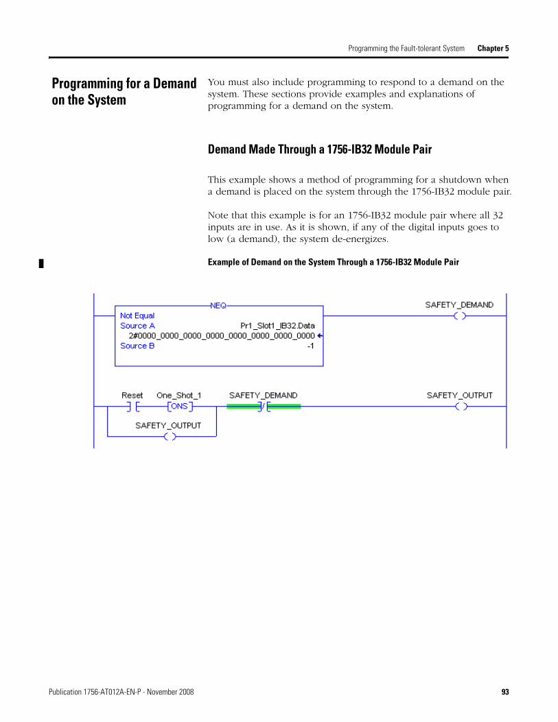
Programming the Fault-tolerant System Chapter 5
Programming for a Demand on the System
You must also include programming to respond to a demand on the system. These sections provide examples and explanations of programming for a demand on the system.
Demand Made Through a 1756-IB32 Module Pair
This example shows a method of programming for a shutdown when a demand is placed on the system through the 1756-IB32 module pair.
Note that this example is for an 1756-IB32 module pair where all 32 inputs are in use. As it is shown, if any of the digital inputs goes to low (a demand), the system de-energizes.
Example of Demand on the System Through a 1756-IB32 Module Pair
Publication 1756-AT012A-EN-P - November 2008 93

Chapter 5 Programming the Fault-tolerant System
Demand Made Through a 1756-IF16 Module Pair
These examples show methods of programming for a shutdown when a demand is placed on the system through one channel of the 1756-IF16 module pair.
Depending on your application, your programming may use different, but similar, programming than that shown here.
Example of Demand Through a 1756-IF16 Module Pair
94 Publication 1756-AT012A-EN-P - November 2008

Programming the Fault-tolerant System Chapter 5
Power-up Sequence Once you have completed your system programming, you should configure your ControlNet network and download the project to the controller.
After you put the controller into Run mode or you turn on a controller with a fault-tolerant program loaded, there is a sequence of power up steps that you must carry-out. These steps are explained below.
1. Wait five seconds to allow I/O data to be read and established.
2. Press fault reset to clear the faults of the 1756-OB16D module pair.
This reset clears the module pair faults and applies power to the 1756-OB16D module pair outputs (via the 1756-OBxx modules).
3. Press circuit reset to set the 1756-OB16D module pair outputs to their commanded state.
4. Press fault reset to carry-out the reference calculations and to verify that all faults of the input modules have been cleared.
After completing these steps, your fault-tolerant system is online and fully operational.
IMPORTANT After you have applied power or put the controller into Run mode, the 1756-OB16D module pair faults. This behavior is programmed into the fault-tolerant system in order to protect personnel and machinery from sudden output.
Publication 1756-AT012A-EN-P - November 2008 95

Chapter 5 Programming the Fault-tolerant System
Additional Resources
You can view or download Rockwell Automation publications at http://literature.rockwellautomation.com. To order paper copies of technical documentation, contact your local Rockwell Automation distributor or sales representative.
Resource Description
Logix5000 Common Programming Procedures Programming Manual, publication 1756-PM001
The programming manual describes common techniques and methods for using RSLogix 5000 software to program Logix5000 controllers.
ControlLogix Controllers User Manual, publication 1756-UM001
This manual explains the general use of ControlLogix controllers.
ControlLogix Redundancy System User Manual, publication 1756-UM523
This user manual explains how to design, install, configure, and troubleshoot a redundant ControlLogix system.
Using ControlLogix in SIL2 Applications Safety Reference Manual, publication 1756-RM001
This safety reference manual provides information regarding ControlLogix components for use in SIL2 applications. Topics include hardware, software, and programming components.
96 Publication 1756-AT012A-EN-P - November 2008

Chapter 6
Troubleshooting a Fault-tolerant System
About This Chapter This chapter explains recommended procedures for troubleshooting a fault-tolerant system. It also contains examples of status information that may result when faults are present in the system.
Identifying a Faulted Module Pair
In order to identify a faulted module pair, you should examine these tags. Each of these tags is created when you use the SIL2 Add-On Instruction for any of the three module types.
Topic Page
Identifying a Faulted Module Pair 97
Identifying a Faulted Module 99
Example of Programming to Identify a Faulted Module Pair 98
Identifying a Faulted Module 99
Replacing a Faulted 1756-IB32 Module 98
1756-IB32 Module Pair Tags to Identify the Type of Module Fault 100
1756-IF16 Module Pair Tags to Identify the Type of Module Fault 100
1756-OB16D Module Pair Tags to Identify the Type of Module Fault 101
Using Resets 101
Examples of Faults and Resulting Tag Values 103
Tags Used to Identify a Faulted Module Pair
Tag Indicates
ModulePair_Good If both modules of the pair are functioning without faults.
1 = Both modules are functioning properly0 = A fault is present on one or both modules of the pair
ModulePair_1oo1 If the module pair is operating in a 1oo1 configuration (that is, only one module of the pair is functioning properly).
1 = Module pair is operating in a 1oo1 configuration0 = Both modules are either OK or faulted, and not 1oo1
ModulePair_Faulted If both the modules of the pair are faulted. Depending on your application, a status of 1 at this tag may initiate a shutdown.
1 = Both modules of the pair faulted0 = Module pair functioning properly or in a 1oo1 configuration.
Run_1oo1_Countdown The time remaining on the TimeToRun1oo1 timer if the module pair is operating in a 1oo1 configuration.
Publication 1756-AT012A-EN-P - November 2008 97

Chapter 6 Troubleshooting a Fault-tolerant System
Replacing a Faulted 1756-IB32 Module
If your 1756-IB32 module pair is operating 1oo1 at a point-level (that is one module of the pair has a faulted point and the other module is fully-functional), removing the swing-arm of the module with point-level faults causes your system to fail-to-safe due to a miscompare.
The miscompare occurs because data from the unfaulted points of the module continue to be used and checked by the Add-On Instruction programming. Removing the swing-arm causes the remaining unfaulted points to go low (0) and a miscompare of data occurs.
Example of Programming to Identify a Faulted Module Pair
When troubleshooting your fault-tolerant system after a fault on a module pair has occurred, you may choose to examine module status tags by going online with the controller or by programming an HMI or similar notification system to annunciate and identify the faulted module pair.
This example shows one method of programming so that the status of the module pair is displayed. Programming similar to that shown here may be used to demonstrate the status of the module pair on a Control Tower or similar device.
IMPORTANT To avoid a shutdown due to a miscompare, remove the entire 1756-IB32 module from the chassis before removing the swing-arm.
98 Publication 1756-AT012A-EN-P - November 2008

Troubleshooting a Fault-tolerant System Chapter 6
Example of Module Pair Status Programming
Identifying a Faulted Module
In order to identify a faulted module, you should examine these tags. Each of these tags is created when you create the module pair data type tags for any of the three module types.
Once you have used the tags listed above to identify a faulted module, there are additional tags you can view to determine what type of fault exists on the module.
Each module type uses different tags to identify the type of fault. Use the section specific to your module to determine which type of fault exists on the module.
Module Pair Tags Used to Identify a Faulted Module
Tag Indicates
Module_A_Faulted The fault status of module A.
1 = Module A faulted0 = Module A functioning properly
Module_B_Faulted The fault status of module B.
1 = Module B faulted0 = Module B functioning properly
Publication 1756-AT012A-EN-P - November 2008 99

Chapter 6 Troubleshooting a Fault-tolerant System
1756-IB32 Module Pair Tags to Identify the Type of Module Fault
The instruction for the 1756-IB32 modules uses tags that can help identify these types of faults:
• Connection and communication faults.
• Points on the module faulted (for example, a miscompare or stuck-at-one condition).
• Point or points fail to transition from one to zero during transition test (for example, due to an internal short).
These are the tags that contain the 1756-IB32 module status data and can be used to determine the type of module fault.
1756-IF16 Module Pair Tags to Identify the Type of Module Fault
The instruction for the 1756-IF16 modules uses tags that can help identify these types of faults:
• Connection and communication faults.
• Channels on the module faulted (for example, due to a miscompare or over/under range).
• Channels faulted as determined during the reference test.
These are the tags that contain the 1756-IF16 module status data and can be used to determine the type of module fault..
1756-IB32 Module Status Tags
Tag Indicates
ConnectionFault_Module_X Connection or communication faults
Chnl_OK_Module_X Point-level faults
ChnlFlt_StuckAtOne_Module_X Point-level faults.
Module_X_Faulted Module-level faults.
1756-IF16 Module Status Tags
Tag Indicates
ConnectionFault_Module_X Connection or communication faults
Chnl_OK_Module_X Channel-level faults
ChnlFlt_RefTest_Module_X Channel-level faults found during reference test
Chnl_Miscompare_Status Channel-level faults
Module_X_Faulted Module-level faults.
100 Publication 1756-AT012A-EN-P - November 2008

Troubleshooting a Fault-tolerant System Chapter 6
1756-OB16D Module Pair Tags to Identify the Type of Module Fault
The instruction for the 1756-OB16D module uses tags that can help identify these types of faults:
• Connection and communication faults.
• No load conditions (detects no load conditions only between the output module and termination board).
• Points stuck at low.
• Points stuck at high.
• Other hardware failures.
These are the tags that contain the 1756-OB16D module status data and can be used to determine the type of module fault.
Using Resets After you have finished troubleshooting and repairing a faulted module condition, you must reset the system so that the faults are cleared and the system operates by using data from the repaired module.
Depending on the type of fault and the configuration the system is running in, you may be required to reset both the fault status tags and the data tags (by using the circuit reset).
When to Use the Fault Reset
After you have repaired or replaced the faulted module, or corrected any other issues that might cause a module fault, you must use the Fault Reset button. Pressing the fault reset button results in all of the
1756-OB16D Module Status Tags
Tag Indicates
ConnectionFault_Module_X Connection or communication faults
Chnl_OK_Module_X Channel-level faults
ChnlFlt_PulseTest_Module_X Channel-level faults found during reference test
Chnl_Grounded_Module_X Channel that may be shorted-to-ground
ChnlHWFail_Module_X Module-level hardware failure
Chnl_Miscompare_Status Channel-level faults
Chnl_NoLoadOrDCV_Module_X Channel-level no load (wire off) or short to 24 V DC fault
Module_X_Faulted Module-level faults.
Publication 1756-AT012A-EN-P - November 2008 101

Chapter 6 Troubleshooting a Fault-tolerant System
module fault status tags being reset. However, module data tags are not reset.
If your system was operating in a 1oo1 configuration at the module fault, the fault reset is the only action you need to take in order to enable the system to use data from the newly-repaired module.
When to Use Circuit Reset
If both modules of the pair are faulted, you must use the circuit reset after using the fault reset.
Because the fault reset clears the module fault status tags only , the faulted values are still present in the module data tags. 1756-IB32 module data tags fault values are 0, and 1756-IF16 fault values are those specified in tags ChnlValues_at_Fault.
Using the circuit reset results in the faulted data values being cleared and the system begins to use the sensor data from the modules.
102 Publication 1756-AT012A-EN-P - November 2008

Troubleshooting a Fault-tolerant System Chapter 6
Examples of Faults and Resulting Tag Values
These examples show how the module pair tags appear before and after a certain module fault occurs. Each column of the tables indicates what action has taken place. The tags listed in the rows of the columns indicate the tag values after the action has occurred.
1756-IB32 Module Pair - One Module Faulted
In this example, module A of the 1756-IB32 module pair has a stuck-at-one condition caused by an internal short. The stuck-at-one condition is detected during the next transition test.
This table shows which tags values change from the time the transition test detects the fault to the point when the fault is cleared and the system is again using data from the repaired module.
Tag Values After a Stuck-At-One Condition Detected on a 1756-IB32 Module
Tag Values During Normal Operation (No Faults)
Values After Fault Detected
Values After Faults Repaired and Fault Reset
Values After Circuit Reset
ConnectionFault_Module_A 0 0 0 N/A(1)
ConnectionFault_Module_B 0 0 0 N/A(1)
Chnl_OK_Module_A 1 (at each point) 0 (at affected points) 1 (at each point) N/A(1)
Chnl_OK_Module_B 1 (at each point) 1 (at each point affected) 1 (at each point) N/A(1)
Chnl_Miscompare_Status 0 (at each point) 0 (at each point) 0 (at each point) N/A(1)
ChnlFlt_StuckAtOne_Module_A 0 1 (at each point affected) 0 N/A(1)
ChnlFlt_StuckAtOne_Module_B 0 0 0 N/A(1)
Data From modules A and B From module B From modules A and B N/A(1)
ModulePair_Good 1 0 1 N/A(1)
Module_Pair_1oo1 0 1 0 N/A(1)
ModulePair_Faulted 0 0 0 N/A(1)
Module_A_Faulted 0 1 0 N/A(1)
Module_B_Faulted 0 0 0 N/A(1)
Run_1oo1_Countdown Preset Counting down Preset N/A(1)
(1) Circuit reset is not needed in this case because the system did not stop using data from the module pair.
Publication 1756-AT012A-EN-P - November 2008 103

Chapter 6 Troubleshooting a Fault-tolerant System
1756-IF16 Module Pair - One Module Faulted and Removed
In this example, module B of the 1756-IF16 module pair has a fault caused by an internal short. The tag value changes are shown after the fault is identified by the reference test, when the module is removed for repair, and after the module has been replaced and the faults reset.
Tag Values After Faulted Channel Detected on a 1756-IF16 Module
Tags Values During Normal Operation (No Faults)
Values After Fault Detected
Values AfterModule B Removed
Values After Module B Replaced and Fault Reset
ConnectionFault_Module_A 0 0 0 0
ConnectionFault_Module_B 0 0 1 0
Chnl_OK_Module_A 1 (at each channel) 1 (at each channel) 1 (at each channel) 1 (at each channel)
Chnl_OK_Module_B 1 (at each channel) 0 (at affected channel) 0 (at each channel) 1 (at each channel)
ChnlFlt_RefTest_Module_A 0 0 (at each channel) 0 (at each channel) 0 (at each channel)
ChnlFlt_RefTest_Module_B 0 1 (at affected channels) 0 (at each channel) 0 (at each channel)
Chnl_Miscompare_Status 0 0 (at each channel) 0 (at each channel) 0 (at each channel)
Data From modules A and B From module A From module A From modules A and B
ModulePair_Good 1 0 0 1
Module_Pair_1oo1 0 1 1 0
ModulePair_Faulted 0 0 0 0
Module_A_Faulted 0 0 0 0
Module_B_Faulted 0 1 1 0
Run_1oo1_Countdown Preset Counting down Counting down Preset
104 Publication 1756-AT012A-EN-P - November 2008

Troubleshooting a Fault-tolerant System Chapter 6
1756-IF16 Module Pair - Two Modules Faulted
In this example, a fault occurs on module B of the module pair. Then, while operating 1oo1, module A faults as well. The table shows the progression of tag values through the initial fault on module B through the circuit reset.
Tag Values After 1756-IF16 Module Pair Faulted
Tags Values During Normal Operation (No Faults)
Values After Module B Fault Detected
Values After Module A Fault Detected
Values After Faults Corrected and Fault Reset
Values After Circuit Reset
ConnectionFault_Module_A 0 0 0 0 0
ConnectionFault_Module_B 0 0 0 0 0
Chnl_OK_Module_A 1 (at each channel) 1 (at each channel) 0 (at affected channels)
1 (at each channel) 1 (at each channel)
Chnl_OK_Module_B 1 (at each channel) 0 (at affected channels)
0 (at affected channels)
1 (at each channel) 1 (at each channel)
ChnlFlt_RefTest_Module_A 0 (at each channel) 0 (at each channel) 1 (at affected channels)
0 (at each channel) 0 (at each channel)
ChnlFlt_RefTest_Module_B 0 (at each channel) 1 (at affected channels)
1 (at affected channels)
0 (at each channel) 0 (at each channel)
Chnl_Miscompare_Status 0 (at each channel) 0 (at each channel) 0 (at each channel)
0 (at each channel) 0 (at each channel)
Data From modules A and B From module A As set for fault values
As set for fault values
From modules A and B
ModulePair_Good 1 0 0 1 1
Module_Pair_1oo1 0 1 0 0 0
ModulePair_Faulted 0 0 1 0 0
Module_A_Faulted 0 0 1 0 0
Module_B_Faulted 0 1 1 0 0
Run_1oo1_Countdown Preset Counting down Preset Preset Preset
Publication 1756-AT012A-EN-P - November 2008 105

Chapter 6 Troubleshooting a Fault-tolerant System
Additional Resources
You can view or download Rockwell Automation publications at http://literature.rockwellautomation.com. To order paper copies of technical documentation, contact your local Rockwell Automation distributor or sales representative.
Resource Description
ControlLogix Digital I/O Modules User Manual, publication 1756-UM058
Provides information about digital I/O modules including: features, configuration, and troubleshooting.
Logix5000 Common Programming Procedures Programming Manual, publication 1756-PM001
The programming manual describes common techniques and methods for using RSLogix 5000 software to program Logix5000 controllers.
ControlLogix Controllers User Manual, publication 1756-UM001
Explains the general use of ControlLogix controllers.
ControlLogix Redundancy System User Manual, publication 1756-UM523
Explains how to design, install, configure, and troubleshoot a redundant ControlLogix system.
Using ControlLogix in SIL2 Applications Safety Reference Manual, publication 1756-RM001
Provides information regarding ControlLogix components for use in SIL2 applications. Topics include hardware, software, and programming components.
106 Publication 1756-AT012A-EN-P - November 2008

Appendix A
SIL2 Add-On Instruction Tags
About This Appendix This appendix provides tag names, purposes, and values for each tag within the SIL2 Add-On Instructions. Use this appendix as a reference when programming your SIL2 fault-tolerant Add-On Instructions.
1756-IB32 Module Pair Tags The tags provided in the following tables are used to configure, specify, and monitor 1756-IB32, DC input module behavior in a ControlLogix fault-tolerant system.
IB32_SIL2_Pair Tags for System Behavior
You must enter values for each these module pair tags. For some tags, the value specified is required. For others, the values are recommended.
Topic Page
1756-IB32 Module Pair Tags 107
IB32_SIL2_Pair Tags for System Behavior 107
IB32_SIL2_Pair Module Status Tags 109
IB32_SIL2_Pair Tags for Use in Programming 111
IB32_SIL2_Pair Tags Not for Use 111
1756-IF16 Module Pair Tags 112
IF16_SIL2_Pair Tags for System Behavior 112
IF16_SIL2_Pair Module Status Tags 114
IF16_SIL2_Pair Tags for Use in Programming 116
IF16_SIL2_Pair Tags Not for Use 117
1756-OB16D Module Pair Tags 118
OB16D_SIL2_Pair Tags for System Behavior 118
OB16D_SIL2_Pair Module Status Tags 119
OB16D_SIL2_Pair Tags for Use in Programming 121
OB16D_SIL2_Pair Tags Not for Use 122
Publication 1756-AT012A-EN-P - November 2008 107

Appendix A SIL2 Add-On Instruction Tags
IB32_SIL2_Pair Tags Used to Specify System Behavior
Tag Name Description Value Required or Recommended
Safety_Input_Select Use to select or deselect the inputs that are used for safety functions.
1 (at each point used) Required
Miscompare_Test_Limit Defines the number of times a miscompare between points is permitted before a fault is declared.
4(1) Recommended
ModulePair_Good_TestInterval Time, in ms, between transition tests. The program uses this value when the module pair is without faults.
86400000 (24 hours) Recommended
ModulePair_1oo1_TestInterval Time, in ms, between transition tests if the module pair is operating in a 1oo1 configuration. The program uses this value when a fault is present on one module of the pair.
3600000 (1 hour) Recommended
TimeToRun_1oo1.PRE User-defined time, in ms, for the 1oo1 countdown timer that is the repair time.
28800000 (8 hours) Recommended
TransitionTest_Low_Delay.PRE Amount of time, in ms, delayed to allow the inputs to transition from high to low before checking the results of the transition test.
The amount of time to delay should be determined by adding your program scan time to the RPI. For example, if your total program scan time is 80 ms and your RPI is 20 ms, you should set your TransitionTest_Low_Delay value to 100 ms.
100(2) Recommended
TransitionTest_High_Delay.PRE Amount of time, in ms, delayed to allow inputs to transition to high before normal operation is resumed after a transition test.
The amount of time to delay should be determined by adding your program scan time to the RPI. For example, if your total program scan time is 80 ms and your RPI is 20 ms, you should set your TransitionTest_Low_Delay value to 100 ms.
100(2) Recommended
(1) The value of four is strongly recommended in order to avoid nuisance trips as well as to provide a timely safety response. If you choose to specify a value lower than four, your system may experience nuisance trips. However, you may choose to lower the value in order to decrease amount of time between a fault and the system response.
Depending upon the execution speed of your faul-tolerant program, you may choose to set a value higher than 4. However, setting a value higher than four increases the amount of time between the occurence of a miscompare and the system’s recognition of that miscompare.
(2) When specifying your TransitionTest_Low_Delay and TransitionTest_High_Delay values, remember that the system is functioning on the last-known verified data during these periods. If an input connected to the module pair changes (for example, if an E-stop is pressed), it will not be processed until the total time of these two values has expired and the system has stopped using the last-known verified data
108 Publication 1756-AT012A-EN-P - November 2008

SIL2 Add-On Instruction Tags Appendix A
IB32_SIL2_Pair Module Status Tags
The module status tags provide diagnostic information for the module pair. These tags are used in several ways in the fault-tolerant system. Uses include:
• in the main routine to determine system behavior.
• in the subroutine to determine and report module pair status.
• in conjunction with HMI and other indicators of system status.
1756-IB32 Module Status Tags
Tag Name Description
ConnectionFault_Module_A Indicates the status of the connection to module A.
1 = Connection lost 0 = Connection good
ConnectionFault_Module_B Indicates the status of the connection to module B.
1 = Connection lost 0 = Connection good
Chnl_OK_Module_A Bit-level indicators of what points are operating without fault on module A.
1 = Point is functional 0 = Point is faulted
Chnl_OK_Module_B Bit-level indicators of what points are operating without fault on module B.
1 = Point is functional0 = Point is faulted
ChnlFlt_StuckAtOne_Module_A Bit-level indicators of points on module A that are stuck at one after the transition test.
1 = Point is stuck at one0 = Point is functional
ChnlFlt_StuckAtOne_Module_B Bit-level indicators of points on module B that are stuck at one after the transition test.
1 = Point is stuck at one0 = Point is functional
Chnl_Miscompare_Status Bit-level indicators that show what points of the module pair do not match each other (miscompare).
1 = Point status between modules is different 0 = Point status is the same
ModulePair_Good Status bit that indicates that both modules of the module pair are functioning properly.
1 = Module pair functioning properly0 = Fault present (on one or both modules)
Publication 1756-AT012A-EN-P - November 2008 109
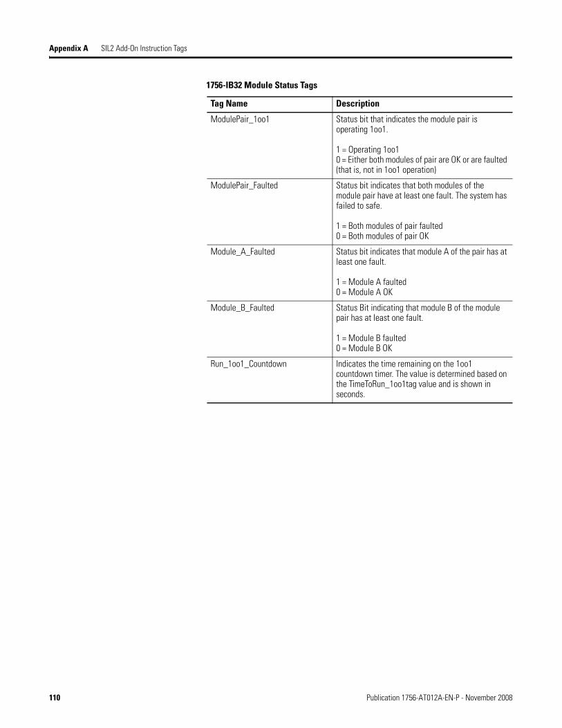
Appendix A SIL2 Add-On Instruction Tags
ModulePair_1oo1 Status bit that indicates the module pair is operating 1oo1.
1 = Operating 1oo10 = Either both modules of pair are OK or are faulted (that is, not in 1oo1 operation)
ModulePair_Faulted Status bit indicates that both modules of the module pair have at least one fault. The system has failed to safe.
1 = Both modules of pair faulted0 = Both modules of pair OK
Module_A_Faulted Status bit indicates that module A of the pair has at least one fault.
1 = Module A faulted 0 = Module A OK
Module_B_Faulted Status Bit indicating that module B of the module pair has at least one fault.
1 = Module B faulted 0 = Module B OK
Run_1oo1_Countdown Indicates the time remaining on the 1oo1 countdown timer. The value is determined based on the TimeToRun_1oo1tag value and is shown in seconds.
1756-IB32 Module Status Tags
Tag Name Description
110 Publication 1756-AT012A-EN-P - November 2008

SIL2 Add-On Instruction Tags Appendix A
IB32_SIL2_Pair Tags for Use in Programming
These tags are to be used in the Main Routine. Your program ahouls use the data in these tags to determine system behavior.
IB32_SIL2_Pair Tags Not for Use
There are tags within the SIL2 Add-On Instructions that cannot be altered.
• DataCompareCounter
• L_Scr_a
• QualityMask1
• QualityMask2
• OneShot_Bits
• TransitionTestInterval
• FaultResetTimer
• Fault
• Data
• Good2Go
IB32_SIL2_Pair Tags for Use in Programming
Tag Name Description
Data During normal operation these input bits are the reconciled values of two points on the module pair.
During 1oo1 operation, these input bits contain data from the unfaulted module of the pair.
CircuitReset Using programming in the Main Routine, this bit is set manually and clears the 0 value from the data tags and causes the sensor values from the input modules to be used after a fault or demand on the system.
FaultReset Using programming in the Main Routine, this bit is set manually and resets the module status tags after a fault or demand on the system.
Run_TransitionTest Used in the IB32_Subroutine_Call_Code, this tag value is a precondition for the DC output that controls the relay on the module pair’s termination board.
Publication 1756-AT012A-EN-P - November 2008 111

Appendix A SIL2 Add-On Instruction Tags
1756-IF16 Module Pair Tags The tags provided in the following tables are used to configure, specify, and monitor 1756-IF16 analog input module behavior in a ControlLogix fault-tolerant system.
IF16_SIL2_Pair Tags for System Behavior
You must enter values for each these 1756-IF16 module pair tags. For some tags, the value specified is required. For others, the values are recommended.
IF16_SIL2_Pair Tags Used to Specify System Behavior
Tag Name Description Value Required or Recommended
Safety_Input_Select Enter 1 for any analog input channel being used.(2)
1 at each channel used0 at each unused channel
Required
ChnlCompare_Deadband(1) Specifies the ± deadband when the data from two inputs is compared. Entered in percentage of engineering units.
0.05 (at each channel), that is 5%
Recommended
ReferenceTest_Deadband(1) Specifies the ± deadband between the reference voltage and actual value when a reference test takes place. Entered in percentage of engineering units.
0.05 (at each channel), that is 5%
Recommended
ChnlValues_at_Fault[16] Sets the channel values to be used in the event of a faulted module pair. These values should be entered in engineering units.
0 Recommended
Miscompare_Test_Limit Defines the number of times a miscompare between channels is permitted before a fault is declared.
4(3) Recommended
ModulePair_Good_TestInterval Time, in ms, between transition tests. The program uses this value when the module pair is without faults.
86400000 (24 hours) Recommended
ModulePair_1oo1_TestInterval Time, in ms, between transition tests if the module pair is operating in a 1oo1 configuration. The program uses this value when a fault is present on one module of the pair.
3600000 (1 hour) Recommended
TimeToRun_1oo1 User-defined time, in ms, for the 1oo1 countdown timer that is the repair time.
28800000 (8 hours) Recommended
112 Publication 1756-AT012A-EN-P - November 2008

SIL2 Add-On Instruction Tags Appendix A
SwitchToRefValue_Delay Amount of time, in ms, delayed to allow the inputs to transition to the reference values before checking the results of the reference test.
This value should be equal or greater than your analog module pair’s RTS rate.
500(4) Recommended
SwitchToSignal_Delay Amount of time, in ms, delayed to allow the inputs to transition to the field signal values before normal operation is resumed.
This value should be equal or greater than your analog module pair’s RTS rate.
500(4) Recommended
(1) If changes are made to the ChnlCompare_Deadband or to the ReferenceTest_Deadband tag values after the initial fault-tolerant program is downloaded to and running on the controller, then you must press fault-reset so that the IF16_RefCal subroutine is carried out and the new deadband values are implemented. The changes to these tags are not implemented into the program until the IF16_RefCal subroutine is run.
(2) Unused safety input channels cannot be used for any other purposes (that is, they cannot be used as nonfault-tolerant I/O channels). We recommend that you configure unused channels for voltages of 0…5V and then jumper or ground unused channels to keep channel values within range.
(3) The value of four is strongly recommended in order to avoid nuisance trips as well as to provide a timely safety response. If you choose to specify a value lower than four, your system may experience nuisance trips. However, you may choose to lower the value in order to decrease amount of time between a fault and the system response. Setting a value larger then four is not recommended as the response to a fault may be too long for most safety applications.
(4) When specifying your SwitchToRefValue_Delay and SwitchToSignal_Delay values, remember that the system is functioning on the last-known verified data during these periods. If an input connected to the module pair changes, it will not be processed until the total time of these two values has expired and the system has stopped using the last-known verified data.
IF16_SIL2_Pair Tags Used to Specify System Behavior
Tag Name Description Value Required or Recommended
Publication 1756-AT012A-EN-P - November 2008 113

Appendix A SIL2 Add-On Instruction Tags
IF16_SIL2_Pair Module Status Tags
The module status tags are used in several ways. Uses include:
• in the main routine to determine system behavior.
• in the subroutine to detemine and report module pair status.
• in conjunction with HMI and other indicators of system status.
IF16_SIL2_Pair Module Status Tags
Tag Name Description
ConnectionFault_Module_A Indicates the status of the connection to module A.
1 = Connection lost 0 = Connection good
ConnectionFault_Module_B Indicates the status of the connection to module B.
1 = Connection lost 0 = Connection good
Chnl_OK_Module_A Bit-level indicators of what channels are operating without fault on module A.
1 = Channel is functional 0 = Channel is faulted
Chnl_OK_Module_B Bit-level indicators of what channels are operating without fault on module B.
1 = Channel is functional0 = Channel is faulted
ChnlFlt_RefTest_Module_A Bit-level indicators of channels on module A that have failed the reference test.
1 = Channel faulted0 = Channel is not faulted
ChnlFlt_RefTest_Module_B Bit-level indicators of channels on module B that have failed the reference test.
1 = Channel faulted0 = Channel is not faulted
Chnl_Miscompare_Status Bit-level indicators that show what channels of the module pair do not match each other (miscompare).
1 = Channel status between modules is different 0 = Channel status is the same
ModulePair_Good Status bit that indicates that both modules of the module pair are functioning properly.
1 = Module pair functioning properly0 = Fault present (on one or both modules)
114 Publication 1756-AT012A-EN-P - November 2008

SIL2 Add-On Instruction Tags Appendix A
ModulePair_1oo1 Status bit that indicates the module pair is operating 1oo1.
1 = Operating 1oo10 = Either both modules of pair are OK or are faulted (that is, not in 1oo1 operation)
ModulePair_Faulted Status bit indicates that both modules of the module pair have at least one fault. The system has failed to safe.
1 = Both modules of pair faulted0 = Both modules of pair OK
Module_A_Faulted Status bit indicates that module A of the pair has at least one fault.
1 = Module A faulted 0 = Module A OK
Module_B_Faulted Status bit indicating that module B of the module pair has at least one fault
1 = Module B faulted 0 = Module B OK
Run_1oo1_Countdown Indicates the time remaining on the 1oo1 countdown timer. The value is determined based on the TimeToRun_1oo1tag value and is shown in seconds.
IF16_SIL2_Pair Module Status Tags
Tag Name Description
Publication 1756-AT012A-EN-P - November 2008 115

Appendix A SIL2 Add-On Instruction Tags
IF16_SIL2_Pair Tags for Use in Programming
These tags are to be used in the Main Routine. Your program should use the data in these tags to determine system behavior.
IF16_SIL2_Pair Tags for Use in Programming
Tag Name Description
Data[X] During normal operation, this array of channel values are the reconciled values of the two channels of the module pair.
If the system is operating 1oo1, this array of channel values contains only the channel values of the unfaulted module.
CircuitReset Using programming in the Main Routine, this bit is reset manually and restarts the outputs after a fault or demand on the system.
FaultReset Using programming in the Main Routine, this bit is reset manually and resets the module status tags after a fault or demand on the system.
Run_ReferenceTest Used in the IF16_Subroutine_Call_Code, this tag value is a precondition for a DC output that is connected to the termination board of the 1756-IF16 module pair.
116 Publication 1756-AT012A-EN-P - November 2008

SIL2 Add-On Instruction Tags Appendix A
IF16_SIL2_Pair Tags Not for Use
There are tags within the IF16_SIL2_Pair Add-On Instruction that cannot be altered.
IF16_SIL2_Pair Tags Unavailable for Use• ReferenceTestEn
• DataCompareTestEn
• ReferenceTestReq
• RefCalReq
• VRefs[16]
• ReferenceTestInterval
• DataCompareCounter[16]
• L_Scr[4]
• ChannelFaultsStore1
• ChannelFaultsStore2
• OneShot_Bits
• QualityMask1
• QualityMask2
• CheckforIF16ModuleFault
• FaultResetTimer
• Module_Insertion_Delay
Publication 1756-AT012A-EN-P - November 2008 117

Appendix A SIL2 Add-On Instruction Tags
1756-OB16D Module Pair Tags
The tags listed in the following tables are used to configure, specify, and monitor 1756-OB16D output module behavior in a ControlLogix fault-tolerant system.
OB16D_SIL2_Pair Tags for System Behavior
You must enter values for each these 1756-OB16D module pair tags. For some tags, the value specified is required. For others, the values are recommended.
OB16D_SIL2_Pair Tags Used to Specify System Behavior
Tag Name Description Value Required or Recommended
Safety_Output_Select Use to select or deselect the channel inputs that are used for safety functions.
1 (at each point) Required
PulseTest_Chnl_Select Use to enable or disable the execution of pulse tests on points of the output module pair.(1)
1 = Pulse test enabled0 = Pulse test disabled
1 (at each point) Recommended
PulseTest_Interval_PerChnl.PRE Time, in ms, between pulse tests on individual output points.
The total time it takes for pulse tests to be carried-out on all points of the module pair is this value multiplied the number of outputs. This is true even when pulse tests are disabled for any of the points.
For example, when the 5 s is the PulseTest_Interval_PerChnl value, the total time required for all of the outputs to be pulse tested is 80 seconds.
5000 (5 s) Recommended
TimeToRun_1oo1.PRE User-defined time, in ms, for the 1oo1 countdown timer that is the repair time.
28800000 (8 hours) Recommended
PulseTest_Settings[4] Sets the maximum pulse test width and is specified in 100 μs increments.
20 (2 ms) Required
PulseTest_Settings[8] Sets the amount of time, in 100 μs increments, for the delay between the end of the pulse test and the declaration of a fault.
20 (2 ms) Required
(1) Pulse tests must be disabled for outputs used to trigger diagnostic tests on input module pairs and outputs used to control relays on output termination boards.
118 Publication 1756-AT012A-EN-P - November 2008

SIL2 Add-On Instruction Tags Appendix A
OB16D_SIL2_Pair Module Status Tags
The module status tags are used in several ways. Uses include:
• in the main routine to determine system behavior.
• in the subroutine to detemine and report module pair status.
• in conjunction with HMI and other indicators of system status
OB16D_SIL2_Pair Module Status Tags
Tag Name Description
ConnectionFault_Module_A Indicates the status of the connection to module A.
1 = Connection lost 0 = Connection good
ConnectionFault_Module_B Indicates the status of the connection to module B.
1 = Connection lost 0 = Connection good
Chnl_OK_Module_A Bit-level indicators of what points are operating without fault on module A.
1 = Point is functional 0 = Point is faulted
Chnl_OK_Module_B Bit-level indicators of what points are operating without fault on module B.
1 = Point is functional0 = Point is faulted
ChnlFlt_PulseTest_Module_A Bit-level indicators of points on module A that have failed the pulse test.
1 = Point faulted0 = Point is not faulted
ChnlFlt_PulseTest_Module_B Bit-level indicators of points on module B that have failed the pulse test.
1 = Point faulted0 = Point is not faulted
Chnl_Grounded_Module_A Bit-level indicators that indicate what points are at 0, and cannot change to 1 (stuck-at-low condition).
1 = Point stuck-at-low 0 = Point able to change
Chnl_Ground_Module_B Bit-level indicators that indicate what points are at 0, and cannot change to 1 (stuck-at-low condition).
1 = Point stuck-at-low 0 = Point able to change
Publication 1756-AT012A-EN-P - November 2008 119

Appendix A SIL2 Add-On Instruction Tags
Chnl_HWFail_Module_A Status bit that indicates a hardware failure on the point of the module.
1 = Point faulted0 = Point is not faulted
Chnl_HWFail_Module_B Status bit that indicates a hardware failure on the point of the module.
1 = Point faulted0 = Point is not faulted
Chnl_NoLoadOrDCV_Module_A Indicates if the point is faulted due to a no load or DC+.(1)
1 = Point has no load0 = Point has load
Chnl_NoLoadOrDCV_Module_B Indicates if the point is faulted due to a no load or DC+.(1)
1 = Point has no load0 = Point has load
ModulePair_Good If both modules of the pair are functioning without faults.
1 = Both modules are functioning properly0 = A fault is present on one or both modules of the pair
ModulePair_1oo1 If the module pair is operating in a 1oo1 configuration (that is, only one module of the pair is functioning properly).
1 = Module pair is operating in a 1oo1 configuration0 = Both modules are either
ModulePair_Faulted If both the modules of the pair are faulted. Depending on your application, a status of 1 at this tag may initiate a shutdown.
1 = Both modules of the pair faulted0 = Module pair functioning properly or in a 1oo1 configuration.
Module_A_Faulted The fault status of module A.
1 = Module A faulted0 = Module A functioning properly
Module_B_Faulted The fault status of module B.
1 = Module B faulted0 = Module B functioning properly
Run_1oo1_Countdown Indicates the time remaining on the 1oo1 countdown timer. The value is determined using the TimeToRun_1oo1tag value and is shown in seconds.
(1) A no load condition can be detected only if it is between the termination board and the output module.
OB16D_SIL2_Pair Module Status Tags
Tag Name Description
120 Publication 1756-AT012A-EN-P - November 2008

SIL2 Add-On Instruction Tags Appendix A
OB16D_SIL2_Pair Tags for Use in Programming
These tags are to be used in the Main Routine. Your program should use the data in these tags to determine system behavior.
1756-OB16D Tags for Use in Programming
Tag Name Description
OneShot_Bits This tag is used in the to initiate the pulse test.
PulseTestResults_Module_A Used as a Dest parameter in MOV instructions of the instruction and is where module pulse test results are stored.
PulseTestResults_Module_B Used as a Dest parameter in MOV instructions of the instruction and is where module pulse test results are stored.
CircuitReset Using programming in the Main Routine, this bit is reset manually and restarts the outputs after a fault or demand on the system.
FaultReset Using programming in the Main Routine, this bit is reset manually and resets the module status tags after a fault or demand on the system.
Run_PulseTest This tag is examined in the OB16D_Subroutine_Call_Code and used as a precondition for the MSG instruction that initiates the Pulse Test.
Relay_Module_A This tag is examined in the OB16D_Subroutine_Call_Code and used as a precondition for the DC output that disconnects the power (via the relay) for module A.
Relay_Module_B This tag is examined in the OB16D_Subroutine_Call_Code and used as a precondition for the DC output that disconnects the power (via the relay) for module B.
Publication 1756-AT012A-EN-P - November 2008 121

Appendix A SIL2 Add-On Instruction Tags
OB16D_SIL2_Pair Tags Not for Use
Similar to the inability to access the diagnostic subroutines, there are tags within the instruction that cannot be accessed or altered.
1756-OB16D Tags Not for Use• DataCompareTestEn
• L_Scr[4]
• OneShot_Bits
• QualityMask1
• QualityMask2
• FaultResetTimer
122 Publication 1756-AT012A-EN-P - November 2008

Appendix B
SIL2 Fault-tolerant Topology
About This Appendix This appendix provides considerations for use when planning your fault-tolerant I/O system. It also includes an example layout of fault-tolerant system.
Planning Considerations Remember these considerations when planning and laying-out your fault-tolerant system.
Topic Page
Planning Considerations 123
1756-OB16D Module Pair Arrangement 124
Fault-tolerant System Planning Considerations
For module type Make these considerations
1756-IB32 module pair • Use 1492-CABLEXXXZ cables to connect the 1756-IB32 module pair to the input termination board .
• Connect one 1756-OB16D module pair output point to the termination board wiring terminal. This output point is used to control the relay on the DC input termination board.(1) This output point, because it controls the relay on the termination board, triggers transition tests on the 1756-IB32 module pair.
1756-IF16 module pair • Use 1492-ACABLEXXXUA cables to connect the 1756-IF16 module pair to the analog input termination board.
• Connect one 1756-OB16D module pair output point to the termination board wiring terminal.This output point is used to control the switch on the analog input termination board.(1) This output point, because it controls the termination board switch, is used to trigger reference tests on the 1756-IF16 module pair.
Publication 1756-AT012A-EN-P - November 2008 123

Chapter B SIL2 Fault-tolerant Topology
1756-OB16D Module Pair Arrangement
1756-OB16D module pair • Use 1492-CABLEXXXZ cables to connect the 1756-OB16D module pair to an output termination board.
• Use two 1756-OBXX(2) modules to control relays on the output termination board. Connect an output from a 1756-OBXX(2) module to the termination board. This output point is used to control the relay for 1756-OB16D module A. Connect another 1756-OBXX output point to control the relay for 1756-OB16D module B. This arrangement requires that two 1756-OBXX output modules be used. Each 1756-OBXX module controls a termination board relay of a 1756-OB16D module in the module pair.(3)
• Place the 1756-OBXX module in the same chassis as the 1756-OB16D module whose relay it is controlling. That is, the 1756-OBXX module used to control the relay for 1756-OB16D module A must be placed in Chassis A of the chassis pair. The 1756-OBXX module used to control the relay for 1756-OB16D module B must be placed in Chassis B of the chassis pair.
Because the standard, 1756-OBXX module must be in the same chassis as the 1756-OB16D module whose relay it is controlling, consider placing all of your 1756-OB16D modules together in the same chassis in order to reduce the number of standard, 1756-OBXX modules required in your system.
(1) Pulse tests must be disabled on 1756-OB16D output points used to control input relays or switches.
(2) For information about which 1756-OBXX modules can be used to control the relays on the output module termination board, see Chapter 2, 1756-OB16D Output Termination Board Relay Control, page 38.
(3) If using 1756-OB16D modules to control the relays of your 1756-OB16D module pairs, you must disable pulse testing on the points used for relay control.
Fault-tolerant System Planning Considerations
For module type Make these considerations
Module A Relay Module B Relay
1756-OB16D Output Termination Board
Module Pair 3
1756-OB16D Output Termination Board
Module Pair 2
Module A Relay Module B Relay
1756-OB16D Output Termination Board
Module Pair 1
Module A Relay Module B Relay
1492 Cable
1492 Cable
1492 Cable
1492 Cable
1492 Cable
1492 Cable Outputs for Relay C
ontrol
Out
puts
for R
elay
Con
trol
OB16D
OB16D
OB16D
OB16D
OB16D
OB16D
Chas
sis
A
Chas
sis
B
OBXX
OBXX
124 Publication 1756-AT012A-EN-P - November 2008
Appendix C
Fault-tolerant System Limitations
About This Appendix This appendix describes the limitations of the fault-tolerant system.
About Faults and Overall Fault-tolerance
The ControlLogix fault-tolerant has been designed to identify system faults, and, in most cases, continue to operate in the event of those faults. However, the fault-tolerant system does have limitations. These limitations are described in this appendix.
Detecting System-side Versus Field-side Faults
The ControlLogix fault-tolerant system can detect only system-side faults. System-side faults are those that occur within the hardware of the ControlLogix SIL2-certified fault-tolerant system.
This means that any fault that occurs beyond the fault-tolerant system hardware cannot be detected.
Limits of Fault-detection from the 1756-OB16D Termination Board
The 1756-OB16D termination board is not able to detect if a no-load condition exists on the outputs that extend from the termination board to a device.
The ControlLogix fault-tolerant system can detect a shorted wire condition between the termination board and the field device. The system is also able to detect if a wire-off condition exists between the output module and termination board.
Topic Page
About Faults and Overall Fault-tolerance 125
Detecting System-side Versus Field-side Faults 125
Limits of Fault-detection from the 1756-OB16D Termination Board 125
Module Pair Faults 126
Publication 1756-AT012A-EN-P - November 2008 125

Appendix C Fault-tolerant System Limitations
Module Pair Faults When certain faults occur on the fault-tolerant system, the system programming recognizes those faults as a faulted module pair - even if the fault is present only on one module of the pair. Depending on your application and main routine programming, these module pair faults may result in a system shutdown.
This table describes module pair faults that may occur in the faul- tolerant system. It also describes why the fault is identified as a module pair fault that causes the system not to use data from that module pair.
Module Pair Type Fault Type Faulted module pair occurs because
1756-IB32 A miscompare between any two points on the module pair.
The system cannot detect a stuck-at-zero (stuck-at-low) condition. Therefore, any zero (low) point condition is processed as a demand on the safety system.
1756-IF16 with the use of two-sensor wiring
A miscompare between any two channels of the module pair occurs, and continues to occur, after a reference test is successfully carried-out on the module pair.
The reference test indicates that the analog input modules are functioning properly. However, the miscompare of channels continues to be detected by the system after the reference test.
A hardware failure exists. The failure is likely to either be at on one of the two sensors, or, on the analog input termination board.
1756-IF16 A failure of the reference test due to incorrect reference voltages.
If the correct reference voltages are not detected, there is a fault either on the termination board or with the outputs from the 1756-OB16D module pair that trigger the reference test.
1756-OB16D Diagnostics of the 1756-OB16D module identify a short condition in the wiring from the termination board to the load.
The shorted wiring is related to the output of both 1756-OB16D modules, a module pair fault occurs.
1756-IB32, 1756-IF16 Both modules of a pair fail diagnostic tests (that is, transition tests or reference tests) simultaneously.
Either:
A. A hardware failure in the system caused both modules to fail the diagnostic tests.
For example, if the 1756-OB16D outputs used to control the input termination board relays are damaged or the switches of the analog input termination board fail.
B. Faults exist on both modules of the pair and have been identified by the diagnostic tests.
1756-IB32, 1756-IF16, and 1756-OB16D
Both modules of the pair have any type of fault or fault condition. These are example conditions.
• Module A has a point fault and module B has a connection failure.
• Module A has a no-load condition at one point and module B has a point with a shorted condition.
Fault conditions on both modules indicate that the system cannot safely run 1oo1 or 1oo2 and significant repairs should be made.
126 Publication 1756-AT012A-EN-P - November 2008

Appendix D
Frequently Asked Questions
About This Appendix This section answers frequently asked questions specific to ControlLogix SIL2 systems and SIL2 Add-On Instructions.
About Redundant Chassis These questions are specific to the use of redundant chassis in a SIL2 system.
Answers for each of these frequently-asked-questions are categorized based on the use of the SIL2 Add-On Instructions.
Topic Page
About Redundant Chassis 127
About I/O 130
About Fail-safe and Fault-tolerant Programs 133
If you are See the answers labeled
Not using the SIL2 Add-On Instructions to program your system
SIL2 General Requirements
Using the SIL2 Add-On Instructions to program your system
SIL2 Add-On Instruction Requirements
Publication 1756-AT012A-EN-P - November 2008 127

Appendix D Frequently Asked Questions
Am I required to use redundant (duplicate) I/O chassis?
SIL2 General Requirements
No. If you are configuring any ControlLogix SIL2-compliant system, you do not have to configure your remote I/O into redundant (duplicate) chassis. To acheive SIL2-compliance, you may choose to use any of the hardware configurations decribed in the Using ControlLogix in SIL2 Applications Safety Reference Manual, publication 1756-RM001.
It is important to understand that your placement of I/O directly affects the availability and fault-tolerance of the SIL2 system. For an illustration of this concept, see Hardware Configurations and Fault-tolerance on page 129.
SIL2 Add-On Instruction Requirements
No. You may use several different SIL2-certified configurations of your remote I/O with the SIL2 Add-On Instructions. However, the use of redundant remote-I/O chassis provides the highest level of availability compared to other SIL2 hardware configurations.
You may also choose to place I/O in non-redundant chassis remote from the controller or in the same chassis as the controller. It is important to understand that your placement of I/O directly affects the availability and fault-tolerance of the SIL2 system. For an illustration of this concept, see Hardware Configurations and Fault-tolerance on page 129.
128 Publication 1756-AT012A-EN-P - November 2008

Frequently Asked Questions Appendix D
Am I required to use redundant controller chassis?
SIL2 General Requirements
No. You may use a redundant or non-redundant controller chassis configuration for your SIL2 system. However, like the use of redundant I/O, the use of redundant controller chassis increases the availability and fault-tolerance of the SIL system.
For an illustration of this concept, see Hardware Configurations and Fault-tolerance on page 129.
SIL2 Add-On Instruction Requirements
No. The SIL2 Add-On Instructions can be used with either the redundant or non-redundanct controller chassis configurations. The choice to use redundant controller and communication chassis is not affected by the use of the SIL2 Add-On Instructions because those instructions are used to program for only I/O.
More About SIL2 Hardware Configurations and Fault-tolerance
This illustration can be used as a reference when determining how to configure your SIL2 hardware to meet the requirements for your SIL2 system’s fault-tolerance and availability.
Hardware Configurations and Fault-tolerance
Degree of Fault-tolerance
Single chassis:•controller•I/O
Chassis 1:•controller•communication
Chassis 2:•remote I/O
Chassis 1 (redundant):•controller•communication
Chassis 2 (redundant):•controller•communication
Chassis A:•remote I/O
Chassis 1 (redundant):•controller•communication
Chassis 2 (redundant):•controller•communication
Chassis A (redundant):•remote I/O
Chassis B (redundant):•remote I/O
Publication 1756-AT012A-EN-P - November 2008 129

Appendix D Frequently Asked Questions
About I/O This sections answers frequently asked questions specific to the use of I/O modules and peripherals with the SIL2 Add-On Instructions in the SIL2 system.
Answers for each of these frequently-asked-questions are categorized based on the use of the SIL2 Add-On Instructions.
Am I required to use input module pairs?
SIL2 General Requirements
Yes. If you are configuring a ControlLogix SIL2-compliant system without the SIL2 Add-On Instructions, you do not have to use input module pairs. See the Using ControlLogix in SIL2 Applications Safety Reference Manual, publication 1756-RM001 for lists of available SIL2 hardware and usage considerations.
SIL2 Add-On Instruction Requirements
Yes. If you are using the SIL2 Add-On Instructions, you are required to use input module pairs. Both the 1756-IB32 and 1756-IF16 input modules must be used as module pairs in order for the Add-On Instruction to function as programmed.
If you are See the answers labeled
Not using the SIL2 Add-On Instructions to program your system
SIL2 General Requirements
Using the SIL2 Add-On Instructions to program your system
SIL2 Add-On Instruction Requirements
130 Publication 1756-AT012A-EN-P - November 2008
Frequently Asked Questions Appendix D
Am I required to use 1756-OB16D module pairs?
SIL2 General Requirements
No. If you are configuring any ControlLogix SIL2-compliant system, you do not have to use 1756-OB16D module pairs. The use of module pairs is required only when your system requires the highest level of availability and fault-tolerance.
SIL2 Add-On Instruction Requirements
No. The use of 1756-OB16D module pairs establishes a higher level of fault-tolerance, but is not required for the use of the Add-On Instructions. Depending on your application, you may choose to use an independent 1756-OB16D module instead.
If you are using the SIL2 Add-On Instructions, then you must use at least one 1756-OB16D module in a manner similar to that described in this manaul.
Am I required to use a standard output module to control the output relays of the 1756-OB16D termination board?
SIL2 General Requirements
Yes. If you are using the 1756-OB16D output termination boards, you must use a standard output module to control the relays of that board as described in Chapter 2 on page 36. This is becaue the outputs of the 1756-OB16D module cannot be used to control its own relays.
SIL2 Add-On Instruction Requirements
Yes. If you are using the SIL2 Add-On Instructions, you must use a standard output module to control the relays of the 1756-OB16D termination board as described in Chapter 2 on page 36. This is becaue the outputs of the 1756-OB16D modules cannot be used to control their own relays.
Publication 1756-AT012A-EN-P - November 2008 131

Appendix D Frequently Asked Questions
Do I always have to use the specialized I/O termination boards?
SIL2 General Requirements
No. You are not required to use termination boards if you are not using the SIL2 Add-On Instructions.
However, if you choose not to use them, you are responsible for the comparable hardware and programming described in the Using ControlLogix in SIL2 Applications Safety Reference Manual, publication 1756-RM001.
SIL2 Add-On Instruction Requirements
Yes. If you are using the SIL2 Add-On Instructions, you must use the specialized I/O termination boards described in Chapter 2.
Can I use I/O modules other than the 1756-IB32, 1756-IF16, and 1756-OB16D modules?
SIL2 General Requirements
Yes. If you are implmenting a SIL2 system without using the SIL2 Add-On Instructions, you may use any of the I/O modules listed in the Using ControlLogix in SIL2 Applications Safety Reference Manual, publication 1756-RM001.
SIL2 Add-On Instruction Requirements
No. If you are using the SIL2 Add-On Instructions, you can use only the I/O modules listed in Chapter 2 on page 19.
132 Publication 1756-AT012A-EN-P - November 2008

Frequently Asked Questions Appendix D
About Fail-safe and Fault-tolerant Programs
This section answers frequently asked questions specific to the programming requirements of fault-tolerant and fail-safe systems.
Unlike the previous frequently-asked-question sections, these questions are specific to the use of the SIL2 Add-On Instructions and, being so, the answers are not categorized.
Can I use the SIL2 Add-On Instructions to implement a SIL2 fail-safe system?
Yes. As long as you use the SIL2 Add-On Instructions with the required hardware, you can use the SIL2 Add-On Instructions to implement a fail-safe system.
If you use the SIL2 Add-On Instructions to implement a fail-safe system, you must adapt your program to go to the safe state in the event of a fault. For more information about programming for a fail-safe system, see the next question.
Publication 1756-AT012A-EN-P - November 2008 133

Appendix D Frequently Asked Questions
How is programming for a fail-safe system different than programming for a fault-tolerant system?
The difference between fail-safe and fault-tolerant programming is in the programmed response to a fault in the system. There are multiple possibilities for system-responses to faults that may occur.
One example of a possible difference between fail-safe and fault-tolerant programming is shown in this example.
Example Fail-safe versus Fault-tolerant Program Rung
In the fail-safe rung, any faulted module results in a system shutdown - even if though the second module of the pair is still functioning properly.
As demonstrated in the fault-tolerant rung, the system shuts down only if both modules of the pair are faulted. If one module of the pair continues to function properly (that is, the module pair is operating 1oo1), the system continues to carry-out the safety function.
When programming a fail-safe system, reference the Using ControlLogix in SIL2 Applications Safety Reference Manual, publication 1756-RM001, for more fail-safe programming techniques.
Fail-safe
Fault-tolerant
134 Publication 1756-AT012A-EN-P - November 2008

Frequently Asked Questions Appendix D
If I am configuring a fail-safe system, what parameters should I specify in the SIL2 Add-On Instructions for the input module pairs?
Specify the same input parameters for the input module pairs as those shown in Chapter 4 (page 53) for the fault-tolerant system.
If I am configuring a fail-safe system, what parameters should I specify in the SIL2 Add-On Instruction for the 1756-OB16D output modules?
If you are using an 1756-OB16D module pair, specify the same parameters as those shown in Chapter 4 (page 53) for the fault-tolerant system.
If you are using a single 1756-OB16D module (that is, not a module pair) with the Add-On Instructions in a fail-safe system, the required input parameters reflect the use of only one module. For each set of input parameters that requires the use of a tag from each module of the pair, specify the same tag for the one 1756-OB16D module.
This graphic shows an example of how the OB16D_SIL2_Pair instruction is configured if only one 1756-OB16D module is used.
Parameters for 1756-OB16D Single-module Use
Publication 1756-AT012A-EN-P - November 2008 135

Appendix D Frequently Asked Questions
Notes:
136 Publication 1756-AT012A-EN-P - November 2008

Glossary
These terms are used throughout this manual.
1oo1 state
Describes the state of the system when a channel, module, or chassis of a pair within the SIL2 system is faulted and the system operates only on data from the unfaulted channels, module of the pair, or chassis of the pair.
chassis pair
A set of two remote-I/O chassis used in the SIL2 fault-tolerant system. Each chassis of the pair contains a set of I/O modules that exactly match each other in both their type of modules (1756-IB32, 1756-IF16, and 1756-OB16D) and their order within the chassis.
duplicate, identical chassis pairs
A chassis pair that is configured so the type of modules (1756-IB32, 1756-IF16, and 1756-OB16D), the order of modules, and the module properties are identical between each chassis of the pair.
emergency shutdown (ESD)
When certain faults occur in the fault-tolerant SIL2 system, the inputs and outputs must be programmed to reach their safe state, which is commonly de-energized. This de-energizing is referred to as an emergency shutdown.
fail-safe configuration
A SIL2 configuration where a fault anywhere in the safety system results in a system shutdown, that is, the system fails-to-safe.
fault tolerance
The ability of a functional unit to continue to perform a required function in the presence of faults or errors. For more information, see IEC publication 61508-4.
fault-tolerant configuration
A ControlLogix system that is configured so that the system can continue to carry-out the safety function, even when certain faults occur. The fault-tolerant system is comprised of redundant controller chassis, duplicate remote-I/O chassis, and I/O termination boards.
high-availability configuration
A ControlLogix system that is configured so that some types of faults can be tolerated. The high-availability configuration is comprised of redundant controller chassis and remote I/O.
Publication 1756-AT012A-EN-P - November 2008 137

Glossary
module pair
A set of two I/O modules, each placed in one chassis of a chassis pair. Module pairs are I/O modules that are identical both in type (1756-IB32, 1756-IF16, or 1756-OB16D) and in their configuration within the programming software.
module pair status tags
ModulePair tags that provide the operational status of the module pair.
module status tags
ModulePair tags that provide the operational status of individual modules within the module pair.
nonfault-tolerant SIL2-certified modules
Modules that are certified for use in SIL2 systems (for example fail-safe and high-availability) but are not certified for use in fault-tolerant systems.
normal state
Also call normal operation, this term denotes the state of the system or module when diagnostic tests are not being carried-out, nor are any of the modules faulted (for example, when the system is operating 1oo1).
recommended tag values
ModulePair tag values that Rockwell Automation provides recommended values for. However, you may choose to specify different values based upon your application.
redundant controller chassis
A set of chassis that contain controllers and communication modules that constantly check each other and function as backups for each other if a fault occurs on the controller or communication modules.
reference test
A type of diagnostic test that is run on the inputs of the 1756-IF16 analog input modules. During the reference test, reference voltages are applied to input channels and the IF16_Diagnostic subroutine verifies that the values returned by the input module match those applied (within the deadband).
138 Publication 1756-AT012A-EN-P - November 2008

Glossary
required tag values
ModulePair tag values provided Rockwell Automation that must be used and are not application-dependant. Where required tag values are specified, no other values may be used.
safety integrity level (SIL)
A SIL is a level in the IEC rating system used to specify the safety integrity requirements of a safety-related control system. SIL1 is the lowest level and SIL4 is the highest. For more information about SIL specifications, see IEC publication 61508-1, General Requirements.
SIL
See safety integrity level (SIL).
stuck-at-one condition
Also called stuck-at-high, this is a condition where a digital input point cannot change from the value of 1 (or high) to 0 (low).
system-generated tags
Tags that are created by RSLogix 5000 software when you configure your I/O configuration tree.
test state
In the fault-tolerant system, this is the state where diagnostic tests (that is, transition tests or reference tests) are being carried-out and the program is operating on last-known and verified data.
transition test
A type of diagnostic test that is run on the inputs of the 1756-IB32 DC input modules. During the transition test, the termination board changes the input point values from 1 (ON) to 0 (OFF). The IB32_Diagnostics subroutine verifies that points transitioned from 1 to 0 properly.
Publication 1756-AT012A-EN-P - November 2008 139

Glossary
140 Publication 1756-AT012A-EN-P - November 2008

Index
Numerics1756-IB32 DC input termination
board 22–25function
normal operation 23transition test 24
1756-IB32 module pairAdd-On Instruction 49demand programming 93identify a module fault 100tags 107–111
for system behavior 107not for use 111
1756-IB32 modulesproperties 60replacement 98
1756-IF16 analog input termination board 26–32
DIP switches for wiring options 29features 26figure of, reference test 31function
normal operation 27reference tests 30
reference tests 30two-wire transmitters with 27wiring options 29
1756-IF16 module pairAdd-On Instruction 51demand programming 94identify a module fault 100tags 112–117
for system behavior 112not for use 117
transmitters with 21wiring options 29
1756-IF16 modulesproperties 61
1756-OB16D diagnostic output termination board 33–35
diagnostic tests and 35features 33function during normal operation 34
1756-OB16D module pairAdd-On Instruction 54chassis
example of 124tags 118–122
for programming 121for system behavior 118not for use 122
1756-OB16D modulesproperties 62
1756-OB16D outputsused to control input diagnostic tests 40
1oo1state 47
Aadd
controller tags 66Add-On Instructions
features of 45IB32_SIL2_Pair 49
1oo1 state 50configure 76–81normal operation 49test state 50
IF16_RefCal 53IF16_SIL2_Pair 51
1oo1 state 52configure 82–88normal operation 51test state 52
import 67OB16D_SIL2_Pair 54
1oo1 state 55configure 68
add and edit 69edit tags 73normal operation 54
obtain 57using 68
analog termination boardreference tests, during 31
Cchannel comparision
deadbands in normal operation 87channel voltages, reference test 32channel-level programming 92chassis pair
identical duplicate 15in fault-tolerant configuration 14limits 14output module chassis 124
chassis pairsnaming conventions 59termination board use with 15
circuit resetwhen to use 102
Publication 1756-AT012A-EN-P - November 2008 141

Index
configurationI/O module requirements 59
configurationsControlLogix SIL2 12–13fail safe 12fault-tolerant, overview 14high-availability 12SIL2 11
configuring the system 57–89add the remote I/O chassis 58preparation 57
configuring redundant controller chassis 58
obtain Add-On Instructions 57remote I/O chassis 58resulting I/O configuration tree 63
considerations for planning 123controller chassis 129controller tags
add 66for 1756-IF16 module pair 65for 1756-OB16 module pair 65required 65
ControlLogixfault tolerance 12SIL2 configurations 11
Ddata
use in program 92deadbands
channel comparision 87for reference tests 32
demand programming 93for 1756-IB32 module pair 93for 1756-IF16 module pair 94
diagnostic tests1756-IB32 module pair 241756-IF16 module pair 301756-OB16D module pair 35control of 40reference tests 30transition tests 24
DIP switches, analog termination board 29
Eelements of the fault-tolerant program
43–55Add-On Instructions 45main routine 43
Ffail-safe
Add-On Instructions and 133programming 134
fail-safe configurationabout 12
fault programmingmodule pair 92
fault resetwhen to use 101
fault toleranceControlLogix and 11–19ControlLogix system and 12
faulted module pairexample programming to identify 98tags to identify 97
faulted state 48faults
cause of input diagnostic test failures 40fault-tolerant
configuration compared to others 13configuration description 14program, elements 43system, about 12
fault-tolerant programI/O configuration 58
fault-tolerant systemconfiguring
add remote I/O chassis 58remote I/O chassis 58
I/O modules for use in 21planning considerations 123preparation 57
configuring redundant controller chassis 58
obtain Add-On Instructions 57termination boards for use in 21
142 Publication 1756-AT012A-EN-P - November 2008

Index
Hhardware
about 21–41configurations and fault-tolerance 129I/O chassis configurations 128
high-availability configurationabout 12figure of 13
II/O configuration tree
after configuration 63I/O module
faults, use of reset to clear 101programming to identify faulted 99
I/O modulesapproved 21fault-tolerant configuration of 14input
required 130output
required 131standard I/O 132standard output
required 131termination boards functions 16
IB32_SIL2_Pair1oo1 state 50about 49instruction configuration 76normal operation 49test state 50
identical, duplicate remote I/O chassisabout 15required 128
IF16_RefCalpurpose of 53
IF16_SIL2_Pair1oo1 state 52about 51instruction configuration 82normal operation 51test state 52
importAdd-On Instructions 67, 68
input termination boardfunction
transition test 24function during reference test 31
input/output programming 92
instructionIB32 SIL2, configure 76
add and edit 76edit tags 79
IF16 SIL2, configure 82OB16D SIL2, configure
add and edit 69edit tags 73
OB16D_SIL2_Pairconfigure 68
instructionsimport Add-On Instructions 67usinig Add-On Instructions 68
Llimits
chassis pairs 14
Mmain routine
data use in 92element in the fault-tolerant program 43programming 91–95
module pairtags
1756-IB32 107–1111756-IF16 112–1171756-OB16D 118–122example, 1756-IF16 fault values
104–105for module status 98to identify faulted 1756-IB32
modules 100to identify faulted 1756-IF16
modules 100to identify faulted module pair 97to identify faulted modules 99
module pairsexample programming to identify
faulted 98fault programming 92identify faulted 97use resets to clear faults 101
module properties1756-IB32 601756-IF16 611756-OB16D 62
module status tagslisted 98
module-defined tags, about 64modules, identify faulted 99
Publication 1756-AT012A-EN-P - November 2008 143

Index
Nnaming conventions
chassis pair and modules 59normal state 46
OOB16D SIL2
instruction configuration 68OB16D_Diagnostics subroutine
normal operation 34OB16D_SIL2_Pair
1oo1 state 55about 54normal operation 54
one-sensor wiring 29output module pair
chassis configuration 124outputs and diagnostic tests 40
Pplanning considerations 123point-level programming 92program elements 43–55
main routine 43program the main routine 91–96programming
example to identify faulted module pair 98
for demand 93on 1756-IB32 module pair 93on 1756-IF16 module pair 94
for module pair 92software requirements 19to identify faulted modules 99use of data 92
Rreconciled input data 92redundant controller chassis
configure in fault-tolerant program 58required 129
reference testcalibration logic 53
reference tests 30–32analog termination board and 30analog termination board during 31channel voltages applied 32deadbands for 32
intervals between 30remote I/O
identical duplicate 15remote I/O modules
add to configuration 58approved modules 21chassis configuration 14configuration requirements 59configuring 58termination boards and 16
replacefaulted 1756-IB32 module 98
resetsuse of after faults 101
SSIL
about 9explanation of levels 9
SIL2 configurationother ControlLogix 12–13ControlLogix 11
softwarerequirements 19
states1oo1 47faulted 48normal 46test 46
system-defined tags. See module-defined tags, about
Ttags
example, 1756-IF16 faulted 104–105IB32 SIL2
edit 79module pair
used to identify faulted modules 99module status 98module-defined 64OB16D SIL2
edit 73required controller 65
add 66for 1756-IF16 module pair 65for 1756-OB16D module pair 65
used to identify faulted module pair 97
144 Publication 1756-AT012A-EN-P - November 2008

Index
termination boardsabout 22approved 21I/O modules and 21I/O-specific functions 16interaction with I/O 16relay control 36–39
input termination board relay control 36
output termination board relay control 37
required 132used with chassis pairs 15
test state 46
transition tests1756-OB16D outputs and 24about 24intervals between 24purpose 24termination board during 24
transmitter1756-IF16 module pair and 21
troubleshootingidentify faulted module pair 97identify faulted modules 99
troubleshooting a system 97–105two-sensor wiring 29two-wire transmitters, use with
1756-IF16 modules 27
Publication 1756-AT012A-EN-P - November 2008 145

Index
146 Publication 1756-AT012A-EN-P - November 2008

How Are We Doing?Your comments on our technical publications will help us serve you better in the future.Thank you for taking the time to provide us feedback.
You can complete this form and mail (or fax) it back to us or email us at
[email protected].Please complete the sections below. Where applicable, rank the feature (1=needs improvement, 2=satisfactory, and 3=outstanding).
Pub. Title/Type ControlLogix SIL2 System Configuration
Cat. No. Multiple Pub. No. 1756-AT012A-EN-P Pub. Date November 2008 Part No. n/a
Overall Usefulness 1 2 3 How can we make this publication more useful for you?
Completeness(all necessary information
is provided)
1 2 3 Can we add more information to help you?
procedure/step illustration feature
example guideline other
explanation definition
Technical Accuracy(all provided information
is correct)
1 2 3 Can we be more accurate?
text illustration
Clarity(all provided information is
easy to understand)
1 2 3 How can we make things clearer?
Other Comments You can add additional comments on the back of this form.
Your Name
Your Title/Function Would you like us to contact you regarding your comments?
Location/Phone ___No, there is no need to contact me
___Yes, please call me
___Yes, please email me at _______________________
___Yes, please contact me via _____________________
Return this form to: Rockwell Automation Technical Communications, 1 Allen-Bradley Dr., Mayfield Hts., OH 44124-9705
Fax: 440-646-3525 Email: [email protected]
Publication CIG-CO521D-EN-P- July 2007

Other Comments
PLEASE FOLD HERE
NO POSTAGE NECESSARY IF MAILED
IN THE UNITED STATES
BUSINESS REPLY MAILFIRST-CLASS MAIL PERMIT NO. 18235 CLEVELAND OH
POSTAGE WILL BE PAID BY THE ADDRESSEE
1 ALLEN-BRADLEY DRMAYFIELD HEIGHTS OH 44124-9705
PLEASE FASTEN HERE (DO NOT STAPLE)
PLEA
SE R
EMOV
E


Publication 1756-AT012A-EN-P - November 2008 150 PN N/ACopyright © 2008 Rockwell Automation, Inc. All rights reserved. Printed in the U.S.A.
Rockwell Automation Support
Rockwell Automation provides technical information on the Web to assist you in using its products. At http://support.rockwellautomation.com, you can find technical manuals, a knowledge base of FAQs, technical and application notes, sample code and links to software service packs, and a MySupport feature that you can customize to make the best use of these tools.
For an additional level of technical phone support for installation, configuration, and troubleshooting, we offer TechConnect support programs. For more information, contact your local distributor or Rockwell Automation representative, or visit http://support.rockwellautomation.com.
Installation Assistance
If you experience a problem within the first 24 hours of installation, please review the information that's contained in this manual. You can also contact a special Customer Support number for initial help in getting your product up and running.
New Product Satisfaction Return
Rockwell Automation tests all of its products to ensure that they are fully operational when shipped from the manufacturing facility. However, if your product is not functioning and needs to be returned, follow these procedures.
United States 1.440.646.3434Monday – Friday, 8am – 5pm EST
Outside United States
Please contact your local Rockwell Automation representative for any technical support issues.
United States Contact your distributor. You must provide a Customer Support case number (call the phone number above to obtain one) to your distributor in order to complete the return process.
Outside United States
Please contact your local Rockwell Automation representative for the return procedure.