controllogix plc example - zendesk · pdf filesystem architecture in this application, the v16...
TRANSCRIPT

ControlLogix PLC Example
Show Controller: V16 Pro
Script File: PLC_ControlLogix.ami

Summary
This example demonstrates how to use the V16Pro to read and write tags in Logix controllers using CIP Services and Ethernet IP.
This interface to Logix controllers is not to be used for safety critical applications or on networks where motion is enabled.

System Architecture
In this application, the V16 Pro is connected to an Allen Bradley Control Logix controller. A Compact Logix can used instead if desired. For MicroLogix controller, this example does not apply, see ModbusTCP examples instead.
The V16Pro acts as an EthernetIP Client and requests information from the Allen Bradley controller using TCP/IP. The type of Ethernet/IP session is a T3 Connected Session. The messages sent are Ethernet/IP Native CIP Explicit Messages. Messages are sent as “Multiple Service Request” TCP packets.
Note: A V4Pro or VCore can be used for this example

Script Configuration
This script has 2 basic parts:
• Triggering of sequences on PLC tag change (inputs)
• Changing status of PLC tag values (outputs)
The “Watch” window is also used to view the current status of the PLC tags.
The PLC tags labeled “IN” or “OUT” are setup from the perspective of the PLC. (ie: “IN” is into PLC, “OUT” is from PLC)

WinScriptLive Setup
• PLC “Device”
• “Device Variable”

Setup Device
In the script, PLC tags are linked to the script by using device variables.
The device information must be setup in the “Devices” screen before device variables can be added and linked to PLC tags.

Setup Device
To Setup your PLC “Device” in WinScriptLive:
• Go to the “Devices” view
• Click on the “Add” button or “Edit” to view this example
• In this example, the device is named “PLC1”

Setup Device
• Follow the wizard setups and select “Logix Controllers” as the “Model” as shown below.

Setup Device
• Enter all IP address information
• Enter the Logix processor location in the “Path” device variable. This is what would typically appear after the ip address. For example, for processor path of “192.168.0.254/Backplane/0” (for slot 0) just enter ”Backplane/0” or “1/0”.

Setup Device Variables
After your have completed the “Device” setup, you can add tags to monitor or control from the “Device Variables” screen.
Go to “Resources->Variables” from the menu and click on the “Device Variables” button
Select “PLC1” (or name you used) from the drop down list

Setup Device Variables
• PLC variables have already been created in this example.
• Once device variables are setup, they can be used just like any other internal WinScriptLive variable.
• In new scripts, click the “Insert” button to add a new device variable that will represent a PLC tag.
• For existing variables, use the “Edit” button to edit the properties and view tag name.
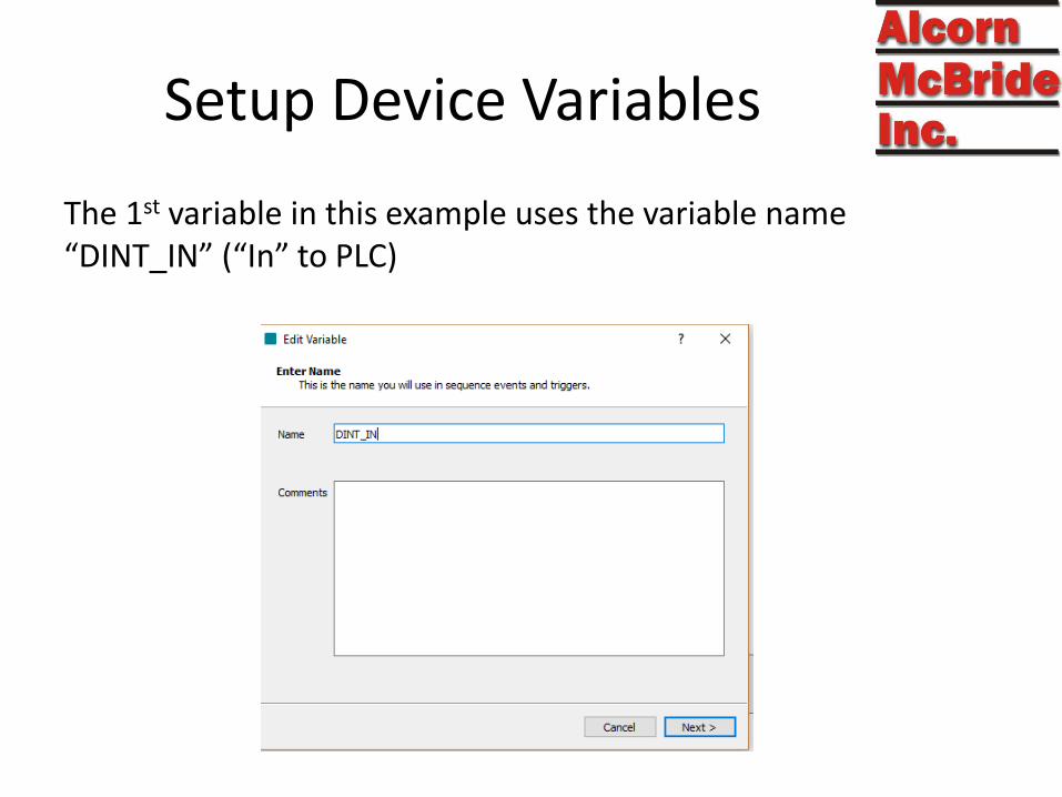
Setup Device Variables
The 1st variable in this example uses the variable name “DINT_IN” (“In” to PLC)

Setup Device Variables
“Write” setup is shown below with corresponding Tag “DINT_IN”

Setup Device Variables
Recommended use is PLC Tag of type DINT, array size is 8

Setup Device Variables
The 2nd variable in this example uses the variable name “DINT_OUT” (“Out” from PLC)

Setup Device Variables
“Read” setup is shown below with Tag “DINT_OUT”

Setup Device Variables
Again, recommended use is PLC Tag of type DINT, array size is 8

Setup Device Variables
Resulting Device Variables:

Setup Device Variables
• Click “>“ to expand array members and assign an alias
• Individual Bits or Array members can be aliased

Setup Device Variables
• Click “>“ again to expand individual items
• Individual bits can also have an alias name
• Bit aliasing gives 8 (array) times 32 (bits) unique boolean values to be used (256).

PLC Setup
Setup on ControlLogix PLC

PLC Tag Setup
• Use Controller tags, not local tags.
• To match this example:
– Use the name “DINT_IN” as type “DINT” array with an array size of “8”
– Use the name “DINT_OUT” as type “DINT” array with an array size of “8”
– Write data to “DINT_IN”

PLC Tag Setup
• Design your bits inside your tags to be held for at least 0.33 seconds with a timer. Do not just flash them on/off at scan rates.

Script Usage
Using Device Variables in WinScriptLive

Writing Tag Values to PLC
To write a value of a tag on the PLC, simply use the
“Set Variable =“ command.
Sequence “Set Heartbeat” demonstrates this using the aliased PLC1 variable called V16Heartbeat (actually PLC1.DINT_IN[0])

Reading Tag Values from PLC
The value of a tag on the PLC is read automatically.
(After it has been setup as a device variable as shown previously)
You can then use the value to trigger sequences, or display the value, just like any other WinScriptLive variable.

Individual Bits
As an alternative to aliasing, you can also access individual bit values in an array by using the notation:
myTag[1].5
Where “1” is the 2nd slot in the array and “5” is the 6th bit.

Individual Bits
This individual bit can also be aliased in the “Device Variables” screen to a more logical name:

Checking Connection
• Use the Watch List and Live Log to determine if the connection is working correctly.
• The “ConnectionStatus” should read “T3 Connected” in the Watch List

Detailed Notes
Advanced Information
And Special Cases

PLC Setup Notes
Use "Controller" type of PLC Tags and NOT “Program” type when setting up your PLC Tabs.
In the PLC, PLC Variables can be of type:
• SINT (8 bits)
• INT (16bits)
• DINT (32bits)
• BOOL
• STRING
• ARRAYS and UDTs
This must match the type selected in the “Device Variable” setup of WinScriptLive.

PLC Tag Notes
• If you must use local tags for some reason, you have to create a controller level tag for communication, then move data in/out to it from your local tag in one of your routines. Ideally – just use controller tags.
• Array sizes can be increased to 350 total for “In” and “Out”

Maximum Data Notes
A maximum of 1500 bytes of PLC data can sent to/from the V16Pro per frame.
With headers, this results in approximately 116 read/write integer tags with a 5 character name.
If you need more than 116 tags, use an array instead which will give you up to 350 double integer locations.
If more is still needed, setup an additional “Device” to the same PLC.

Efficiency Notes
In the PLC controller, use the DINT data type for integers whenever possible.
PLC controllers execute more efficiently and use less memory when working with 32-bit integers (DINTs).
The most amount of data can be transferred by using full arrays of DINTs. Using individual access to parts of an array results in more overhead.

Script Usage – Manual Commands
If you do not want to use a device variable for a tag , you can always use standard CIP commands as an event.
This is not the recommended method, but can be useful in some cases. For example if you want to only write a certain tag once, or if you only want to set a certain bit when another device other than the V16Pro might be modifying that same integer as well.
Have a look at the “Manual Writes” sequence in the PLC_ControlLogix_Advanced.ws4 script if you’d like to use these commands.
Note: STRING data types can not be used with these commands.

Variable Access Notes
Access can be Read, Write, or Read/Write.
In the case Read/Write, the “value” of the variable used in WinScriptLive is always the confirmed value read from the PLC. Read/Write variables always request a “read” immediately after the “write” regardless of the poll rate.
“Read” variables are set as “Read Only” and cannot be modified in WinScriptLive scripts or watch windows.

Variable Access Notes What Read\Write should be used for:
• Double Checking that your PLC’s value matches the value you have in the V16Pro. (For example, if PLC only was rebooted)
• If the “read” value doesn’t match the V16Pro’s “write” value, a new “write” command is sent.
What Read\Write should NOT be used for:
• Any value that is changed by both the PLC and the V16Pro
• Any integer where you plan to have the PLC change some bits and the V16Pro change others.
• Full Arrays when you plan to partially write from the V16Pro and partially from the PLC
In general, use Read Only if PLC changes the value

Script Usage Notes
Note that a “read” of a variable using polling is not considered a “set” and will only check sequence triggers if the value has actually changed.

Setup Variables/Tags – Custom Types
Custom structures called User Data Types (UDTs) can be used in the following notation:
MyDataCustom.MyINT
This is identical to the notation in the “Tags” screen of RSLogix.
For custom structures, the “Data Type” final is the final data type of interest. For example, if “MyINT” was actually an “INT” type, select “INT” in the “Type” box in WinScript

Setup Variables/Tags – Types
Maximum arrays size is 350 (of DINT size) *
String arrays are not supported.
Writes to “STRING” types will update STRING.LEN property as well as .DATA. Strings written are expected to be null terminated strings.
* Versions of V16Pro firmware < 1.27 support arrays up to size 40