controllogix digital i-o user manual
TRANSCRIPT
ControlLogix Digital I/O Modules
Input Modules
1756-IA16, -IA16I, -IA8D, -IB16, -IB16D, -IB16I, -IB32, -IC16, -IH16I, -IM16I, -IN16, -IV16, -IV32
Output Modules
1756-OA16, -OA16I, -OA8, -OA8D, -OA8E, -OB16D, -OB16E, -OB16I, -OB32, -OB8, -OB8EI, -OC8, -OH8I, -ON8, - OV16E, -OW16I, -OX8I
User Manual
Important User Information Because of the variety of uses for the products described in this publication, those responsible for the application and use of this control equipment must satisfy themselves that all necessary steps have been taken to assure that each application and use meets all performance and safety requirements, including any applicable laws, regulations, codes and standards.
The illustrations, charts, sample programs and layout examples shown in this guide are intended solely for purposes of example. Since there are many variables and requirements associated with any particular installation, Allen-Bradley does not assume responsibility or liability (to include intellectual property liability) for actual use based upon the examples shown in this publication.
Allen-Bradley publication SGI-1.1, Safety Guidelines for the Application, Installation and Maintenance of Solid-State Control (available from your local Allen-Bradley office), describes some important differences between solid-state equipment and electromechanical devices that should be taken into consideration when applying products such as those described in this publication.
Reproduction of the contents of this copyrighted publication, in whole or part, without written permission of Rockwell Automation, is prohibited.
Throughout this manual we use notes to make you aware of safety considerations:
Attention statements help you to:
• identify a hazard
• avoid a hazard
• recognize the consequences
Allen-Bradley is a trademark of Rockwell Automation
ATTENTION
!Identifies information about practices or circumstances that can lead to personal injury or death, property damage or economic loss
IMPORTANT Identifies information that is critical for successful application and understanding of the product.
European Communities (EC) Directive Compliance
If this product has the CE mark it is approved for installation within the European Union and EEA regions. It has been designed and tested to meet the following directives.
EMC Directive
This product is tested to meet the Council Directive 89/336/EC Electromagnetic Compatibility (EMC) by applying the following standards, in whole or in part, documented in a technical construction file:
• EN 50081-2 EMC — Generic Emission Standard, Part 2 — Industrial Environment
• EN 50082-2 EMC — Generic Immunity Standard, Part 2 — Industrial Environment
This product is intended for use in an industrial environment.
Low Voltage Directive
This product is tested to meet Council Directive 73/23/EEC Low Voltage, by applying the safety requirements of EN 61131-2 Programmable Controllers, Part 2 - Equipment Requirements and Tests. For specific information required by EN 61131-2, see the appropriate sections in this publication, as well as the Allen-Bradley publication Industrial Automation Wiring and Grounding Guidelines For Noise Immunity, publication 1770-4.1.
Open style devices must be provided with environmental and safety protection by proper mounting in enclosures designed for specific application conditions. See NEMA Standards publication 250 and IEC publication 529, as applicable, for explanations of the degrees of protection provided by different types of enclosure.
Rockwell Automation Support
Rockwell Automation offers support services worldwide, with over 75 sales/support offices, 512 authorized distributors and 260 authorized systems integrators located throughout the United States alone, as well as Rockwell Automation representatives in every major country in the world.
Local Product Support
Contact your local Rockwell Automation representative for:
• sales and order support
• product technical training
• warranty support
• support service agreements
Technical Product Assistance
If you need to contact Rockwell Automation for technical assistance, please review the troubleshooting information first. If the problem persists, then call your local Rockwell Automation representative.
Your Questions or Comments on this Manual
If you find a problem with this manual, please notify us of it on the enclosed Publication Problem Report.
Summary of Changes
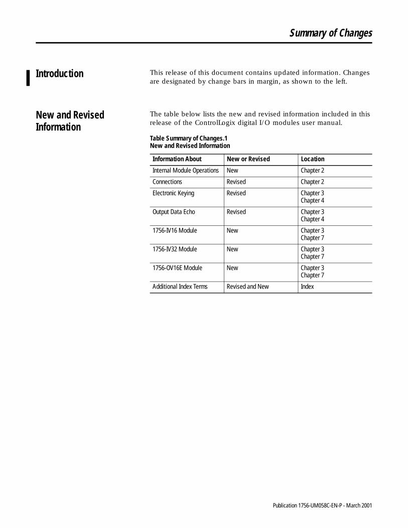
Introduction This release of this document contains updated information. Changes are designated by change bars in margin, as shown to the left.
New and Revised Information
The table below lists the new and revised information included in this release of the ControlLogix digital I/O modules user manual.
Table Summary of Changes.1 New and Revised Information
Information About New or Revised Location
Internal Module Operations New Chapter 2
Connections Revised Chapter 2
Electronic Keying Revised Chapter 3Chapter 4
Output Data Echo Revised Chapter 3Chapter 4
1756-IV16 Module New Chapter 3Chapter 7
1756-IV32 Module New Chapter 3Chapter 7
1756-OV16E Module New Chapter 3Chapter 7
Additional Index Terms Revised and New Index
1 Publication 1756-UM058C-EN-P - March 2001

Summary of Changes 2
Notes:
Publication 1756-UM058C-EN-P - March 2001
Preface
About This User Manual
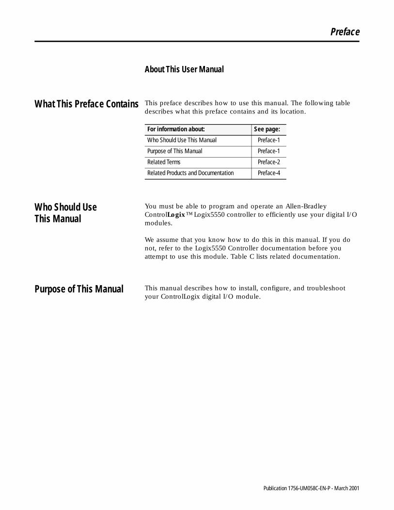
What This Preface Contains This preface describes how to use this manual. The following table describes what this preface contains and its location.
Who Should UseThis Manual
You must be able to program and operate an Allen-Bradley ControlLogix™ Logix5550 controller to efficiently use your digital I/O modules.
We assume that you know how to do this in this manual. If you do not, refer to the Logix5550 Controller documentation before you attempt to use this module. Table C lists related documentation.
Purpose of This Manual This manual describes how to install, configure, and troubleshoot your ControlLogix digital I/O module.
For information about: See page:
Who Should Use This Manual Preface-1
Purpose of This Manual Preface-1
Related Terms Preface-2
Related Products and Documentation Preface-4
1 Publication 1756-UM058C-EN-P - March 2001
Preface 2
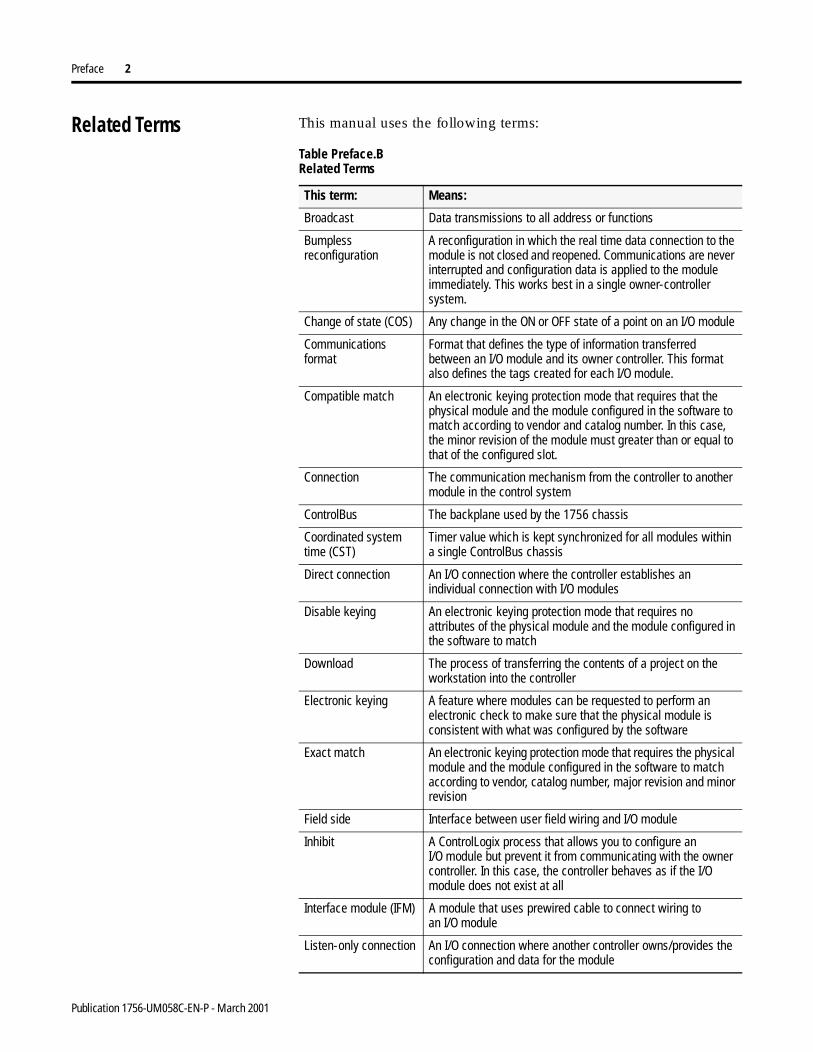
Related Terms This manual uses the following terms:
Table Preface.B Related Terms
This term: Means:
Broadcast Data transmissions to all address or functions
Bumpless reconfiguration
A reconfiguration in which the real time data connection to the module is not closed and reopened. Communications are never interrupted and configuration data is applied to the module immediately. This works best in a single owner-controller system.
Change of state (COS) Any change in the ON or OFF state of a point on an I/O module
Communications format
Format that defines the type of information transferred between an I/O module and its owner controller. This format also defines the tags created for each I/O module.
Compatible match An electronic keying protection mode that requires that the physical module and the module configured in the software to match according to vendor and catalog number. In this case, the minor revision of the module must greater than or equal to that of the configured slot.
Connection The communication mechanism from the controller to another module in the control system
ControlBus The backplane used by the 1756 chassis
Coordinated systemtime (CST)
Timer value which is kept synchronized for all modules within a single ControlBus chassis
Direct connection An I/O connection where the controller establishes an individual connection with I/O modules
Disable keying An electronic keying protection mode that requires no attributes of the physical module and the module configured in the software to match
Download The process of transferring the contents of a project on the workstation into the controller
Electronic keying A feature where modules can be requested to perform an electronic check to make sure that the physical module is consistent with what was configured by the software
Exact match An electronic keying protection mode that requires the physical module and the module configured in the software to match according to vendor, catalog number, major revision and minor revision
Field side Interface between user field wiring and I/O module
Inhibit A ControlLogix process that allows you to configure anI/O module but prevent it from communicating with the owner controller. In this case, the controller behaves as if the I/O module does not exist at all
Interface module (IFM) A module that uses prewired cable to connect wiring toan I/O module
Listen-only connection An I/O connection where another controller owns/provides the configuration and data for the module
Publication 1756-UM058C-EN-P - March 2001
Preface 3
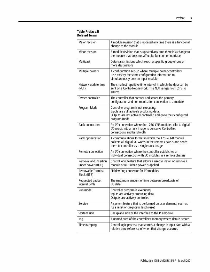
Major revision A module revision that is updated any time there is a functional change to the module
Minor revision A module revision that is updated any time there is a change to the module that does not affect its function or interface
Multicast Data transmissions which reach a specific group of one or more destinations
Multiple owners A configuration set-up where multiple owner controllers use exactly the same configuration information to simultaneously own an input module
Network update time (NUT)
The smallest repetitive time interval in which the data can be sent on a ControlNet network. The NUT ranges from 2ms to 100ms
Owner controller The controller that creates and stores the primary configuration and communication connection to a module
Program Mode Controller program is not executing.Inputs are still actively producing data.Outputs are not actively controlled and go to their configured program mode
Rack connection An I/O connection where the 1756-CNB module collects digital I/O words into a rack image to conserve ControlNet connections and bandwidth
Rack optimization A communications format in which the 1756-CNB module collects all digital I/O words in the remote chassis and sends them to controller as a single rack image
Remote connection An I/O connection where the controller establishes an individual connection with I/O modules in a remote chassis
Removal and insertion under power (RIUP)
ControlLogix feature that allows a user to install or remove a module or RTB while power is applied
Removable Terminal Block (RTB)
Field wiring connector for I/O modules
Requested packet interval (RPI)
The maximum amount of time between broadcasts ofI/O data
Run mode Controller program is executingInputs are actively producing data.Outputs are actively controlled
Service A system feature that is performed on user demand, such as fuse reset or diagnostic latch reset
System side Backplane side of the interface to the I/O module
Tag A named area of the controller’s memory where data is stored
Timestamping ControlLogix process that stamps a change in input data with a relative time reference of when that change occurred
Table Preface.B Related Terms
Publication 1756-UM058C-EN-P - March 2001
Preface 4
Related Products and Documentation
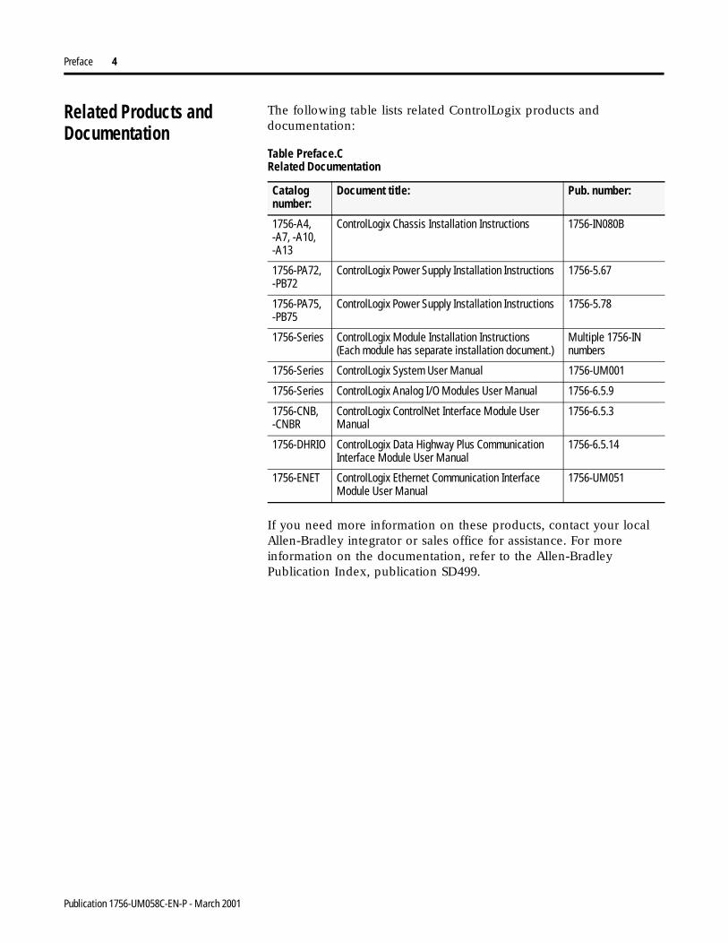
The following table lists related ControlLogix products and documentation:
If you need more information on these products, contact your local Allen-Bradley integrator or sales office for assistance. For more information on the documentation, refer to the Allen-Bradley Publication Index, publication SD499.
Table Preface.C Related Documentation
Catalog number:
Document title: Pub. number:
1756-A4, -A7, -A10, -A13
ControlLogix Chassis Installation Instructions 1756-IN080B
1756-PA72, -PB72
ControlLogix Power Supply Installation Instructions 1756-5.67
1756-PA75, -PB75
ControlLogix Power Supply Installation Instructions 1756-5.78
1756-Series ControlLogix Module Installation Instructions(Each module has separate installation document.)
Multiple 1756-IN numbers
1756-Series ControlLogix System User Manual 1756-UM001
1756-Series ControlLogix Analog I/O Modules User Manual 1756-6.5.9
1756-CNB, -CNBR
ControlLogix ControlNet Interface Module User Manual
1756-6.5.3
1756-DHRIO ControlLogix Data Highway Plus Communication Interface Module User Manual
1756-6.5.14
1756-ENET ControlLogix Ethernet Communication InterfaceModule User Manual
1756-UM051
Publication 1756-UM058C-EN-P - March 2001
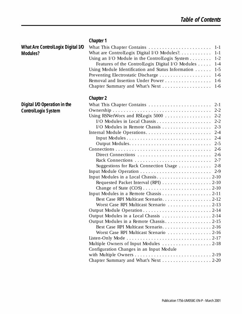
Table of Contents
Chapter 1What Are ControlLogix Digital I/O Modules?
What This Chapter Contains . . . . . . . . . . . . . . . . . . . . . . . 1-1What are ControlLogix Digital I/O Modules?. . . . . . . . . . . . 1-1Using an I/O Module in the ControlLogix System . . . . . . . . 1-2
Features of the ControlLogix Digital I/O Modules . . . . . 1-4Using Module Identification and Status Information . . . . . . 1-5Preventing Electrostatic Discharge . . . . . . . . . . . . . . . . . . . 1-6Removal and Insertion Under Power . . . . . . . . . . . . . . . . . 1-6Chapter Summary and What’s Next . . . . . . . . . . . . . . . . . . 1-6
Chapter 2Digital I/O Operation in theControlLogix System
What This Chapter Contains . . . . . . . . . . . . . . . . . . . . . . . 2-1Ownership . . . . . . . . . . . . . . . . . . . . . . . . . . . . . . . . . . . . 2-2Using RSNetWorx and RSLogix 5000 . . . . . . . . . . . . . . . . . 2-2
I/O Modules in Local Chassis . . . . . . . . . . . . . . . . . . . . 2-2I/O Modules in Remote Chassis . . . . . . . . . . . . . . . . . . 2-3
Internal Module Operations. . . . . . . . . . . . . . . . . . . . . . . . 2-4Input Modules . . . . . . . . . . . . . . . . . . . . . . . . . . . . . . . 2-4Output Modules. . . . . . . . . . . . . . . . . . . . . . . . . . . . . . 2-5
Connections . . . . . . . . . . . . . . . . . . . . . . . . . . . . . . . . . . . 2-6Direct Connections . . . . . . . . . . . . . . . . . . . . . . . . . . . 2-6Rack Connections . . . . . . . . . . . . . . . . . . . . . . . . . . . . 2-7Suggestions for Rack Connection Usage . . . . . . . . . . . . 2-8
Input Module Operation . . . . . . . . . . . . . . . . . . . . . . . . . . 2-9Input Modules in a Local Chassis . . . . . . . . . . . . . . . . . . . . 2-10
Requested Packet Interval (RPI) . . . . . . . . . . . . . . . . . . 2-10Change of State (COS) . . . . . . . . . . . . . . . . . . . . . . . . . 2-10
Input Modules in a Remote Chassis . . . . . . . . . . . . . . . . . . 2-11Best Case RPI Multicast Scenario. . . . . . . . . . . . . . . . . . 2-12Worst Case RPI Multicast Scenario . . . . . . . . . . . . . . . . 2-13
Output Module Operation . . . . . . . . . . . . . . . . . . . . . . . . . 2-14Output Modules in a Local Chassis . . . . . . . . . . . . . . . . . . 2-14Output Modules in a Remote Chassis . . . . . . . . . . . . . . . . . 2-15
Best Case RPI Multicast Scenario. . . . . . . . . . . . . . . . . . 2-16Worst Case RPI Multicast Scenario . . . . . . . . . . . . . . . . 2-16
Listen-Only Mode . . . . . . . . . . . . . . . . . . . . . . . . . . . . . . . 2-17Multiple Owners of Input Modules . . . . . . . . . . . . . . . . . . 2-18Configuration Changes in an Input Modulewith Multiple Owners . . . . . . . . . . . . . . . . . . . . . . . . . . . . 2-19Chapter Summary and What’s Next . . . . . . . . . . . . . . . . . . 2-20
i Publication 1756-UM058C-EN-P - March 2001
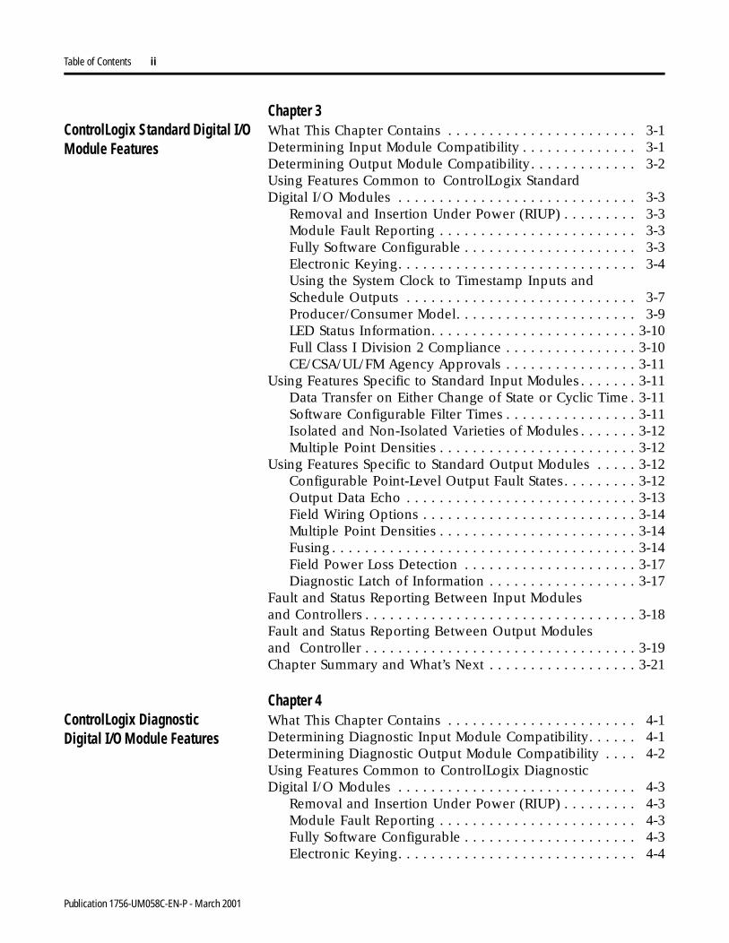
Table of Contents ii
Chapter 3ControlLogix Standard Digital I/OModule Features
What This Chapter Contains . . . . . . . . . . . . . . . . . . . . . . . 3-1Determining Input Module Compatibility . . . . . . . . . . . . . . 3-1Determining Output Module Compatibility . . . . . . . . . . . . . 3-2Using Features Common to ControlLogix StandardDigital I/O Modules . . . . . . . . . . . . . . . . . . . . . . . . . . . . . 3-3
Removal and Insertion Under Power (RIUP) . . . . . . . . . 3-3Module Fault Reporting . . . . . . . . . . . . . . . . . . . . . . . . 3-3Fully Software Configurable . . . . . . . . . . . . . . . . . . . . . 3-3Electronic Keying. . . . . . . . . . . . . . . . . . . . . . . . . . . . . 3-4Using the System Clock to Timestamp Inputs andSchedule Outputs . . . . . . . . . . . . . . . . . . . . . . . . . . . . 3-7Producer/Consumer Model. . . . . . . . . . . . . . . . . . . . . . 3-9LED Status Information. . . . . . . . . . . . . . . . . . . . . . . . . 3-10Full Class I Division 2 Compliance . . . . . . . . . . . . . . . . 3-10CE/CSA/UL/FM Agency Approvals . . . . . . . . . . . . . . . . 3-11
Using Features Specific to Standard Input Modules . . . . . . . 3-11Data Transfer on Either Change of State or Cyclic Time . 3-11Software Configurable Filter Times . . . . . . . . . . . . . . . . 3-11Isolated and Non-Isolated Varieties of Modules . . . . . . . 3-12Multiple Point Densities . . . . . . . . . . . . . . . . . . . . . . . . 3-12
Using Features Specific to Standard Output Modules . . . . . 3-12Configurable Point-Level Output Fault States. . . . . . . . . 3-12Output Data Echo . . . . . . . . . . . . . . . . . . . . . . . . . . . . 3-13Field Wiring Options . . . . . . . . . . . . . . . . . . . . . . . . . . 3-14Multiple Point Densities . . . . . . . . . . . . . . . . . . . . . . . . 3-14Fusing . . . . . . . . . . . . . . . . . . . . . . . . . . . . . . . . . . . . . 3-14Field Power Loss Detection . . . . . . . . . . . . . . . . . . . . . 3-17Diagnostic Latch of Information . . . . . . . . . . . . . . . . . . 3-17
Fault and Status Reporting Between Input Modulesand Controllers . . . . . . . . . . . . . . . . . . . . . . . . . . . . . . . . . 3-18Fault and Status Reporting Between Output Modulesand Controller . . . . . . . . . . . . . . . . . . . . . . . . . . . . . . . . . 3-19Chapter Summary and What’s Next . . . . . . . . . . . . . . . . . . 3-21
Chapter 4ControlLogix DiagnosticDigital I/O Module Features
What This Chapter Contains . . . . . . . . . . . . . . . . . . . . . . . 4-1Determining Diagnostic Input Module Compatibility. . . . . . 4-1Determining Diagnostic Output Module Compatibility . . . . 4-2Using Features Common to ControlLogix DiagnosticDigital I/O Modules . . . . . . . . . . . . . . . . . . . . . . . . . . . . . 4-3
Removal and Insertion Under Power (RIUP) . . . . . . . . . 4-3Module Fault Reporting . . . . . . . . . . . . . . . . . . . . . . . . 4-3Fully Software Configurable . . . . . . . . . . . . . . . . . . . . . 4-3Electronic Keying. . . . . . . . . . . . . . . . . . . . . . . . . . . . . 4-4
Publication 1756-UM058C-EN-P - March 2001
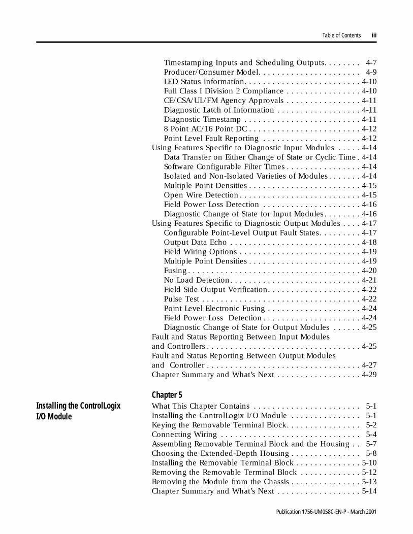
Table of Contents iii
Timestamping Inputs and Scheduling Outputs. . . . . . . . 4-7Producer/Consumer Model. . . . . . . . . . . . . . . . . . . . . . 4-9LED Status Information. . . . . . . . . . . . . . . . . . . . . . . . . 4-10Full Class I Division 2 Compliance . . . . . . . . . . . . . . . . 4-10CE/CSA/UL/FM Agency Approvals . . . . . . . . . . . . . . . . 4-11Diagnostic Latch of Information . . . . . . . . . . . . . . . . . . 4-11Diagnostic Timestamp . . . . . . . . . . . . . . . . . . . . . . . . . 4-118 Point AC/16 Point DC . . . . . . . . . . . . . . . . . . . . . . . . 4-12Point Level Fault Reporting . . . . . . . . . . . . . . . . . . . . . 4-12
Using Features Specific to Diagnostic Input Modules . . . . . 4-14Data Transfer on Either Change of State or Cyclic Time . 4-14Software Configurable Filter Times . . . . . . . . . . . . . . . . 4-14Isolated and Non-Isolated Varieties of Modules . . . . . . . 4-14Multiple Point Densities . . . . . . . . . . . . . . . . . . . . . . . . 4-15Open Wire Detection . . . . . . . . . . . . . . . . . . . . . . . . . . 4-15Field Power Loss Detection . . . . . . . . . . . . . . . . . . . . . 4-16Diagnostic Change of State for Input Modules. . . . . . . . 4-16
Using Features Specific to Diagnostic Output Modules . . . . 4-17Configurable Point-Level Output Fault States. . . . . . . . . 4-17Output Data Echo . . . . . . . . . . . . . . . . . . . . . . . . . . . . 4-18Field Wiring Options . . . . . . . . . . . . . . . . . . . . . . . . . . 4-19Multiple Point Densities . . . . . . . . . . . . . . . . . . . . . . . . 4-19Fusing . . . . . . . . . . . . . . . . . . . . . . . . . . . . . . . . . . . . . 4-20No Load Detection. . . . . . . . . . . . . . . . . . . . . . . . . . . . 4-21Field Side Output Verification. . . . . . . . . . . . . . . . . . . . 4-22Pulse Test . . . . . . . . . . . . . . . . . . . . . . . . . . . . . . . . . . 4-22Point Level Electronic Fusing . . . . . . . . . . . . . . . . . . . . 4-24Field Power Loss Detection . . . . . . . . . . . . . . . . . . . . . 4-24Diagnostic Change of State for Output Modules . . . . . . 4-25
Fault and Status Reporting Between Input Modulesand Controllers . . . . . . . . . . . . . . . . . . . . . . . . . . . . . . . . . 4-25Fault and Status Reporting Between Output Modulesand Controller . . . . . . . . . . . . . . . . . . . . . . . . . . . . . . . . . 4-27Chapter Summary and What’s Next . . . . . . . . . . . . . . . . . . 4-29
Chapter 5Installing the ControlLogix I/O Module
What This Chapter Contains . . . . . . . . . . . . . . . . . . . . . . . 5-1Installing the ControlLogix I/O Module . . . . . . . . . . . . . . . 5-1Keying the Removable Terminal Block. . . . . . . . . . . . . . . . 5-2Connecting Wiring . . . . . . . . . . . . . . . . . . . . . . . . . . . . . . 5-4Assembling Removable Terminal Block and the Housing . . 5-7Choosing the Extended-Depth Housing . . . . . . . . . . . . . . . 5-8Installing the Removable Terminal Block . . . . . . . . . . . . . . 5-10Removing the Removable Terminal Block . . . . . . . . . . . . . 5-12Removing the Module from the Chassis . . . . . . . . . . . . . . . 5-13Chapter Summary and What’s Next . . . . . . . . . . . . . . . . . . 5-14
Publication 1756-UM058C-EN-P - March 2001
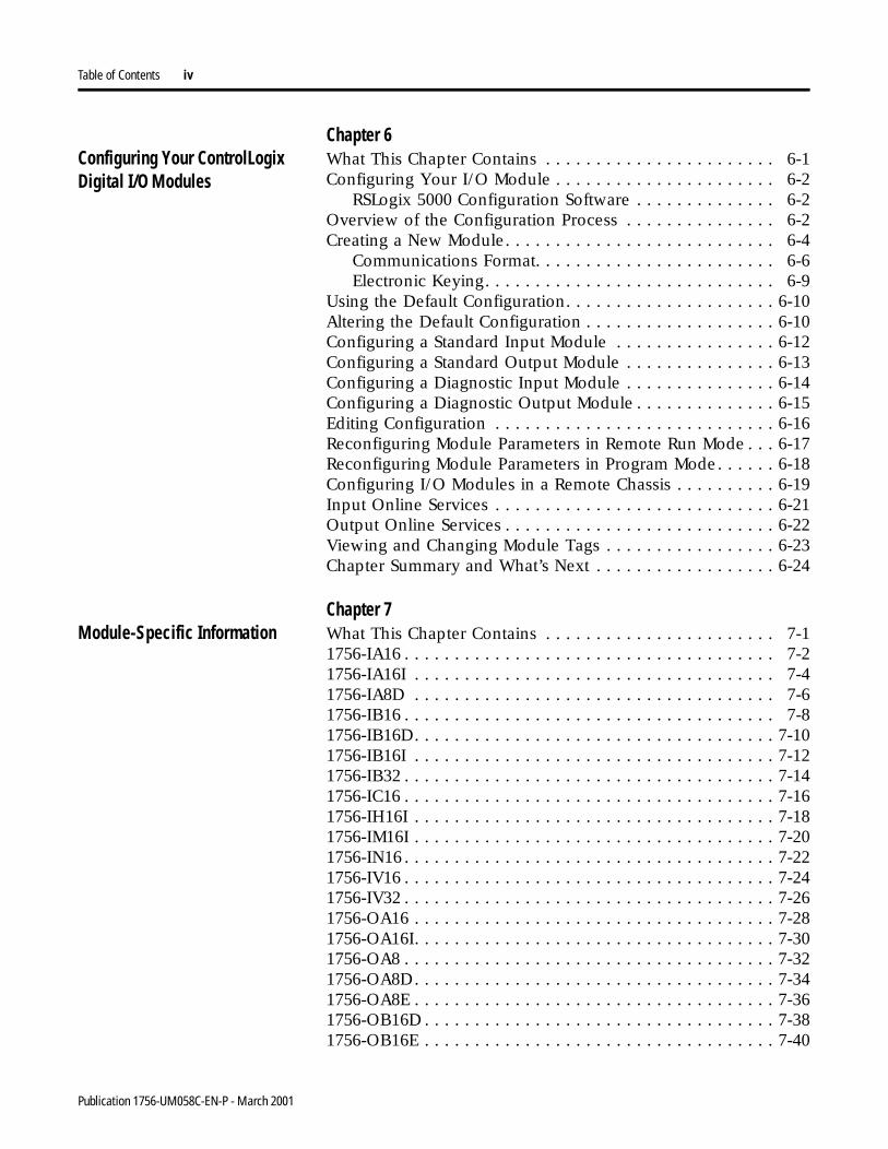
Table of Contents iv
Chapter 6Configuring Your ControlLogixDigital I/O Modules
What This Chapter Contains . . . . . . . . . . . . . . . . . . . . . . . 6-1Configuring Your I/O Module . . . . . . . . . . . . . . . . . . . . . . 6-2
RSLogix 5000 Configuration Software . . . . . . . . . . . . . . 6-2Overview of the Configuration Process . . . . . . . . . . . . . . . 6-2Creating a New Module. . . . . . . . . . . . . . . . . . . . . . . . . . . 6-4
Communications Format. . . . . . . . . . . . . . . . . . . . . . . . 6-6Electronic Keying. . . . . . . . . . . . . . . . . . . . . . . . . . . . . 6-9
Using the Default Configuration. . . . . . . . . . . . . . . . . . . . . 6-10Altering the Default Configuration . . . . . . . . . . . . . . . . . . . 6-10Configuring a Standard Input Module . . . . . . . . . . . . . . . . 6-12Configuring a Standard Output Module . . . . . . . . . . . . . . . 6-13Configuring a Diagnostic Input Module . . . . . . . . . . . . . . . 6-14Configuring a Diagnostic Output Module . . . . . . . . . . . . . . 6-15Editing Configuration . . . . . . . . . . . . . . . . . . . . . . . . . . . . 6-16Reconfiguring Module Parameters in Remote Run Mode . . . 6-17Reconfiguring Module Parameters in Program Mode. . . . . . 6-18Configuring I/O Modules in a Remote Chassis . . . . . . . . . . 6-19Input Online Services . . . . . . . . . . . . . . . . . . . . . . . . . . . . 6-21Output Online Services . . . . . . . . . . . . . . . . . . . . . . . . . . . 6-22Viewing and Changing Module Tags . . . . . . . . . . . . . . . . . 6-23Chapter Summary and What’s Next . . . . . . . . . . . . . . . . . . 6-24
Chapter 7Module-Specific Information What This Chapter Contains . . . . . . . . . . . . . . . . . . . . . . . 7-1
1756-IA16 . . . . . . . . . . . . . . . . . . . . . . . . . . . . . . . . . . . . . 7-21756-IA16I . . . . . . . . . . . . . . . . . . . . . . . . . . . . . . . . . . . . 7-41756-IA8D . . . . . . . . . . . . . . . . . . . . . . . . . . . . . . . . . . . . 7-61756-IB16 . . . . . . . . . . . . . . . . . . . . . . . . . . . . . . . . . . . . . 7-81756-IB16D. . . . . . . . . . . . . . . . . . . . . . . . . . . . . . . . . . . . 7-101756-IB16I . . . . . . . . . . . . . . . . . . . . . . . . . . . . . . . . . . . . 7-121756-IB32 . . . . . . . . . . . . . . . . . . . . . . . . . . . . . . . . . . . . . 7-141756-IC16 . . . . . . . . . . . . . . . . . . . . . . . . . . . . . . . . . . . . . 7-161756-IH16I . . . . . . . . . . . . . . . . . . . . . . . . . . . . . . . . . . . . 7-181756-IM16I . . . . . . . . . . . . . . . . . . . . . . . . . . . . . . . . . . . . 7-201756-IN16 . . . . . . . . . . . . . . . . . . . . . . . . . . . . . . . . . . . . . 7-221756-IV16 . . . . . . . . . . . . . . . . . . . . . . . . . . . . . . . . . . . . . 7-241756-IV32 . . . . . . . . . . . . . . . . . . . . . . . . . . . . . . . . . . . . . 7-261756-OA16 . . . . . . . . . . . . . . . . . . . . . . . . . . . . . . . . . . . . 7-281756-OA16I. . . . . . . . . . . . . . . . . . . . . . . . . . . . . . . . . . . . 7-301756-OA8 . . . . . . . . . . . . . . . . . . . . . . . . . . . . . . . . . . . . . 7-321756-OA8D. . . . . . . . . . . . . . . . . . . . . . . . . . . . . . . . . . . . 7-341756-OA8E . . . . . . . . . . . . . . . . . . . . . . . . . . . . . . . . . . . . 7-361756-OB16D . . . . . . . . . . . . . . . . . . . . . . . . . . . . . . . . . . . 7-381756-OB16E . . . . . . . . . . . . . . . . . . . . . . . . . . . . . . . . . . . 7-40
Publication 1756-UM058C-EN-P - March 2001
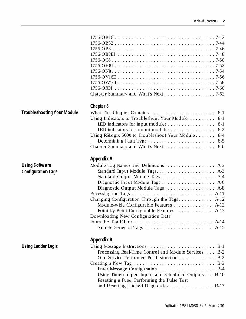
Table of Contents v
1756-OB16I. . . . . . . . . . . . . . . . . . . . . . . . . . . . . . . . . . . . 7-421756-OB32 . . . . . . . . . . . . . . . . . . . . . . . . . . . . . . . . . . . . 7-441756-OB8 . . . . . . . . . . . . . . . . . . . . . . . . . . . . . . . . . . . . . 7-461756-OB8EI . . . . . . . . . . . . . . . . . . . . . . . . . . . . . . . . . . . 7-481756-OC8 . . . . . . . . . . . . . . . . . . . . . . . . . . . . . . . . . . . . . 7-501756-OH8I . . . . . . . . . . . . . . . . . . . . . . . . . . . . . . . . . . . . 7-521756-ON8 . . . . . . . . . . . . . . . . . . . . . . . . . . . . . . . . . . . . . 7-541756-OV16E . . . . . . . . . . . . . . . . . . . . . . . . . . . . . . . . . . . 7-561756-OW16I . . . . . . . . . . . . . . . . . . . . . . . . . . . . . . . . . . . 7-581756-OX8I . . . . . . . . . . . . . . . . . . . . . . . . . . . . . . . . . . . . 7-60Chapter Summary and What’s Next . . . . . . . . . . . . . . . . . . 7-62
Chapter 8Troubleshooting Your Module What This Chapter Contains . . . . . . . . . . . . . . . . . . . . . . . 8-1
Using Indicators to Troubleshoot Your Module . . . . . . . . . 8-1LED indicators for input modules . . . . . . . . . . . . . . . . . 8-1LED indicators for output modules . . . . . . . . . . . . . . . . 8-2
Using RSLogix 5000 to Troubleshoot Your Module . . . . . . . 8-4Determining Fault Type . . . . . . . . . . . . . . . . . . . . . . . . 8-5
Chapter Summary and What’s Next . . . . . . . . . . . . . . . . . . 8-6
Appendix AUsing SoftwareConfiguration Tags
Module Tag Names and Definitions . . . . . . . . . . . . . . . . . . A-3Standard Input Module Tags. . . . . . . . . . . . . . . . . . . . . A-3Standard Output Module Tags . . . . . . . . . . . . . . . . . . . A-4Diagnostic Input Module Tags . . . . . . . . . . . . . . . . . . . A-6Diagnostic Output Module Tags . . . . . . . . . . . . . . . . . . A-8
Accessing the Tags . . . . . . . . . . . . . . . . . . . . . . . . . . . . . A-11Changing Configuration Through the Tags . . . . . . . . . . . . A-12
Module-wide Configurable Features . . . . . . . . . . . . . . A-12Point-by-Point Configurable Features . . . . . . . . . . . . . A-13
Downloading New Configuration DataFrom the Tag Editor . . . . . . . . . . . . . . . . . . . . . . . . . . . . A-14
Sample Series of Tags . . . . . . . . . . . . . . . . . . . . . . . . A-15
Appendix BUsing Ladder Logic Using Message Instructions . . . . . . . . . . . . . . . . . . . . . . . . B-1
Processing Real-Time Control and Module Services . . . . B-2One Service Performed Per Instruction . . . . . . . . . . . . . B-2
Creating a New Tag . . . . . . . . . . . . . . . . . . . . . . . . . . . . . B-3Enter Message Configuration . . . . . . . . . . . . . . . . . . . . B-4Using Timestamped Inputs and Scheduled Outputs . . . B-10Resetting a Fuse, Performing the Pulse Testand Resetting Latched Diagnostics . . . . . . . . . . . . . . . B-13
Publication 1756-UM058C-EN-P - March 2001
Table of Contents vi
Performing a WHO to Retrieve Module Identificationand Status . . . . . . . . . . . . . . . . . . . . . . . . . . . . . . . . . B-14Using Tags in Ladder Logic . . . . . . . . . . . . . . . . . . . . B-16
Appendix CPower Supply Sizing Chart
Appendix DDriving Motor Starters with ControlLogix Digital I/O Modules
Determining the Maximum Number of Motor Starters . . D-2
Index
Publication 1756-UM058C-EN-P - March 2001
Chapter 1
What Are ControlLogix Digital I/O Modules?
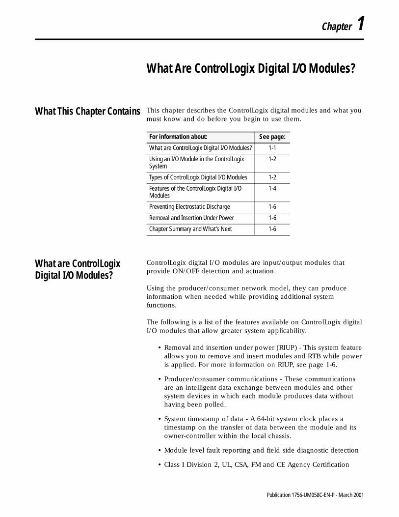
What This Chapter Contains This chapter describes the ControlLogix digital modules and what you must know and do before you begin to use them.
What are ControlLogixDigital I/O Modules?
ControlLogix digital I/O modules are input/output modules that provide ON/OFF detection and actuation.
Using the producer/consumer network model, they can produce information when needed while providing additional system functions.
The following is a list of the features available on ControlLogix digital I/O modules that allow greater system applicability.
• Removal and insertion under power (RIUP) - This system feature allows you to remove and insert modules and RTB while power is applied. For more information on RIUP, see page 1-6.
• Producer/consumer communications - These communications are an intelligent data exchange between modules and other system devices in which each module produces data without having been polled.
• System timestamp of data - A 64-bit system clock places a timestamp on the transfer of data between the module and its owner-controller within the local chassis.
• Module level fault reporting and field side diagnostic detection
• Class I Division 2, UL, CSA, FM and CE Agency Certification
For information about: See page:
What are ControlLogix Digital I/O Modules? 1-1
Using an I/O Module in the ControlLogix System
1-2
Types of ControlLogix Digital I/O Modules 1-2
Features of the ControlLogix Digital I/O Modules
1-4
Preventing Electrostatic Discharge 1-6
Removal and Insertion Under Power 1-6
Chapter Summary and What’s Next 1-6
1 Publication 1756-UM058C-EN-P - March 2001
1-2 What Are ControlLogix Digital I/O Modules?
Using an I/O Module in the ControlLogix System
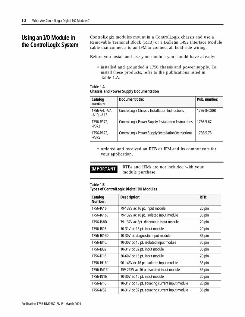
ControlLogix modules mount in a ControlLogix chassis and use a Removable Terminal Block (RTB) or a Bulletin 1492 Interface Module cable that connects to an IFM to connect all field-side wiring.
Before you install and use your module you should have already:
• installed and grounded a 1756 chassis and power supply. To install these products, refer to the publications listed in Table 1.A.
• ordered and received an RTB or IFM and its components for your application.
Table 1.A Chassis and Power Supply Documentation
Catalog number:
Document title: Pub. number:
1756-A4, -A7, -A10, -A13
ControlLogix Chassis Installation Instructions 1756-IN080B
1756-PA72, -PB72
ControlLogix Power Supply Installation Instructions 1756-5.67
1756-PA75, -PB75
ControlLogix Power Supply Installation Instructions 1756-5.78
IMPORTANT RTBs and IFMs are not included with yourmodule purchase.
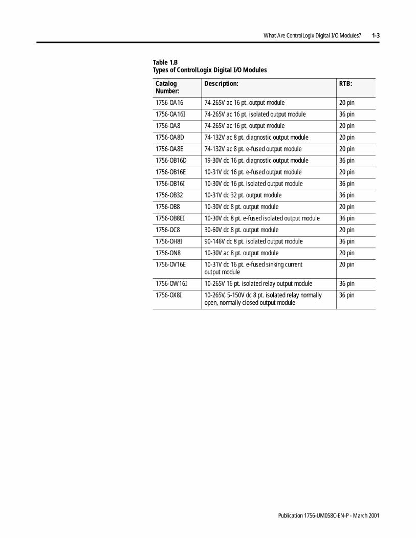
Table 1.B Types of ControlLogix Digital I/O Modules
Catalog Number:
Description: RTB:
1756-IA16 79-132V ac 16 pt. input module 20 pin
1756-IA16I 79-132V ac 16 pt. isolated input module 36 pin
1756-IA8D 79-132V ac 8pt. diagnostic input module 20 pin
1756-IB16 10-31V dc 16 pt. input module 20 pin
1756-IB16D 10-30V dc diagnostic input module 36 pin
1756-IB16I 10-30V dc 16 pt. isolated input module 36 pin
1756-IB32 10-31V dc 32 pt. input module 36 pin
1756-IC16 30-60V dc 16 pt. input module 20 pin
1756-IH16I 90-146V dc 16 pt. isolated input module 36 pin
1756-IM16I 159-265V ac 16 pt. isolated input module 36 pin
1756-IN16 10-30V ac 16 pt. input module 20 pin
1756-IV16 10-31V dc 16 pt. sourcing current input module 20 pin
1756-IV32 10-31V dc 32 pt. sourcing current input module 36 pin
Publication 1756-UM058C-EN-P - March 2001
What Are ControlLogix Digital I/O Modules? 1-3
1756-OA16 74-265V ac 16 pt. output module 20 pin
1756-OA16I 74-265V ac 16 pt. isolated output module 36 pin
1756-OA8 74-265V ac 16 pt. output module 20 pin
1756-OA8D 74-132V ac 8 pt. diagnostic output module 20 pin
1756-OA8E 74-132V ac 8 pt. e-fused output module 20 pin
1756-OB16D 19-30V dc 16 pt. diagnostic output module 36 pin
1756-OB16E 10-31V dc 16 pt. e-fused output module 20 pin
1756-OB16I 10-30V dc 16 pt. isolated output module 36 pin
1756-OB32 10-31V dc 32 pt. output module 36 pin
1756-OB8 10-30V dc 8 pt. output module 20 pin
1756-OB8EI 10-30V dc 8 pt. e-fused isolated output module 36 pin
1756-OC8 30-60V dc 8 pt. output module 20 pin
1756-OH8I 90-146V dc 8 pt. isolated output module 36 pin
1756-ON8 10-30V ac 8 pt. output module 20 pin
1756-OV16E 10-31V dc 16 pt. e-fused sinking current output module
20 pin
1756-OW16I 10-265V 16 pt. isolated relay output module 36 pin
1756-OX8I 10-265V, 5-150V dc 8 pt. isolated relay normally open, normally closed output module
36 pin
Table 1.B Types of ControlLogix Digital I/O Modules
Catalog Number:
Description: RTB:
Publication 1756-UM058C-EN-P - March 2001
1-4 What Are ControlLogix Digital I/O Modules?
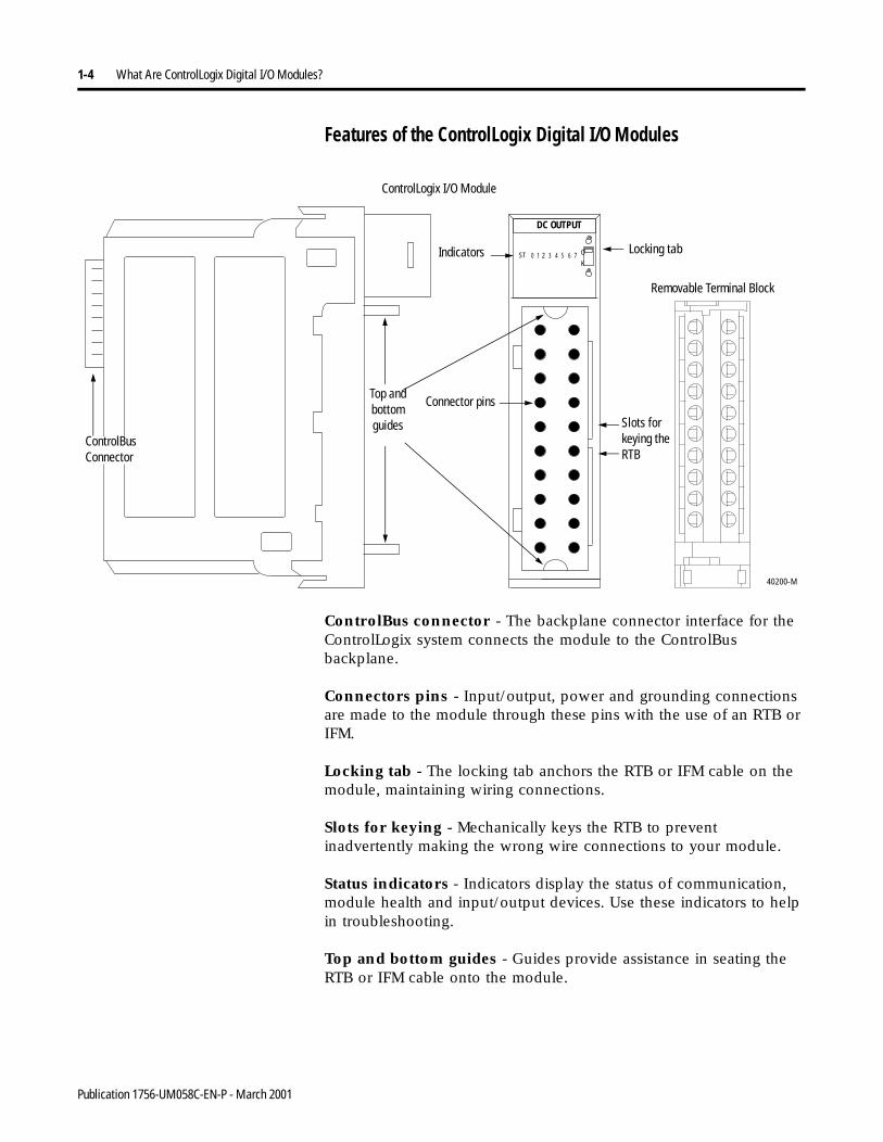
Features of the ControlLogix Digital I/O Modules
ControlBus connector - The backplane connector interface for the ControlLogix system connects the module to the ControlBus backplane.
Connectors pins - Input/output, power and grounding connections are made to the module through these pins with the use of an RTB or IFM.
Locking tab - The locking tab anchors the RTB or IFM cable on the module, maintaining wiring connections.
Slots for keying - Mechanically keys the RTB to prevent inadvertently making the wrong wire connections to your module.
Status indicators - Indicators display the status of communication, module health and input/output devices. Use these indicators to help in troubleshooting.
Top and bottom guides - Guides provide assistance in seating the RTB or IFM cable onto the module.
40200-M
DC OUTPUT
ST O
K0 1 2 3 4 5 6 7
ControlLogix I/O Module
Indicators Locking tab
Removable Terminal Block
Slots for keying the RTB
Connector pinsTop and bottom guides
ControlBus Connector
Publication 1756-UM058C-EN-P - March 2001
What Are ControlLogix Digital I/O Modules? 1-5
Using Module Identification and Status Information
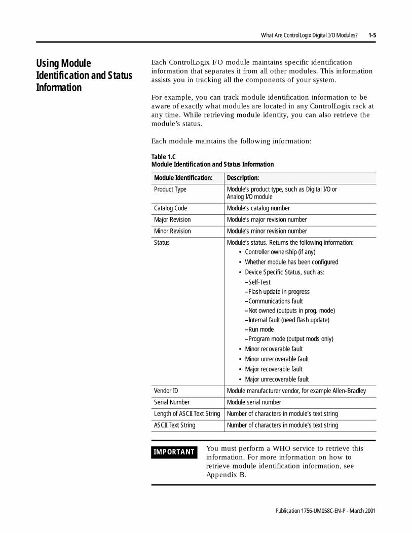
Each ControlLogix I/O module maintains specific identification information that separates it from all other modules. This information assists you in tracking all the components of your system.
For example, you can track module identification information to be aware of exactly what modules are located in any ControlLogix rack at any time. While retrieving module identity, you can also retrieve the module’s status.
Each module maintains the following information:
Table 1.C Module Identification and Status Information
Module Identification: Description:
Product Type Module’s product type, such as Digital I/O orAnalog I/O module
Catalog Code Module’s catalog number
Major Revision Module’s major revision number
Minor Revision Module’s minor revision number
Status Module’s status. Returns the following information:• Controller ownership (if any)
• Whether module has been configured
• Device Specific Status, such as:
–Self-Test–Flash update in progress–Communications fault–Not owned (outputs in prog. mode)–Internal fault (need flash update)–Run mode–Program mode (output mods only)
• Minor recoverable fault
• Minor unrecoverable fault
• Major recoverable fault
• Major unrecoverable fault
Vendor ID Module manufacturer vendor, for example Allen-Bradley
Serial Number Module serial number
Length of ASCII Text String Number of characters in module’s text string
ASCII Text String Number of characters in module’s text string
IMPORTANT You must perform a WHO service to retrieve this information. For more information on how to retrieve module identification information, see Appendix B.
Publication 1756-UM058C-EN-P - March 2001
1-6 What Are ControlLogix Digital I/O Modules?
Preventing Electrostatic Discharge
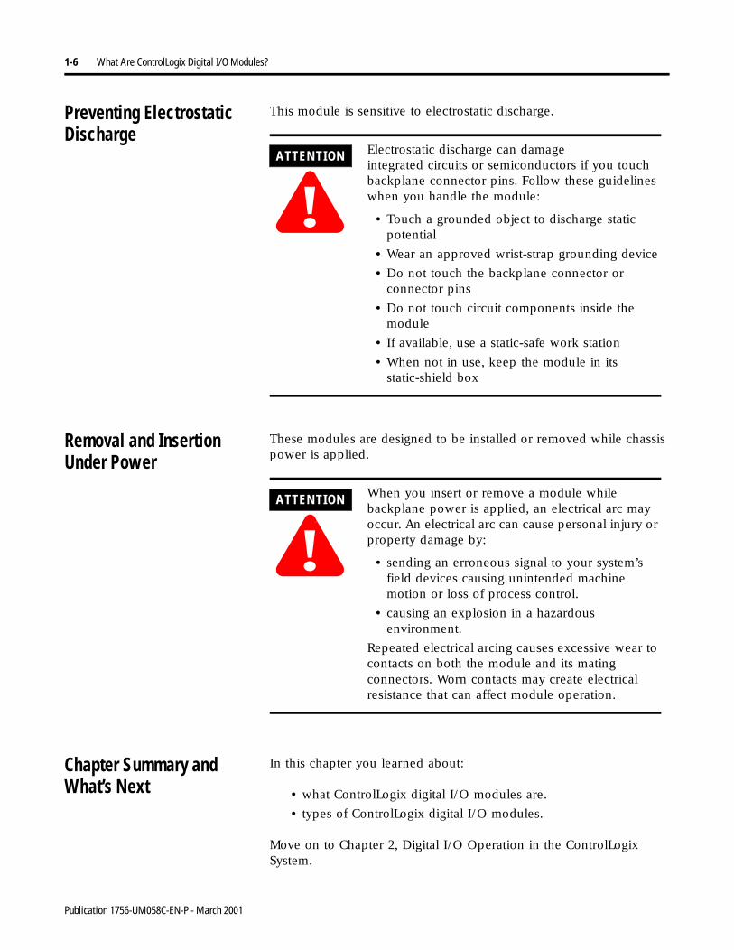
This module is sensitive to electrostatic discharge.
Removal and InsertionUnder Power
These modules are designed to be installed or removed while chassis power is applied.
Chapter Summary andWhat’s Next
In this chapter you learned about:
• what ControlLogix digital I/O modules are.
• types of ControlLogix digital I/O modules.
Move on to Chapter 2, Digital I/O Operation in the ControlLogix System.
ATTENTION
!Electrostatic discharge can damage integrated circuits or semiconductors if you touch backplane connector pins. Follow these guidelines when you handle the module:
• Touch a grounded object to discharge static potential
• Wear an approved wrist-strap grounding device
• Do not touch the backplane connector or connector pins
• Do not touch circuit components inside the module
• If available, use a static-safe work station
• When not in use, keep the module in its static-shield box
ATTENTION
!When you insert or remove a module while backplane power is applied, an electrical arc may occur. An electrical arc can cause personal injury or property damage by:
• sending an erroneous signal to your system’s field devices causing unintended machine motion or loss of process control.
• causing an explosion in a hazardous environment.
Repeated electrical arcing causes excessive wear to contacts on both the module and its mating connectors. Worn contacts may create electrical resistance that can affect module operation.
Publication 1756-UM058C-EN-P - March 2001
Chapter 2
Digital I/O Operation in theControlLogix System
What This Chapter Contains This chapter describes how digital I/O modules work within the ControlLogix system.
For information about: See page:
Ownership 2-2
Using RSNetWorx and RSLogix 5000 2-2
Internal Module Operations 2-4
Direct Connections 2-6
Input Module Operation 2-9
Input Modules in a Local Chassis 2-10
Requested Packet Interval (RPI) 2-10
Change of State (COS) 2-10
Input Modules in a Remote Chassis 2-11
Output Module Operation 2-14
Output Modules in a Local Chassis 2-14
Output Modules in a Remote Chassis 2-15
Listen-Only Mode 2-17
Multiple Owners of Input Modules 2-18
Configuration Changes in an Input Module with Multiple Owners
2-19
Rack Connections 2-7
Suggestions for Rack Connection Usage 2-8
Chapter Summary and What’s Next 2-20
1 Publication 1756-UM058C-EN-P - March 2001
2-2 Digital I/O Operation in the ControlLogix System
Ownership Every I/O module in the ControlLogix system must be owned by a Logix5550 Controller. This owner-controller:
• stores configuration data for every module that it owns.
• can be local or remote in regard to the I/O module’s position.
• sends the I/O module configuration data to define the module’s behavior and begin operation with the control system.
Each ControlLogix I/O module must continuously maintain communication with its owner to operate normally.
Typically, each module in the system will have only 1 owner. Input modules can have more than 1 owner. Output modules, however, are limited to a single owner.
For more information on the increased flexibility provided by multiple owners and the ramifications of using multiple owners, see page 2-13.
Using RSNetWorx andRSLogix 5000
The I/O configuration portion of RSLogix5000 generates the configuration data for each I/O module in the control system, whether the module is located in a local or remote chassis. A remote chassis, also known as networked, contains the I/O module but not the module’s owner controller.
Configuration data is transferred to the controller during the program download and subsequently transferred to the appropriate I/O modules.
I/O Modules in Local Chassis
I/O modules in the same chassis as the controller are ready to run as soon as the configuration data has been downloaded.
Publication 1756-UM058C-EN-P - March 2001
Digital I/O Operation in the ControlLogix System 2-3
I/O Modules in Remote Chassis
You must run RSNetWorx to enable I/O modules in the networked chassis. Running RSNetWorx transfers configuration data to networked modules and establishes a Network Update Time (NUT) for ControlNet. The NUT is compliant with the desired communications options specified for each module during configuration.
Follow these guidelines when configuring I/O modules:
1. Configure all I/O modules for a given controller using RSLogix 5000 and download that information to the controller.
2. If the I/O configuration data references a module in a remote chassis, run RSNetWorx.
IMPORTANT If you are not using I/O modules in a networked chassis, running RSNetWorx is not necessary. However, anytime a controller references an I/O module in a networked chassis, you must run RSNetWorx to configure ControlNet.
IMPORTANT RSNetWorx must be run whenever a new module is added to a networked chassis. When a module is permanently removed from a remote chassis, we recommend that Networx be run to optimize the allocation of network bandwidth.
Publication 1756-UM058C-EN-P - March 2001
2-4 Digital I/O Operation in the ControlLogix System
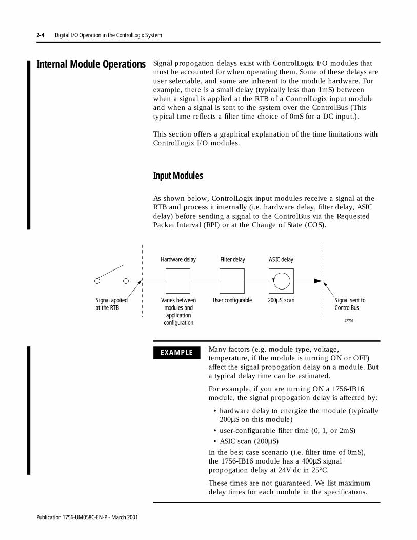
Internal Module Operations Signal propogation delays exist with ControlLogix I/O modules that must be accounted for when operating them. Some of these delays are user selectable, and some are inherent to the module hardware. For example, there is a small delay (typically less than 1mS) between when a signal is applied at the RTB of a ControlLogix input module and when a signal is sent to the system over the ControlBus (This typical time reflects a filter time choice of 0mS for a DC input.).
This section offers a graphical explanation of the time limitations with ControlLogix I/O modules.
Input Modules
As shown below, ControlLogix input modules receive a signal at the RTB and process it internally (i.e. hardware delay, filter delay, ASIC delay) before sending a signal to the ControlBus via the Requested Packet Interval (RPI) or at the Change of State (COS).
Hardware delay Filter delay ASIC delay
42701
User configurable 200µS scanSignal applied at the RTB
Signal sent to ControlBus
Varies between modules and application
configuration
EXAMPLE Many factors (e.g. module type, voltage, temperature, if the module is turning ON or OFF) affect the signal propogation delay on a module. But a typical delay time can be estimated.
For example, if you are turning ON a 1756-IB16 module, the signal propogation delay is affected by:
• hardware delay to energize the module (typically 200µS on this module)
• user-configurable filter time (0, 1, or 2mS)
• ASIC scan (200µS)
In the best case scenario (i.e. filter time of 0mS),the 1756-IB16 module has a 400µS signal propogation delay at 24V dc in 25°C.
These times are not guaranteed. We list maximum delay times for each module in the specificatons.
Publication 1756-UM058C-EN-P - March 2001
Digital I/O Operation in the ControlLogix System 2-5
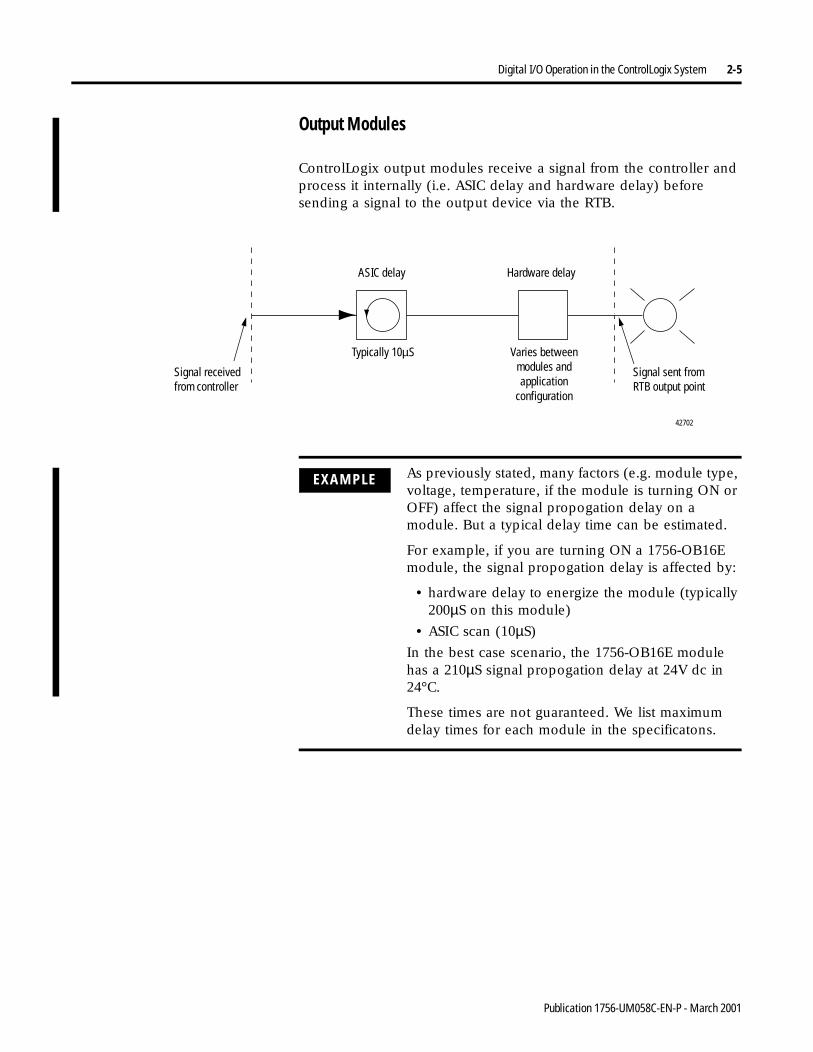
Output Modules
ControlLogix output modules receive a signal from the controller and process it internally (i.e. ASIC delay and hardware delay) before sending a signal to the output device via the RTB.
Hardware delayASIC delay
42702
Typically 10µS
Signal sent from RTB output point
Signal received from controller
Varies between modules and application
configuration
EXAMPLE As previously stated, many factors (e.g. module type, voltage, temperature, if the module is turning ON or OFF) affect the signal propogation delay on a module. But a typical delay time can be estimated.
For example, if you are turning ON a 1756-OB16E module, the signal propogation delay is affected by:
• hardware delay to energize the module (typically 200µS on this module)
• ASIC scan (10µS)
In the best case scenario, the 1756-OB16E module has a 210µS signal propogation delay at 24V dc in 24°C.
These times are not guaranteed. We list maximum delay times for each module in the specificatons.
Publication 1756-UM058C-EN-P - March 2001
2-6 Digital I/O Operation in the ControlLogix System
Connections A connection is the data transfer link between a controller and the device that occupies the slot that the configuration data references, in this case, the I/O module. There are two types of connections:
• Direct Connections
• Rack Connections
The following sections describe each type of connection. See Table 2.A on page 2-9 for differences between connection types. The table also lists the advantages and disadvantages of each type.
Direct Connections
A direct connection is a real-time data transfer link between the controller and the device that occupies the slot that the configuration data references. When module configuration data is downloaded to an owner-controller, the controller attempts to establish a direct connection to each of the modules referenced by the data.
If a controller has configuration data referencing a slot in the control system, the controller periodically checks for the presence of a device there. When a device’s presence is detected there, the controller automatically sends the configuration data.
If the data is appropriate to the module found in the slot, a connection is made and operation begins. If the configuration data is not appropriate, the data is rejected and an error message displays in the software. In this case, the configuration data can be inappropriate for any of a number of reasons. For example, a module’s configuration data may be appropriate except for a mismatch in electronic keying that prevents normal operation.
The controller maintains and monitors its connection with a module. Any break in the connection, such as module faults or removal of the module from the chassis while under power, causes the controller to set fault status bits in the data area associated with the module. The RSLogix 5000 software monitors this data area to annunciate the modules’ failures.
IMPORTANT While a Logix5550 controller allows up to 250 bidirectional connections, each individual I/O module allows 16 bidirectional connections.
Publication 1756-UM058C-EN-P - March 2001
Digital I/O Operation in the ControlLogix System 2-7
Rack Connections
When a digital I/O module is located in a remote chassis (with respect to its owner), you may select rack optimization or listen-only rack optimization in the Communications Format field during initial module configuration. This depends on the bridge module (1756-CNB) configuration. If the CNB is selected for Listen-Only rack option, then the I/O module only allows the Listen-Only rack option.
A rack connection economizes connection usage between the owner and digital I/O in the remote chassis. Rather than having several direct connections with individual RPI values, the owner has a single rack connection with a single RPI value. That RPI value accommodates all digital I/O modules in the rack connection.
The input (or data echo) information is limited to general faults and data. No additional status (e.g. diagnostic) is available.
IMPORTANT Because rack connections are only applicable in applications that use a remote chassis, you must configure the Communications Format for both the remote I/O module and the remote 1756-CNB module.
Make sure you configure both modules for Rack Optimization. If you choose a different Communications Format for each, the controller makes two connections to the same chassis (one for each format) and the same data travels across ControlNet.
If you use Rack Optimization for both modules, you preserve bandwidth and configure your system to operate more efficiently.
IMPORTANT Each controller can only establish 255 connections, in any combination of direct or rack. In other words, you can use a rack connection between an owner controller and multiple remote I/O modules while simultaneously using a direct connection between that same controller and any other I/O modules in the same remote chassis.
Publication 1756-UM058C-EN-P - March 2001
2-8 Digital I/O Operation in the ControlLogix System
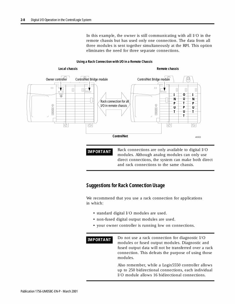
In this example, the owner is still communicating with all I/O in the remote chassis but has used only one connection. The data from all three modules is sent together simultaneously at the RPI. This option eliminates the need for three separate connections.
Suggestions for Rack Connection Usage
We recommend that you use a rack connection for applicationsin which:
• standard digital I/O modules are used.
• non-fused digital output modules are used.
• your owner controller is running low on connections.
Using a Rack Connection with I/O in a Remote Chassis
Local chassis Remote chassis
INPUT
INPUT
OUTPUT
Rack connection for all I/O in remote chassis
ControlNet 41021
Owner controller ControlNet Bridge module ControlNet Bridge module
IMPORTANT Rack connections are only available to digital I/O modules. Although analog modules can only use direct connections, the system can make both direct and rack connections to the same chassis.
IMPORTANT Do not use a rack connection for diagnostic I/O modules or fused output modules. Diagnostic and fused output data will not be transferred over a rack connection. This defeats the purpose of using those modules.
Also remember, while a Logix5550 controller allows up to 250 bidirectional connections, each individual I/O module allows 16 bidirectional connections.
Publication 1756-UM058C-EN-P - March 2001
Digital I/O Operation in the ControlLogix System 2-9
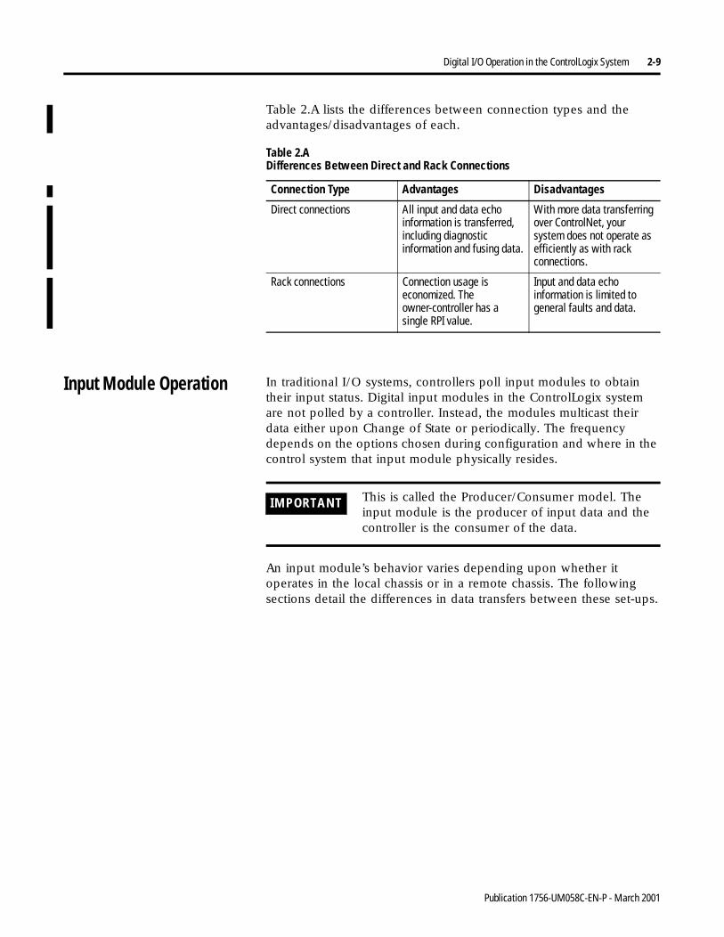
Table 2.A lists the differences between connection types and the advantages/disadvantages of each.
Input Module Operation In traditional I/O systems, controllers poll input modules to obtain their input status. Digital input modules in the ControlLogix system are not polled by a controller. Instead, the modules multicast their data either upon Change of State or periodically. The frequency depends on the options chosen during configuration and where in the control system that input module physically resides.
An input module’s behavior varies depending upon whether it operates in the local chassis or in a remote chassis. The following sections detail the differences in data transfers between these set-ups.
Table 2.A Differences Between Direct and Rack Connections
Connection Type Advantages Disadvantages
Direct connections All input and data echo information is transferred, including diagnostic information and fusing data.
With more data transferring over ControlNet, your system does not operate as efficiently as with rack connections.
Rack connections Connection usage is economized. The owner-controller has a single RPI value.
Input and data echo information is limited to general faults and data.
IMPORTANT This is called the Producer/Consumer model. The input module is the producer of input data and the controller is the consumer of the data.
Publication 1756-UM058C-EN-P - March 2001
2-10 Digital I/O Operation in the ControlLogix System
Input Modules ina Local Chassis
When a module resides in the same chassis as the owner controller, the following two configuration parameters will affect how and when an input module multicasts data:
• Requested Packet Interval (RPI)
• Change of State (COS)
Requested Packet Interval (RPI)
This interval specifies the rate at which a module multicasts its data. The time ranges from 200 microseconds to 750 milliseconds and is sent to the module with all other configuration parameters. When the specified time frame elapses, the module will multicast data. This is also called a cyclic update.
Change of State (COS)
This parameter instructs the module to transfer data whenever a specified input point transitions from ON to OFF or OFF to ON.
COS selection occurs on a per-point basis, but all module data is multicast when any point enabled for COS changes state. COS is more efficient than RPI because it multicasts data only when a change occurs.
IMPORTANT The module COS feature defaults to both ON to OFF and OFF to ON enabled.
IMPORTANT You must specify an RPI regardless of whether you enable COS. If a change does not occur within the RPI timeframe, the module will still multicast data at the rate specified by the RPI.
Publication 1756-UM058C-EN-P - March 2001
Digital I/O Operation in the ControlLogix System 2-11
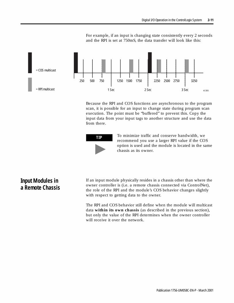
For example, if an input is changing state consistently every 2 seconds and the RPI is set at 750mS, the data transfer will look like this:
Because the RPI and COS functions are asynchronous to the program scan, it is possible for an input to change state during program scan execution. The point must be “buffered” to prevent this. Copy the input data from your input tags to another structure and use the data from there.
Input Modules ina Remote Chassis
If an input module physically resides in a chassis other than where the owner controller is (i.e. a remote chassis connected via ControlNet), the role of the RPI and the module’s COS behavior changes slightly with respect to getting data to the owner.
The RPI and COS behavior still define when the module will multicast data within its own chassis (as described in the previous section), but only the value of the RPI determines when the owner controller will receive it over the network.
41381
= COS multicast
= RPI multicast
250 500 750
1 Sec
1250 1500 1750
2 Sec 3 Sec
2250 2500 2750 3250
TIP To minimize traffic and conserve bandwidth, we recommend you use a larger RPI value if the COS option is used and the module is located in the same chassis as its owner.
Publication 1756-UM058C-EN-P - March 2001
2-12 Digital I/O Operation in the ControlLogix System
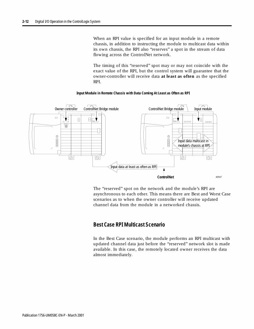
When an RPI value is specified for an input module in a remote chassis, in addition to instructing the module to multicast data within its own chassis, the RPI also “reserves” a spot in the stream of data flowing across the ControlNet network.
The timing of this “reserved” spot may or may not coincide with the exact value of the RPI, but the control system will guarantee that the owner-controller will receive data at least as often as the specified RPI.
The “reserved” spot on the network and the module’s RPI are asynchronous to each other. This means there are Best and Worst Case scenarios as to when the owner controller will receive updated channel data from the module in a networked chassis.
Best Case RPI Multicast Scenario
In the Best Case scenario, the module performs an RPI multicast with updated channel data just before the “reserved” network slot is made available. In this case, the remotely located owner receives the data almost immediately.
40947ControlNet
Input Module in Remote Chassis with Data Coming At Least as Often as RPI
Input data multicast in module’s chassis at RPI
Input data at least as often as RPI
Owner controller ControlNet Bridge module Input moduleControlNet Bridge module
Publication 1756-UM058C-EN-P - March 2001
Digital I/O Operation in the ControlLogix System 2-13
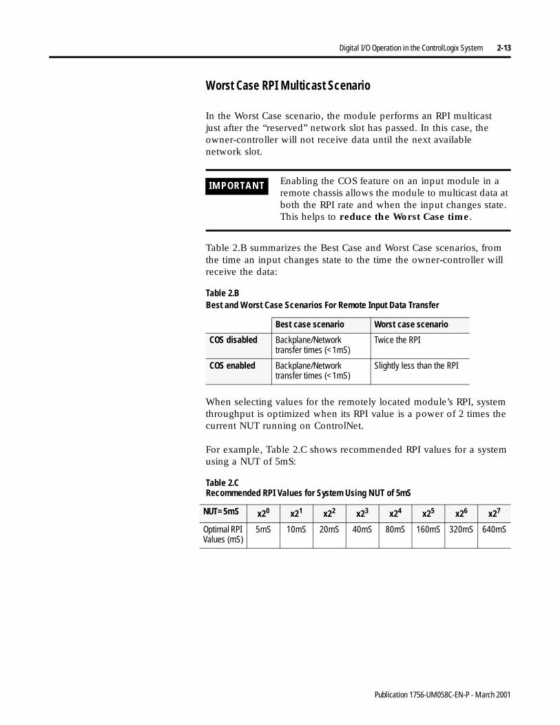
Worst Case RPI Multicast Scenario
In the Worst Case scenario, the module performs an RPI multicastjust after the “reserved” network slot has passed. In this case, the owner-controller will not receive data until the next availablenetwork slot.
Table 2.B summarizes the Best Case and Worst Case scenarios, from the time an input changes state to the time the owner-controller will receive the data:
When selecting values for the remotely located module’s RPI, system throughput is optimized when its RPI value is a power of 2 times the current NUT running on ControlNet.
For example, Table 2.C shows recommended RPI values for a system using a NUT of 5mS:
IMPORTANT Enabling the COS feature on an input module in a remote chassis allows the module to multicast data at both the RPI rate and when the input changes state. This helps to reduce the Worst Case time.
Table 2.B Best and Worst Case Scenarios For Remote Input Data Transfer
Best case scenario Worst case scenario
COS disabled Backplane/Network transfer times (<1mS)
Twice the RPI
COS enabled Backplane/Network transfer times (<1mS)
Slightly less than the RPI
Table 2.C Recommended RPI Values for System Using NUT of 5mS
NUT=5mS x20 x21 x22 x23 x24 x25 x26 x27
Optimal RPI Values (mS)
5mS 10mS 20mS 40mS 80mS 160mS 320mS 640mS
Publication 1756-UM058C-EN-P - March 2001
2-14 Digital I/O Operation in the ControlLogix System
Output Module Operation An owner controller sends output data to an output module when either one of two things occur:
• at the end of every one of its program scans (local chassis only)
and/or
• at the rate specified in the module’s RPI
When an output module physically resides in a remote chassis (with respect to the owner-controller), the owner-controller sends data to the output module only at the RPI rate specified for the module. Updates are not performed at the end of the owner-controller’s program scan.
Whenever the module receives data from the controller, it immediately multicasts the output commands it received to the rest of the system. The actual output data is echoed by the output module as input data and multicast back out onto the network. This is called Output Data Echo. The Output Data Echo also may contain fault and diagnostic information, depending on the module type.
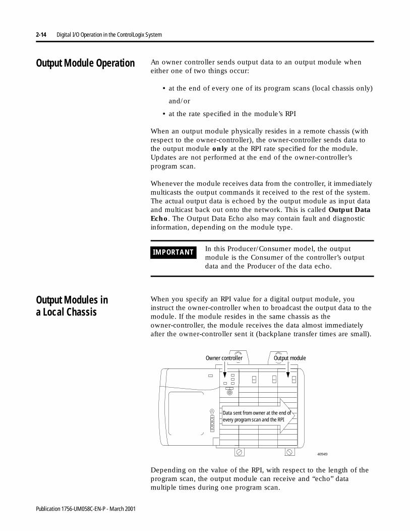
Output Modules ina Local Chassis
When you specify an RPI value for a digital output module, you instruct the owner-controller when to broadcast the output data to the module. If the module resides in the same chassis as the owner-controller, the module receives the data almost immediately after the owner-controller sent it (backplane transfer times are small).
Depending on the value of the RPI, with respect to the length of the program scan, the output module can receive and “echo” data multiple times during one program scan.
IMPORTANT In this Producer/Consumer model, the output module is the Consumer of the controller’s output data and the Producer of the data echo.
40949
Data sent from owner at the end of every program scan and the RPI
Owner controller Output module
Publication 1756-UM058C-EN-P - March 2001
Digital I/O Operation in the ControlLogix System 2-15
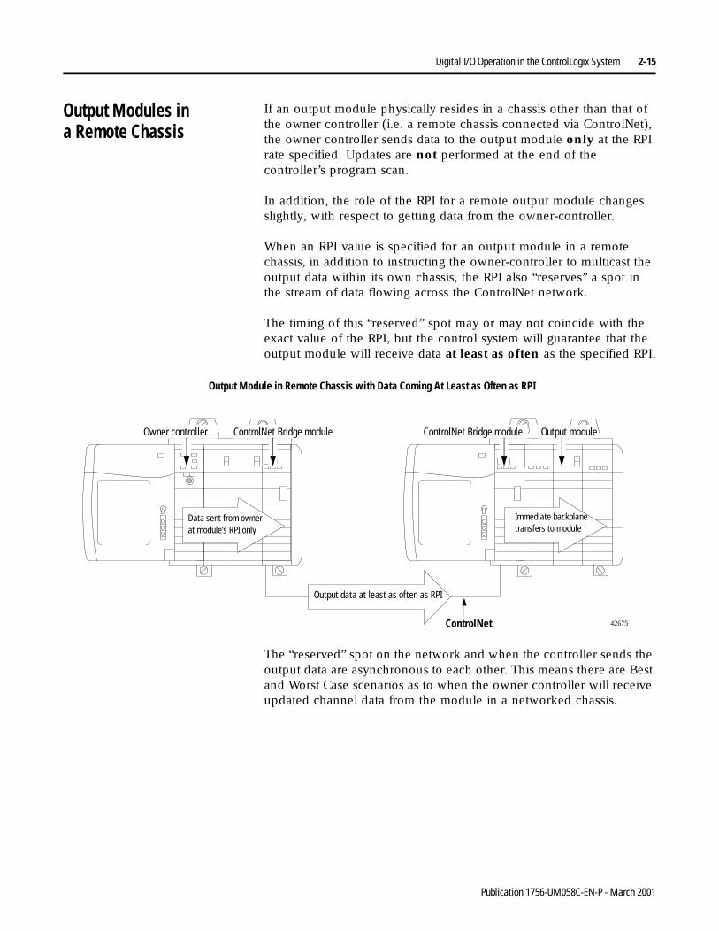
Output Modules ina Remote Chassis
If an output module physically resides in a chassis other than that of the owner controller (i.e. a remote chassis connected via ControlNet), the owner controller sends data to the output module only at the RPI rate specified. Updates are not performed at the end of the controller’s program scan.
In addition, the role of the RPI for a remote output module changes slightly, with respect to getting data from the owner-controller.
When an RPI value is specified for an output module in a remote chassis, in addition to instructing the owner-controller to multicast the output data within its own chassis, the RPI also “reserves” a spot in the stream of data flowing across the ControlNet network.
The timing of this “reserved” spot may or may not coincide with the exact value of the RPI, but the control system will guarantee that the output module will receive data at least as often as the specified RPI.
The “reserved” spot on the network and when the controller sends the output data are asynchronous to each other. This means there are Best and Worst Case scenarios as to when the owner controller will receive updated channel data from the module in a networked chassis.
42675ControlNet
Output Module in Remote Chassis with Data Coming At Least as Often as RPI
Immediate backplane transfers to module
Output data at least as often as RPI
Data sent from owner at module’s RPI only
Owner controller ControlNet Bridge module Output moduleControlNet Bridge module
Publication 1756-UM058C-EN-P - March 2001
2-16 Digital I/O Operation in the ControlLogix System
Best Case RPI Multicast Scenario
In the Best Case scenario, the owner-controller sends the output data just before the “reserved” network slot is made available. In this case, the remotely located output module receives the data almost immediately.
Worst Case RPI Multicast Scenario
In the Worst Case scenario, the owner-controller sends the output data just after the “reserved” network slot has passed. In this case, the output module does not receive data until the next availablenetwork slot.
Table 2.D shows the Best Case and Worst Case times for output data sent from a controller to reach the output module:
Table 2.D Best and Worst Case Times for Remote Output Data Transfer
Best case time Worst case time
Backplane/Network transfer times (<1mS)
RPI rate
IMPORTANT These Best and Worst Case scenarios indicate the time required for output data to transfer from the owner-controller to the module once the owner-controller has produced it. They do not take into account the user program time in the owner-controller.
The receipt of new data is a function of the length of the user program and its asynchronous relationship with the RPI.
Publication 1756-UM058C-EN-P - March 2001
Digital I/O Operation in the ControlLogix System 2-17
Listen-Only Mode Any controller in the system can listen to the data from any I/O module (e.g. input data, “echoed” output data, or “echoed” diagnostic information) even if the controller does not own the module (i.e. it does not have to hold the module’s configuration data to listen to the module).
During the I/O configuration process, you can specify one of several ‘Listen’ modes in the Communication Format field. For more information on Communication Format, see page 6-6.
Choosing a ‘Listen’ mode option allows the controller and module to establish communications without the controller sending any configuration data. In this instance, another controller owns the module being listened to.
IMPORTANT In the Listen-Only mode, controllers will continue to receive data multicast from the I/O module as long as the connection between the owner and I/O module is maintained.
If the connection between owner and module is broken, the module stops multicasting data and connections to all ‘Listening controllers’ are also broken.
Publication 1756-UM058C-EN-P - March 2001
2-18 Digital I/O Operation in the ControlLogix System
Multiple Ownersof Input Modules
Because ‘Listening controllers’ lose their connections to modules when communications with the owner stop, the ControlLogix system will allow you to define more than one owner for input modules.
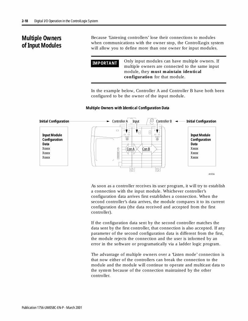
In the example below, Controller A and Controller B have both been configured to be the owner of the input module.
As soon as a controller receives its user program, it will try to establish a connection with the input module. Whichever controller’s configuration data arrives first establishes a connection. When the second controller’s data arrives, the module compares it to its current configuration data (the data received and accepted from the first controller).
If the configuration data sent by the second controller matches the data sent by the first controller, that connection is also accepted. If any parameter of the second configuration data is different from the first, the module rejects the connection and the user is informed by an error in the software or programatically via a ladder logic program.
The advantage of multiple owners over a ‘Listen mode’ connection is that now either of the controllers can break the connection to the module and the module will continue to operate and multicast data to the system because of the connection maintained by the other controller.
IMPORTANT Only input modules can have multiple owners. If multiple owners are connected to the same input module, they must maintain identical configuration for that module.
Multiple Owners with Identical Configuration Data
Input Module Configuration DataXxxxxXxxxxXxxxx
Input Module Configuration DataXxxxxXxxxxXxxxx
41056
Initial Configuration Initial ConfigurationController A Controller BInput
Con A Con B
Publication 1756-UM058C-EN-P - March 2001
Digital I/O Operation in the ControlLogix System 2-19
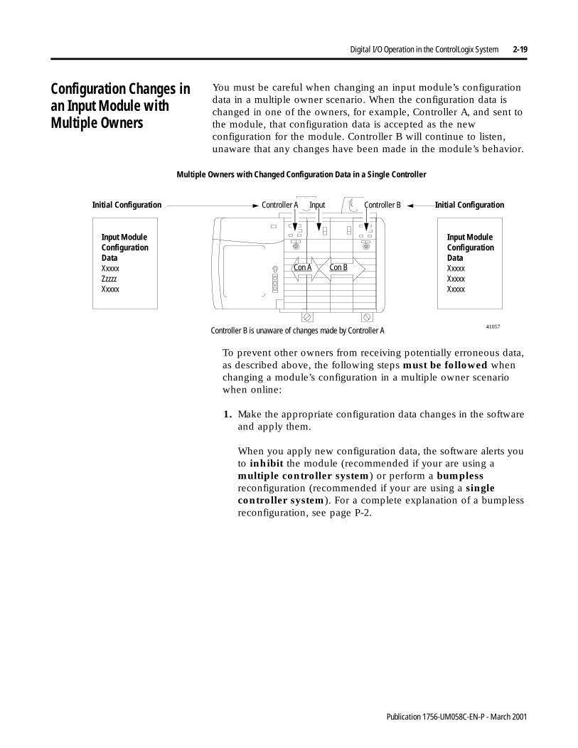
Configuration Changes in an Input Module with Multiple Owners
You must be careful when changing an input module’s configuration data in a multiple owner scenario. When the configuration data is changed in one of the owners, for example, Controller A, and sent to the module, that configuration data is accepted as the new configuration for the module. Controller B will continue to listen, unaware that any changes have been made in the module’s behavior.
To prevent other owners from receiving potentially erroneous data, as described above, the following steps must be followed when changing a module’s configuration in a multiple owner scenario when online:
1. Make the appropriate configuration data changes in the software and apply them.
When you apply new configuration data, the software alerts you to inhibit the module (recommended if your are using a multiple controller system) or perform a bumpless reconfiguration (recommended if your are using a single controller system). For a complete explanation of a bumpless reconfiguration, see page P-2.
Multiple Owners with Changed Configuration Data in a Single Controller
41057Controller B is unaware of changes made by Controller A
Input Module Configuration DataXxxxxZzzzzXxxxx
Input Module Configuration DataXxxxxXxxxxXxxxx
Initial Configuration Initial ConfigurationController A Controller BInput
Con A Con B
Publication 1756-UM058C-EN-P - March 2001
2-20 Digital I/O Operation in the ControlLogix System
2. Repeat step 1 for all owner controllers, making the exact same changes in all controllers.
3. Disable the Inhibit box in each owner’s configuration, if you enabled this box in step 1.
Chapter Summary andWhat’s Next
In this chapter you learned about:
• ownership and connections
• direct connections
• rack connections
• input module operation
• output module operation
Move to Chapter 3, ControlLogix Standard Digital I/O Module Features.
IMPORTANT If all owner controllers have exactly the same configuration after you have made changes, all the controllers will reestablish communication with the input module.
If multiple controllers have different configuration after you have made changes, only one controller (the first one to send changes to the module) will reestablish communications with the input module.
Publication 1756-UM058C-EN-P - March 2001
Chapter 3
ControlLogix Standard Digital I/OModule Features
What This Chapter Contains This chapter describes devices compatible with ControlLogix I/O and features that are specific to various modules.
Determining InputModule Compatibility
ControlLogix digital input modules interface to sensing devices and detect whether they are ON or OFF.
ControlLogix input modules convert ac or dc ON/OFF signals from user devices to appropriate logic level for use within the processor. Typical input devices include:
• proximity switches
• limit switches
• selector switches
• float switches
• pushbutton switches
For information about: See page:
Determining Input Module Compatibility 3-1
Determining Output Module Compatibility 3-2
Using Features Common to ControlLogix Standard Digital I/O Modules
3-3
Using Features Specific to Standard Input Modules
3-11
Using Features Specific to Standard Output Modules
3-12
Fault and Status Reporting Between Input Modules and Controllers
3-18
Fault and Status Reporting Between Output Modules and Controller
3-19
Chapter Summary and What’s Next 3-21
1 Publication 1756-UM058C-EN-P - March 2001
3-2 ControlLogix Standard Digital I/O Module Features
When designing a system using ControlLogix input modules, you must consider:
• the voltage necessary for your application
• whether you need a solid state device
• current leakage
• if your application should use sinking or sourcing wiring.
For more information on compatibility of other Allen-Bradley Company products to ControlLogix input modules, see the I/O Systems Overview, publication CIG-2.1.
Determining OutputModule Compatibility
ControlLogix output modules may be used to drive a variety of output devices. Typical output devices compatible with the ControlLogix outputs include:
• motor starters
• solenoids
• indicators
When designing a system:
• make sure that the ControlLogix outputs can supply the necessary surge and continuous current for proper operation.
• make sure that the surge and continuous current are not exceeded. Damage to the module could result.
When sizing output loads, check the documentation supplied with the output device for the surge and continuous current needed to operate the device.
The ControlLogix outputs are capable of directly driving the ControlLogix inputs. The exceptions are the ac and dc diagnostic input modules. When diagnostics are used a shunt resistor is required for leakage current.
For more information specifically on the compatibility of motor starters to ControlLogix output modules, see Appendix D.
For more information on compatibility of other Allen-Bradley Company products to ControlLogix output modules, see the I/O Systems Overview, publication CIG-2.1.
Publication 1756-UM058C-EN-P - March 2001
ControlLogix Standard Digital I/O Module Features 3-3
Using Features Common to ControlLogix Standard Digital I/O Modules
The following features are common to all ControlLogix standard digital I/O modules:
Removal and Insertion Under Power (RIUP)
All ControlLogix I/O modules may be inserted and removed from the chassis while power is applied. This feature allows greater availability of the overall control system because, while the module is being removed or inserted, there is no additional disruption to the rest of the controlled process.
Module Fault Reporting
ControlLogix digital I/O modules provide both hardware and software indication when a module fault has occurred. Each module’s LED fault indicator and RSLogix 5000 will graphically display this fault and include a fault message describing the nature of the fault.
This feature allows you to determine how your module has been affected and what action should be taken to resume normal operation.
Fully Software Configurable
The RSLogix 5000 software uses a custom, easily understood interface to write configuration. All module features are enabled or disabled through the I/O configuration portion of the software.
You can also use the software to interrogate any module in the system to retrieve
• serial number
• revision information
• catalog number
• vendor identification
• error/fault information
• diagnostic counters.
By eliminating such tasks as setting hardware switches and jumpers, the software makes module configuration easier and more reliable.
Publication 1756-UM058C-EN-P - March 2001
3-4 ControlLogix Standard Digital I/O Module Features
Electronic Keying
Instead of plastic mechanical backplane keys, electronic keying allows the ControlLogix system to control what modules belong in the various slots of a configured system.
During module configuration, you must choose one of the following keying options for your I/O module:
• Exact Match
• Compatible Match
• Disable Keying
The options above are described later in this section.
When the controller attempts to connect to and configure an I/O module (e.g. after program download), the module compares the following parameters before allowing the connection and configuration to be accepted:
• Vendor
• Product Type
• Catalog Number
• Major Revision - Change that affects the module’s function or RSLogix 5000 interface
• Minor Revision - Change that does not affects the module’s function or RSLogix 5000 interface
The comparison is made between the keying information present in the I/O module and the keying information in the controller’s program. This feature can prevent the inadvertent operation of a control system with the wrong module in the wrong slot.
Exact Match
All of the parameters listed above must match or the inserted module will reject a connection to the controller.
Publication 1756-UM058C-EN-P - March 2001

ControlLogix Standard Digital I/O Module Features 3-5
Compatible Match
The Compatible Match mode allows an I/O module to determine whether it can emulate the module defined in the configuration sent from the controller.
With ControlLogix digital I/O modules, the module can emulate older revisions. The module will accept the configuration if the configuration’s major.minor revision is less than or equal to the physical module’s revision.
For example, if the configuration contains a major.minor revision of 2.7, the module inserted into the slot must have a firmware revision of 2.7 or higher for a connection to be made.
TIP We recommend using Compatible Match whenever possible. Remember, though, the module will only work to the level of the configuration.
For example, if a slot is configured for a module with major.minor revision of 2.7 and you insert a module with a major.minor revision of 3.1, the module works at the 2.7 level despite having been previously upgraded.
If possible, we suggest you make sure configuration is updated to match the revision levels of all I/O modules. Failure to do so may not prevent the application from working but may defeat the purpose of upgrading your modules’ revision levels.
Publication 1756-UM058C-EN-P - March 2001

3-6 ControlLogix Standard Digital I/O Module Features
Disable Keying
The inserted module attempts to accept a connection to the controller regardless of its type.
If keying is disabled, a controller makes a connection with most modules of the same type as that used in the slot configuration. For example, if a slot is configured for a 1756-IA16I (standard input module), and a 1756-IB16 (standard input module) is inserted into the slot, the controller established a connection because keying is disabled.
A controller will not establish a connection if any of the following conditions exist, even if keying is disabled:
• The slot is configured for one module type (e.g. input module) and a module of another type (e.g. output module) is inserted in the slot.
• The module inserted into the slot cannot accept some portion of the configuration. For example, if a standard input module is inserted into a slot configured for a diagnostic input module, the controller cannot make a connection because the module cannot accept/process the diagnostic configuration.
ATTENTION
!Be extremely cautious when using the disable keying option; if used incorrectly, this option can lead to personal injury or death, property damage or economic loss.
Publication 1756-UM058C-EN-P - March 2001
ControlLogix Standard Digital I/O Module Features 3-7
Using the System Clock to Timestamp Inputs andSchedule Outputs
Controllers generate a 64-bit Coordinated System Time (CST) for their respective chassis. The CST is a chassis-specific time that is not synchronized with, or in any way connected to, the time generated over ControlNet to establish a NUT, as described in Chapter 2.
You can configure your digital input modules to access the CST and timestamp input data with a relative time reference (i.e. the value of the CST) of when that input data changes state.
Timestamping for a Sequence of Events
The CST can be used to establish a sequence of events occurring at a particular input module point by timestamping the input data. To determine a sequence of events, you must:
• Set the input module’s communications format to: CST Timestamped Input Data
• Enable Change of state for the input point where a sequence will occur (Disable COS for all other points on the module)
IMPORTANT Because only one CST value is returned to the controller when any input point changes state, it is recommended that you use timestamping on only one input point per module.
TIP If you decide to configure multiple input points for COS, your module generates a unique CST each time any of those input points change state, as long as the changes do not occur within 500µS of each other.
If multiple input points configured for COS change state within 500µs of each other, a single CST value is generated for all, making it appear that they changed at exactly the same time.
Publication 1756-UM058C-EN-P - March 2001
3-8 ControlLogix Standard Digital I/O Module Features
Timestamping In Conjunction with Scheduled Outputs
Timestamping can be used in conjunction with the scheduled outputs feature so that after input data changes state and a timestamp occurs, an output point will actuate at some configured time in the future. You can schedule outputs up to 16 seconds into the future.
When you use timestamping of inputs and scheduled outputs, you must:
• choose a Communications Format for each input and output module that allows timestamping. For more information on choosing a Communications Format, see Chapter 6.
• have a controller in the same rack as both I/O modules
• disable Change of State for all input points on the input module except the point being timestamped
TIP For scheduled outputs to work most effectively, remember the following:
• The time to schedule outputs to transition in the future must account for any controller, backplane and network delays.
• The I/O modules must reside in the same rack as the timemaster.
For a detailed example of how to write ladder logic to use these features, see Appendix B.
Publication 1756-UM058C-EN-P - March 2001
ControlLogix Standard Digital I/O Module Features 3-9
Module Major Revision Considerations with Timestamping
When using timestamping for inputs or diagnostic timestamping of I/O modules, remember the following conditions that may occur depending on the module’s Major Revision:
• If the module has a Major Revision = 1, it will always return a positive timestamping value.
• If the module has a Major Revision > 2, it will return a negative timestamping value until the module is synchronized with the owner-controller and the first Change of State condition occurs.
Look at the Module Properties page of RSLogix 5000 to determine if the module has been synchronized with the owner-controller and whether the controller is synchronized with the CST.
For more information on synchronizing owner-controllers and modules with the CST, see the ControlLogix System User Manual, publication 1756-UM001.
Producer/Consumer Model
By using the Producer/Consumer model, ControlLogix I/O modules can produce data without having been polled by a controller first. The modules produce the data and any other owner controller device can decide to consume it.
For example, an input module produces data and any number of processors can consume the data at the same time. This eliminates the need for one processor to send the data to another processor. For a more detailed explanation of this process, see Chapter 2.
Publication 1756-UM058C-EN-P - March 2001
3-10 ControlLogix Standard Digital I/O Module Features
LED Status Information
Each ControlLogix digital I/O module has an LED indicator on the front of the module that allows you to check the module health and operational status of a module. The LED displays vary for each module.
The following status can be checked with the LED indicators:
• I/O status - This yellow display indicates the ON/OFF state of the field device.
• Module status - This green display indicates the module’s communication status.
• Fault status - This display is only found on some modules and indicates the presence or absence of various faults.
• Fuse status - This display is only found on electronically fused modules and indicates the state of the module’s fuse.
For examples of LED indicators on ControlLogix digital I/O modules, see Chapter 7.
Full Class I Division 2 Compliance
All ControlLogix digital I/O modules maintain CSA Class I Division 2 system certification. This allows the ControlLogix system to be placed in an environment other than only a 100% hazard free.
IMPORTANT For the 1756-OA8D and 1756-OA8E modules, the I/O status indicator does not illuminate without field power applied.
IMPORTANT Modules should not be pulled under power, nor should a powered RTB be removed, in a Class I Division 2 environment.
Publication 1756-UM058C-EN-P - March 2001
ControlLogix Standard Digital I/O Module Features 3-11
CE/CSA/UL/FM Agency Approvals
Any ControlLogix digital I/O modules that have obtained CE/CSA/UL/FM agency approval are marked as such. Ultimately, all digital modules will have these agency approvals and be marked accordingly.
Using Features Specific to Standard Input Modules
These features are common to all ControlLogix digital input modules:
Data Transfer on Either Change of State or Cyclic Time
Your ControlLogix input module will send data in one of two ways:
• Requested Packet Interval - a user defined rate at which the module updates the information sent to its owner controller. This is also known as Cyclic Data Transfer.
• Change of State - configurable feature that, when enabled, instructs the module to update its owner controller with new data whenever a specified input point transitions from ON to OFF or OFF to ON. The data will be sent at the RPI rate. By default, this setting is always enabled for input modules.
For a more detailed explanation of these features, see page 2-10.
Software Configurable Filter Times
ON to OFF and OFF to ON filter times can be adjusted throughRSLogix 5000 software for all ControlLogix input modules. These filters improve noise immunity within a signal. A larger filter value affects the length of delay times for signals from these modules.
For an example of how to set filter times, see pages 6-12.
Publication 1756-UM058C-EN-P - March 2001
3-12 ControlLogix Standard Digital I/O Module Features
Isolated and Non-Isolated Varieties of Modules
ControlLogix input modules provide isolated or non-isolated wiring options. Some applications require power for the I/O circuits to originate on separate, isolated, power sources. Because these conditions require separate commons for each channel, some input modules use individual isolation, or point-to-point isolation.
Other types of isolation available with ControlLogix input modules are channel-to-channel isolation and no isolation. Your application determines what type of isolation is necessary and which input module to use.
Multiple Point Densities
ControlLogix input modules use either 8, 16, or 32 point densities for greater flexibility in your application.
Using Features Specific to Standard Output Modules
The following features are common to all ControlLogix standard digital output modules:
Configurable Point-Level Output Fault States
Individual outputs can be independently configured to unique fault states, either ON, OFF or Last State in case of a communications failure or program mode.
IMPORTANT Whenever you inhibit an output module, it enters the program mode and all outputs change to the state configured for the program mode.
For example, if an output module is configured so that the state of the outputs turn off during program mode, whenever that module is inhibited, the outputs will turn off.
Publication 1756-UM058C-EN-P - March 2001
ControlLogix Standard Digital I/O Module Features 3-13
Output Data Echo
During normal operation, when a processor sends an output command out to the ControlLogix system, the output module that is targeted for that command will return the commanded state of the output to the system to verify the module received the command and will try to execute it.
Other devices can use this broadcast signal (via a listen-only connection) to determine the desired state of the output without having to interrogate the owner controller.
Monitor Fault Bits
The Output Data Echo only matches the commanded state of the outputs if the module is operating under normal conditions. If there is a problem with the module, the commanded state and the Output Data Echo may not match.
You can monitor the fault bits for your output points for fault conditions. If a fault occurs, the fault bit is set and your program alerts you to the condition. In this case, the output data echo may not match the commanded state of the outputs.
If there is a mismatch between the commanded state of the outputs and the Output Data Echo, check your output module for the following conditions:
• Communications fault
• Connection is inhibited
• Blown fuse - Module will not turn ON output if overload/short circuit is detected.
• Loss of field power (1756-OA8D and 1756-OA8E only) - Module will not turn ON output if no AC power is detected.
Publication 1756-UM058C-EN-P - March 2001
3-14 ControlLogix Standard Digital I/O Module Features
Field Wiring Options
As with input modules, ControlLogix output modules provide isolated or non-isolated wiring options. I/O modules provide point-to-point, group-to-group, or channel-to-channel wiring isolation. Your specific application will determine what type of isolation is necessary and which output module to use.
Multiple Point Densities
ControlLogix output modules use either 8, 16, or 32 point densities for greater flexibility in your application.
Fusing
Some digital outputs have internal electronic or mechanical fusing to prevent too much current from flowing through the module. This feature protects the module from electrical damage. Other modules require external fusing.
Reset an electronic fuse through RSLogix 5000 configuration software or through ladder logic running on a controller. For an example of how to reset an electronic fuse, see page 6-22.
IMPORTANT Although some ControlLogix I/O modules provide non-isolated field side wiring options, each I/O module maintains internal electrical isolation between the system side and field side.
IMPORTANT Electronic fuses are also reset through a software reset or when the output module is power cycled.
Publication 1756-UM058C-EN-P - March 2001
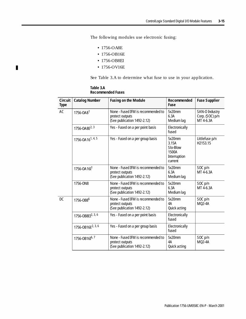
ControlLogix Standard Digital I/O Module Features 3-15
The following modules use electronic fusing:
• 1756-OA8E
• 1756-OB16E
• 1756-OB8EI
• 1756-OV16E
See Table 3.A to determine what fuse to use in your application.
Table 3.A Recommended Fuses
Circuit Type
Catalog Number Fusing on the Module Recommended Fuse
Fuse Supplier
AC 1756-OA81 None - Fused IFM is recommended to protect outputs(See publication 1492-2.12)
5x20mm6.3AMedium lag
SAN-O Industry Corp. (SOC) p/nMT 4-6.3A
1756-OA8E2, 3 Yes - Fused on a per point basis Electronically fused
1756-OA161, 4, 5 Yes - Fused on a per group basis 5x20mm3.15ASlo-Blow1500A Interruption current
Littlefuse p/nH2153.15
1756-OA16I1 None - Fused IFM is recommended to protect outputs(See publication 1492-2.12)
5x20mm6.3AMedium lag
SOC p/nMT 4-6.3A
1756-ON8 None - Fused IFM is recommended to protect outputs(See publication 1492-2.12)
5x20mm6.3AMedium lag
SOC p/nMT 4-6.3A
DC 1756-OB86 None - Fused IFM is recommended to protect outputs(See publication 1492-2.12)
5x20mm4AQuick acting
SOC p/nMQ2-4A
1756-OB8EI2, 3, 6 Yes - Fused on a per point basis Electronically fused
1756-OB16E2, 3, 6 Yes - Fused on a per group basis Electronically fused
1756-OB16I6, 7 None - Fused IFM is recommended to protect outputs(See publication 1492-2.12)
5x20mm4AQuick acting
SOC p/nMQ2-4A
Publication 1756-UM058C-EN-P - March 2001
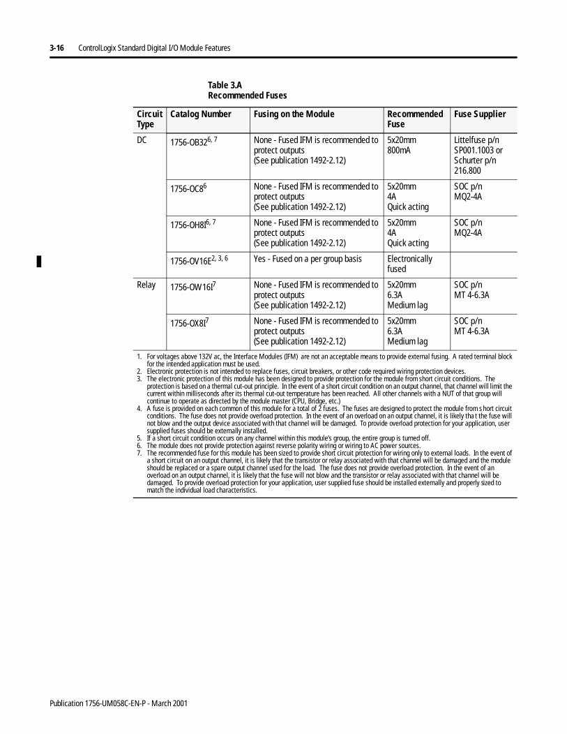
3-16 ControlLogix Standard Digital I/O Module Features
DC 1756-OB326, 7 None - Fused IFM is recommended to protect outputs(See publication 1492-2.12)
5x20mm800mA
Littelfuse p/nSP001.1003 orSchurter p/n216.800
1756-OC86 None - Fused IFM is recommended to protect outputs(See publication 1492-2.12)
5x20mm4AQuick acting
SOC p/nMQ2-4A
1756-OH8I6, 7 None - Fused IFM is recommended to protect outputs(See publication 1492-2.12)
5x20mm4AQuick acting
SOC p/nMQ2-4A
1756-OV16E2, 3, 6 Yes - Fused on a per group basis Electronically fused
Relay 1756-OW16I7 None - Fused IFM is recommended to protect outputs(See publication 1492-2.12)
5x20mm6.3AMedium lag
SOC p/nMT 4-6.3A
1756-OX8I7 None - Fused IFM is recommended to protect outputs(See publication 1492-2.12)
5x20mm6.3AMedium lag
SOC p/nMT 4-6.3A
1. For voltages above 132V ac, the Interface Modules (IFM) are not an acceptable means to provide external fusing. A rated terminal block for the intended application must be used.
2. Electronic protection is not intended to replace fuses, circuit breakers, or other code required wiring protection devices.3. The electronic protection of this module has been designed to provide protection for the module from short circuit conditions. The
protection is based on a thermal cut-out principle. In the event of a short circuit condition on an output channel, that channel will limit the current within milliseconds after its thermal cut-out temperature has been reached. All other channels with a NUT of that group will continue to operate as directed by the module master (CPU, Bridge, etc.)
4. A fuse is provided on each common of this module for a total of 2 fuses. The fuses are designed to protect the module from s hort circuit conditions. The fuse does not provide overload protection. In the event of an overload on an output channel, it is likely tha t the fuse will not blow and the output device associated with that channel will be damaged. To provide overload protection for your application, user supplied fuses should be externally installed.
5. If a short circuit condition occurs on any channel within this module’s group, the entire group is turned off.6. The module does not provide protection against reverse polarity wiring or wiring to AC power sources.7. The recommended fuse for this module has been sized to provide short circuit protection for wiring only to external loads. In the event of
a short circuit on an output channel, it is likely that the transistor or relay associated with that channel will be damaged and the module should be replaced or a spare output channel used for the load. The fuse does not provide overload protection. In the event of an overload on an output channel, it is likely that the fuse will not blow and the transistor or relay associated with that channel will be damaged. To provide overload protection for your application, user supplied fuse should be installed externally and properly sized to match the individual load characteristics.
Table 3.A Recommended Fuses
Circuit Type
Catalog Number Fusing on the Module Recommended Fuse
Fuse Supplier
Publication 1756-UM058C-EN-P - March 2001
ControlLogix Standard Digital I/O Module Features 3-17
Field Power Loss Detection
The Field Power Loss detection feature is found on the following standard output module:
• 1756-OA8E
When field power to the module is lost, or zero cross cannot be detected, a point level fault is sent to the controller to identify the exact point faulted.
For an example of how to enable Field Power Loss detection, see page 6-14.
Diagnostic Latch of Information
The Diagnostic Latch of Information feature is found on the following standard output module:
• 1756-OA8E
Diagnostic Latching allows this module to latch a fault in the set position once it has been triggered, even if the error condition causing the fault to occur disappears.
Latched diagnostic features can be cleared by the Reset Diagnostic Latch service. For an example of how to enable or reset diagnostic latches, see page 6-14.
IMPORTANT Only enable Field Power Loss detection for points that are in use. If this feature is enabled for points that are not in use, you will receive faults for those points during operation.
IMPORTANT Diagnostic latches are also reset through a software reset or when the I/O module’s power is cycled.
Publication 1756-UM058C-EN-P - March 2001
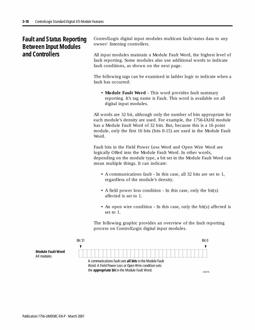
3-18 ControlLogix Standard Digital I/O Module Features
Fault and Status Reporting Between Input Modulesand Controllers
ControlLogix digital input modules multicast fault/status data to any owner/ listening controllers.
All input modules maintain a Module Fault Word, the highest level of fault reporting. Some modules also use additional words to indicatefault conditions, as shown on the next page.
The following tags can be examined in ladder logic to indicate when a fault has occurred:
• Module Fault Word - This word provides fault summary reporting. It’s tag name is Fault. This word is available on all digital input modules.
All words are 32 bit, although only the number of bits appropriate for each module’s density are used. For example, the 1756-IA16I module has a Module Fault Word of 32 bits. But, because this is a 16 point module, only the first 16 bits (bits 0-15) are used in the Module Fault Word.
Fault bits in the Field Power Loss Word and Open Wire Word are logically ORed into the Module Fault Word. In other words, depending on the module type, a bit set in the Module Fault Word can mean multiple things. It can indicate:
• A communications fault - In this case, all 32 bits are set to 1, regardless of the module’s density.
• A field power loss condition - In this case, only the bit(s) affected is set to 1.
• An open wire condition - In this case, only the bit(s) affected is set to 1.
The following graphic provides an overview of the fault reporting process on ControlLogix digital input modules.
Module Fault WordAll modules
42676
Bit 31 Bit 0
A communications fault sets all bits in the Module Fault Word. A Field Power Loss or Open Wire condition sets the appropriate bit in the Module Fault Word.
Publication 1756-UM058C-EN-P - March 2001
ControlLogix Standard Digital I/O Module Features 3-19
Fault and Status Reporting Between Output Modulesand Controller
ControlLogix digital output modules multicast fault/status data to any owner/listening controllers.
All output modules maintain a Module Fault Word, the highest level of fault reporting. Some modules also use additional words to indicate fault conditions, as shown on the next page.
The following tags can be examined in ladder logic to indicate when a fault has occurred:
• Module Fault Word - This word provides fault summary reporting. It’s tag name is Fault. This word is available on all digital output modules.
• Fuse Blown Word - This word indicates a point/group fuse blown on the module. It’s tag name is FuseBlown. This word is only available on 1756-OA16, 1756-OA8E, 1756-OB16E, 1756-OB8EI and 1756-OV16E modules.
For more information on fusing, see page 3-14.
• Field Power Loss Word - This word indicates a loss of field power to a point on the module. It’s tag name is FieldPwrLoss. This word is only available on 1756-OA8E module.
For more information on field power loss, see page 3-17.
All words are 32 bit, although only the number of bits appropriate for each module’s density are used. For example, the 1756-OB8 module has a Module Fault Word of 32 bits. But, because the module is an 8 point module, only the first 8 bits (bits0-7) are used in the Module Fault Word.
Publication 1756-UM058C-EN-P - March 2001
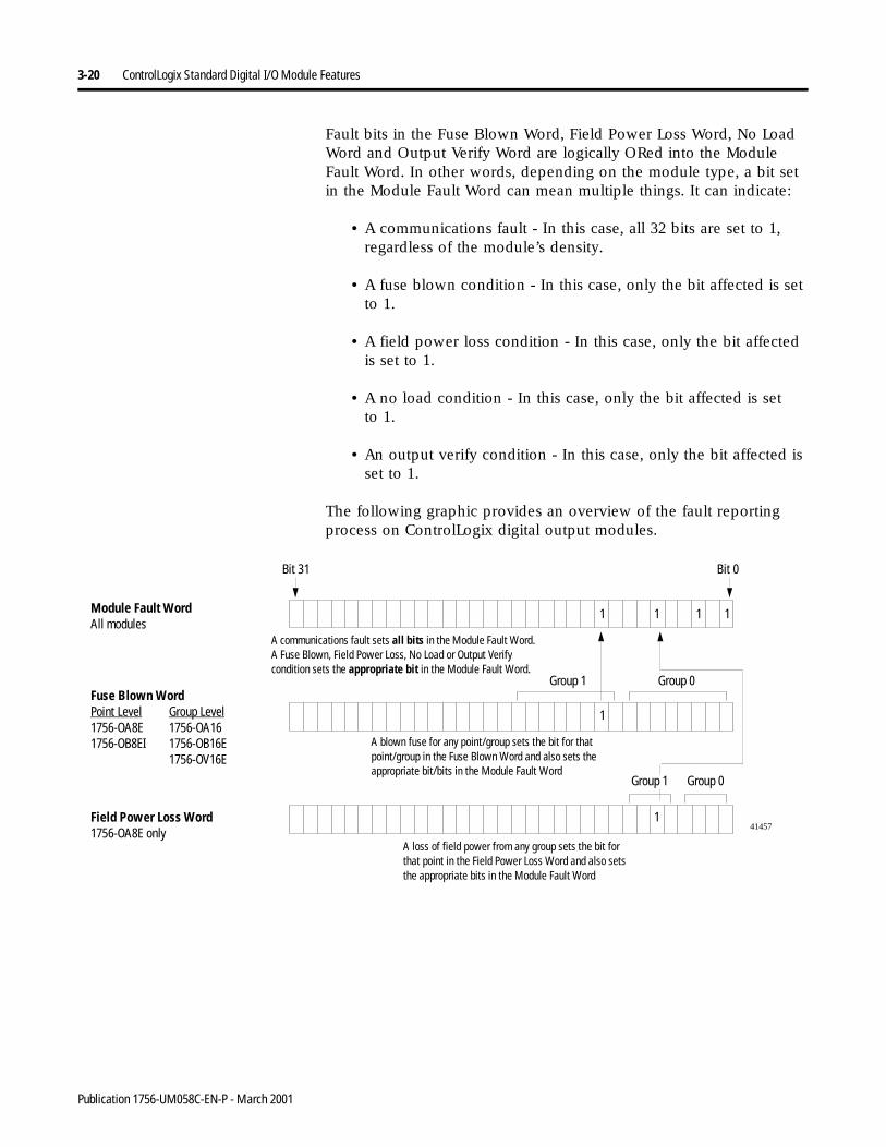
3-20 ControlLogix Standard Digital I/O Module Features
Fault bits in the Fuse Blown Word, Field Power Loss Word, No Load Word and Output Verify Word are logically ORed into the Module Fault Word. In other words, depending on the module type, a bit set in the Module Fault Word can mean multiple things. It can indicate:
• A communications fault - In this case, all 32 bits are set to 1, regardless of the module’s density.
• A fuse blown condition - In this case, only the bit affected is set to 1.
• A field power loss condition - In this case, only the bit affected is set to 1.
• A no load condition - In this case, only the bit affected is setto 1.
• An output verify condition - In this case, only the bit affected is set to 1.
The following graphic provides an overview of the fault reporting process on ControlLogix digital output modules.
Module Fault WordAll modules
Fuse Blown WordPoint Level Group Level1756-OA8E 1756-OA161756-OB8EI 1756-OB16E
1756-OV16E
Field Power Loss Word1756-OA8E only
41457
Bit 31 Bit 0
A blown fuse for any point/group sets the bit for that point/group in the Fuse Blown Word and also sets the appropriate bit/bits in the Module Fault Word
A communications fault sets all bits in the Module Fault Word. A Fuse Blown, Field Power Loss, No Load or Output Verify condition sets the appropriate bit in the Module Fault Word.
A loss of field power from any group sets the bit for that point in the Field Power Loss Word and also sets the appropriate bits in the Module Fault Word
Group 0
1
Group 0Group 1
1
1
1
Group 1
1
1
Publication 1756-UM058C-EN-P - March 2001
ControlLogix Standard Digital I/O Module Features 3-21
Chapter Summary andWhat’s Next
In this chapter you learned about:
• determining input module compatibility
• determining output module compatibility
• using features common to ControlLogix standard digitalI/O modules
• using features specific to ControlLogix standard digitalinput modules
• using features specific to ControlLogix standard digitaloutput modules
Move to Chapter 4, ControlLogix Diagnostic Digital I/O Module Features.
Publication 1756-UM058C-EN-P - March 2001

3-22 ControlLogix Standard Digital I/O Module Features
Notes:
Publication 1756-UM058C-EN-P - March 2001
Chapter 4
ControlLogix Diagnostic Digital I/OModule Features
What This Chapter Contains This chapter describes devices compatible with ControlLogix I/O and features that are specific to various modules.
Determining Diagnostic Input Module Compatibility
ControlLogix digital input modules interface to sensing devices and detect whether they are ON or OFF.
ControlLogix input modules convert ac or dc ON/OFF signals from user devices to appropriate logic level for use within the processor. Typical input devices include:
• proximity switches
• limit switches
• selector switches
• float switches
• pushbutton switches
For information about: See page:
Determining Diagnostic Input Module Compatibility
4-1
Determining Diagnostic Output Module Compatibility
4-2
Using Features Common to ControlLogix Diagnostic Digital I/O Modules
4-3
Using Features Specific to Diagnostic Input Modules
4-14
Using Features Specific to Diagnostic Output Modules
4-17
Fault and Status Reporting Between Input Modules and Controllers
4-25
Fault and Status Reporting Between Output Modules and Controller
4-27
Chapter Summary and What’s Next 4-29
1 Publication 1756-UM058C-EN-P - March 2001
4-2 ControlLogix Diagnostic Digital I/O Module Features
When designing a system using ControlLogix input modules, you must consider:
• the voltage necessary for your application
• whether you need a solid state device
• current leakage
• if your application should use sinking or sourcing wiring.
For more information on compatibility of other Allen-Bradley Company products to ControlLogix input modules, see the I/O Systems Overview, publication CIG-2.1.
Determining Diagnostic Output Module Compatibility
ControlLogix output modules may be used to drive a variety of output devices. Typical output devices compatible with the ControlLogix outputs include:
• motor starters
• solenoids
• indicators
When designing a system:
• make sure that the ControlLogix outputs can supply the necessary surge and continuous current for proper operation.
• make sure that the surge and continuous current are not exceeded. Damage to the module could result.
When sizing output loads, check the documentation supplied with the output device for the surge and continuous current needed to operate the device.
The ControlLogix outputs are capable of directly driving the ControlLogix inputs. The exceptions are the ac and dc diagnostic input modules. When diagnostics are used a shunt resistor is required for leakage current.
For more information on the compatibility of motor starters to ControlLogix output modules, see Appendix D.
For more information on compatibility of other Allen-Bradley Company products to ControlLogix output modules, see the I/O Systems Overview, publication CIG-2.1.
Publication 1756-UM058C-EN-P - March 2001
ControlLogix Diagnostic Digital I/O Module Features 4-3
Using Features Common to ControlLogix DiagnosticDigital I/O Modules
The following features are common to all ControlLogix diagnostic digital I/O modules:
Removal and Insertion Under Power (RIUP)
All ControlLogix I/O diagnostic modules may be inserted and removed from the chassis while power is applied. This feature allows greater availability of the overall control system because, while the module is being removed or inserted, there is no additional disruption to the rest of the controlled process.
Module Fault Reporting
ControlLogix diagnostic digital I/O modules provide both hardware and software indication when a module fault has occurred. Each module’s LED fault indicator and RSLogix 5000 will graphically display this fault and include a fault message describing the nature of the fault.
This feature allows you to determine how your module has been affected and what action should be taken to resume normal operation.
Fully Software Configurable
The RSLogix 5000 software uses a custom, easily understood interface to write configuration. All module features are enabled or disabled through the I/O configuration portion of the software.
You can also use the software to interrogate any module in the system to retrieve
• serial number
• revision information
• catalog number
• vendor identification
• error/fault information
• diagnostic counters.
By eliminating such tasks as setting hardware switches and jumpers, the software makes module configuration easier and more reliable.
Publication 1756-UM058C-EN-P - March 2001
4-4 ControlLogix Diagnostic Digital I/O Module Features
Electronic Keying
Instead of plastic mechanical backplane keys, electronic keying allows the ControlLogix system to control what modules belong in the various slots of a configured system.
During module configuration, you must choose one of the following keying options for your I/O module:
• Exact Match
• Compatible Match
• Disable Keying
The options above are described later in this section.
When the controller attempts to connect to and configure an I/O module (e.g. after program download), the module compares the following parameters before allowing the connection and configuration to be accepted:
• Vendor
• Product Type
• Catalog Number
• Major Revision
• Minor Revision
The comparison is made between the keying information present in the I/O module and the keying information in the controller’s program. This feature can prevent the inadvertent operation of a control system with the wrong module in the wrong slot.
Exact Match
All of the parameters listed above must match or the inserted module will reject a connection to the controller.
Publication 1756-UM058C-EN-P - March 2001
ControlLogix Diagnostic Digital I/O Module Features 4-5
Compatible Match
The Compatible Match mode allows an I/O module to determine whether it can emulate the module defined in the configuration sent from the controller.
With ControlLogix digital I/O modules, the module can emulate older revisions. The module will accept the configuration if the configuration’s major.minor revision is less than or equal to the physical module’s revision.
For example, if the configuration contains a major.minor revision of 2.7, the module inserted into the slot must have minor revision of 2.7 or higher for a connection to be made.
TIP We recommend using Compatible Match whenever possible. Remember, though, the module will only work to the level of the configuration.
For example, if a slot is configured of a module with major.minor revision of 2.7 and you insert a module with a major.minor revision of 3.1, the module works at the 2.7 level despite having been previously upgraded.
If possible, we suggest you make sure configuration is updated to match the revision levels of all I/O modules. Failure to do so may not prevent the application from working but may defeat the purpose of upgrading your modules’ revision levels.
Publication 1756-UM058C-EN-P - March 2001
4-6 ControlLogix Diagnostic Digital I/O Module Features
Disable Keying
The inserted module attempts to accept a connection to the controller regardless of its type.
If keying is disabled, a controller makes a connection with most modules of the same type as that used in the slot configuration. For example, if a slot is configured for a 1756-IA16I (standard input module), and a 1756-IB16 (standard input module) is inserted into the slot, the controller established a connection because keying is disabled.
A controller will not establish a connection if any of the following conditions exist, even if keying is disabled:
• The slot is configured for one module type (e.g. input module) and a module of another type (e.g. output module) is inserted in the slot.
• The module inserted into the slot cannot accept some portion of the configuration. For example, if a standard input module is inserted into a slot configured for a diagnostic input module, the controller cannot make a connection because the module cannot accept/process the diagnostic configuration.
ATTENTION
!Be extremely cautious when using the disable keying option; if used incorrectly, this option can lead to personal injury or death, property damage or economic loss.
Publication 1756-UM058C-EN-P - March 2001
ControlLogix Diagnostic Digital I/O Module Features 4-7
Using the System Clock to Timestamp Inputs andSchedule Outputs
Controllers generate a 64-bit Coordinated System Time (CST) for their respective chassis. The CST is a chassis-specific time that is not synchronized with, or in any way connected to, the time generated over ControlNet to establish a NUT, as described in Chapter 2.
You can configure your digital input modules to access the CST and full diagnostic input data with a relative time reference (i.e. the value of the CST) of when that input data changes state.
Timestamping for a Sequence of Events
The CST can be used to establish a sequence of events occurring at a particular input module point by timestamping the input data. To determine a sequence of events, you must:
• Set the input module’s communications format to: Full diagnostics input data
• Enable Change of state for the input point where a sequence will occur (Disable COS for all other points on the module)
IMPORTANT Because only one CST value is returned to the controller when any input point changes state, it is recommended that you use timestamping on only one input point per module.
TIP If you decide to configure multiple input points for COS, your module generates a unique CST each time any of those input points change state, as long as the changes do not occur within 500µS of each other.
If multiple input points configured for COS change state within 500µs of each other, a single CST value is generated for all, making it appear that they changed at exactly the same time.
Publication 1756-UM058C-EN-P - March 2001
4-8 ControlLogix Diagnostic Digital I/O Module Features
Timestamping In Conjunction with Scheduled Outputs
Timestamping can be used in conjunction with the full diagnostics scheduled outputs feature so that after input data changes state and a timestamp occurs, an output point will actuate at some configured time in the future. You can schedule outputs up to 16 seconds into the future.
When you use timestamping of inputs and scheduled outputs,you must:
• choose a Communications Format for each diagnostic input and diagnostic output module that allows timestamping.For more information on choosing a Communications Format, see Chapter 6.
• have a controller in the same rack as both I/O modules
• disable Change of State for all input points on the input module except the point being timestamped
TIP For scheduled outputs to work most effectively, remember the following:
• The time to schedule outputs to transition in the future must account for any controller, backplane and network delays.
• The I/O modules must reside in the same rack as the timemaster.
For a detailed example of how to write ladder logic to use these features, see Appendix B.
Publication 1756-UM058C-EN-P - March 2001
ControlLogix Diagnostic Digital I/O Module Features 4-9
Module Major Revision Considerations with Timestamping
When using timestamping for inputs or diagnostic timestamping of I/O modules, remember the following conditions that may occur depending on the module’s Major Revision:
• If the module has a Major Revision = 1, it will always return a positive timestamping value.
• If the module has a Major Revision > 2, it will return a negative timestamping value until the module is synchronized with the owner-controller and the first Change of State condition occurs.
Look at the Module Properties page of RSLogix 5000 to determine if the module has been synchronized with the owner-controller and whether the controller is synchronized with the CST.
For more information on synchronizing owner-controllers and modules with the CST, see the ControlLogix System User Manual, publication 1756-UM001.
Producer/Consumer Model
By using the Producer/Consumer model, ControlLogix I/O modules can produce data without having been polled by a controller first. The modules produce the data and any other owner controller device can decide to consume it.
For example, a diagnostic input module produces data and any number of processors can consume the data at the same time. This eliminates the need for one processor to send the data to another processor. For a more detailed explanation of this process, see Chapter 2.
Publication 1756-UM058C-EN-P - March 2001
4-10 ControlLogix Diagnostic Digital I/O Module Features
LED Status Information
Each ControlLogix diagnostic digital I/O module has an LED indicator on the front of the module that allows you to check the module health and operational status of a module. The LED displays vary for each module.
The following status can be checked with the LED indicators:
• I/O status - This yellow display indicates the ON/OFF state of the field device.
• Module status - This green display indicates the module’s communication status.
• Fault status - This display is only found on some modules and indicates the presence or absence of various faults.
• Fuse status - This display is only found on electronically fused modules and indicates the state of the module’s fuse.
For examples of LED indicators on ControlLogix digital I/O modules, see Chapter 7.
Full Class I Division 2 Compliance
All ControlLogix digital I/O modules maintain CSA Class I Division 2 system certification. This allows the ControlLogix system to be placed in an environment other than only a 100% hazard free.
IMPORTANT For the 1756-OA8D and 1756-OA8E modules, the I/O status indicator does not illuminate without field power applied.
IMPORTANT Modules should not be pulled under power, nor should a powered RTB be removed, in a Class I Division 2 environment.
Publication 1756-UM058C-EN-P - March 2001

ControlLogix Diagnostic Digital I/O Module Features 4-11
CE/CSA/UL/FM Agency Approvals
Any ControlLogix digital I/O modules that have obtained CE/CSA/UL/FM agency approval are marked as such. Ultimately, all digital modules will have these agency approvals and be marked accordingly.
Diagnostic Latch of Information
Diagnostic Latching allows diagnostic I/O modules to latch a fault in the set position once it has been triggered, even if the error condition causing the fault to occur disappears.
Latched diagnostic features can be cleared by the Reset Diagnostic Latch service. For an example of how to enable or reset diagnostic latches, see page 6-14 for diagnostic input modules and page 6-15 for diagnostic output modules.
Diagnostic Timestamp
Diagnostic I/O modules can timestamp the time when a fault occurs or when it clears. This feature provides greater accuracy and flexibility in running applications. Modules use the ControlLogix system clock from a local controller to generate timestamps.
To use diagnostic timestamps, you must choose the appropriate Communications Format during initial configuration. For more information on choosing a Communications Format, see Chapter 6.
IMPORTANT Diagnostic latches are also reset through a software reset or when the I/O module’s power is cycled.
Publication 1756-UM058C-EN-P - March 2001
4-12 ControlLogix Diagnostic Digital I/O Module Features
8 Point AC/16 Point DC
Diagnostic ControlLogix digital I/O modules provide various grouping of points on different modules. The 8 point AC modules and 16 point DC modules provide additional flexibility when designing module applications.
Point Level Fault Reporting
Diagnostic I/O modules set bits to indicate when a fault has occurred on a point-by-point basis. The following fault conditions generate their own unique fault bits:
Using these bits in tandem with “data echo” and manually performing a pulse test can help to further isolate the fault.
See Table 4.B for possible diagnostic faults on the 1756-OA8D module.
Table 4.A Unique Fault Bits for I/O Points
Input Points Output Points
Conditions Setting aFault Bit
Open wireField power loss(1756-IA8D only)
Fuse blownNo loadOutput verifyField power loss(1756-OA8D only)
Table 4.B 1756-OA8D Diagnostic Fault Table
Ladder Commands the Output to be ON: Ladder Commands Output to be OFF: Possible Causeof Fault:
1. Output Data Echo returns the state of the output as OFF.
2. Fuse Blown bit is set.
1. Output Data Echo returns the state of the output as OFF1.
2. Pulse Test fails.
Output is shorted to L2
1. Output Data Echo returns the state of the output as ON.
2. Pulse Test fails.2
1. Output Data Echo returns the state of the output as OFF.
2. No Load bit is set.
No Load or output is shorted to L1
Publication 1756-UM058C-EN-P - March 2001
ControlLogix Diagnostic Digital I/O Module Features 4-13
See Table 4.C for possible diagnostic faults on the 1756-OB16D module
1. Output Data Echo returns the state of the output as OFF.
2. No Load shows a Fault.3. Field Power Loss shows a Fault.4. Pulse Test fails.
1. Output Data Echo returns the state of the output as OFF.
2. No Load bit is set.3. Field Power Loss bit is set.4. Pulse Test fails.
L1 or L2 are disconnected or outside the 47-63Hz frequency range
1. Output Data Echo returns the state of the output as ON3.
2. Output Verify4 bit is set.
1. Output Data Echo returns the state of the output as OFF.
2. Pulse Test fails.
Hardware point damage5
1. It is not possible to create a fuse blown fault in the OFF state. If a short circuit occurs, the output point is turned OFF and the fault appears in the OFF state until the point is reset.
2. When pulse test is executed, it is normal operation to see a momentary pulsation on the module display.3. The output cannot turn ON due to hardware point damage.4. Depending on the characteristics of an applied short circuit, an output verify fault could be set until the short circuit is detected by the module and the output
is turned OFF.5. During normal operating conditions, hardware damage should not be possible. An output shorted to L2 may temporarily cause a hardware point fault. See
output shorted to L2 as a possible cause.
Table 4.B 1756-OA8D Diagnostic Fault Table
Ladder Commands the Output to be ON: Ladder Commands Output to be OFF: Possible Causeof Fault:
Table 4.C 1756-OB16D Diagnostic Fault Table
Ladder Commands the Output to be ON: Ladder Commands the Output to be OFF: Possible Causeof Fault:
1. Output Data Echo returns the state of the output as OFF.2. Fuse Blown1 bit is set.
1. Output Data Echo returns the state of the output as OFF2.2. Pulse Test fails3.
Output is shorted to GND
1. Output Data Echo returns the state of the output as ON.
2. Pulse Test fails.
1. Output Data Echo returns the state of the output as OFF.
2. No Load bit is set.3. Pulse Test passes.
One of the following: 1. No Load
2. Output is shorted to DC+
3. No power to the module
1. Output Data Echo returns the state of the output as ON4.
2. Output Verify5 sets a bit.
1. Output Data Echo returns the state of the output as OFF.
2. Pulse Test fails.
Hardware point damage6
1. The electronic protection of this module has been designed to provide protection for the module from short circuit conditions. The protection is based on a thermal cutout principal. In the event of a short circuit condition on an output channel, that channel will limit the current within milliseconds after its thermal cutout temperature has been reached. Other channels could produce a false error on the output verify fault signal due to the supply dropping below the minimum detect level of 19.2V dc. The output channels that are affected by this phenomena will continue to operate as directed by the module master (CPU, Bridge, etc.) What this means is that the output verify fault signals of the other channels should be checked and reset if a short circuit on one channel occurs.
2. It is not possible to create a fuse blown fault in the OFF state. If a short circuit occurs, the output point is turned OFF and the fault appears in the OFF state until that point is reset.
3. When pulse test is executed, it is normal operation to see a momentary pulsation on the module display.4. The output cannot turn ON due to hardware point damage.5. Depending on the characteristics of an applied short circuit, an output verify fault could be set until the short circuit is detected by the module and the
output is turned OFF.6. During normal operating conditions, hardware damage should not be possible. An output shorted to GND may temporarily cause a hardware point fault.
See output shorted to GND as a possible cause.
Publication 1756-UM058C-EN-P - March 2001
4-14 ControlLogix Diagnostic Digital I/O Module Features
Using Features Specific to Diagnostic Input Modules
The following features are available on all ControlLogix diagnostic digital input modules:
Data Transfer on Either Change of State or Cyclic Time
Your ControlLogix input module will send data in one of two ways:
• Requested Packet Interval - a user defined rate at which the module updates the information sent to its owner controller. This is also known as Cyclic Data Transfer.
• Change of State - configurable feature that, when enabled, instructs the module to update its owner controller with new data whenever a specified input point transitions from ON to OFF or OFF to ON. The data will be sent at the RPI rate. The default setting for this feature is always enabled.
For a more detailed explanation of these features, see page 2-10.
Software Configurable Filter Times
ON to OFF and OFF to ON filter times can be adjusted throughRSLogix 5000 software for all ControlLogix diagnostic input modules. These filters improve noise immunity within a signal. A larger filter value affects the length of delay times for signals from these modules.
For an example of how to set filter times, see page 6-14 for diagnostic input modules.
Isolated and Non-Isolated Varieties of Modules
ControlLogix diagnostic input modules provide isolated or non-isolated wiring options. Some applications require power for the I/O circuits to originate on separate, isolated, power sources. Because these conditions require separate commons for each channel, some input modules use individual isolation, or point-to-point isolation.
Other types of isolation available with ControlLogix diagnostic input modules are channel-to-channel isolation and no isolation. Your specific application will determine what type of isolation is necessary and which input module to use.
Publication 1756-UM058C-EN-P - March 2001
ControlLogix Diagnostic Digital I/O Module Features 4-15
Multiple Point Densities
ControlLogix diagnostic input modules use either 8, 16, or 32 point densities for greater flexibility in your application.
Open Wire Detection
Open Wire is used to make sure the field wiring is connected to the module. The field device must provide a minimum leakage current to function properly.
A leakage resistor must be placed across the contacts of an input device. (See each module’s specifications, listed in Chapter 6, for more details.) The resulting current is then expected to exist when the input is open.
When an Open Wire condition is detected, a point-level fault is sent to the controller to identify the exact point fault. This feature has a corresponding tag that can be examined in the user program in the event of a fault. For more information on these tags, see Appendix A.
For an example of how to enable the Open Wire detection diagnostic,see page 6-15.
IMPORTANT If this feature is enabled for points that are not in use, you will receive faults for those points during operation.
Publication 1756-UM058C-EN-P - March 2001
4-16 ControlLogix Diagnostic Digital I/O Module Features
Field Power Loss Detection
Field Power Loss is only found on the 1756-IA8D module.
When field power to the module is lost, a point level fault is sent to the controller to identify the exact point faulted. Only enable Field Power Loss detection for points that are in use.
This feature has a corresponding tag that can be examined in the user program in the event of a fault. For more information on these tags, see Appendix A.
For an example of how to set the Field Power Loss detection diagnostic, see page 6-14.
Diagnostic Change of State for Input Modules
If the Diagnostic Change of State feature is enabled, a diagnostic input module sends new data to the owner controller when one of threeevents occurs:
• Requested Packet Interval - a user defined rate at which the module updates the information sent to its owner controller
• Change of State - configurable feature that, when enabled, instructs the module to update its owner-controller with new data whenever a specified input point transitions from ON to OFF or OFF to ON. The transitioned input data is sent with the next RPI update.
• Diagnostic Change of State - any change in the diagnostics for a particular input point
IMPORTANT If this feature is enabled for points that are not in use, you will receive faults for those points during operation.
Publication 1756-UM058C-EN-P - March 2001
ControlLogix Diagnostic Digital I/O Module Features 4-17
Although the RPI occurs continuously, this COS feature allows you to decide whether changes in a module’s diagnostic detection should cause the module to send real time data to the owner controller.
If this feature is enabled, the input module sends new data to the owner controller at the RPI, on input COS if it is enabled, and if a diagnostic fault occurs.
If this feature is disabled, real time data is not sent when a diagnostic fault occurs but is still sent at the specified RPI or on input COS if it is enabled.
Using Features Specific to Diagnostic Output Modules
The following features are common to all ControlLogix diagnostic digital output modules:
Configurable Point-Level Output Fault States
Individual outputs can be independently configured to unique fault states, either ON, OFF or Last State in case of a communications failure or program mode.
IMPORTANT Whenever you inhibit a diagnostic output module, it enters the program mode and all outputs change to the state configured for the program mode.
For example, if an output module is configured so that the state of the outputs turn off during program mode, whenever that module is inhibited, the outputs will turn off.
Publication 1756-UM058C-EN-P - March 2001
4-18 ControlLogix Diagnostic Digital I/O Module Features
Output Data Echo
During normal operation, when a processor sends an output command out to the ControlLogix system, the diagnostic output module that is targeted for that command will return the commanded state of the output to the system to verify the module received the command and will try to execute it.
Other devices can use this broadcast signal (via a listen-only connection) to determine the desired state of the output without having to interrogate the owner controller.
This feature cannot relay to the system that the field-side device connected to the output module has executed the command. If your application requires a more detailed response than only acknowledging the receipt of a command, see the Field Side Output Verification feature, defined later in this chapter.
Monitor Fault Bits
The Output Data Echo only matches the commanded state of the outputs if the module is operating under normal conditions. If there is a problem with the module, the commanded state and the Output Data Echo may not match.
You can monitor the fault bits for your output points for fault conditions. If a fault occurs, the fault bit is set and your program alerts you to the condition. In this case, the output data echo may not match the commanded state of the outputs.
If there is a mismatch between the commanded state of the outputs and the Output Data Echo, check your diagnostic output module for the following conditions:
• Communications fault
• Connection inhibited
• Blown fuse - Module will not turn ON output if overload/short circuit is detected.
• Loss of field power (1756-OA8D and 1756-OA8E only) - Module will not turn ON output if no AC power is detected.
Publication 1756-UM058C-EN-P - March 2001
ControlLogix Diagnostic Digital I/O Module Features 4-19
Field Wiring Options
As with diagnostic input modules, ControlLogix diagnostic output modules provide isolated or non-isolated wiring options. I/O modules provide point-to-point, group-to-group, or channel-to-channel wiring isolation.
Your specific application determines what type of isolation is necessary and which output module to use.
Multiple Point Densities
ControlLogix diagnostic output modules use either 8, 16, or 32 point densities for greater flexibility in your application.
IMPORTANT Although some ControlLogix diagnostic I/O modules provide non-isolated field side wiring options, each I/O module maintains internal electrical isolation between the system side and field side.
Publication 1756-UM058C-EN-P - March 2001
4-20 ControlLogix Diagnostic Digital I/O Module Features
Fusing
Diagnostic digital outputs have internal electronics to prevent too much current from flowing through the module. This feature protects the module from electrical damage.
Reset an electronic fuse through RSLogix 5000 configuration software or through ladder logic running on a controller. For an example of how to reset an electronic fuse, see page 6-22.
IMPORTANT Electronic fuses are also reset through a software reset or when the diagnostic output module is power cycled.
Table 4.D Recommended Fuses
Circuit Type
Catalog Number Fusing on the Module Recommended Fuse
AC 1756-OA8D1, 2 Yes - Fused on a per point basis
Electronically fused
DC 1756-OB16D1, 2, 3 Yes - Fused on a per point basis
Electronically fused
1. Electronic protection is not intended to replace fuses, circuit breakers, or other code required wiring protection devices.
2. The electronic protection of this module has been designed to provide protection for the module from short circuit conditions. The protection is based on a thermal cut-out principle. In the event of a short circuit condition on an output channel, that channel will limit the current within milliseconds after its thermal cut-out temperature has been reached. All other channels will continue to operate as directed by the module master (CPU, Bridge, etc.)
3. The electronic protection of this module has been designed to provide protection for the module from short circuit conditions. The protections is based on a thermal cut-out principle. In the event of a short circuit condition on an output channel, that channel will limit the current within milliseconds after its thermal cut-out temperature has been reached. Other channels could produce a false error on the output verify fault signal due to the supply dropping below the minimum detect level of 19.2V dc. The output channels that are affected by this phenomena will continue to operate as directed by the module master (CPU, Bridge, etc.). What this means is that the output verify fault signals of the other channels should be checked and reset if a short circuit on one channel occurs.
Publication 1756-UM058C-EN-P - March 2001
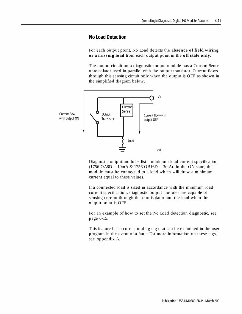
ControlLogix Diagnostic Digital I/O Module Features 4-21
No Load Detection
For each output point, No Load detects the absence of field wiring or a missing load from each output point in the off state only.
The output circuit on a diagnostic output module has a Current Sense optoisolator used in parallel with the output transistor. Current flows through this sensing circuit only when the output is OFF, as shown in the simplified diagram below.
Diagnostic output modules list a minimum load current specification (1756-OA8D = 10mA & 1756-OB16D = 3mA). In the ON-state, the module must be connected to a load which will draw a minimum current equal to these values.
If a connected load is sized in accordance with the minimum load current specification, diagnostic output modules are capable of sensing current through the optoisolator and the load when the output point is OFF.
For an example of how to set the No Load detection diagnostic, seepage 6-15.
This feature has a corresponding tag that can be examined in the user program in the event of a fault. For more information on these tags, see Appendix A.
Current Sense
Load
V+
41681
Output Transistor
Current flow with output OFF
Current flow with output ON
Publication 1756-UM058C-EN-P - March 2001
4-22 ControlLogix Diagnostic Digital I/O Module Features
Field Side Output Verification
Field Side Output Verification informs the user that logic side instructions that the module consumes are accurately represented on the power side of a switching device. In other words, for each output point, this feature confirms that the output is ON when it is commanded to be ON.
The diagnostic output module can tell a controller that it received a command and whether or not the field-side device connected to the module has executed the command. For example, in applications that need to verify that the module has accurately followed the processor’s instructions, the module samples the field side state and compares it to the system side state.
This feature has a corresponding tag that can be examined in the user program in the event of a fault. For more information on these tags, see Appendix A.
If an output cannot be verified, a point level fault is sent to the controller. For an example of how to enable the Output Verify diagnostic, see page 6-15.
Pulse Test
Pulse Test is a feature found on diagnostic output modules that can verify output-circuit functionality without actually changing the state of the output load device. A short pulse is sent to the targeted output circuit. The circuit should respond as it would if a real change-of-state command was issued, but the load device does not transition.
TIP Consider the following when using the Pulse Test:
• Only use the test when the output state does not transition for long periods of time. Normal diagnostics will catch faults if the outputs are transitioning regularly.
• When first performing the pulse test, it is recommended that you verify the load will not transition. You should be at the actual load while the test is performed.
Publication 1756-UM058C-EN-P - March 2001
ControlLogix Diagnostic Digital I/O Module Features 4-23
The Pulse Test can be used to perform a preemptive diagnosis of possible future module conditions. For example, you can use Pulse Test to:
• detect a blown fuse before it happens.
The Blown Fuse diagnostic (see page 4-20 for a complete explanation of fusing) can only be used when an output module is in the ON state. But it would useful to be made aware when operating conditions for a module may cause a blown fuse.
If you perform a pulse test on the module while the output is in the OFF state, the output point is commanded to be ON briefly, as described above. Although no diagnostic bits are set in the output data echo, the pulse test will report a failure because conditions when the point is ON indicate a blown fuse condition may occur (see pages 4-12 & 4-13).
• detect a No Load condition with an output ON.
The No Load diagnostic (see page 4-21 for a complete explanation) can only detect a fault (i.e. set the No Load bit) when an output point is in the OFF state. But you may find it useful to be made aware when operating conditions for that point may reveal a potential No Load condition.
If you perform a pulse test on an output point while it is in the ON state, the output point is commanded to be OFF briefly, as described on page 4-22. The pulse test will report a failure because conditions when the point is OFF indicate the possible absence of a field device; in this case, though, the No Load bit will not be set (see pages 4-12 & 4-13).
Pulse Test is a service that needs to be executed from an RSLogix 5000 program or the module properties page, using the pulse test tab and should be verified with your load to make sure that there are no false transitions.
For an example of how to perform a Pulse Test using ladder logic, see page B-13.
IMPORTANT The Pulse Test does not guarantee a fuse will blow when the output point turns on. It merely indicates this condition is possible.
IMPORTANT The Pulse Test does not guarantee the absence of a load. It merely indicates this condition is possible.
Publication 1756-UM058C-EN-P - March 2001
4-24 ControlLogix Diagnostic Digital I/O Module Features
Point Level Electronic Fusing
Diagnostic output modules use electronic fusing to protect output points from the surge of too much current through that point on the module. If too much current begins to flow through a point, the fuse is tripped and a point level fault is sent to the controller.
Reset an electronic fuse through RSLogix 5000 configuration software or through ladder logic running on a controller. This feature has a corresponding tag that can be examined in the user program in the event of a fault. For more information on these tags, see Appendix A.
For an example of how to reset an electronic fuse in RSLogix 5000, see page 6-22. For an example of how to reset an electronic fuse using a ladder logic program, see page B-13.
Field Power Loss Detection
This feature is used when field power to the module is lost or zero cross cannot be detected. A point level fault is sent to the controller to identify the exact point faulted.
This feature has a corresponding tag that can be examined in the user program in the event of a fault. For more information on these tags, see Appendix A.
For an example of how to enable the Field Power Loss detection diagnostic, see page 6-14.
IMPORTANT Electronic fuses are also reset through a software reset or when the output module is power cycled.
IMPORTANT Only enable Field Power Loss detection for points that are in use. If this feature is enabled for points that are not in use, you will receive faults for those points during operation.
Publication 1756-UM058C-EN-P - March 2001
ControlLogix Diagnostic Digital I/O Module Features 4-25
Diagnostic Change of State for Output Modules
Using the Diagnostic Change of State feature, a diagnostic output module sends new data to the owner controller when one of three events occurs:
• Requested Packet Interval - user-defined interval for scheduled updates during normal module operation
• Receipt of Output Data - an output module echoes data back to the owner controller
• Diagnostic Change of State - any change in the diagnostics for a particular output point
Unlike diagnostic input modules, this feature cannot be disabled for diagnostic output modules. If any of the three events described above occurs, the output module sends new data to the owner controller.
Fault and Status Reporting Between Input Modulesand Controllers
ControlLogix diagnostic digital input modules multicast fault/status data to any owner/ listening controllers.
All diagnostic input modules maintain a Module Fault Word, the highest level of fault reporting. Some modules also use additional words to indicate fault conditions, as shown on the next page.
The following tags can be examined in ladder logic to indicate when a fault has occurred:
• Module Fault Word - This word provides fault summary reporting. It’s tag name is Fault. This word is available on all digital input modules.
• Field Power Loss Word - This word indicates loss of field power to a group on the module. It’s tag name is FieldPwrLoss. This word is only available on 1756-IA8D.
For more information on field power loss, see page 4-16.
• Open Wire Word - This word indicates the loss of a wire from a point on the module. It’s tag name is OpenWire.
For more information on open wire, see page 4-15.
Publication 1756-UM058C-EN-P - March 2001
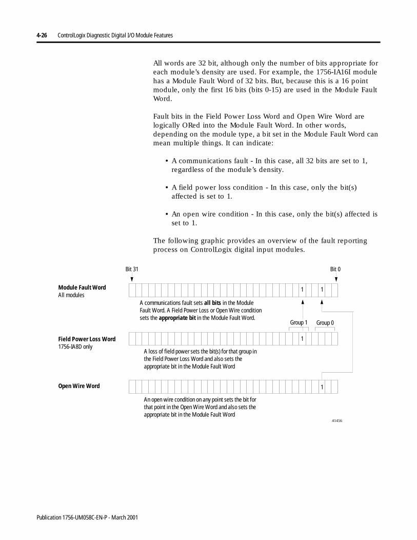
4-26 ControlLogix Diagnostic Digital I/O Module Features
All words are 32 bit, although only the number of bits appropriate for each module’s density are used. For example, the 1756-IA16I module has a Module Fault Word of 32 bits. But, because this is a 16 point module, only the first 16 bits (bits 0-15) are used in the Module Fault Word.
Fault bits in the Field Power Loss Word and Open Wire Word are logically ORed into the Module Fault Word. In other words, depending on the module type, a bit set in the Module Fault Word can mean multiple things. It can indicate:
• A communications fault - In this case, all 32 bits are set to 1, regardless of the module’s density.
• A field power loss condition - In this case, only the bit(s) affected is set to 1.
• An open wire condition - In this case, only the bit(s) affected is set to 1.
The following graphic provides an overview of the fault reporting process on ControlLogix digital input modules.
Module Fault WordAll modules
Field Power Loss Word1756-IA8D only
Open Wire Word
41456
Bit 31 Bit 0
An open wire condition on any point sets the bit for that point in the Open Wire Word and also sets the appropriate bit in the Module Fault Word
A loss of field power sets the bit(s) for that group in the Field Power Loss Word and also sets the appropriate bit in the Module Fault Word
A communications fault sets all bits in the Module Fault Word. A Field Power Loss or Open Wire condition sets the appropriate bit in the Module Fault Word.
1
1
1
1
Group 0Group 1
Publication 1756-UM058C-EN-P - March 2001
ControlLogix Diagnostic Digital I/O Module Features 4-27
Fault and Status Reporting Between Output Modulesand Controller
ControlLogix diagnostic digital output modules multicast fault/status data to any owner/listening controllers.
All output modules maintain a Module Fault Word, the highest level of fault reporting. Some modules also use additional words to indicate fault conditions, as shown on the next page.
The following tags can be examined in ladder logic to indicate when a fault has occurred:
• Module Fault Word - This word provides fault summary reporting. It’s tag name is Fault. This word is available on all digital output modules.
• Fuse Blown Word - This word indicates a point/group fuse blown on the module. It’s tag name is FuseBlown.
For more information on fusing, see page 4-20.
• Field Power Loss Word - This word indicates a loss of field power to a point on the module. It’s tag name is FieldPwrLoss. This word is only available on 1756-OA8D module.
For more information on field power loss, see page 4-16.
• No Load Word - This word indicates a loss of a load from a point on the module. It’s tag name is NoLoad.
For more information on no load conditions, see page 4-21.
• Output Verify Word - This word indicates when an output is not performing as commanded by the owner controller. It’s tag name is OutputVerify.
For more information on output verify, see page 4-22.
All words are 32 bit, although only the number of bits appropriate for each module’s density are used. For example, the 1756-OB8 module has a Module Fault Word of 32 bits. But, because the module is an 8 point module, only the first 8 bits (bits0-7) are used in the Module Fault Word.
Publication 1756-UM058C-EN-P - March 2001
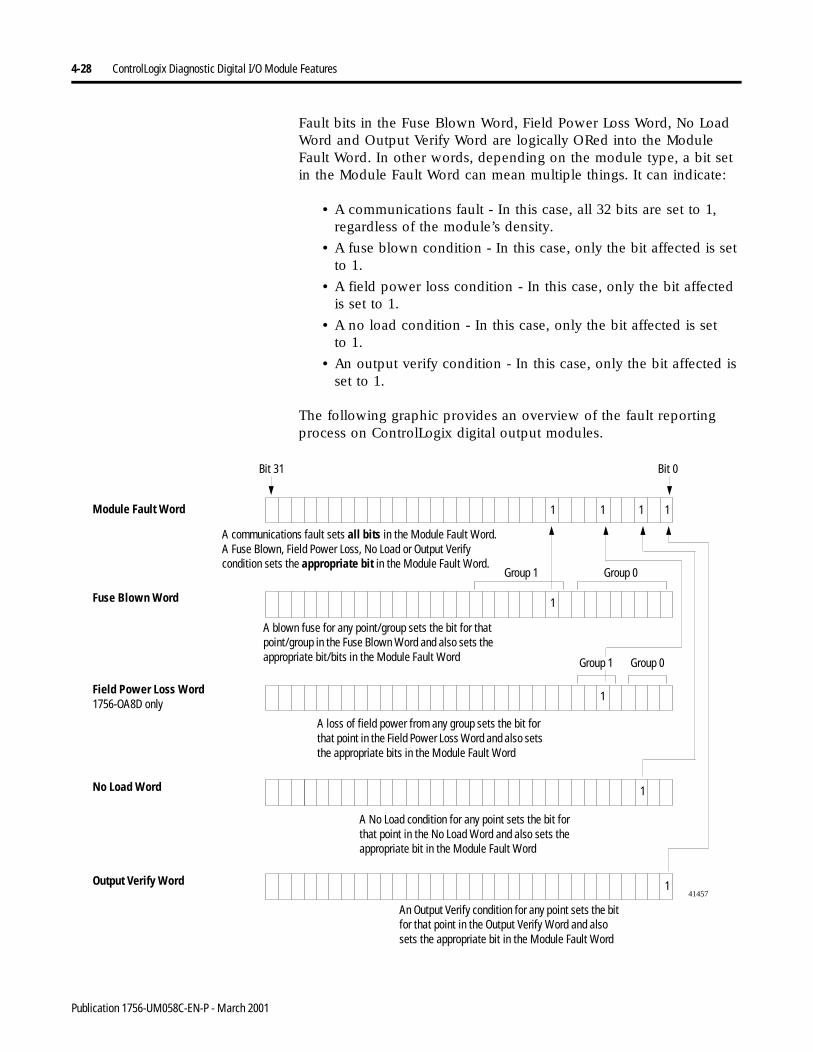
4-28 ControlLogix Diagnostic Digital I/O Module Features
Fault bits in the Fuse Blown Word, Field Power Loss Word, No Load Word and Output Verify Word are logically ORed into the Module Fault Word. In other words, depending on the module type, a bit set in the Module Fault Word can mean multiple things. It can indicate:
• A communications fault - In this case, all 32 bits are set to 1, regardless of the module’s density.
• A fuse blown condition - In this case, only the bit affected is set to 1.
• A field power loss condition - In this case, only the bit affected is set to 1.
• A no load condition - In this case, only the bit affected is setto 1.
• An output verify condition - In this case, only the bit affected is set to 1.
The following graphic provides an overview of the fault reporting process on ControlLogix digital output modules.
Module Fault Word
Fuse Blown Word
Field Power Loss Word1756-OA8D only
41457
Bit 31 Bit 0
A No Load condition for any point sets the bit for that point in the No Load Word and also sets the appropriate bit in the Module Fault Word
A blown fuse for any point/group sets the bit for that point/group in the Fuse Blown Word and also sets the appropriate bit/bits in the Module Fault Word
A communications fault sets all bits in the Module Fault Word. A Fuse Blown, Field Power Loss, No Load or Output Verify condition sets the appropriate bit in the Module Fault Word.
No Load Word
Output Verify Word
A loss of field power from any group sets the bit for that point in the Field Power Loss Word and also sets the appropriate bits in the Module Fault Word
An Output Verify condition for any point sets the bit for that point in the Output Verify Word and also sets the appropriate bit in the Module Fault Word
1
Group 0
1
Group 0Group 1
1
1
1
1
Group 1
1
1
Publication 1756-UM058C-EN-P - March 2001
ControlLogix Diagnostic Digital I/O Module Features 4-29
Chapter Summary andWhat’s Next
In this chapter you learned about:
• determining input module compatibility
• determining output module compatibility
• using features common to ControlLogix diagnostic digital I/O modules
• using features specific to ControlLogix diagnostic digital input modules
• using features specific to ControlLogix diagnostic digital output modules
Move to Chapter 5, Installing the ControlLogix I/O Module.
Publication 1756-UM058C-EN-P - March 2001

4-30 ControlLogix Diagnostic Digital I/O Module Features
Notes:
Publication 1756-UM058C-EN-P - March 2001
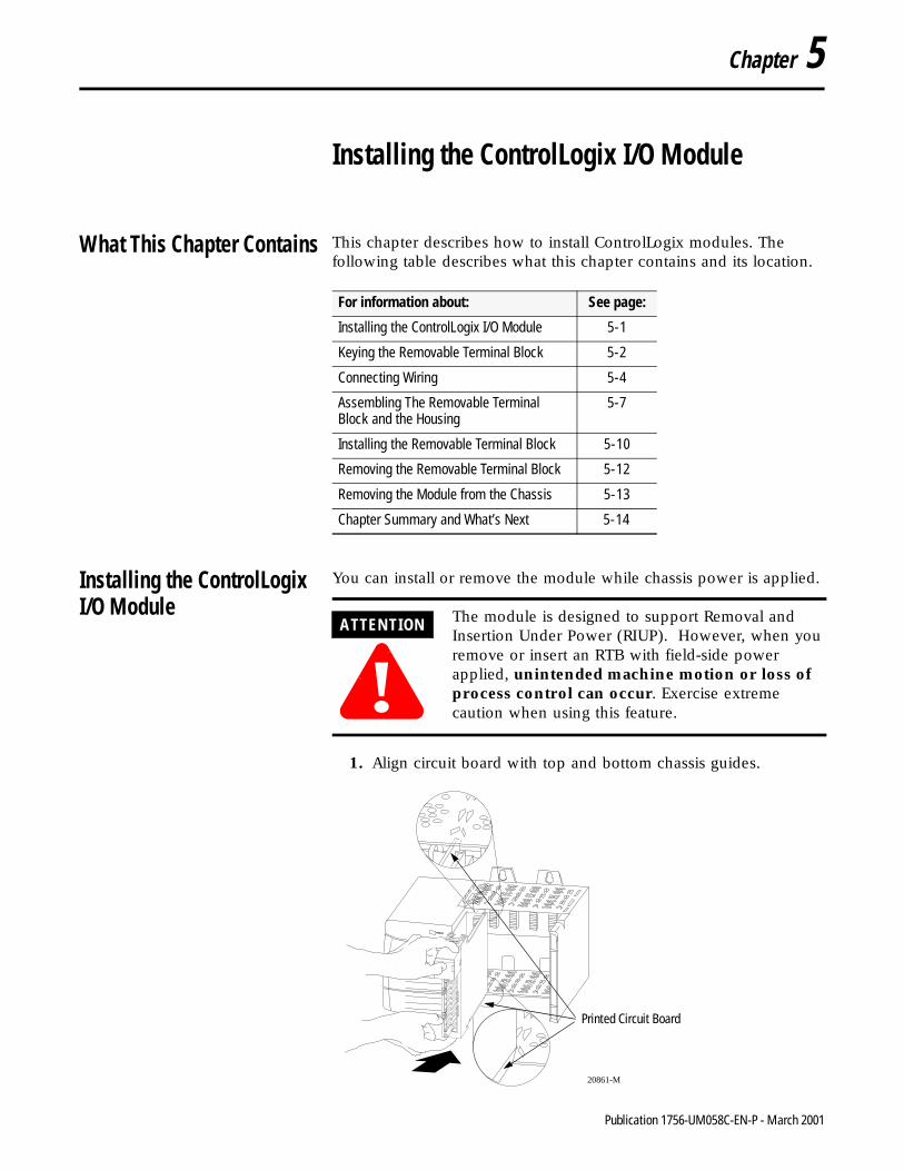
Chapter 5
Installing the ControlLogix I/O Module
What This Chapter Contains This chapter describes how to install ControlLogix modules. The following table describes what this chapter contains and its location.
Installing the ControlLogixI/O Module
You can install or remove the module while chassis power is applied.
1. Align circuit board with top and bottom chassis guides.
For information about: See page:
Installing the ControlLogix I/O Module 5-1
Keying the Removable Terminal Block 5-2
Connecting Wiring 5-4
Assembling The Removable Terminal Block and the Housing
5-7
Installing the Removable Terminal Block 5-10
Removing the Removable Terminal Block 5-12
Removing the Module from the Chassis 5-13
Chapter Summary and What’s Next 5-14
ATTENTION
!The module is designed to support Removal and Insertion Under Power (RIUP). However, when you remove or insert an RTB with field-side power applied, unintended machine motion or loss of process control can occur. Exercise extreme caution when using this feature.
20861-M
Printed Circuit Board
1 Publication 1756-UM058C-EN-P - March 2001
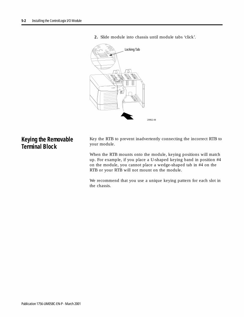
5-2 Installing the ControlLogix I/O Module
2. Slide module into chassis until module tabs ‘click’.
Keying the RemovableTerminal Block
Key the RTB to prevent inadvertently connecting the incorrect RTB toyour module.
When the RTB mounts onto the module, keying positions will match up. For example, if you place a U-shaped keying band in position #4 on the module, you cannot place a wedge-shaped tab in #4 on the RTB or your RTB will not mount on the module.
We recommend that you use a unique keying pattern for each slot inthe chassis.
20862-M
Locking Tab
Publication 1756-UM058C-EN-P - March 2001
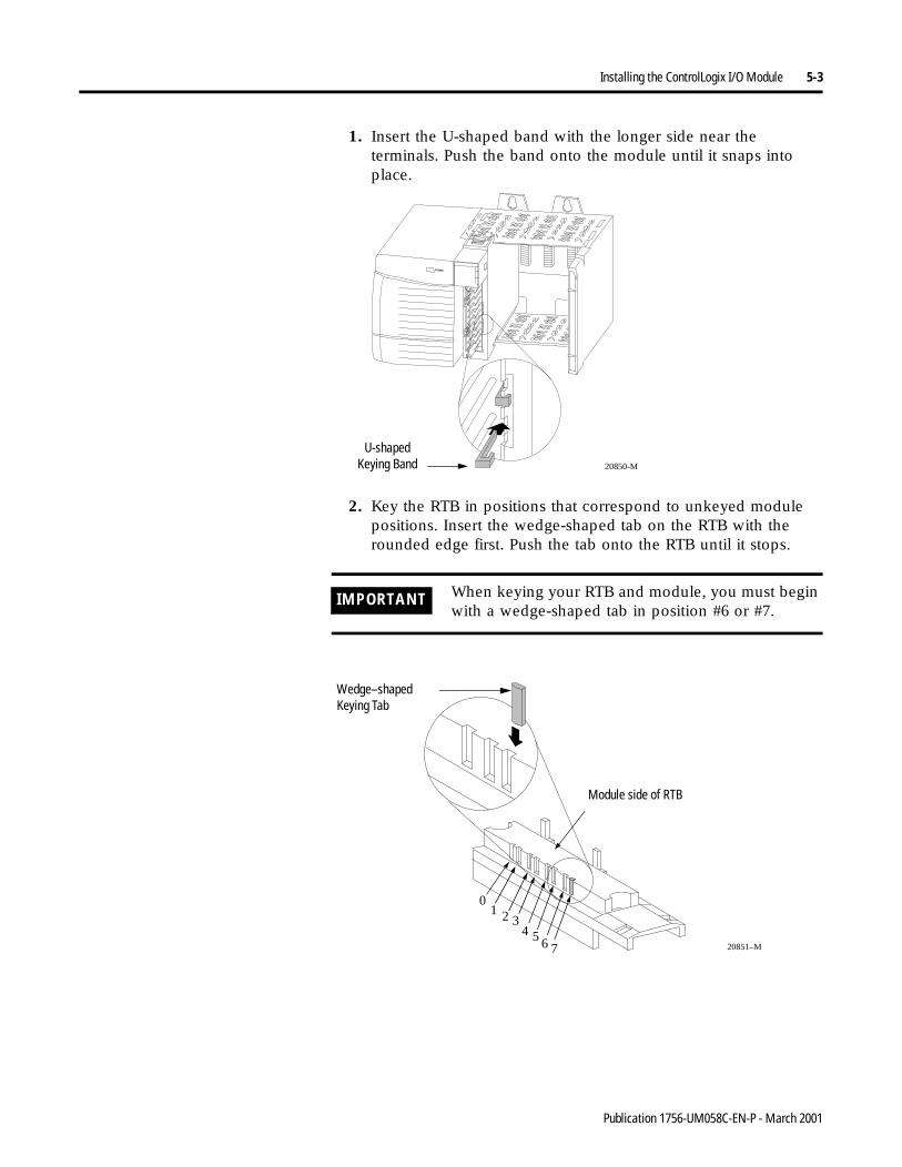
Installing the ControlLogix I/O Module 5-3
1. Insert the U-shaped band with the longer side near the terminals. Push the band onto the module until it snaps into place.
2. Key the RTB in positions that correspond to unkeyed module positions. Insert the wedge-shaped tab on the RTB with the rounded edge first. Push the tab onto the RTB until it stops.
IMPORTANT When keying your RTB and module, you must begin with a wedge-shaped tab in position #6 or #7.
20850-M
U-shaped Keying Band
20851–M
1 20
34 5 6 7
Module side of RTB
Wedge–shaped Keying Tab
Publication 1756-UM058C-EN-P - March 2001
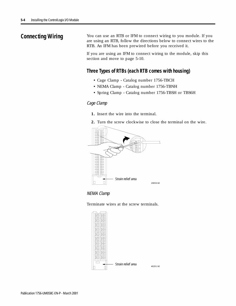
5-4 Installing the ControlLogix I/O Module
Connecting Wiring You can use an RTB or IFM to connect wiring to you module. If you are using an RTB, follow the directions below to connect wires to the RTB. An IFM has been prewired before you received it.
If you are using an IFM to connect wiring to the module, skip this section and move to page 5-10.
Three Types of RTBs (each RTB comes with housing)
• Cage Clamp - Catalog number 1756-TBCH
• NEMA Clamp - Catalog number 1756-TBNH
• Spring Clamp - Catalog number 1756-TBSH or TBS6H
Cage Clamp
1. Insert the wire into the terminal.
2. Turn the screw clockwise to close the terminal on the wire.
NEMA Clamp
Terminate wires at the screw terminals.
20859-M
Strain relief area
40201-MStrain relief area
Publication 1756-UM058C-EN-P - March 2001
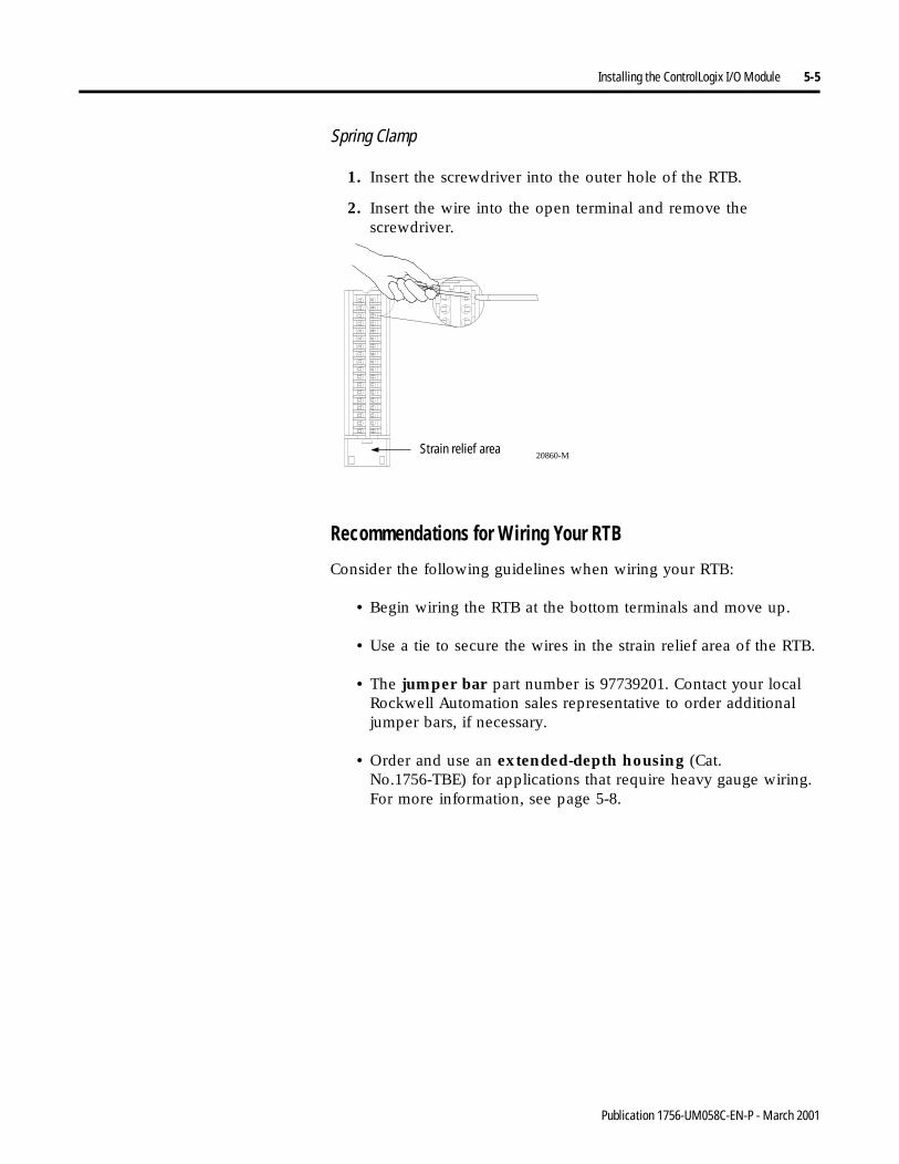
Installing the ControlLogix I/O Module 5-5
Spring Clamp
1. Insert the screwdriver into the outer hole of the RTB.
2. Insert the wire into the open terminal and remove the screwdriver.
Recommendations for Wiring Your RTB
Consider the following guidelines when wiring your RTB:
• Begin wiring the RTB at the bottom terminals and move up.
• Use a tie to secure the wires in the strain relief area of the RTB.
• The jumper bar part number is 97739201. Contact your local Rockwell Automation sales representative to order additional jumper bars, if necessary.
• Order and use an extended-depth housing (Cat. No.1756-TBE) for applications that require heavy gauge wiring. For more information, see page 5-8.
20860-MStrain relief area
Publication 1756-UM058C-EN-P - March 2001
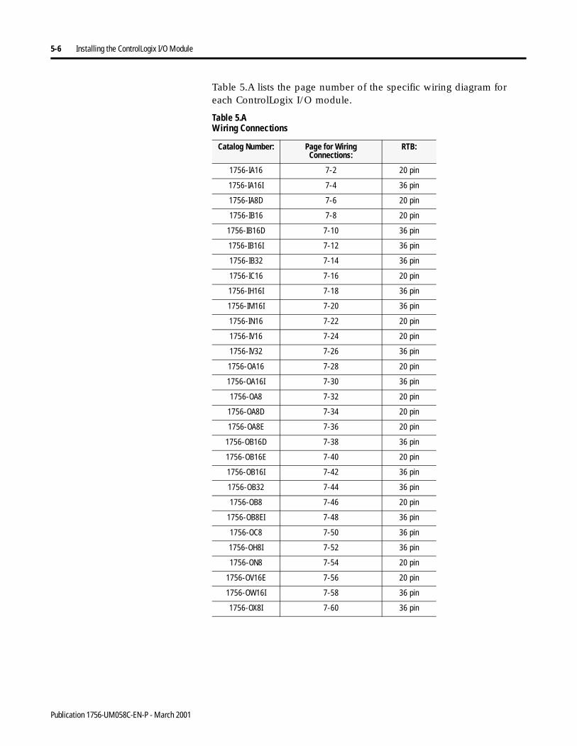
5-6 Installing the ControlLogix I/O Module
Table 5.A lists the page number of the specific wiring diagram for each ControlLogix I/O module.
Table 5.A Wiring Connections
Catalog Number: Page for Wiring Connections:
RTB:
1756-IA16 7-2 20 pin
1756-IA16I 7-4 36 pin
1756-IA8D 7-6 20 pin
1756-IB16 7-8 20 pin
1756-IB16D 7-10 36 pin
1756-IB16I 7-12 36 pin
1756-IB32 7-14 36 pin
1756-IC16 7-16 20 pin
1756-IH16I 7-18 36 pin
1756-IM16I 7-20 36 pin
1756-IN16 7-22 20 pin
1756-IV16 7-24 20 pin
1756-IV32 7-26 36 pin
1756-OA16 7-28 20 pin
1756-OA16I 7-30 36 pin
1756-OA8 7-32 20 pin
1756-OA8D 7-34 20 pin
1756-OA8E 7-36 20 pin
1756-OB16D 7-38 36 pin
1756-OB16E 7-40 20 pin
1756-OB16I 7-42 36 pin
1756-OB32 7-44 36 pin
1756-OB8 7-46 20 pin
1756-OB8EI 7-48 36 pin
1756-OC8 7-50 36 pin
1756-OH8I 7-52 36 pin
1756-ON8 7-54 20 pin
1756-OV16E 7-56 20 pin
1756-OW16I 7-58 36 pin
1756-OX8I 7-60 36 pin
Publication 1756-UM058C-EN-P - March 2001
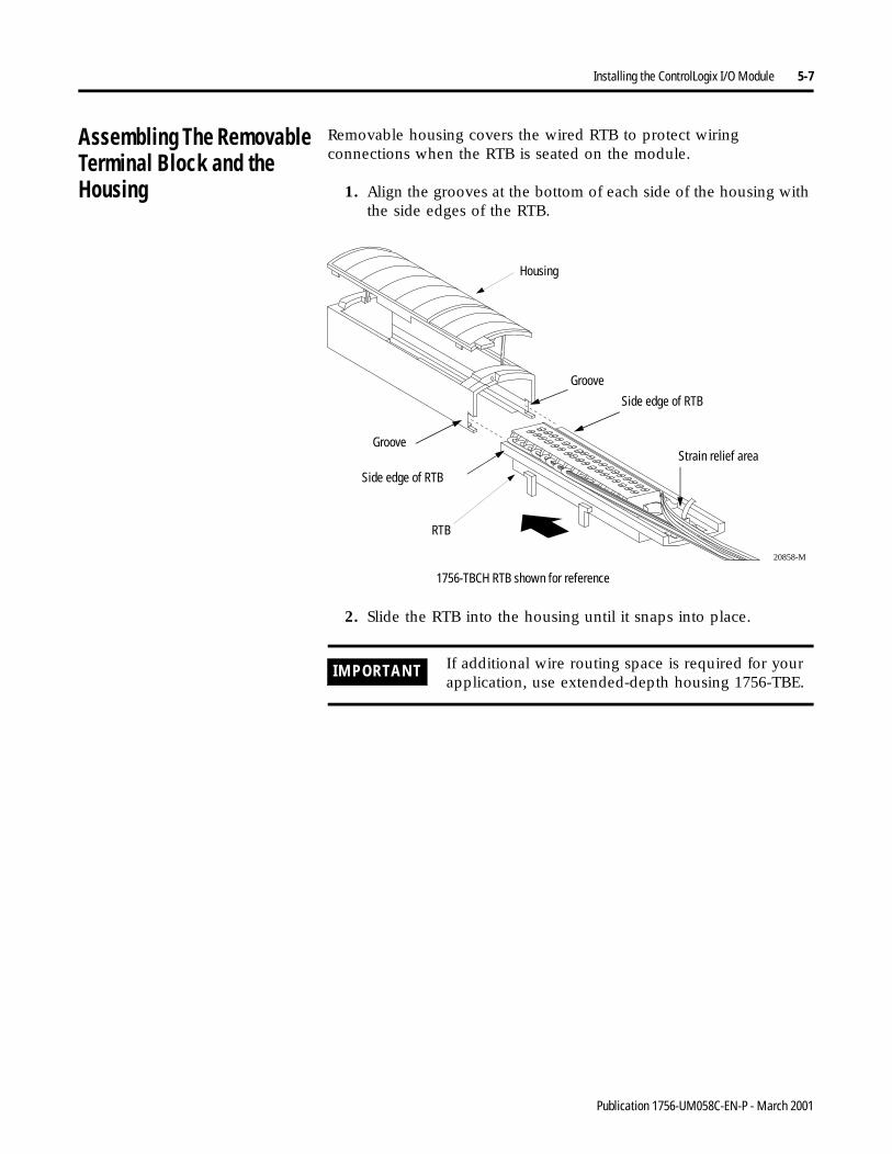
Installing the ControlLogix I/O Module 5-7
Assembling The Removable Terminal Block and the Housing
Removable housing covers the wired RTB to protect wiring connections when the RTB is seated on the module.
1. Align the grooves at the bottom of each side of the housing with the side edges of the RTB.
2. Slide the RTB into the housing until it snaps into place.
20858-M
Housing
RTB
Groove
Groove
Side edge of RTB
Side edge of RTB
1756-TBCH RTB shown for reference
Strain relief area
IMPORTANT If additional wire routing space is required for your application, use extended-depth housing 1756-TBE.
Publication 1756-UM058C-EN-P - March 2001
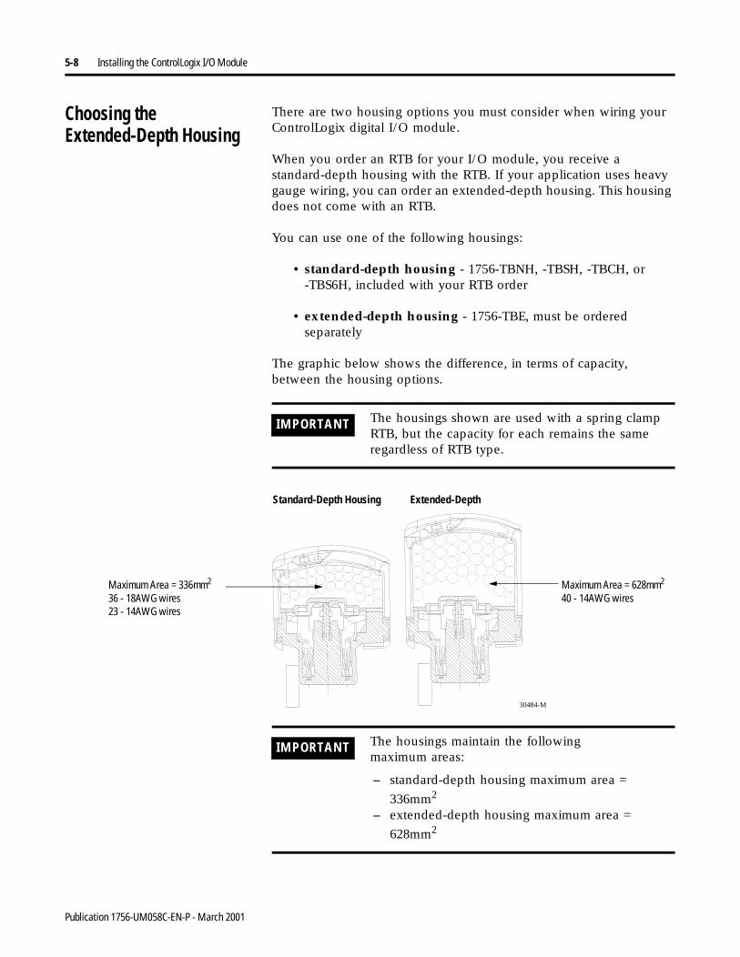
5-8 Installing the ControlLogix I/O Module
Choosing the Extended-Depth Housing
There are two housing options you must consider when wiring your ControlLogix digital I/O module.
When you order an RTB for your I/O module, you receive a standard-depth housing with the RTB. If your application uses heavy gauge wiring, you can order an extended-depth housing. This housing does not come with an RTB.
You can use one of the following housings:
• standard-depth housing - 1756-TBNH, -TBSH, -TBCH, or -TBS6H, included with your RTB order
• extended-depth housing - 1756-TBE, must be ordered separately
The graphic below shows the difference, in terms of capacity, between the housing options.
IMPORTANT The housings shown are used with a spring clamp RTB, but the capacity for each remains the same regardless of RTB type.
Standard-Depth Housing Extended-Depth
30484-M
Maximum Area = 336mm2
36 - 18AWG wires23 - 14AWG wires
Maximum Area = 628mm2
40 - 14AWG wires
IMPORTANT The housings maintain the followingmaximum areas:
– standard-depth housing maximum area =
336mm2
– extended-depth housing maximum area =
628mm2
Publication 1756-UM058C-EN-P - March 2001
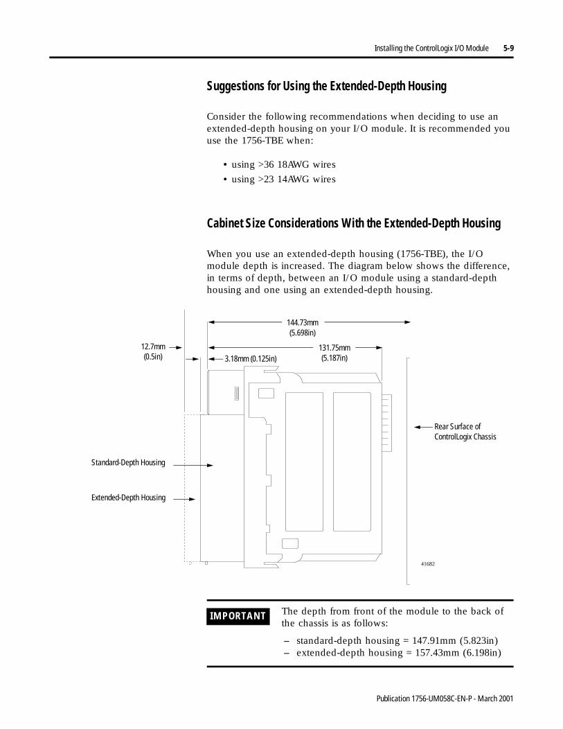
Installing the ControlLogix I/O Module 5-9
Suggestions for Using the Extended-Depth Housing
Consider the following recommendations when deciding to use an extended-depth housing on your I/O module. It is recommended you use the 1756-TBE when:
• using >36 18AWG wires
• using >23 14AWG wires
Cabinet Size Considerations With the Extended-Depth Housing
When you use an extended-depth housing (1756-TBE), the I/O module depth is increased. The diagram below shows the difference, in terms of depth, between an I/O module using a standard-depth housing and one using an extended-depth housing.
41682
Standard-Depth Housing
Extended-Depth Housing
144.73mm(5.698in)
Rear Surface of ControlLogix Chassis
131.75mm(5.187in)3.18mm (0.125in)
12.7mm(0.5in)
IMPORTANT The depth from front of the module to the back of the chassis is as follows:
– standard-depth housing = 147.91mm (5.823in)– extended-depth housing = 157.43mm (6.198in)
Publication 1756-UM058C-EN-P - March 2001
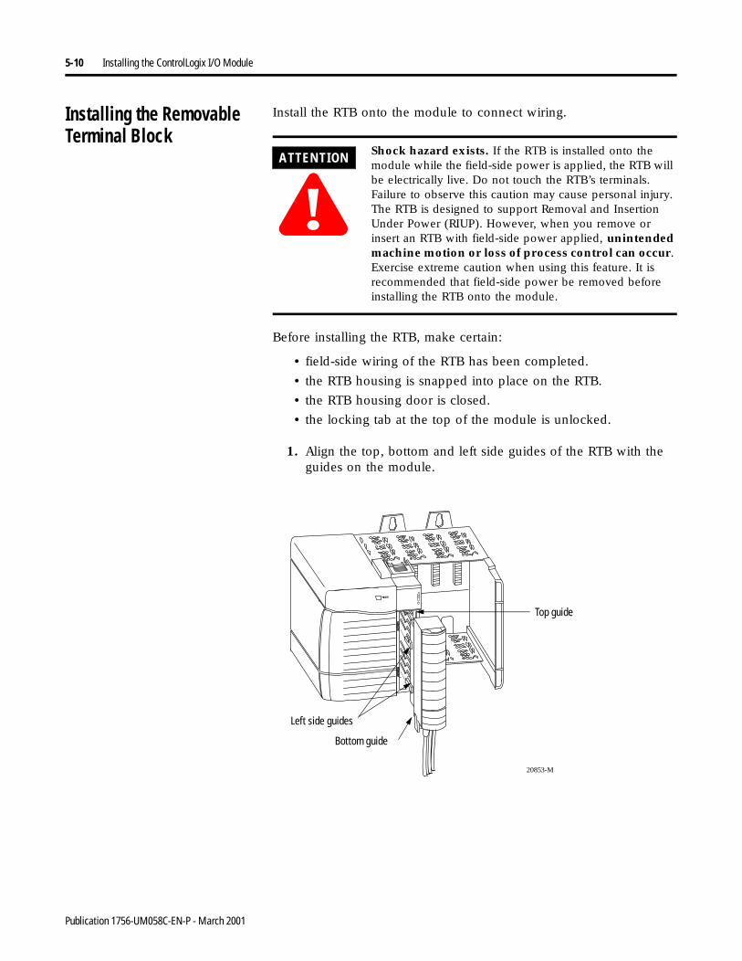
5-10 Installing the ControlLogix I/O Module
Installing the Removable Terminal Block
Install the RTB onto the module to connect wiring.
Before installing the RTB, make certain:
• field-side wiring of the RTB has been completed.
• the RTB housing is snapped into place on the RTB.
• the RTB housing door is closed.
• the locking tab at the top of the module is unlocked.
1. Align the top, bottom and left side guides of the RTB with the guides on the module.
ATTENTION
!Shock hazard exists. If the RTB is installed onto the module while the field-side power is applied, the RTB will be electrically live. Do not touch the RTB’s terminals. Failure to observe this caution may cause personal injury.The RTB is designed to support Removal and Insertion Under Power (RIUP). However, when you remove or insert an RTB with field-side power applied, unintended machine motion or loss of process control can occur. Exercise extreme caution when using this feature. It is recommended that field-side power be removed before installing the RTB onto the module.
20853-M
Top guide
Bottom guide
Left side guides
Publication 1756-UM058C-EN-P - March 2001
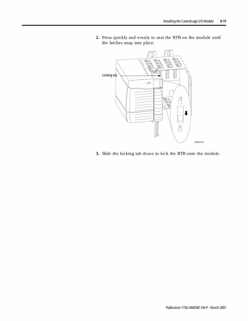
Installing the ControlLogix I/O Module 5-11
2. Press quickly and evenly to seat the RTB on the module until the latches snap into place.
3. Slide the locking tab down to lock the RTB onto the module.
20854-M
Locking tab
Publication 1756-UM058C-EN-P - March 2001
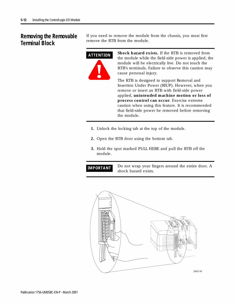
5-12 Installing the ControlLogix I/O Module
Removing the Removable Terminal Block
If you need to remove the module from the chassis, you must first remove the RTB from the module.
1. Unlock the locking tab at the top of the module.
2. Open the RTB door using the bottom tab.
3. Hold the spot marked PULL HERE and pull the RTB off the module.
ATTENTION
!Shock hazard exists. If the RTB is removed from the module while the field-side power is applied, the module will be electrically live. Do not touch the RTB’s terminals. Failure to observe this caution may cause personal injury.
The RTB is designed to support Removal and Insertion Under Power (RIUP). However, when you remove or insert an RTB with field-side power applied, unintended machine motion or loss of process control can occur. Exercise extreme caution when using this feature. It is recommended that field-side power be removed before removing the module.
IMPORTANT Do not wrap your fingers around the entire door. A shock hazard exists.
20855-M
Publication 1756-UM058C-EN-P - March 2001
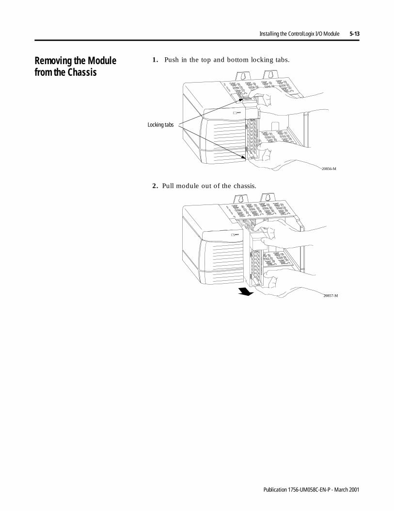
Installing the ControlLogix I/O Module 5-13
Removing the Modulefrom the Chassis
1. Push in the top and bottom locking tabs.
2. Pull module out of the chassis.
20856-M
Locking tabs
20857-M
Publication 1756-UM058C-EN-P - March 2001
5-14 Installing the ControlLogix I/O Module
Chapter Summary andWhat’s Next
In this chapter you learned about:
• installing the module.
• keying the removable terminal block and the interface module.
• connecting wiring.
• assembling the removable terminal block and the housing.
• installing the removable terminal block or interface module onto the module.
• removing the removable terminal block from the module.
• removing the module from the chassis.
Move on to Chapter 6, Configuring Your ControlLogix Digital I/O Modules.
Publication 1756-UM058C-EN-P - March 2001
Chapter 6
Configuring Your ControlLogixDigital I/O Modules
What This Chapter Contains This chapter describes why you must configure your ControlLogix digital I/O modules and how to configure them for use in the ControlLogix system.
For information about: See page:
Configuring Your I/O Module 6-2
Overview of the Configuration Process 6-2
Creating a New Module 6-4
Using the Default Configuration 6-10
Altering the Default Configuration 6-10
Configuring a Standard Input Module 6-12
Configuring a Standard Output Module 6-13
Configuring a Diagnostic Input Module 6-14
Configuring a Diagnostic Output Module 6-15
Editing Configuration 6-16
Reconfiguring Module Parameters in Remote Run Mode
6-17
Reconfiguring Module Parameters in Program Mode
6-18
Configuring I/O Modules in a Remote Chassis
6-19
Input Online Services 6-21
Output Online Services 6-22
Viewing and Changing Module Tags 6-23
Chapter Summary and What’s Next 6-24
1 Publication 1756-UM058C-EN-P - March 2001
6-2 Configuring Your ControlLogix Digital I/O Modules
Configuring Your I/O Module
You must configure your module upon installation. The module will not work until it has been configured.
RSLogix 5000 Configuration Software
Use RSLogix 5000 software to set configuration for your ControlLogix digital I/O module. You have the option of accepting default configuration for your module or writing point level configuration specific to your application.
Both options are explained in detail, including views of software screens, in this chapter.
Overview of theConfiguration Process
When you use the RSLogix 5000 software to configure a ControlLogix digital I/O module, you must perform the following steps:
1. Create a new module.
2. Accept the default configuration or change it to specific configuration for the module.
3. Edit configuration for a module when changes are needed.
IMPORTANT This chapter focuses on configuring I/O modules in a local chassis. To configure I/O modules in a remote chassis, you must follow all the detailed procedures with two additional steps. An explanation of the additional steps is listed at the end of this chapter.
Publication 1756-UM058C-EN-P - March 2001
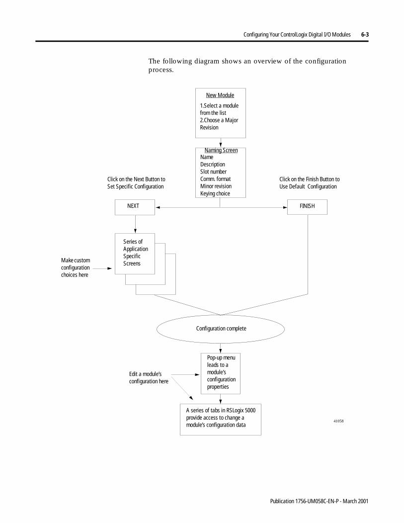
Configuring Your ControlLogix Digital I/O Modules 6-3
The following diagram shows an overview of the configuration process.
1.Select a modulefrom the list2.Choose a MajorRevision
NameDescriptionSlot numberComm. formatMinor revisionKeying choice
Series of Application Specific ScreensMake custom
configuration choices here
Pop-up menu leads to a module’s configuration properties
Edit a module’s configuration here
A series of tabs in RSLogix 5000 provide access to change a module’s configuration data
Click on the Next Button to Set Specific Configuration
Click on the Finish Button to Use Default Configuration
41058
New Module
Naming Screen
NEXT FINISH
Configuration complete
Publication 1756-UM058C-EN-P - March 2001
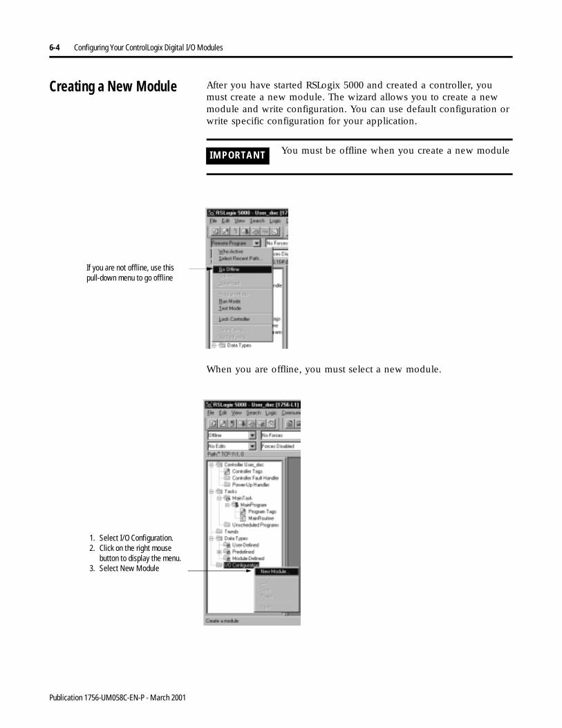
6-4 Configuring Your ControlLogix Digital I/O Modules
Creating a New Module After you have started RSLogix 5000 and created a controller, you must create a new module. The wizard allows you to create a new module and write configuration. You can use default configuration or write specific configuration for your application.
When you are offline, you must select a new module.
IMPORTANT You must be offline when you create a new module
If you are not offline, use this pull-down menu to go offline
1. Select I/O Configuration.2. Click on the right mouse
button to display the menu.3. Select New Module
Publication 1756-UM058C-EN-P - March 2001
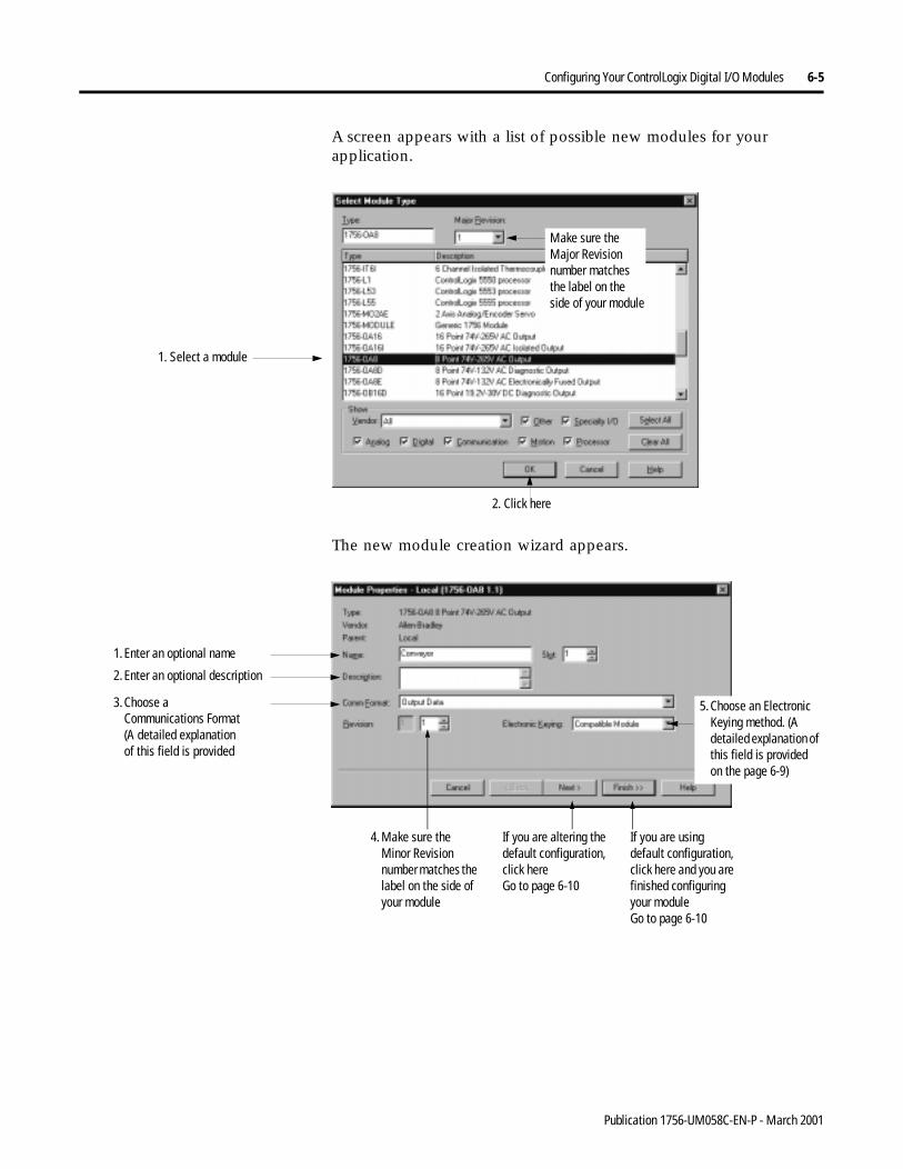
Configuring Your ControlLogix Digital I/O Modules 6-5
A screen appears with a list of possible new modules for your application.
The new module creation wizard appears.
1. Select a module
Make sure the Major Revision number matches the label on the side of your module
2. Click here
1. Enter an optional name
2. Enter an optional description
3. Choose a Communications Format (A detailed explanation of this field is provided
5. Choose an Electronic Keying method. (A detailed explanation of this field is provided on the page 6-9)
If you are using default configuration, click here and you are finished configuring your moduleGo to page 6-10
If you are altering the default configuration, click here Go to page 6-10
4. Make sure the Minor Revision number matches the label on the side of your module
Publication 1756-UM058C-EN-P - March 2001
6-6 Configuring Your ControlLogix Digital I/O Modules
Communications Format
The communications format determines what type of configuration options are made available, what type of data is transferred between the module and its owner controller, and what tags are generated when configuration is complete.
This feature also defines the connection between the controller writing the configuration and the module itself. The number and type of choices varies depending on which input module you are using and whether it is in a local or remote chassis.
Input Module Formats
The following are possible Communications Format choices forinput modules:
• input data - module returns only general fault and input data
• CST timestamped input data - module returns input data with the value of the system clock (from its local chassis) when the input data changed
• Full diagnostic input data - module returns input data, the value of the system clock (from its local chassis) when the input data changed, and diagnostic data (diagnostic modules only)
• Rack optimization - the 1756-CNB module collects all digital input words in the remote chassis and sends them to the controller as a single rack image. This connection type limits the status and diagnostic information available
These additional Communications Format choices are used by controllers that want to listen to an input module but not own it. The choices have the same definition as those above:
• Listen only - input data
• Listen only - CST timestamped input data
• Listen only - full diagnostic input data
• Listen only - rack optimization
TIP When you select a Listen-only Communications Format, only the General and Connection tabs appear when you view a module’s properties in RSLogix 5000.
Publication 1756-UM058C-EN-P - March 2001
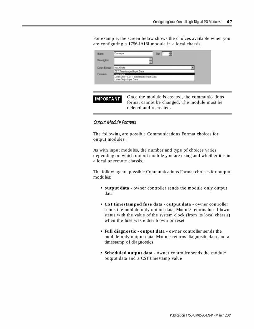
Configuring Your ControlLogix Digital I/O Modules 6-7
For example, the screen below shows the choices available when you are configuring a 1756-IA16I module in a local chassis.
Output Module Formats
The following are possible Communications Format choices foroutput modules:
As with input modules, the number and type of choices varies depending on which output module you are using and whether it is in a local or remote chassis.
The following are possible Communications Format choices for output modules:
• output data - owner controller sends the module only output data
• CST timestamped fuse data - output data - owner controller sends the module only output data. Module returns fuse blown status with the value of the system clock (from its local chassis) when the fuse was either blown or reset
• Full diagnostic - output data - owner controller sends the module only output data. Module returns diagnostic data and a timestamp of diagnostics
• Scheduled output data - owner controller sends the module output data and a CST timestamp value
IMPORTANT Once the module is created, the communications format cannot be changed. The module must be deleted and recreated.
Publication 1756-UM058C-EN-P - March 2001
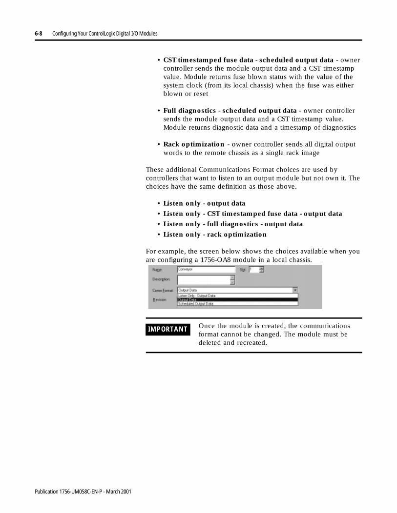
6-8 Configuring Your ControlLogix Digital I/O Modules
• CST timestamped fuse data - scheduled output data - owner controller sends the module output data and a CST timestamp value. Module returns fuse blown status with the value of the system clock (from its local chassis) when the fuse was either blown or reset
• Full diagnostics - scheduled output data - owner controller sends the module output data and a CST timestamp value. Module returns diagnostic data and a timestamp of diagnostics
• Rack optimization - owner controller sends all digital output words to the remote chassis as a single rack image
These additional Communications Format choices are used by controllers that want to listen to an output module but not own it. The choices have the same definition as those above.
• Listen only - output data
• Listen only - CST timestamped fuse data - output data
• Listen only - full diagnostics - output data
• Listen only - rack optimization
For example, the screen below shows the choices available when you are configuring a 1756-OA8 module in a local chassis.
IMPORTANT Once the module is created, the communications format cannot be changed. The module must be deleted and recreated.
Publication 1756-UM058C-EN-P - March 2001
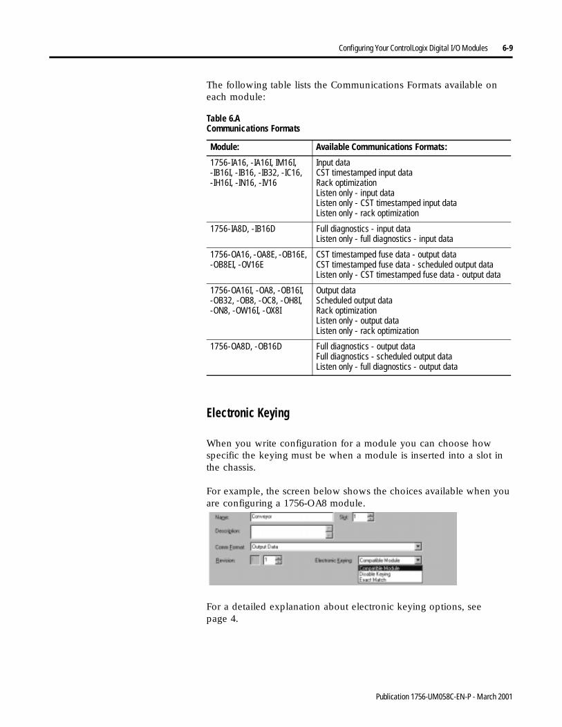
Configuring Your ControlLogix Digital I/O Modules 6-9
The following table lists the Communications Formats available on each module:
Electronic Keying
When you write configuration for a module you can choose how specific the keying must be when a module is inserted into a slot in the chassis.
For example, the screen below shows the choices available when you are configuring a 1756-OA8 module.
For a detailed explanation about electronic keying options, seepage 4.
Table 6.A Communications Formats
Module: Available Communications Formats:
1756-IA16, -IA16I, IM16I, -IB16I, -IB16, -IB32, -IC16, -IH16I, -IN16, -IV16
Input dataCST timestamped input dataRack optimizationListen only - input dataListen only - CST timestamped input dataListen only - rack optimization
1756-IA8D, -IB16D Full diagnostics - input dataListen only - full diagnostics - input data
1756-OA16, -OA8E, -OB16E, -OB8EI, -OV16E
CST timestamped fuse data - output dataCST timestamped fuse data - scheduled output dataListen only - CST timestamped fuse data - output data
1756-OA16I, -OA8, -OB16I, -OB32, -OB8, -OC8, -OH8I, -ON8, -OW16I, -OX8I
Output dataScheduled output dataRack optimizationListen only - output dataListen only - rack optimization
1756-OA8D, -OB16D Full diagnostics - output dataFull diagnostics - scheduled output dataListen only - full diagnostics - output data
Publication 1756-UM058C-EN-P - March 2001
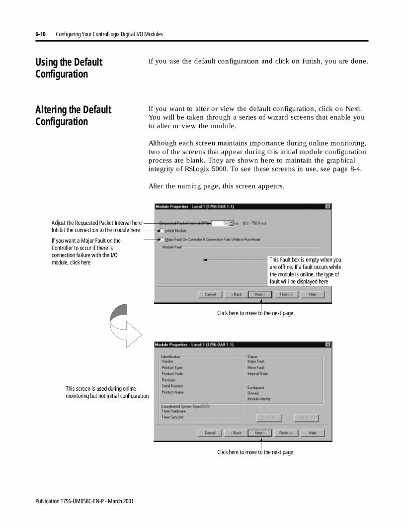
6-10 Configuring Your ControlLogix Digital I/O Modules
Using the Default Configuration
If you use the default configuration and click on Finish, you are done.
Altering the Default Configuration
If you want to alter or view the default configuration, click on Next. You will be taken through a series of wizard screens that enable you to alter or view the module.
Although each screen maintains importance during online monitoring, two of the screens that appear during this initial module configuration process are blank. They are shown here to maintain the graphical integrity of RSLogix 5000. To see these screens in use, see page 8-4.
After the naming page, this screen appears.
Click here to move to the next page
Click here to move to the next page
This screen is used during online monitoring but not initial configuration
If you want a Major Fault on the Controller to occur if there is connection failure with the I/O module, click here This Fault box is empty when you
are offline. If a fault occurs while the module is online, the type of fault will be displayed here
Inhibit the connection to the module hereAdjust the Requested Packet Interval here
Publication 1756-UM058C-EN-P - March 2001
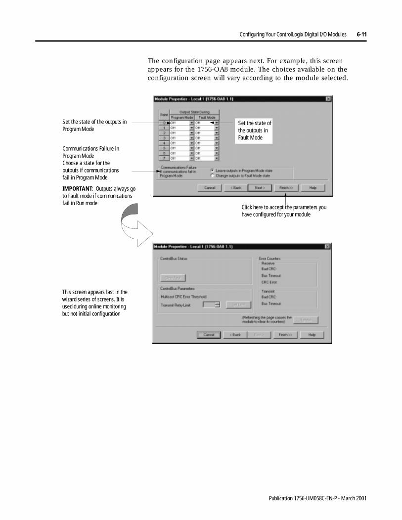
Configuring Your ControlLogix Digital I/O Modules 6-11
The configuration page appears next. For example, this screen appears for the 1756-OA8 module. The choices available on the configuration screen will vary according to the module selected.
This screen appears last in the wizard series of screens. It is used during online monitoring but not initial configuration
Set the state of the outputs inProgram Mode
Communications Failure in Program ModeChoose a state for the outputs if communications fail in Program Mode
Click here to accept the parameters you have configured for your module
Set the state of the outputs inFault Mode
IMPORTANT: Outputs always go to Fault mode if communications fail in Run mode
Publication 1756-UM058C-EN-P - March 2001
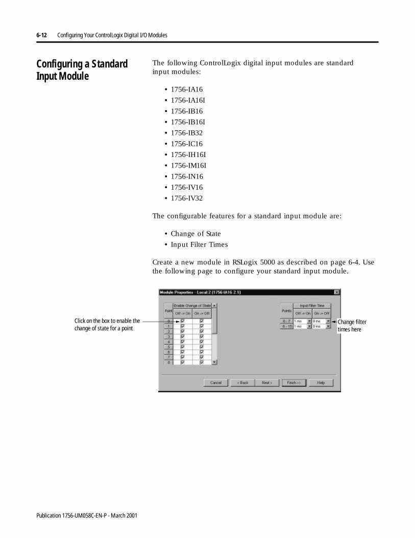
6-12 Configuring Your ControlLogix Digital I/O Modules
Configuring a StandardInput Module
The following ControlLogix digital input modules are standardinput modules:
• 1756-IA16
• 1756-IA16I
• 1756-IB16
• 1756-IB16I
• 1756-IB32
• 1756-IC16
• 1756-IH16I
• 1756-IM16I
• 1756-IN16
• 1756-IV16
• 1756-IV32
The configurable features for a standard input module are:
• Change of State
• Input Filter Times
Create a new module in RSLogix 5000 as described on page 6-4. Use the following page to configure your standard input module.
Click on the box to enable the change of state for a point
Change filter times here
Publication 1756-UM058C-EN-P - March 2001
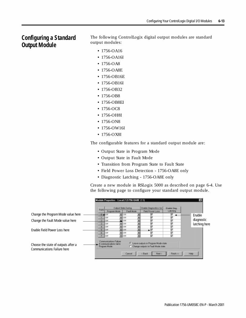
Configuring Your ControlLogix Digital I/O Modules 6-13
Configuring a StandardOutput Module
The following ControlLogix digital output modules are standard output modules:
• 1756-OA16
• 1756-OA16I
• 1756-OA8
• 1756-OA8E
• 1756-OB16E
• 1756-OB16I
• 1756-OB32
• 1756-OB8
• 1756-OB8EI
• 1756-OC8
• 1756-OH8I
• 1756-ON8
• 1756-OW16I
• 1756-OX8I
The configurable features for a standard output module are:
• Output State in Program Mode
• Output State in Fault Mode
• Transition from Program State to Fault State
• Field Power Loss Detection - 1756-OA8E only
• Diagnostic Latching - 1756-OA8E only
Create a new module in RSLogix 5000 as described on page 6-4. Use the following page to configure your standard output module.
Change the Program Mode value here Enable diagnostic latching here
Change the Fault Mode value here
Enable Field Power Loss here
Choose the state of outputs after a Communications Failure here
Publication 1756-UM058C-EN-P - March 2001

6-14 Configuring Your ControlLogix Digital I/O Modules
Configuring a DiagnosticInput Module
The following ControlLogix digital input modules are diagnosticinput modules:
• 1756-IA8D
• 1756-IB16D
The configurable features for a diagnostic input module are:
• Input Change of State
• Input Filter Times
• Open Wire Detection
• Field Power Loss Detection
• Diagnostic Latching
• Diagnostic Change of State
Create a new module in RSLogix 5000 as described on page 6-4. Use the following pages to configure your diagnostic input module.
One diagnostic, Reset Latched Diagnostics, is not used when writing configuration but is typically accessed during online monitoring. For more information on how to reset Latched Diagnostics, see page 6-21.
Enable Field Power Loss here
Enable Change of State here Change filter times here.Enable Open Wire here
Enable Diagnostic Latching here
Enable Change of State for Diagnostic Transitions here
Publication 1756-UM058C-EN-P - March 2001
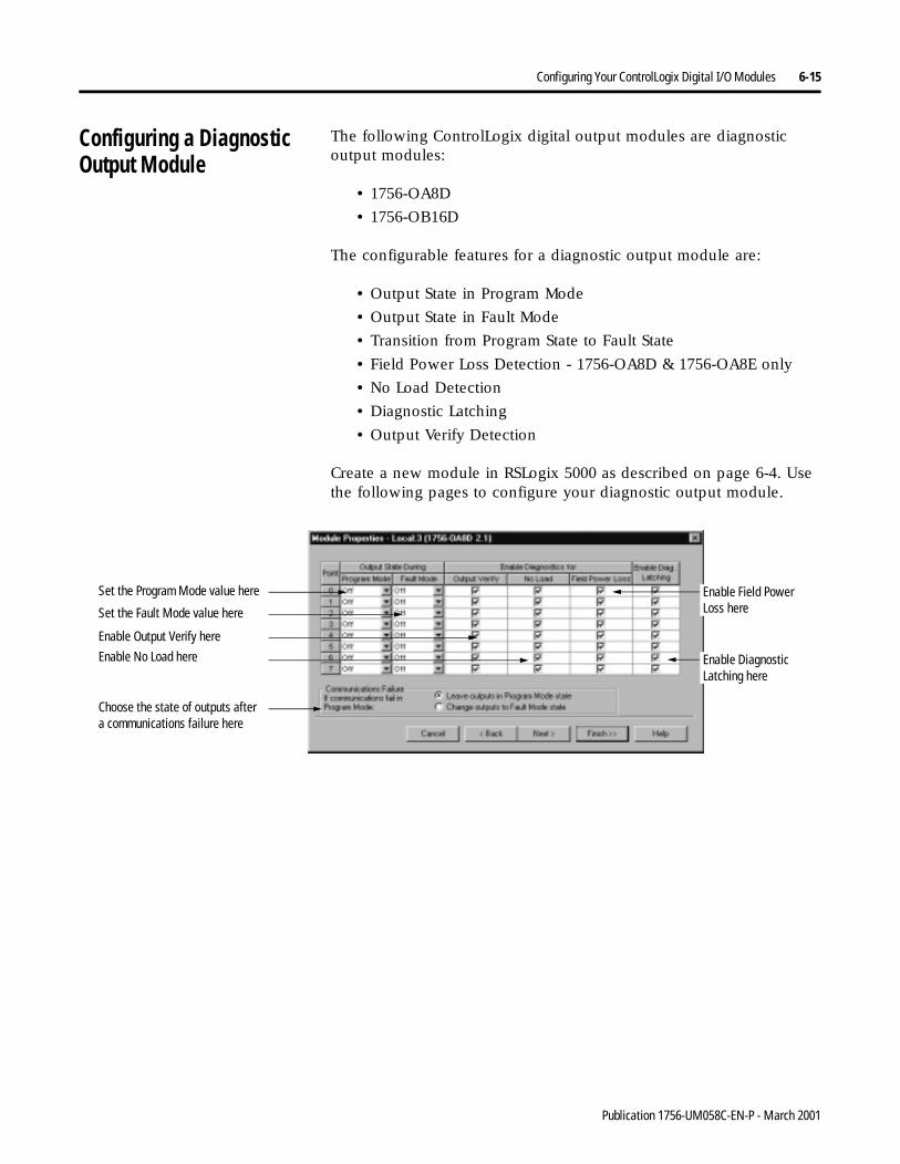
Configuring Your ControlLogix Digital I/O Modules 6-15
Configuring a DiagnosticOutput Module
The following ControlLogix digital output modules are diagnostic output modules:
• 1756-OA8D
• 1756-OB16D
The configurable features for a diagnostic output module are:
• Output State in Program Mode
• Output State in Fault Mode
• Transition from Program State to Fault State
• Field Power Loss Detection - 1756-OA8D & 1756-OA8E only
• No Load Detection
• Diagnostic Latching
• Output Verify Detection
Create a new module in RSLogix 5000 as described on page 6-4. Use the following pages to configure your diagnostic output module.
Set the Program Mode value here
Set the Fault Mode value here
Enable No Load here
Choose the state of outputs after a communications failure here
Enable Diagnostic Latching here
Enable Field Power Loss here
Enable Output Verify here
Publication 1756-UM058C-EN-P - March 2001
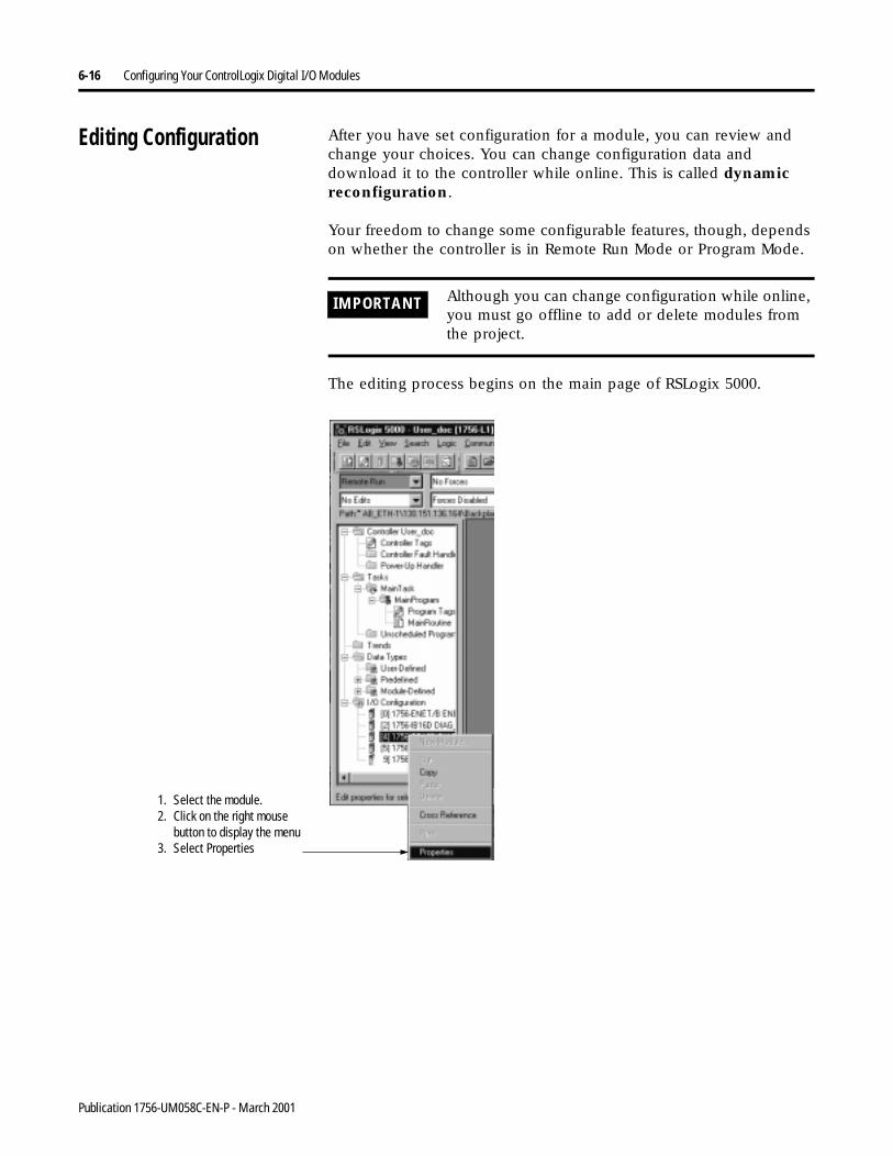
6-16 Configuring Your ControlLogix Digital I/O Modules
Editing Configuration After you have set configuration for a module, you can review and change your choices. You can change configuration data and download it to the controller while online. This is called dynamic reconfiguration.
Your freedom to change some configurable features, though, depends on whether the controller is in Remote Run Mode or Program Mode.
The editing process begins on the main page of RSLogix 5000.
IMPORTANT Although you can change configuration while online, you must go offline to add or delete modules from the project.
1. Select the module.2. Click on the right mouse
button to display the menu3. Select Properties
Publication 1756-UM058C-EN-P - March 2001
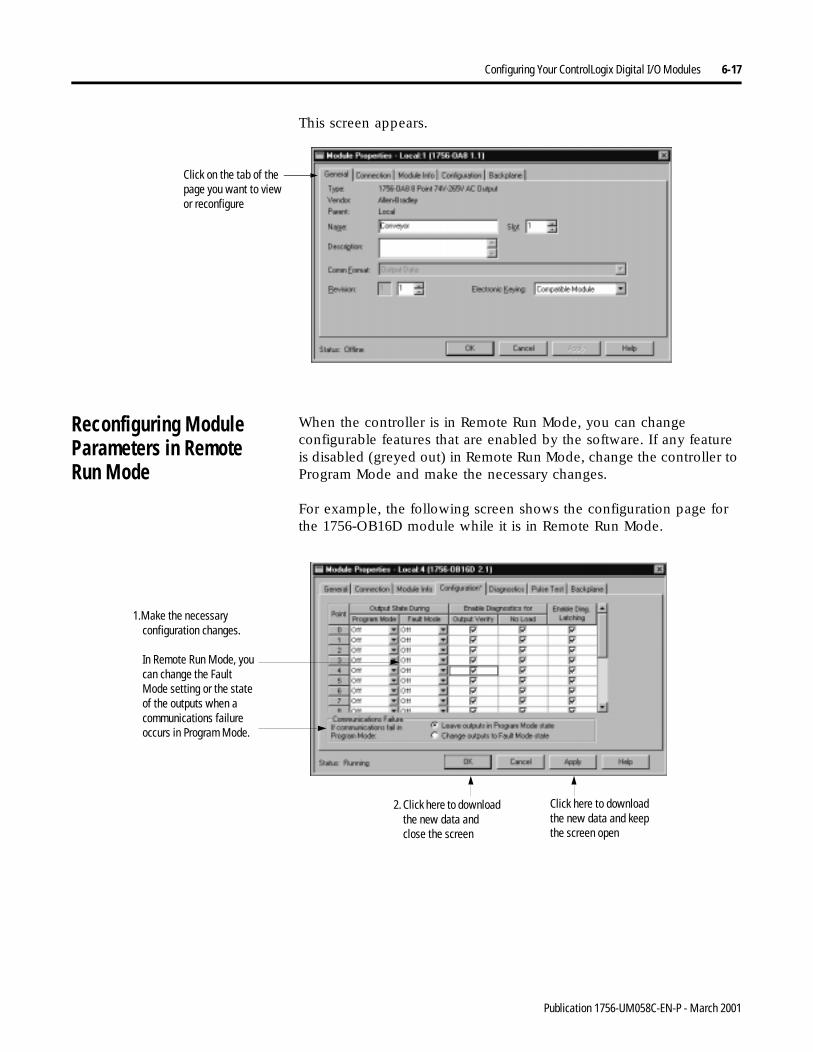
Configuring Your ControlLogix Digital I/O Modules 6-17
This screen appears.
Reconfiguring Module Parameters in RemoteRun Mode
When the controller is in Remote Run Mode, you can change configurable features that are enabled by the software. If any feature is disabled (greyed out) in Remote Run Mode, change the controller to Program Mode and make the necessary changes.
For example, the following screen shows the configuration page for the 1756-OB16D module while it is in Remote Run Mode.
Click on the tab of the page you want to view or reconfigure
1.Make the necessary configuration changes.
In Remote Run Mode, you can change the Fault Mode setting or the state of the outputs when a communications failure occurs in Program Mode.
2. Click here to download the new data and close the screen
Click here to download the new data and keep the screen open
Publication 1756-UM058C-EN-P - March 2001
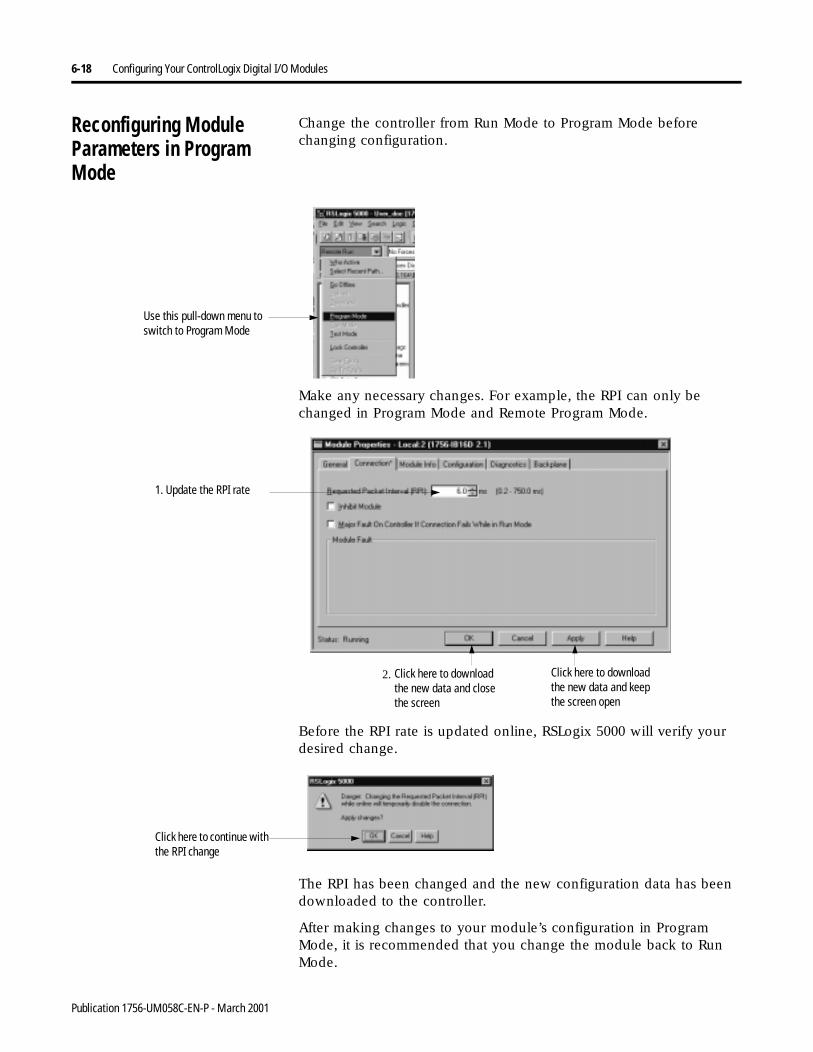
6-18 Configuring Your ControlLogix Digital I/O Modules
Reconfiguring Module Parameters in Program Mode
Change the controller from Run Mode to Program Mode before changing configuration.
Make any necessary changes. For example, the RPI can only be changed in Program Mode and Remote Program Mode.
Before the RPI rate is updated online, RSLogix 5000 will verify your desired change.
The RPI has been changed and the new configuration data has been downloaded to the controller.
After making changes to your module’s configuration in Program Mode, it is recommended that you change the module back to Run Mode.
Use this pull-down menu to switch to Program Mode
1. Update the RPI rate
Click here to download the new data and close the screen
2. Click here to download the new data and keep the screen open
Click here to continue with the RPI change
Publication 1756-UM058C-EN-P - March 2001
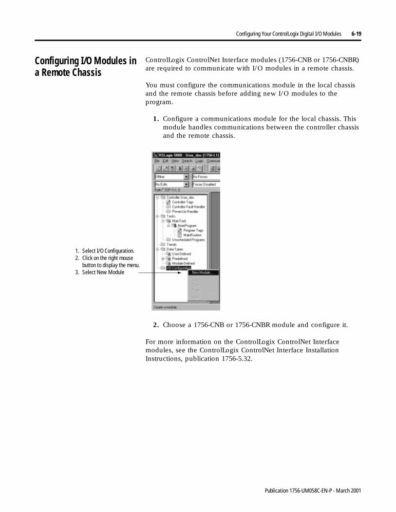
Configuring Your ControlLogix Digital I/O Modules 6-19
Configuring I/O Modules in a Remote Chassis
ControlLogix ControlNet Interface modules (1756-CNB or 1756-CNBR) are required to communicate with I/O modules in a remote chassis.
You must configure the communications module in the local chassis and the remote chassis before adding new I/O modules to the program.
1. Configure a communications module for the local chassis. This module handles communications between the controller chassis and the remote chassis.
2. Choose a 1756-CNB or 1756-CNBR module and configure it.
For more information on the ControlLogix ControlNet Interface modules, see the ControlLogix ControlNet Interface Installation Instructions, publication 1756-5.32.
1. Select I/O Configuration.2. Click on the right mouse
button to display the menu.3. Select New Module
Publication 1756-UM058C-EN-P - March 2001
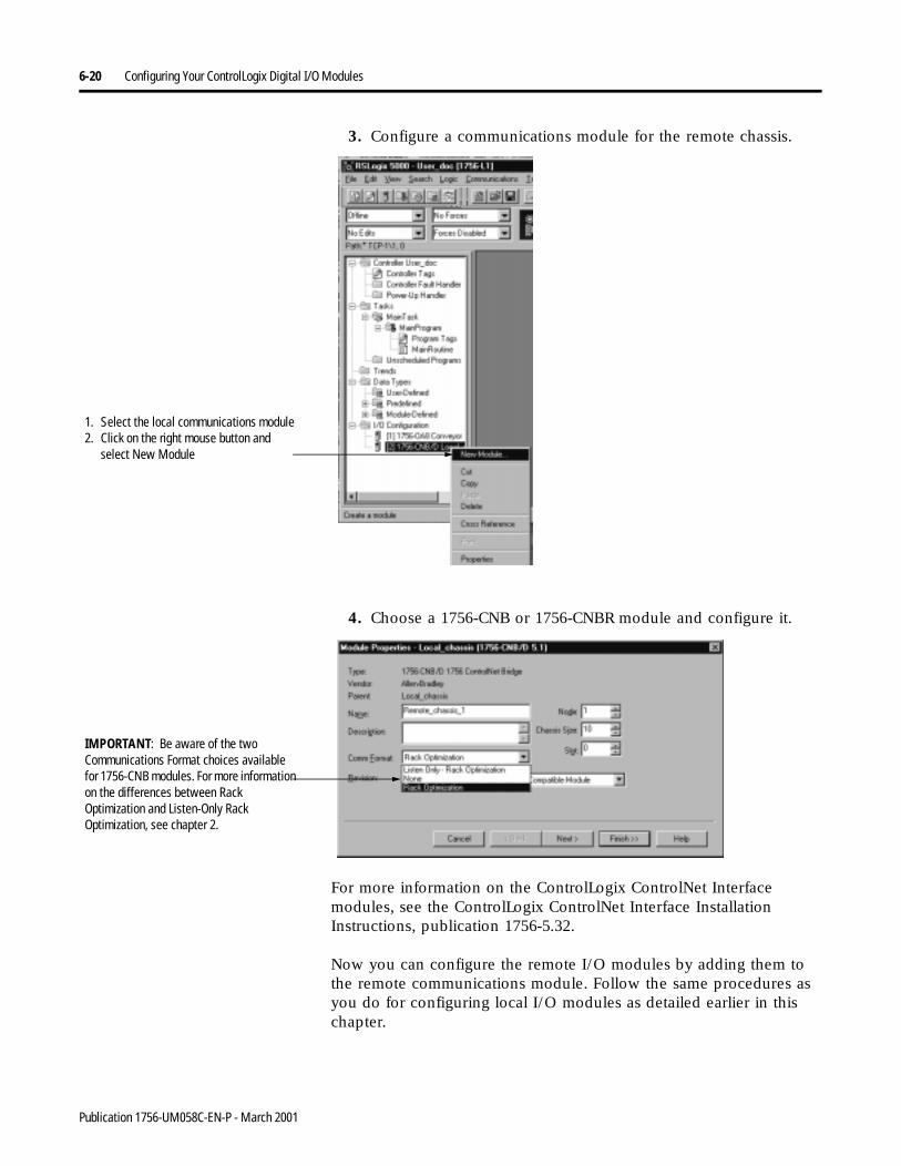
6-20 Configuring Your ControlLogix Digital I/O Modules
3. Configure a communications module for the remote chassis.
4. Choose a 1756-CNB or 1756-CNBR module and configure it.
For more information on the ControlLogix ControlNet Interface modules, see the ControlLogix ControlNet Interface Installation Instructions, publication 1756-5.32.
Now you can configure the remote I/O modules by adding them to the remote communications module. Follow the same procedures as you do for configuring local I/O modules as detailed earlier in this chapter.
1. Select the local communications module2. Click on the right mouse button and
select New Module
IMPORTANT: Be aware of the two Communications Format choices available for 1756-CNB modules. For more information on the differences between Rack Optimization and Listen-Only Rack Optimization, see chapter 2.
Publication 1756-UM058C-EN-P - March 2001
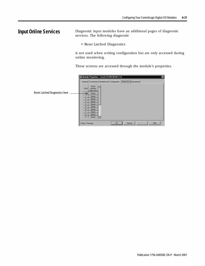
Configuring Your ControlLogix Digital I/O Modules 6-21
Input Online Services Diagnostic input modules have an additional pages of diagnostic services. The following diagnostic
• Reset Latched Diagnostics
is not used when writing configuration but are only accessed during online monitoring.
These screens are accessed through the module’s properties.
Reset Latched Diagnostics here
Publication 1756-UM058C-EN-P - March 2001
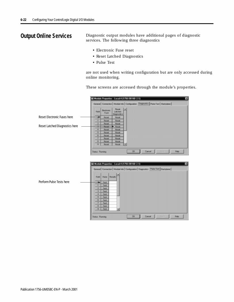
6-22 Configuring Your ControlLogix Digital I/O Modules
Output Online Services Diagnostic output modules have additional pages of diagnostic services. The following three diagnostics
• Electronic Fuse reset
• Reset Latched Diagnostics
• Pulse Test
are not used when writing configuration but are only accessed during online monitoring.
These screens are accessed through the module’s properties.
Reset Electronic Fuses here
Reset Latched Diagnostics here
Perform Pulse Tests here
Publication 1756-UM058C-EN-P - March 2001
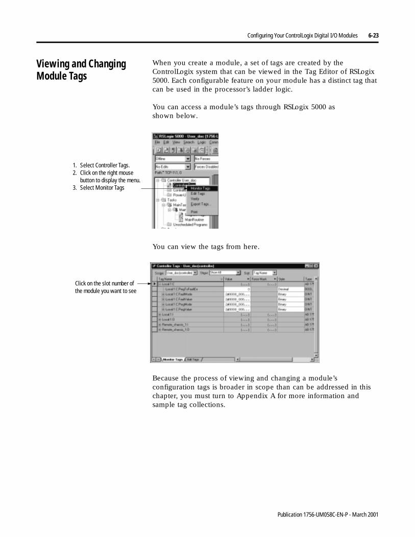
Configuring Your ControlLogix Digital I/O Modules 6-23
Viewing and ChangingModule Tags
When you create a module, a set of tags are created by the ControlLogix system that can be viewed in the Tag Editor of RSLogix 5000. Each configurable feature on your module has a distinct tag that can be used in the processor’s ladder logic.
You can access a module’s tags through RSLogix 5000 asshown below.
You can view the tags from here.
Because the process of viewing and changing a module’s configuration tags is broader in scope than can be addressed in this chapter, you must turn to Appendix A for more information and sample tag collections.
1. Select Controller Tags.2. Click on the right mouse
button to display the menu.3. Select Monitor Tags
Click on the slot number of the module you want to see
Publication 1756-UM058C-EN-P - March 2001
6-24 Configuring Your ControlLogix Digital I/O Modules
Chapter Summary andWhat’s Next
In this chapter you learned about:
• configuring ControlLogix digital I/O modules
• configuration tags
• editing module configuration
Move on to Chapter 7, Module-Specific Information.
Publication 1756-UM058C-EN-P - March 2001
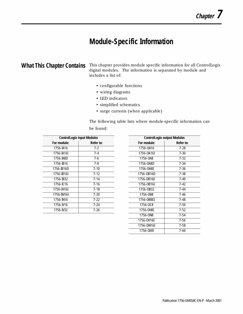
Chapter 7
Module-Specific Information
What This Chapter Contains This chapter provides module specific information for all ControlLogix digital modules. The information is separated by module and includes a list of:
• configurable functions
• wiring diagrams
• LED indicators
• simplified schematics
• surge currents (when applicable)
The following table lists where module-specific information can
be found: ControlLogix input Modules ControlLogix output Modules
For module: Refer to: For module: Refer to:1756-IA16 7-2 1756-OA16 7-28
1756-IA16I 7-4 1756-OA16I 7-30
1756-IA8D 7-6 1756-OA8 7-32
1756-IB16 7-8 1756-OA8D 7-34
1756-IB16D 7-10 1756-OA8E 7-36
1756-IB16I 7-12 1756-OB16D 7-38
1756-IB32 7-14 1756-OB16E 7-40
1756-IC16 7-16 1756-OB16I 7-42
1756-IH16I 7-18 1756-OB32 7-44
1756-IM16I 7-20 1756-OB8 7-46
1756-IN16 7-22 1756-OB8EI 7-48
1756-IV16 7-24 1756-OC8 7-50
1756-IV32 7-26 1756-OH8I 7-52
1756-ON8 7-54
1756-OV16E 7-56
1756-OW16I 7-58
1756-OX8I 7-60
1 Publication 1756-UM058C-EN-P - March 2001
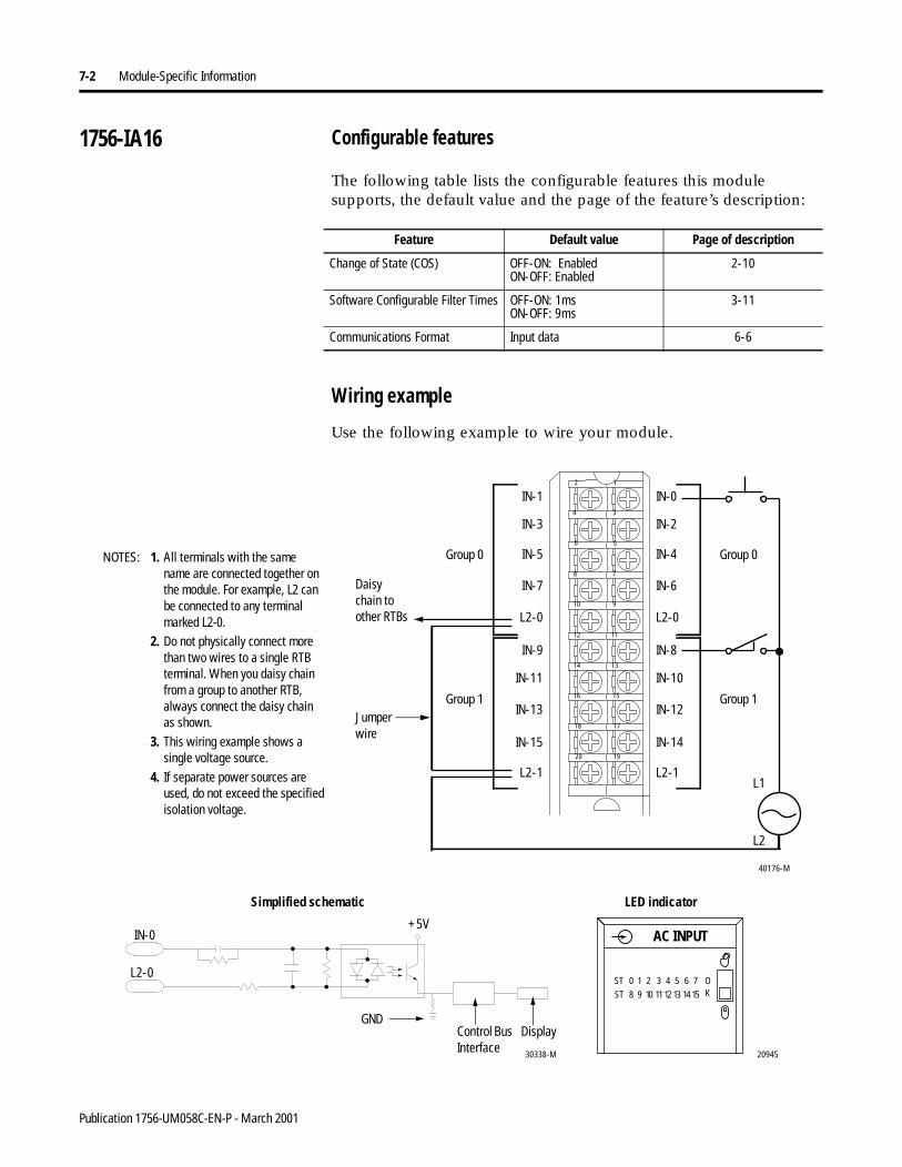
7-2 Module-Specific Information
1756-IA16 Configurable features
The following table lists the configurable features this module supports, the default value and the page of the feature’s description:
Wiring example
Use the following example to wire your module.
Feature Default value Page of description
Change of State (COS) OFF-ON: EnabledON-OFF: Enabled
2-10
Software Configurable Filter Times OFF-ON: 1msON-OFF: 9ms
3-11
Communications Format Input data 6-6
NOTES:
IN-9
IN-11
IN-13
IN-15
L2-1
IN-1
IN-3
IN-5
IN-7
L2-0
IN-8
IN-10
IN-12
IN-14
L2-1
IN-0
IN-2
IN-4
IN-6
L2-0
12
34
56
78
910
1112
1314
1516
1718
1920
L2
L1
Group 0
Group 1
40176-M
Daisy chain to other RTBs
Group 0
Group 1
20945
ST 0 1 2 3 4 5 6 7
ST 8 9 10 1112 13 14 15
OK
AC INPUT+5V
Control Bus Interface
IN-0
L2-0
30338-M
GNDDisplay
Simplified schematic LED indicator
Jumper wire
1. All terminals with the samename are connected together on the module. For example, L2 canbe connected to any terminal marked L2-0.
2. Do not physically connect more than two wires to a single RTB terminal. When you daisy chain from a group to another RTB, always connect the daisy chainas shown.
3. This wiring example shows a single voltage source.
4. If separate power sources areused, do not exceed the specified isolation voltage.
Publication 1756-UM058C-EN-P - March 2001
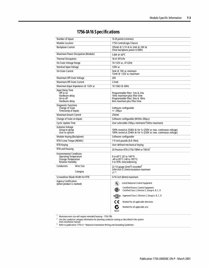
Module-Specific Information 7-3
1756-IA16 Specifications Number of Inputs 16 (8 points/common)
Module Location 1756 ControlLogix Chassis
Backplane Current 105mA @ 5.1V dc & 2mA @ 24V dc(Total backplane power 0.58W)
Maximum Power Dissipation (Module) 5.8W @ 60oC
Thermal Dissipation 18.41 BTU/hr
On-State Voltage Range 74-132V ac, 47-63Hz
Nominal Input Voltage 120V ac
On-State Current 5mA @ 74V ac minimum13mA @ 132V ac maximum
Maximum Off-State Voltage 20V
Maximum Off-State Current 2.5mA
Maximum Input Impedance @ 132V ac 10.15kΩ @ 60Hz
Input Delay TimeOff to onHardware delayOn to offHardware delay
Programmable filter: 1ms & 2ms10ms maximum plus filter timeProgrammable filter: 9ms & 18ms8ms maximum plus filter time
Diagnostic FunctionsChange of StateTimestamp of Inputs
Software configurable+/- 200µs
Maximum Inrush Current 250mA
Change of State on Inputs Software configurable (Within 200µs)
Cyclic Update Time User selectable (100µs minimum/750ms maximum)
Isolation VoltageGroup to groupUser to system
100% tested at 2546V dc for 1s (250V ac max. continuous voltage)100% tested at 2546V dc for 1s (250V ac max. continuous voltage)
Module Keying (Backplane) Software configurable
RTB Screw Torque (NEMA) 7-9 inch-pounds (0.8-1Nm)
RTB Keying User defined mechanical keying
RTB and Housing 20 Position RTB (1756-TBNH or TBSH)1
Environmental ConditionsOperating TemperatureStorage TemperatureRelative Humidity
0 to 60°C (32 to 140°F)-40 to 85°C (-40 to 185°F)5 to 95% noncondensing
Conductors Wire Size
Category
22-14 gauge (2mm2) stranded1
3/64 inch (1.2mm) insulation maximum12, 3
Screwdriver Blade Width for RTB 5/16 inch (8mm) maximum
Agency Certification(when product is marked)
1 Maximum wire size will require extended housing - 1756-TBE.2 Use this conductor category information for planning conductor routing as described in the system
level installation manual.3 Refer to publication 1770-4.1 “Industrial Automation Wiring and Grounding Guidelines’.
Marked for all applicable directives
Approved Class I, Division 2, Group A, B, C, D
Certified Process Control EquipmentCertified Class I, Division 2, Group A, B, C, D
Marked for all applicable acts
N223
Listed Industrial Control Equipment
Publication 1756-UM058C-EN-P - March 2001
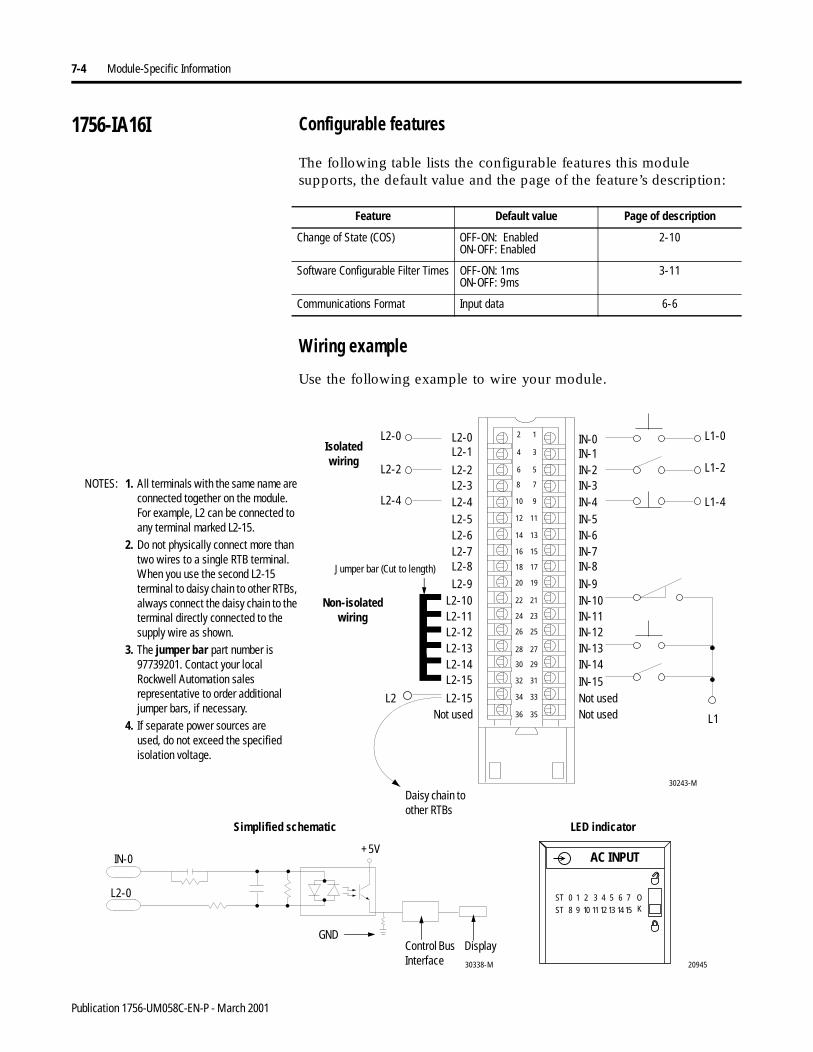
7-4 Module-Specific Information
1756-IA16I Configurable features
The following table lists the configurable features this module supports, the default value and the page of the feature’s description:
Wiring example
Use the following example to wire your module.
Feature Default value Page of description
Change of State (COS) OFF-ON: EnabledON-OFF: Enabled
2-10
Software Configurable Filter Times OFF-ON: 1msON-OFF: 9ms
3-11
Communications Format Input data 6-6
Non-isolated wiring
Isolatedwiring
1. All terminals with the same name are connected together on the module. For example, L2 can be connected to any terminal marked L2-15.
2. Do not physically connect more than two wires to a single RTB terminal. When you use the second L2-15 terminal to daisy chain to other RTBs, always connect the daisy chain to the terminal directly connected to the supply wire as shown.
3. The jumper bar part number is 97739201. Contact your local Rockwell Automation sales representative to order additional jumper bars, if necessary.
4. If separate power sources areused, do not exceed the specified isolation voltage.
30243-M
L2-0
L2-11
L2-1
L2-10
L2-2
L2-9
L2-6
L2-3
L2-7
L2-4
L2-8
L2-5
L2-15L2-14
L2-15
L2-12L2-13
IN-0
IN-8
IN-5
IN-7
IN-9IN-10IN-11IN-12IN-13IN-14
IN-15
IN-4
IN-6
IN-1IN-2IN-3
12
34
56
78
910
1112
1314
1516
1718
1920
2122
2324
2526
2728
2930
3132
3334
3536Not usedNot usedNot used
L1-0
L2-2
L1-4
L2-0
L1-2
L2-4
L2
Daisy chain to other RTBs
Jumper bar (Cut to length)
L1
20945
ST 0 1 2 3 4 5 6 7
ST 8 9 10 11 12 13 1415
OK
AC INPUT+5V
Control Bus Interface
IN-0
L2-0
30338-M
GNDDisplay
Simplified schematic LED indicator
NOTES:
Publication 1756-UM058C-EN-P - March 2001
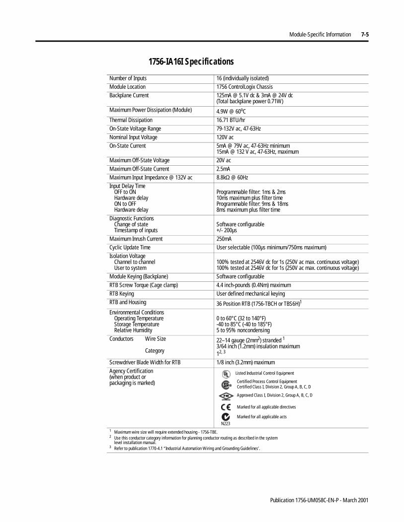
Module-Specific Information 7-5
1756-IA16I Specifications
Number of Inputs 16 (individually isolated)Module Location 1756 ControlLogix ChassisBackplane Current 125mA @ 5.1V dc & 3mA @ 24V dc
(Total backplane power 0.71W)Maximum Power Dissipation (Module) 4.9W @ 60oCThermal Dissipation 16.71 BTU/hrOn-State Voltage Range 79-132V ac, 47-63HzNominal Input Voltage 120V acOn-State Current 5mA @ 79V ac, 47-63Hz minimum
15mA @ 132 V ac, 47-63Hz, maximumMaximum Off-State Voltage 20V acMaximum Off-State Current 2.5mAMaximum Input Impedance @ 132V ac 8.8kΩ @ 60HzInput Delay Time
OFF to ONHardware delayON to OFFHardware delay
Programmable filter: 1ms & 2ms10ms maximum plus filter timeProgrammable filter: 9ms & 18ms8ms maximum plus filter time
Diagnostic FunctionsChange of stateTimestamp of inputs
Software configurable+/- 200µs
Maximum Inrush Current 250mACyclic Update Time User selectable (100µs minimum/750ms maximum)Isolation Voltage
Channel to channelUser to system
100% tested at 2546V dc for 1s (250V ac max. continuous voltage)100% tested at 2546V dc for 1s (250V ac max. continuous voltage)
Module Keying (Backplane) Software configurableRTB Screw Torque (Cage clamp) 4.4 inch-pounds (0.4Nm) maximumRTB Keying User defined mechanical keyingRTB and Housing 36 Position RTB (1756-TBCH or TBS6H)1
Environmental ConditionsOperating TemperatureStorage TemperatureRelative Humidity
0 to 60°C (32 to 140°F)-40 to 85°C (-40 to 185°F)5 to 95% noncondensing
Conductors Wire Size
Category
22–14 gauge (2mm2) stranded 13/64 inch (1.2mm) insulation maximum12, 3
Screwdriver Blade Width for RTB 1/8 inch (3.2mm) maximumAgency Certification(when product orpackaging is marked)
1 Maximum wire size will require extended housing - 1756-TBE.2 Use this conductor category information for planning conductor routing as described in the system
level installation manual.3 Refer to publication 1770-4.1 “Industrial Automation Wiring and Grounding Guidelines’.
Marked for all applicable directives
Approved Class I, Division 2, Group A, B, C, D
Certified Process Control EquipmentCertified Class I, Division 2, Group A, B, C, D
Marked for all applicable actsN223
Listed Industrial Control Equipment
Publication 1756-UM058C-EN-P - March 2001
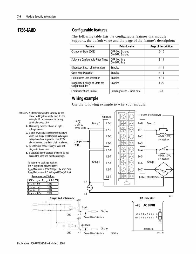
7-6 Module-Specific Information
1756-IA8D Configurable featuresThe following table lists the configurable features this module supports, the default value and the page of the feature’s description:
Wiring exampleUse the following example to wire your module.
Feature Default value Page of description
Change of State (COS) OFF-ON: EnabledON-OFF: Enabled
2-10
Software Configurable Filter Times OFF-ON: 1msON-OFF: 9ms
3-11
Diagnostic Latch of Information Enabled 4-11
Open Wire Detection Enabled 4-15
Field Power Loss Detection Enabled 4-16
Diagnostic Change of State for Output Modules
Enabled 4-25
Communications Format Full diagnostics - input data 6-6
Not used
L2-0
L2-0
L2-0
L2-0
L2-1
L2-1
L2-1
L2-1
L2-1
IN-4
IN-5
IN-6
IN-7
IN-0
IN-1
IN-2
IN-3
12
34
56
78
910
1112
1314
1516
1718
1920
62kΩ, 1/2W, 5% resistor
62kΩ, 1/2W, 5% resistor
L2
L140202
1. All terminals with the same name are connected together on the module. For example, L2 can be connected to anyterminal marked L2-0.
2. This wiring example shows a singlevoltage source.
3. Do not physically connect more than twowires to a single RTB terminal. When youdaisy chain from a group to other RTBs,always connect the daisy chain as shown.
4. Resistors are not necessary if Wire Off diagnostic is not used.
5. If separate power sources are used, do not exceed the specified isolation voltage.
To Determine Leakage Resistor(P/S = Field side power supply)RLEAKMaximum = (P/S Voltage-19V ac)/1.5mARLEAKMinimum = (P/S Voltage-20V ac)/2.5mA
Daisy chain to other RTBs
Recommended Values369ROWDJH 5/($.:
9DF 43kΩ9DF 47kΩ9DF 47kΩ9DF 51kΩ
Group 0 Group 0
Group 1 Group 1
L1-1 Loss of Field Power
L1-0 Loss of Field Power
20927-M
AC INPUT
ST
FLT
0 1 2 3 4 5 6 7
0 1 2 3 4 5 6 7
OK
DIAGNOSTIC
+5V
30340-MControl Bus Interface
Control Bus Interface
+5V
Display
Simplified schematic LED indicator
Input
DisplayOpen wire
GND
GND
NOTES:
Jumper wire
Publication 1756-UM058C-EN-P - March 2001
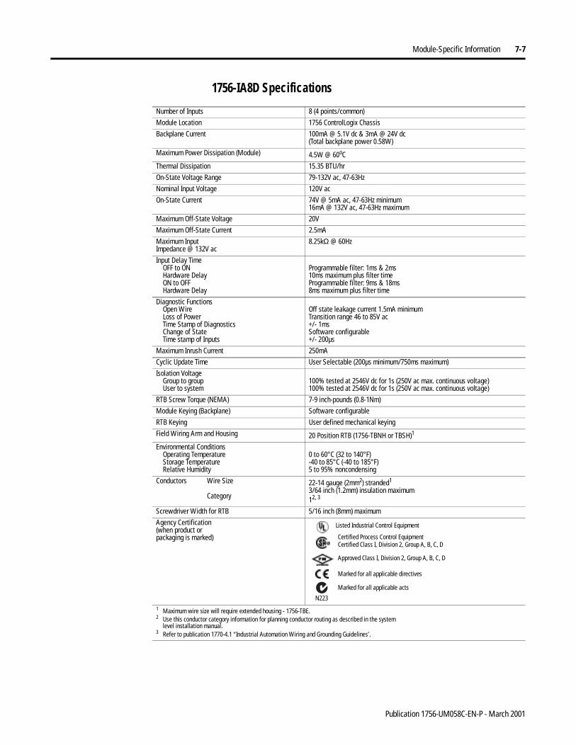
Module-Specific Information 7-7
1756-IA8D Specifications
Number of Inputs 8 (4 points/common)
Module Location 1756 ControlLogix Chassis
Backplane Current 100mA @ 5.1V dc & 3mA @ 24V dc(Total backplane power 0.58W)
Maximum Power Dissipation (Module) 4.5W @ 60oC
Thermal Dissipation 15.35 BTU/hr
On-State Voltage Range 79-132V ac, 47-63Hz
Nominal Input Voltage 120V ac
On-State Current 74V @ 5mA ac, 47-63Hz minimum16mA @ 132V ac, 47-63Hz maximum
Maximum Off-State Voltage 20V
Maximum Off-State Current 2.5mA
Maximum InputImpedance @ 132V ac
8.25kΩ @ 60Hz
Input Delay TimeOFF to ONHardware DelayON to OFFHardware Delay
Programmable filter: 1ms & 2ms10ms maximum plus filter timeProgrammable filter: 9ms & 18ms8ms maximum plus filter time
Diagnostic FunctionsOpen WireLoss of PowerTime Stamp of DiagnosticsChange of StateTime stamp of Inputs
Off state leakage current 1.5mA minimumTransition range 46 to 85V ac+/- 1msSoftware configurable+/- 200µs
Maximum Inrush Current 250mA
Cyclic Update Time User Selectable (200µs minimum/750ms maximum)
Isolation VoltageGroup to groupUser to system
100% tested at 2546V dc for 1s (250V ac max. continuous voltage)100% tested at 2546V dc for 1s (250V ac max. continuous voltage)
RTB Screw Torque (NEMA) 7-9 inch-pounds (0.8-1Nm)
Module Keying (Backplane) Software configurable
RTB Keying User defined mechanical keying
Field Wiring Arm and Housing 20 Position RTB (1756-TBNH or TBSH)1
Environmental ConditionsOperating TemperatureStorage TemperatureRelative Humidity
0 to 60°C (32 to 140°F)-40 to 85°C (-40 to 185°F)5 to 95% noncondensing
Conductors Wire Size
Category
22-14 gauge (2mm2) stranded1
3/64 inch (1.2mm) insulation maximum12, 3
Screwdriver Width for RTB 5/16 inch (8mm) maximum
Agency Certification(when product orpackaging is marked)
1 Maximum wire size will require extended housing - 1756-TBE.2 Use this conductor category information for planning conductor routing as described in the system
level installation manual.3 Refer to publication 1770-4.1 “Industrial Automation Wiring and Grounding Guidelines’.
Marked for all applicable directives
Approved Class I, Division 2, Group A, B, C, D
Certified Process Control EquipmentCertified Class I, Division 2, Group A, B, C, D
Marked for all applicable acts
N223
Listed Industrial Control Equipment
Publication 1756-UM058C-EN-P - March 2001
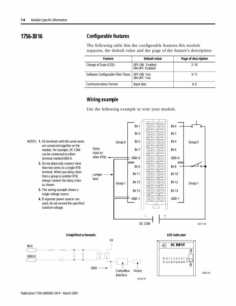
7-8 Module-Specific Information
1756-IB16 Configurable features
The following table lists the configurable features this module supports, the default value and the page of the feature’s description:
Wiring example
Use the following example to wire your module.
Feature Default value Page of description
Change of State (COS) OFF-ON: EnabledON-OFF: Enabled
2-10
Software Configurable Filter Times OFF-ON: 1msON-OFF: 1ms
3-11
Communications Format Input data 6-6
IN-9
IN-11
IN-13
IN-15
GND-1
IN-1
IN-3
IN-5
IN-7
GND-0
IN-8
IN-10
IN-12
IN-14
GND-1
IN-0
IN-2
IN-4
IN-6
GND-0
12
34
56
78
910
1112
1314
1516
1718
1920
1. All terminals with the same name are connected together on the module. For example, DC COM can be connected to either terminal marked GND-0.
2. Do not physically connect more than two wires to a single RTB terminal. When you daisy chain from a group to another RTB, always connect the daisy chainas shown.
3. This wiring example shows a single voltage source.
4. If separate power sources areused, do not exceed the specified isolation voltage.
40177-M
– +
DC COM
Group 0
Group 1
NOTES: Group 0
Group 1
Daisy chain to other RTBs
ControlBusInterface
5V
30183-M
20945-M
DC INPUT
ST 0 1 2 3 4 5 6 7
ST 8 9 10 11 12 13 14 15
OK
Simplified schematic LED indicator
DisplayGND
GND-0
IN-0
Jumper wire
Publication 1756-UM058C-EN-P - March 2001
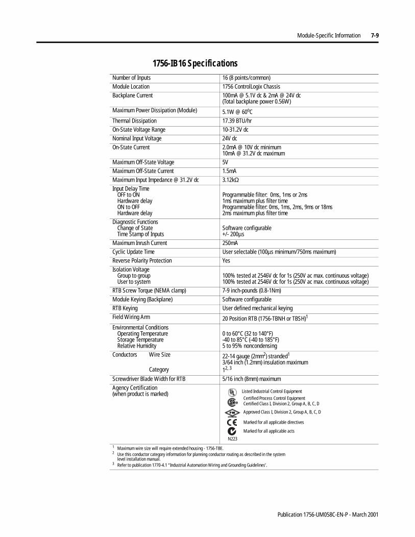
Module-Specific Information 7-9
1756-IB16 Specifications Number of Inputs 16 (8 points/common)Module Location 1756 ControlLogix ChassisBackplane Current 100mA @ 5.1V dc & 2mA @ 24V dc
(Total backplane power 0.56W)Maximum Power Dissipation (Module) 5.1W @ 60oCThermal Dissipation 17.39 BTU/hrOn-State Voltage Range 10-31.2V dcNominal Input Voltage 24V dcOn-State Current 2.0mA @ 10V dc minimum
10mA @ 31.2V dc maximumMaximum Off-State Voltage 5VMaximum Off-State Current 1.5mA Maximum Input Impedance @ 31.2V dc 3.12kΩInput Delay Time
OFF to ONHardware delayON to OFFHardware delay
Programmable filter: 0ms, 1ms or 2ms1ms maximum plus filter timeProgrammable filter: 0ms, 1ms, 2ms, 9ms or 18ms2ms maximum plus filter time
Diagnostic FunctionsChange of StateTime Stamp of Inputs
Software configurable+/- 200µs
Maximum Inrush Current 250mACyclic Update Time User selectable (100µs minimum/750ms maximum)Reverse Polarity Protection YesIsolation Voltage
Group to groupUser to system
100% tested at 2546V dc for 1s (250V ac max. continuous voltage)100% tested at 2546V dc for 1s (250V ac max. continuous voltage)
RTB Screw Torque (NEMA clamp) 7-9 inch-pounds (0.8-1Nm)Module Keying (Backplane) Software configurableRTB Keying User defined mechanical keyingField Wiring Arm 20 Position RTB (1756-TBNH or TBSH)1
Environmental ConditionsOperating TemperatureStorage TemperatureRelative Humidity
0 to 60°C (32 to 140°F)-40 to 85°C (-40 to 185°F)5 to 95% noncondensing
Conductors Wire Size
Category
22-14 gauge (2mm2) stranded1
3/64 inch (1.2mm) insulation maximum12, 3
Screwdriver Blade Width for RTB 5/16 inch (8mm) maximumAgency Certification(when product is marked)
1 Maximum wire size will require extended housing - 1756-TBE.2 Use this conductor category information for planning conductor routing as described in the system
level installation manual.3 Refer to publication 1770-4.1 “Industrial Automation Wiring and Grounding Guidelines’.
Marked for all applicable directives
Approved Class I, Division 2, Group A, B, C, D
Certified Process Control EquipmentCertified Class I, Division 2, Group A, B, C, D
Marked for all applicable acts
N223
Listed Industrial Control Equipment
Publication 1756-UM058C-EN-P - March 2001
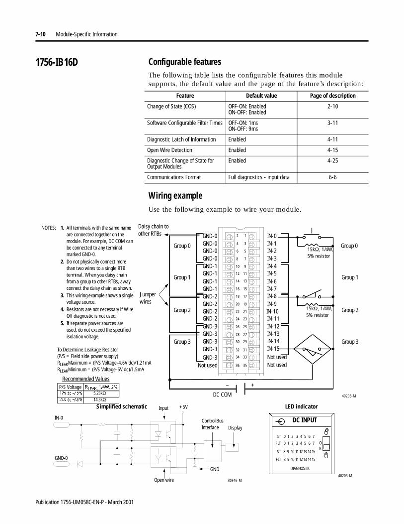
7-10 Module-Specific Information
1756-IB16D Configurable featuresThe following table lists the configurable features this module supports, the default value and the page of the feature’s description:
Wiring exampleUse the following example to wire your module.
Feature Default value Page of description
Change of State (COS) OFF-ON: EnabledON-OFF: Enabled
2-10
Software Configurable Filter Times OFF-ON: 1msON-OFF: 9ms
3-11
Diagnostic Latch of Information Enabled 4-11
Open Wire Detection Enabled 4-15
Diagnostic Change of State for Output Modules
Enabled 4-25
Communications Format Full diagnostics - input data 6-6
40203-M
1. All terminals with the same name are connected together on the module. For example, DC COM can be connected to any terminal marked GND-0.
2. Do not physically connect more than two wires to a single RTB terminal. When you daisy chain from a group to other RTBs, away connect the daisy chain as shown.
3. This wiring example shows a single voltage source.
4. Resistors are not necessary if Wire Off diagnostic is not used.
5. If separate power sources areused, do not exceed the specified isolation voltage.
12
34
56
78
910
1112
1314
1516
1718
1920
2122
2324
2526
2728
2930
3132
3334
3536
GND-0
GND-2
GND-0
GND-2
GND-0
GND-2
GND-1
GND-0
GND-1
GND-1
GND-2
GND-1
GND-3GND-3
GND-3
GND-3GND-3
IN-0
IN-8
IN-5
IN-7
IN-9IN-10IN-11IN-12IN-13IN-14IN-15
IN-4
IN-6
IN-1IN-2IN-3
Not usedNot usedNot used
DC COM
+–
15kΩ, 1/4W, 5% resistor
15kΩ, 1/4W, 5% resistor
To Determine Leakage Resistor(P/S = Field side power supply)RLEAKMaximum = (P/S Voltage-4.6V dc)/1.21mARLEAKMinimum = (P/S Voltage-5V dc)/1.5mA
NOTES: Daisy chain to other RTBs
Recommended Values
Group 0 Group 0
Group 1 Group 1
Group 2
Group 3
Group 2
Group 3
P/S Voltage 5/($.:9GF 5.23kΩ9GF 14.3kΩ
40203-M
FLT 8 9 10 11 12 13 14 15
ST 0 1 2 3 4 5 6 7
ST 8 9 10 11 12 13 14 15
OK
FLT 0 1 2 3 4 5 6 7
DC INPUT
DIAGNOSTIC
30346-M
Control Bus Interface
+5VSimplified schematic LED indicator
Display
GND
Open wire
GND-0
IN-0
Input
Jumper wires
Publication 1756-UM058C-EN-P - March 2001
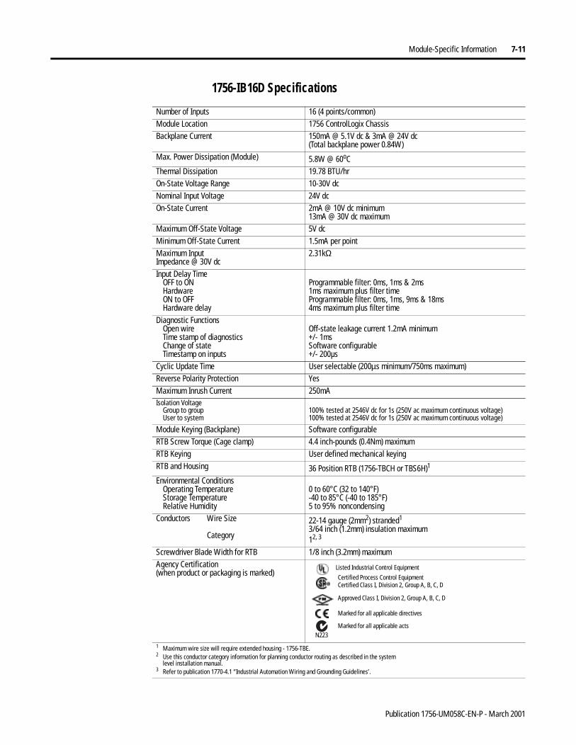
Module-Specific Information 7-11
1756-IB16D Specifications
Number of Inputs 16 (4 points/common)Module Location 1756 ControlLogix ChassisBackplane Current 150mA @ 5.1V dc & 3mA @ 24V dc
(Total backplane power 0.84W)Max. Power Dissipation (Module) 5.8W @ 60oCThermal Dissipation 19.78 BTU/hrOn-State Voltage Range 10-30V dcNominal Input Voltage 24V dcOn-State Current 2mA @ 10V dc minimum
13mA @ 30V dc maximumMaximum Off-State Voltage 5V dcMinimum Off-State Current 1.5mA per pointMaximum InputImpedance @ 30V dc
2.31kΩ
Input Delay TimeOFF to ONHardwareON to OFFHardware delay
Programmable filter: 0ms, 1ms & 2ms1ms maximum plus filter timeProgrammable filter: 0ms, 1ms, 9ms & 18ms4ms maximum plus filter time
Diagnostic FunctionsOpen wireTime stamp of diagnosticsChange of stateTimestamp on inputs
Off-state leakage current 1.2mA minimum+/- 1msSoftware configurable+/- 200µs
Cyclic Update Time User selectable (200µs minimum/750ms maximum)Reverse Polarity Protection YesMaximum Inrush Current 250mAIsolation Voltage
Group to groupUser to system
100% tested at 2546V dc for 1s (250V ac maximum continuous voltage)100% tested at 2546V dc for 1s (250V ac maximum continuous voltage)
Module Keying (Backplane) Software configurableRTB Screw Torque (Cage clamp) 4.4 inch-pounds (0.4Nm) maximumRTB Keying User defined mechanical keyingRTB and Housing 36 Position RTB (1756-TBCH or TBS6H)1
Environmental ConditionsOperating TemperatureStorage TemperatureRelative Humidity
0 to 60°C (32 to 140°F)-40 to 85°C (-40 to 185°F)5 to 95% noncondensing
Conductors Wire Size
Category
22-14 gauge (2mm2) stranded1
3/64 inch (1.2mm) insulation maximum12, 3
Screwdriver Blade Width for RTB 1/8 inch (3.2mm) maximumAgency Certification(when product or packaging is marked)
1 Maximum wire size will require extended housing - 1756-TBE.2 Use this conductor category information for planning conductor routing as described in the system
level installation manual.3 Refer to publication 1770-4.1 “Industrial Automation Wiring and Grounding Guidelines’.
Marked for all applicable directives
Approved Class I, Division 2, Group A, B, C, D
Certified Process Control EquipmentCertified Class I, Division 2, Group A, B, C, D
Marked for all applicable actsN223
Listed Industrial Control Equipment
Publication 1756-UM058C-EN-P - March 2001
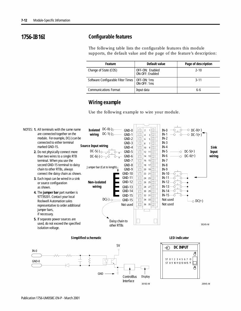
7-12 Module-Specific Information
1756-IB16I Configurable features
The following table lists the configurable features this module supports, the default value and the page of the feature’s description:
Wiring example
Use the following example to wire your module.
Feature Default value Page of description
Change of State (COS) OFF-ON: EnabledON-OFF: Enabled
2-10
Software Configurable Filter Times OFF-ON: 1msON-OFF: 1ms
3-11
Communications Format Input data 6-6
12
34
56
78
910
1112
1314
1516
1718
1920
2122
2324
2526
2728
2930
3132
3334
3536
GND-0
GND-11
GND-1
GND-10
GND-2
GND-9
GND-6
GND-3
GND-7
GND-4
GND-8
GND-5
GND-15GND-14
GND-15
GND-12
GND-13
IN-0
IN-8
IN-5
IN-7
IN-9IN-10IN-11IN-12IN-13IN-14IN-15
IN-4
IN-6
IN-1IN-2IN-3
Not usedNot usedNot used
Non-isolated wiring
Isolatedwiring
30245-M
DC(+)
DC-0(+)DC-1(-)DC-0(-)
DC-1(+)
DC-5(-)
DC(-)
DC-6(-)
1. All terminals with the same name are connected together on the module. For example, DC(-) can be connected to either terminal marked GND-15.
2. Do not physically connect more than two wires to a single RTB terminal. When you use the second GND-15 terminal to daisy chain to other RTBs, always connect the daisy chain as shown.
3. Each input can be wired in a sink or source configurationas shown.
4. The jumper bar part number is 97739201. Contact your local Rockwell Automation sales representative to order additional jumper bars,if necessary.
5. If separate power sources are used, do not exceed the specified isolation voltage.
DC-5(+)DC-6(+)
+–
+–
NOTES:
Daisy chain to other RTBs
Jumper bar (Cut to length)
Sink Input wiring
Source Input wiring
20945-M
ControlBusInterface
5V
30183-M
Simplified schematic LED indicator
Display
GND-0
GND
IN-0DC INPUT
ST 0 1 2 3 4 5 6 7
ST 8 9 10 1112 13 14 15
OK
Publication 1756-UM058C-EN-P - March 2001

Module-Specific Information 7-13
1756-IB16I Specifications
Number of Inputs 16 (individually isolated)Module Location 1756 ControlLogix ChassisBackplane Current 100mA @ 5.1V dc & 3mA @ 24V dc
(Total backplane power 0.58W)Maximum Power Dissipation (Module) 5W @ 60oCThermal Dissipation 17.05 BTU/hrOn-State Voltage Range 10-30V dcNominal Input Voltage 24V dcOn-State Current 2mA @ 10V dc minimum
10mA @ 30 V dc maximumMaximum Off-State Voltage 5V dcMaximum Off-State Current 1.5mAMax. Input Impedance @ 30V dc 3kΩ Input Delay Time
OFF to ONHardware delayON to OFFHardware delay
Programmable filter: 0ms, 1ms or 2ms1ms maximum plus filter timeProgrammable filter: 0ms, 1ms, 2ms, 9ms or 18ms4ms maximum plus filter time
Diagnostic FunctionsChange of stateTime stamp of inputs
Software configurable+/- 200µs
Maximum Inrush Current 250mACyclic Update Time User selectable (100µs minimum/750ms maximum)Reverse Polarity Protection YesIsolation Voltage
Channel to channelUser side to system side
100% tested at 2546V dc for 1 second (250V ac max. continuous voltage)100% tested at 2546V dc for 1 second (250V ac max. continuous voltage)
Module Keying (Backplane) Software configurableRTB Screw Torque (Cage clamp) 4.4 inch-pounds (0.4Nm) maximumRTB Keying User defined mechanical keyingRTB and Housing 36 Position RTB (1756-TBCH or TBS6H)1
Environmental ConditionsOperating TemperatureStorage TemperatureRelative Humidity
0 to 60°C (32 to 140°F)-40 to 85°C (-40 to 185°F)5 to 95% noncondensing
Conductors Wire Size
Category
22–14 gauge (2mm2) stranded1
3/64 inch (1.2mm) insulation maximum12, 3
Screwdriver Blade Width for RTB 1/8 inch (3.2mm) maximumAgency Certification(when product orpackaging is marked)
1 Maximum wire size will require extended housing - 1756-TBE.2 Use this conductor category information for planning conductor routing as described in the system
level installation manual.3 Refer to publication 1770-4.1 “Industrial Automation Wiring and Grounding Guidelines’.
Marked for all applicable directives
Approved Class I, Division 2, Group A, B, C, D
Certified Process Control EquipmentCertified Class I, Division 2, Group A, B, C, D
Marked for all applicable acts
N223
Listed Industrial Control Equipment
Publication 1756-UM058C-EN-P - March 2001
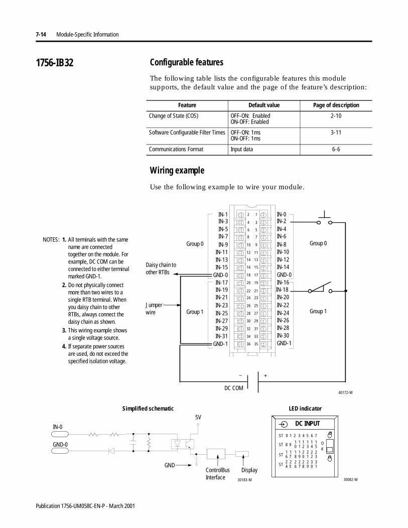
7-14 Module-Specific Information
1756-IB32 Configurable features
The following table lists the configurable features this module supports, the default value and the page of the feature’s description:
Wiring example
Use the following example to wire your module.
Feature Default value Page of description
Change of State (COS) OFF-ON: EnabledON-OFF: Enabled
2-10
Software Configurable Filter Times OFF-ON: 1msON-OFF: 1ms
3-11
Communications Format Input data 6-6
12
34
56
78
910
1112
1314
1516
1718
1920
2122
2324
2526
2728
2930
3132
3334
3536
IN-1
IN-21
IN-3
IN-19
IN-5
IN-17
IN-13
IN-7
IN-15
IN-9
GND-0
IN-11
IN-29IN-27
IN-31
IN-23IN-25
IN-0
GND-0
IN-10
IN-14
IN-16IN-18IN-20IN-22IN-24IN-26IN-28
IN-8
IN-12
IN-2IN-4IN-6
GND-1IN-30GND-1
40172-M
1. All terminals with the same name are connected together on the module. For example, DC COM can be connected to either terminal marked GND-1.
2. Do not physically connect more than two wires to a single RTB terminal. When you daisy chain to other RTBs, always connect the daisy chain as shown.
3. This wiring example shows a single voltage source.
4. If separate power sources are used, do not exceed the specified isolation voltage.
+–
DC COM
NOTES:
Daisy chain to other RTBs
Group 0
Group 1
Group 0
Group 1
30082-M
DC INPUT
OK
ST 0 1 2 3 4 5 6 7
ST 8 910 21 3 4 5
1 1 1 11
ST 6 718 09 1 2 3
1 2 2 221 1
ST 4 526 87 9 0 1
2 2 2 332 2
ControlBusInterface
5V
30183-M
Simplified schematic LED indicator
Display
GND-0
GND
IN-0
Jumper wire
Publication 1756-UM058C-EN-P - March 2001
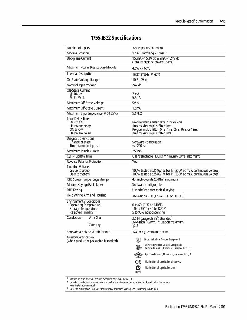
Module-Specific Information 7-15
1756-IB32 Specifications
Number of Inputs 32 (16 points/common)Module Location 1756 ControlLogix ChassisBackplane Current 150mA @ 5.1V dc & 2mA @ 24V dc
(Total backplane power 0.81W)Maximum Power Dissipation (Module) 4.5W @ 60oCThermal Dissipation 16.37 BTU/hr @ 60oCOn-State Voltage Range 10-31.2V dcNominal Input Voltage 24V dcON-State Current
@ 10V dc@ 31.2V dc
2.mA5.5mA
Maximum Off-State Voltage 5V dcMaximum Off-State Current 1.5mAMaximum Input Impedance @ 31.2V dc 5.67kΩInput Delay Time
OFF to ONHardware delayON to OFFHardware delay
Programmable filter: 0ms, 1ms or 2ms1ms maximum plus filter timeProgrammable filter: 0ms, 1ms, 2ms, 9ms or 18ms2ms maximum plus filter time
Diagnostic FunctionsChange of stateTime stamp on inputs
Software configurable+/- 200µs
Maximum Inrush Current 250mACyclic Update Time User selectable (100µs minimum/750ms maximum)Reverse Polarity Protection YesIsolation Voltage
Group to groupUser to system
100% tested at 2546V dc for 1s (250V ac max. continuous voltage)100% tested at 2546V dc for 1s (250V ac max. continuous voltage)
RTB Screw Torque (Cage clamp) 4.4 inch-pounds (0.4Nm) maximumModule Keying (Backplane) Software configurableRTB Keying User defined mechanical keyingField Wiring Arm and Housing 36 Position RTB (1756-TBCH or TBS6H)1
Environmental ConditionsOperating TemperatureStorage TemperatureRelative Humidity
0 to 60°C (32 to 140°F)-40 to 85°C (-40 to 185°F)5 to 95% noncondensing
Conductors Wire Size
Category
22-14 gauge (2mm2) stranded1
3/64 inch (1.2mm) insulation maximum12, 3
Screwdriver Blade Width for RTB 1/8 inch (3.2mm) maximumAgency Certification(when product or packaging is marked)
1 Maximum wire size will require extended housing - 1756-TBE.2 Use this conductor category information for planning conductor routing as described in the system
level installation manual.3 Refer to publication 1770-4.1 “Industrial Automation Wiring and Grounding Guidelines’.
Marked for all applicable directives
Approved Class I, Division 2, Group A, B, C, D
Certified Process Control EquipmentCertified Class I, Division 2, Group A, B, C, D
Marked for all applicable acts
N223
Listed Industrial Control Equipment
Publication 1756-UM058C-EN-P - March 2001
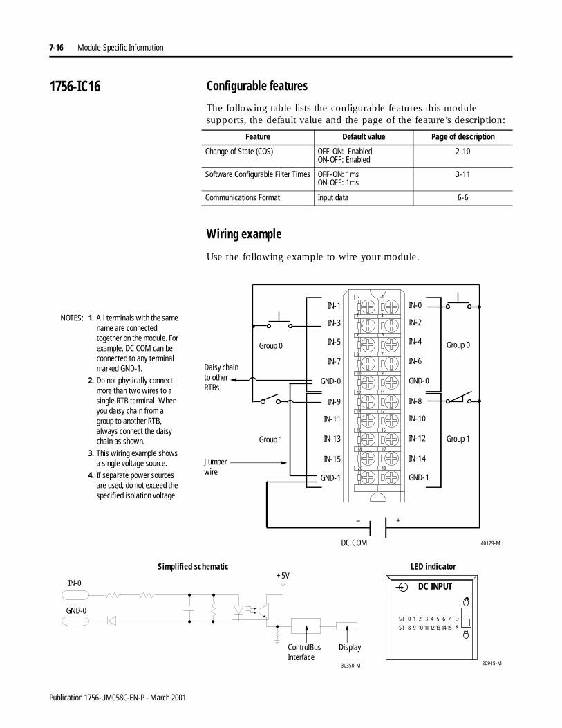
7-16 Module-Specific Information
1756-IC16 Configurable features
The following table lists the configurable features this module supports, the default value and the page of the feature’s description:
Wiring example
Use the following example to wire your module.
Feature Default value Page of description
Change of State (COS) OFF-ON: EnabledON-OFF: Enabled
2-10
Software Configurable Filter Times OFF-ON: 1msON-OFF: 1ms
3-11
Communications Format Input data 6-6
IN-9
IN-11
IN-13
IN-15
GND-1
IN-1
IN-3
IN-5
IN-7
GND-0
IN-8
IN-10
IN-12
IN-14
GND-1
IN-0
IN-2
IN-4
IN-6
GND-0
12
34
56
78
910
1112
1314
1516
1718
1920
1. All terminals with the same name are connected together on the module. For example, DC COM can be connected to any terminal marked GND-1.
2. Do not physically connect more than two wires to a single RTB terminal. When you daisy chain from a group to another RTB, always connect the daisy chain as shown.
3. This wiring example shows a single voltage source.
4. If separate power sources are used, do not exceed the specified isolation voltage.
40179-MDC COM
+–
NOTES:
Daisy chain to other RTBs
Group 0
Group 1
Group 0
Group 1
20945-M
DC INPUT
ST 0 1 2 3 4 5 6 7
ST 8 9 10 11 12 13 14 15
OK
+5V
ControlBusInterface
30350-M
Simplified schematic LED indicator
Display
GND-0
IN-0
Jumper wire
Publication 1756-UM058C-EN-P - March 2001
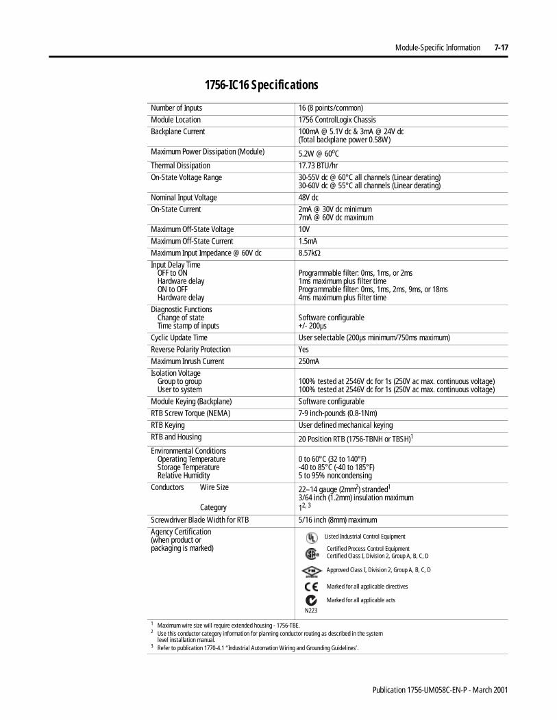
Module-Specific Information 7-17
1756-IC16 Specifications
Number of Inputs 16 (8 points/common)Module Location 1756 ControlLogix ChassisBackplane Current 100mA @ 5.1V dc & 3mA @ 24V dc
(Total backplane power 0.58W)Maximum Power Dissipation (Module) 5.2W @ 60oCThermal Dissipation 17.73 BTU/hrOn-State Voltage Range 30-55V dc @ 60°C all channels (Linear derating)
30-60V dc @ 55°C all channels (Linear derating)Nominal Input Voltage 48V dcOn-State Current 2mA @ 30V dc minimum
7mA @ 60V dc maximumMaximum Off-State Voltage 10VMaximum Off-State Current 1.5mAMaximum Input Impedance @ 60V dc 8.57kΩInput Delay Time
OFF to ONHardware delayON to OFFHardware delay
Programmable filter: 0ms, 1ms, or 2ms1ms maximum plus filter timeProgrammable filter: 0ms, 1ms, 2ms, 9ms, or 18ms4ms maximum plus filter time
Diagnostic FunctionsChange of stateTime stamp of inputs
Software configurable+/- 200µs
Cyclic Update Time User selectable (200µs minimum/750ms maximum)Reverse Polarity Protection YesMaximum Inrush Current 250mAIsolation Voltage
Group to groupUser to system
100% tested at 2546V dc for 1s (250V ac max. continuous voltage)100% tested at 2546V dc for 1s (250V ac max. continuous voltage)
Module Keying (Backplane) Software configurableRTB Screw Torque (NEMA) 7-9 inch-pounds (0.8-1Nm)RTB Keying User defined mechanical keyingRTB and Housing 20 Position RTB (1756-TBNH or TBSH)1
Environmental ConditionsOperating TemperatureStorage TemperatureRelative Humidity
0 to 60°C (32 to 140°F)-40 to 85°C (-40 to 185°F)5 to 95% noncondensing
Conductors Wire Size
Category
22–14 gauge (2mm2) stranded1
3/64 inch (1.2mm) insulation maximum12, 3
Screwdriver Blade Width for RTB 5/16 inch (8mm) maximumAgency Certification(when product orpackaging is marked)
1 Maximum wire size will require extended housing - 1756-TBE.2 Use this conductor category information for planning conductor routing as described in the system
level installation manual.3 Refer to publication 1770-4.1 “Industrial Automation Wiring and Grounding Guidelines’.
Marked for all applicable directives
Approved Class I, Division 2, Group A, B, C, D
Certified Process Control EquipmentCertified Class I, Division 2, Group A, B, C, D
Marked for all applicable acts
N223
Listed Industrial Control Equipment
Publication 1756-UM058C-EN-P - March 2001
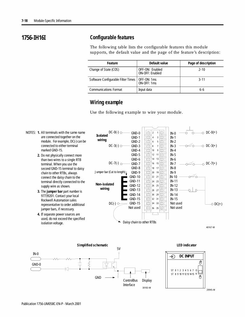
7-18 Module-Specific Information
1756-IH16I Configurable features
The following table lists the configurable features this module supports, the default value and the page of the feature’s description:
Wiring example
Use the following example to wire your module.
Feature Default value Page of description
Change of State (COS) OFF-ON: EnabledON-OFF: Enabled
2-10
Software Configurable Filter Times OFF-ON: 1msON-OFF: 1ms
3-11
Communications Format Input data 6-6
1. All terminals with the same name are connected together on the module. For example, DC(-) can be connected to either terminal marked GND-15.
2. Do not physically connect more than two wires to a single RTB terminal. When you use the second GND-15 terminal to daisy chain to other RTBs, always connect the daisy chain to the terminal directly connected to the supply wire as shown.
3. The jumper bar part number is 97739201. Contact your local Rockwell Automation sales representative to order additional jumper bars, if necessary.
4. If separate power sources areused, do not exceed the specified isolation voltage.
Non-isolated wiring
Isolatedwiring
DC(+)
DC-0(+)
DC-3(-)
DC-0(-)
DC-3(+)
DC(-)
12
34
56
78
910
1112
1314
1516
1718
1920
2122
2324
2526
2728
2930
3132
3334
3536
GND-0
GND-11
GND-1
GND-10
GND-2
GND-9
GND-6
GND-3
GND-7
GND-4
GND-8
GND-5
GND-15GND-14
GND-15
GND-12GND-13
IN-0
IN-8
IN-5
IN-7
IN-9IN-10IN-11IN-12IN-13IN-14IN-15
IN-4
IN-6
IN-1IN-2IN-3
Not usedNot usedNot used
DC-7(-) DC-7(+)
NOTES:
Jumper bar (Cut to length)
Daisy chain to other RTBs40167-M
20945-M
DC INPUT
ST 0 1 2 3 4 5 6 7
ST 8 9 10 1112 13 14 15
OK
ControlBusInterface
5V
30183-M
Simplified schematic LED indicator
Display
GND-0
IN-0
GND
Publication 1756-UM058C-EN-P - March 2001
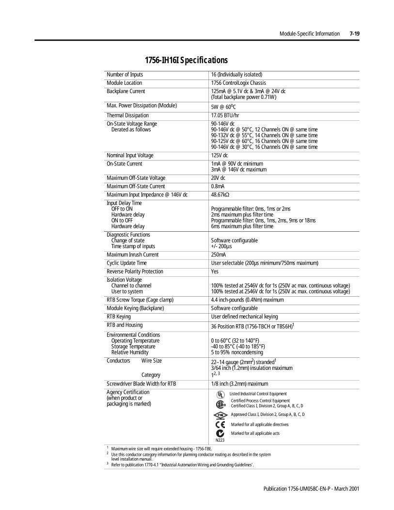
Module-Specific Information 7-19
1756-IH16I Specifications Number of Inputs 16 (Individually isolated)Module Location 1756 ControlLogix ChassisBackplane Current 125mA @ 5.1V dc & 3mA @ 24V dc
(Total backplane power 0.71W)Max. Power Dissipation (Module) 5W @ 60oCThermal Dissipation 17.05 BTU/hrOn-State Voltage Range
Derated as follows90-146V dc90-146V dc @ 50°C, 12 Channels ON @ same time 90-132V dc @ 55°C, 14 Channels ON @ same time90-125V dc @ 60°C, 16 Channels ON @ same time90-146V dc @ 30°C, 16 Channels ON @ same time
Nominal Input Voltage 125V dcOn-State Current 1mA @ 90V dc minimum
3mA @ 146V dc maximumMaximum Off-State Voltage 20V dcMaximum Off-State Current 0.8mAMaximum Input Impedance @ 146V dc 48.67kΩ Input Delay Time
OFF to ONHardware delayON to OFFHardware delay
Programmable filter: 0ms, 1ms or 2ms2ms maximum plus filter timeProgrammable filter: 0ms, 1ms, 2ms, 9ms or 18ms6ms maximum plus filter time
Diagnostic FunctionsChange of stateTime stamp of inputs
Software configurable+/- 200µs
Maximum Inrush Current 250mACyclic Update Time User selectable (200µs minimum/750ms maximum)Reverse Polarity Protection YesIsolation Voltage
Channel to channelUser to system
100% tested at 2546V dc for 1s (250V ac max. continuous voltage)100% tested at 2546V dc for 1s (250V ac max. continuous voltage)
RTB Screw Torque (Cage clamp) 4.4 inch-pounds (0.4Nm) maximumModule Keying (Backplane) Software configurableRTB Keying User defined mechanical keyingRTB and Housing 36 Position RTB (1756-TBCH or TBS6H)1
Environmental ConditionsOperating TemperatureStorage TemperatureRelative Humidity
0 to 60°C (32 to 140°F)-40 to 85°C (-40 to 185°F)5 to 95% noncondensing
Conductors Wire Size
Category
22–14 gauge (2mm2) stranded1
3/64 inch (1.2mm) insulation maximum12, 3
Screwdriver Blade Width for RTB 1/8 inch (3.2mm) maximumAgency Certification(when product orpackaging is marked)
1 Maximum wire size will require extended housing - 1756-TBE.2 Use this conductor category information for planning conductor routing as described in the system
level installation manual.3 Refer to publication 1770-4.1 “Industrial Automation Wiring and Grounding Guidelines’.
Marked for all applicable directives
Approved Class I, Division 2, Group A, B, C, D
Certified Process Control EquipmentCertified Class I, Division 2, Group A, B, C, D
Marked for all applicable acts
N223
Listed Industrial Control Equipment
Publication 1756-UM058C-EN-P - March 2001
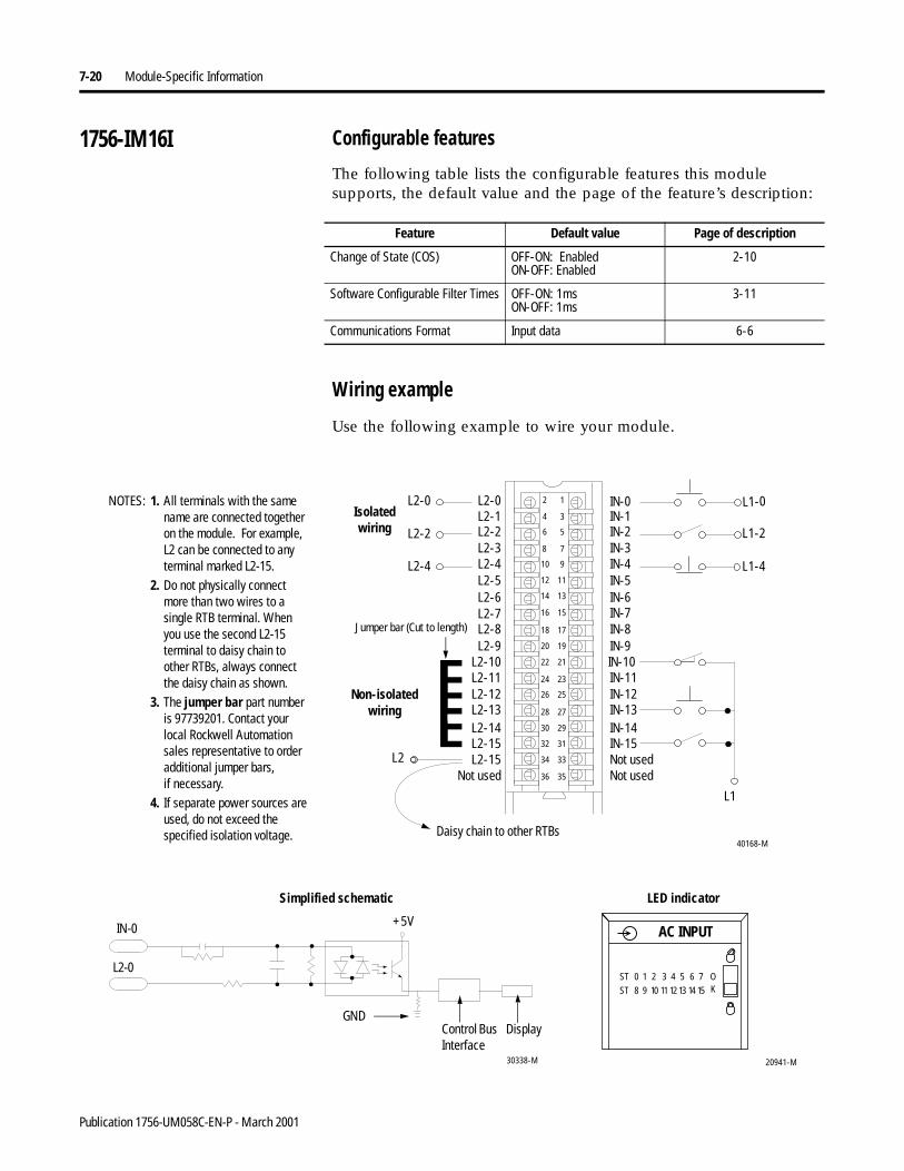
7-20 Module-Specific Information
1756-IM16I Configurable features
The following table lists the configurable features this module supports, the default value and the page of the feature’s description:
Wiring example
Use the following example to wire your module.
Feature Default value Page of description
Change of State (COS) OFF-ON: EnabledON-OFF: Enabled
2-10
Software Configurable Filter Times OFF-ON: 1msON-OFF: 1ms
3-11
Communications Format Input data 6-6
Non-isolated wiring
Isolatedwiring
40168-M
L1
L1-0
L2-2
L2-0
L1-2
L2
1. All terminals with the same name are connected together on the module. For example, L2 can be connected to any terminal marked L2-15.
2. Do not physically connect more than two wires to a single RTB terminal. When you use the second L2-15 terminal to daisy chain to other RTBs, always connect the daisy chain as shown.
3. The jumper bar part number is 97739201. Contact your local Rockwell Automation sales representative to order additional jumper bars,if necessary.
4. If separate power sources areused, do not exceed the specified isolation voltage.
12
34
56
78
910
1112
1314
1516
1718
1920
2122
2324
2526
2728
2930
3132
3334
3536
L2-0
L2-11
L2-1
L2-10
L2-2
L2-9
L2-6
L2-3
L2-7
L2-4
L2-8
L2-5
L2-15L2-14
L2-15
L2-12L2-13
IN-0
IN-8
IN-5
IN-7
IN-9IN-10IN-11IN-12IN-13IN-14IN-15
IN-4
IN-6
IN-1IN-2IN-3
Not usedNot usedNot used
L2-4 L1-4
NOTES:
Jumper bar (Cut to length)
Daisy chain to other RTBs
20941-M
ST 0 1 2 3 4 5 6 7
ST 8 9 10 11 12 13 14 15
OK
AC INPUT+5V
Control Bus Interface
30338-M
Simplified schematic LED indicator
Display
L2-0
IN-0
GND
Publication 1756-UM058C-EN-P - March 2001
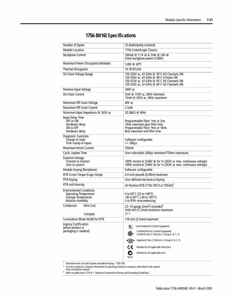
Module-Specific Information 7-21
1756-IM16I Specifications
Number of Inputs 16 (Individually isolated)Module Location 1756 ControlLogix ChassisBackplane Current 100mA @ 5.1V dc & 3mA @ 24V dc
(Total backplane power 0.58W)Maximum Power Dissipation (Module) 5.8W @ 60oCThermal Dissipation 19.78 BTU/hrOn-State Voltage Range 159-265V ac, 47-63Hz @ 30°C All Channels ON
159-265V ac, 47-63Hz @ 40°C 8 Points ON159-253V ac, 47-63Hz @ 45°C All Channels ON159-242V ac, 47-63Hz @ 60°C All Channels ON
Nominal Input Voltage 240V acOn-State Current 5mA @ 159V ac, 60Hz minimum
13mA @ 265V ac, 60Hz maximumMaximum Off-State Voltage 40V acMaximum Off-State Current 2.5mAMaximum Input Impedance @ 265V ac 20.38kΩ @ 60HzInput Delay Time
OFF to ONHardware delayON to OFFHardware delay
Programmable filter: 1ms or 2ms10ms maximum plus filter timeProgrammable filter: 9ms or 18ms8ms maximum and filter time
Diagnostic FunctionsChange of stateTime stamp of inputs
Software configurable+/- 200µs
Maximum Inrush Current 250mACyclic Update Time User selectable (200µs minimum/750ms maximum)Isolation Voltage
Channel to channelUser to system
100% tested at 2546V dc for 1s (265V ac max. continuous voltage)100% tested at 2546V dc for 1s (265V ac max. continuous voltage)
Module Keying (Backplane) Software configurableRTB Screw Torque (Cage clamp) 4.4 inch-pounds (0.4Nm) maximumRTB Keying User defined mechanical keyingRTB and Housing 36 Position RTB (1756-TBCH or TBS6H)1
Environmental ConditionsOperating TemperatureStorage TemperatureRelative Humidity
0 to 60°C (32 to 140°F)-40 to 85°C (-40 to 185°F)5 to 95% noncondensing
Conductors Wire Size
Category
22–14 gauge (2mm2) stranded1
3/64 inch (1.2mm) insulation maximum12, 3
Screwdriver Blade Width for RTB 1/8 inch (3.2mm) maximumAgency Certification(when product orpackaging is marked)
1 Maximum wire size will require extended housing - 1756-TBE.2 Use this conductor category information for planning conductor routing as described in the system
level installation manual.3 Refer to publication 1770-4.1 “Industrial Automation Wiring and Grounding Guidelines’.
Marked for all applicable directives
Approved Class I, Division 2, Group A, B, C, D
Certified Process Control EquipmentCertified Class I, Division 2, Group A, B, C, D
Marked for all applicable acts
N223
Listed Industrial Control Equipment
Publication 1756-UM058C-EN-P - March 2001
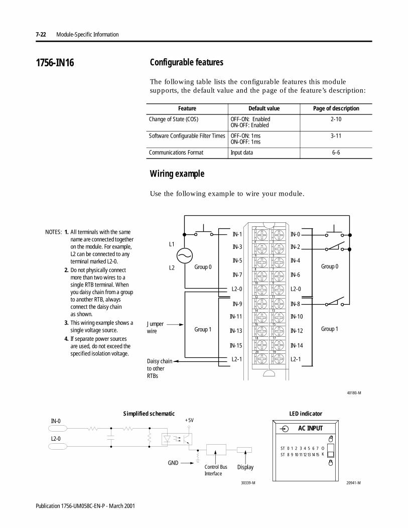
7-22 Module-Specific Information
1756-IN16 Configurable features
The following table lists the configurable features this module supports, the default value and the page of the feature’s description:
Wiring example
Use the following example to wire your module.
Feature Default value Page of description
Change of State (COS) OFF-ON: EnabledON-OFF: Enabled
2-10
Software Configurable Filter Times OFF-ON: 1msON-OFF: 1ms
3-11
Communications Format Input data 6-6
IN-9
IN-11
IN-13
IN-15
L2-1
IN-1
IN-3
IN-5
IN-7
L2-0
IN-8
IN-10
IN-12
IN-14
L2-1
IN-0
IN-2
IN-4
IN-6
L2-0
12
34
56
78
910
1112
1314
1516
1718
1920
40180-M
L1
L2
1. All terminals with the same name are connected together on the module. For example, L2 can be connected to any terminal marked L2-0.
2. Do not physically connect more than two wires to a single RTB terminal. When you daisy chain from a group to another RTB, always connect the daisy chainas shown.
3. This wiring example shows a single voltage source.
4. If separate power sources are used, do not exceed the specified isolation voltage.
NOTES:
Daisy chain to other RTBs
Group 0
Group 1
Group 0
Group 1
20941-M
ST 0 1 2 3 4 5 6 7
ST 8 9 10 11 12 13 14 15
OK
AC INPUT
30339-M
Control Bus Interface
+5VSimplified schematic LED indicator
Display
L2-0
IN-0
GND
Jumper wire
Publication 1756-UM058C-EN-P - March 2001
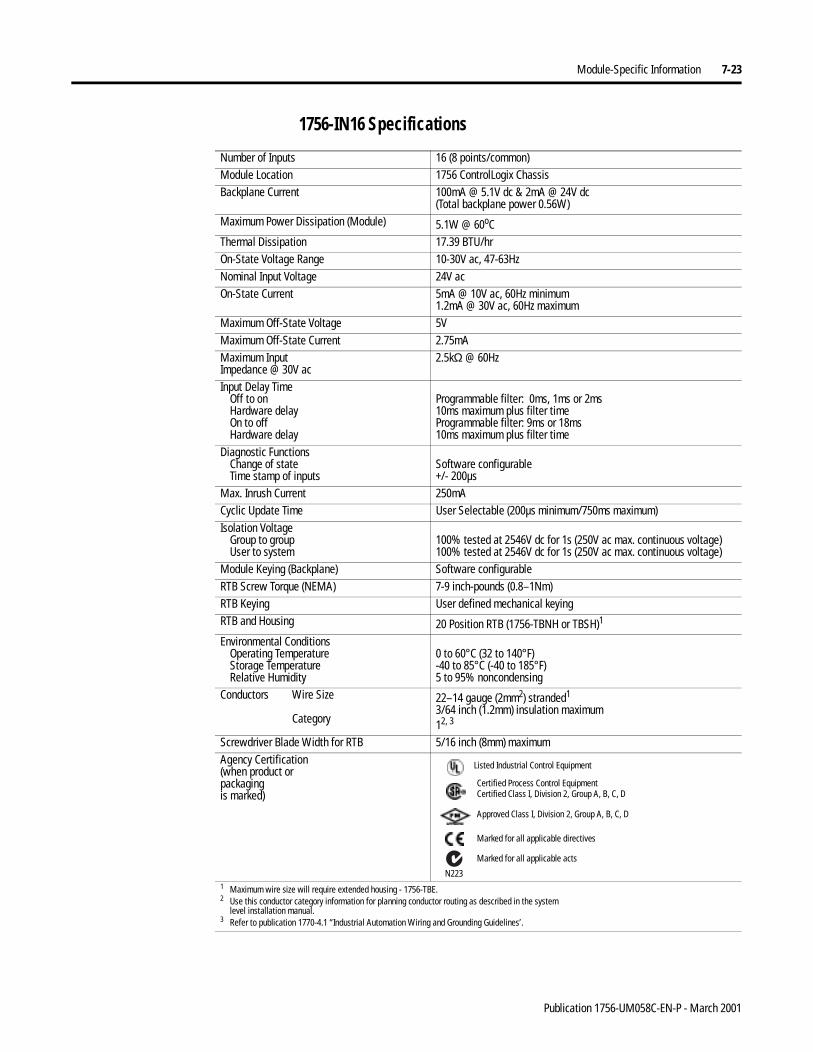
Module-Specific Information 7-23
1756-IN16 Specifications
Number of Inputs 16 (8 points/common)Module Location 1756 ControlLogix ChassisBackplane Current 100mA @ 5.1V dc & 2mA @ 24V dc
(Total backplane power 0.56W)Maximum Power Dissipation (Module) 5.1W @ 60oCThermal Dissipation 17.39 BTU/hrOn-State Voltage Range 10-30V ac, 47-63HzNominal Input Voltage 24V acOn-State Current 5mA @ 10V ac, 60Hz minimum
1.2mA @ 30V ac, 60Hz maximumMaximum Off-State Voltage 5VMaximum Off-State Current 2.75mAMaximum InputImpedance @ 30V ac
2.5kΩ @ 60Hz
Input Delay TimeOff to onHardware delayOn to offHardware delay
Programmable filter: 0ms, 1ms or 2ms10ms maximum plus filter timeProgrammable filter: 9ms or 18ms10ms maximum plus filter time
Diagnostic FunctionsChange of stateTime stamp of inputs
Software configurable+/- 200µs
Max. Inrush Current 250mACyclic Update Time User Selectable (200µs minimum/750ms maximum)Isolation Voltage
Group to groupUser to system
100% tested at 2546V dc for 1s (250V ac max. continuous voltage)100% tested at 2546V dc for 1s (250V ac max. continuous voltage)
Module Keying (Backplane) Software configurableRTB Screw Torque (NEMA) 7-9 inch-pounds (0.8–1Nm) RTB Keying User defined mechanical keyingRTB and Housing 20 Position RTB (1756-TBNH or TBSH)1
Environmental ConditionsOperating TemperatureStorage TemperatureRelative Humidity
0 to 60°C (32 to 140°F)-40 to 85°C (-40 to 185°F)5 to 95% noncondensing
Conductors Wire Size
Category
22–14 gauge (2mm2) stranded1
3/64 inch (1.2mm) insulation maximum12, 3
Screwdriver Blade Width for RTB 5/16 inch (8mm) maximumAgency Certification(when product orpackagingis marked)
1 Maximum wire size will require extended housing - 1756-TBE.2 Use this conductor category information for planning conductor routing as described in the system
level installation manual.3 Refer to publication 1770-4.1 “Industrial Automation Wiring and Grounding Guidelines’.
Marked for all applicable directives
Approved Class I, Division 2, Group A, B, C, D
Certified Process Control EquipmentCertified Class I, Division 2, Group A, B, C, D
Marked for all applicable acts
N223
Listed Industrial Control Equipment
Publication 1756-UM058C-EN-P - March 2001
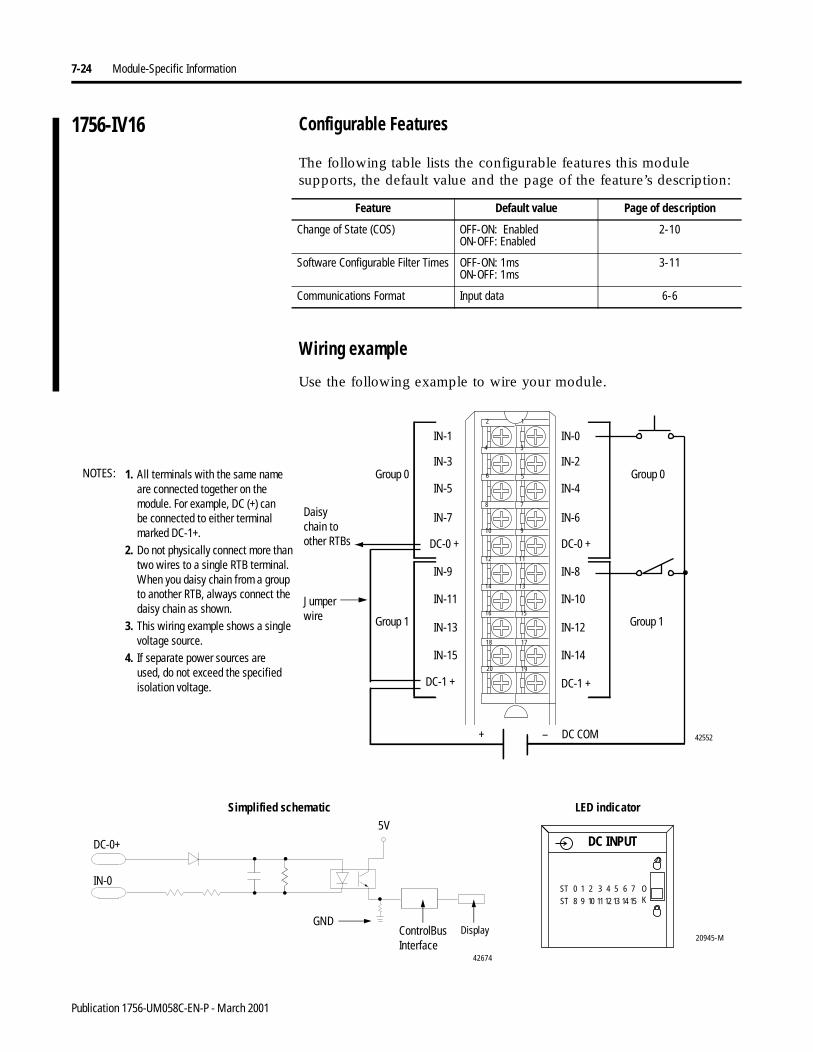
7-24 Module-Specific Information
1756-IV16 Configurable Features
The following table lists the configurable features this module supports, the default value and the page of the feature’s description:
Wiring example
Use the following example to wire your module.
Feature Default value Page of description
Change of State (COS) OFF-ON: EnabledON-OFF: Enabled
2-10
Software Configurable Filter Times OFF-ON: 1msON-OFF: 1ms
3-11
Communications Format Input data 6-6
Daisy chain to other RTBs
ControlBusInterface
5V
42674
20945-M
DC INPUT
ST 0 1 2 3 4 5 6 7
ST 8 9 10 11 12 13 14 15
OK
Simplified schematic LED indicator
DisplayGND
IN-0
DC-0+
Jumper wire
12
34
56
78
910
1112
1314
1516
1718
1920
1. All terminals with the same name are connected together on the module. For example, DC (+) canbe connected to either terminal marked DC-1+.
2. Do not physically connect more than two wires to a single RTB terminal. When you daisy chain from a group to another RTB, always connect the daisy chain as shown.
3. This wiring example shows a single voltage source.
4. If separate power sources areused, do not exceed the specified isolation voltage.
–+
Group 0Group 0
Group 1Group 1
DC COM 42552
IN-0
IN-2
IN-4
IN-6
DC-0 +
IN-8
IN-10
IN-12
IN-14
DC-1 +
IN-1
IN-3
IN-5
IN-7
DC-0 +
IN-9
IN-11
IN-13
IN-15
DC-1 +
NOTES:
Publication 1756-UM058C-EN-P - March 2001
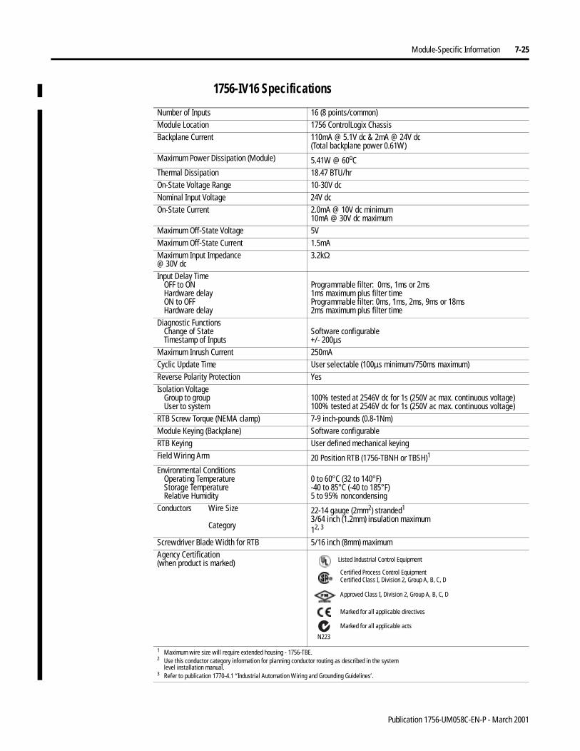
Module-Specific Information 7-25
1756-IV16 Specifications
Number of Inputs 16 (8 points/common)Module Location 1756 ControlLogix ChassisBackplane Current 110mA @ 5.1V dc & 2mA @ 24V dc
(Total backplane power 0.61W)Maximum Power Dissipation (Module) 5.41W @ 60oCThermal Dissipation 18.47 BTU/hrOn-State Voltage Range 10-30V dcNominal Input Voltage 24V dcOn-State Current 2.0mA @ 10V dc minimum
10mA @ 30V dc maximumMaximum Off-State Voltage 5VMaximum Off-State Current 1.5mA Maximum Input Impedance@ 30V dc
3.2kΩ
Input Delay TimeOFF to ONHardware delayON to OFFHardware delay
Programmable filter: 0ms, 1ms or 2ms1ms maximum plus filter timeProgrammable filter: 0ms, 1ms, 2ms, 9ms or 18ms2ms maximum plus filter time
Diagnostic FunctionsChange of StateTimestamp of Inputs
Software configurable+/- 200µs
Maximum Inrush Current 250mACyclic Update Time User selectable (100µs minimum/750ms maximum)Reverse Polarity Protection YesIsolation Voltage
Group to groupUser to system
100% tested at 2546V dc for 1s (250V ac max. continuous voltage)100% tested at 2546V dc for 1s (250V ac max. continuous voltage)
RTB Screw Torque (NEMA clamp) 7-9 inch-pounds (0.8-1Nm)Module Keying (Backplane) Software configurableRTB Keying User defined mechanical keyingField Wiring Arm 20 Position RTB (1756-TBNH or TBSH)1
Environmental ConditionsOperating TemperatureStorage TemperatureRelative Humidity
0 to 60°C (32 to 140°F)-40 to 85°C (-40 to 185°F)5 to 95% noncondensing
Conductors Wire Size
Category
22-14 gauge (2mm2) stranded1
3/64 inch (1.2mm) insulation maximum12, 3
Screwdriver Blade Width for RTB 5/16 inch (8mm) maximumAgency Certification(when product is marked)
1 Maximum wire size will require extended housing - 1756-TBE.2 Use this conductor category information for planning conductor routing as described in the system
level installation manual.3 Refer to publication 1770-4.1 “Industrial Automation Wiring and Grounding Guidelines’.
Marked for all applicable directives
Approved Class I, Division 2, Group A, B, C, D
Certified Process Control EquipmentCertified Class I, Division 2, Group A, B, C, D
Marked for all applicable acts
N223
Listed Industrial Control Equipment
Publication 1756-UM058C-EN-P - March 2001
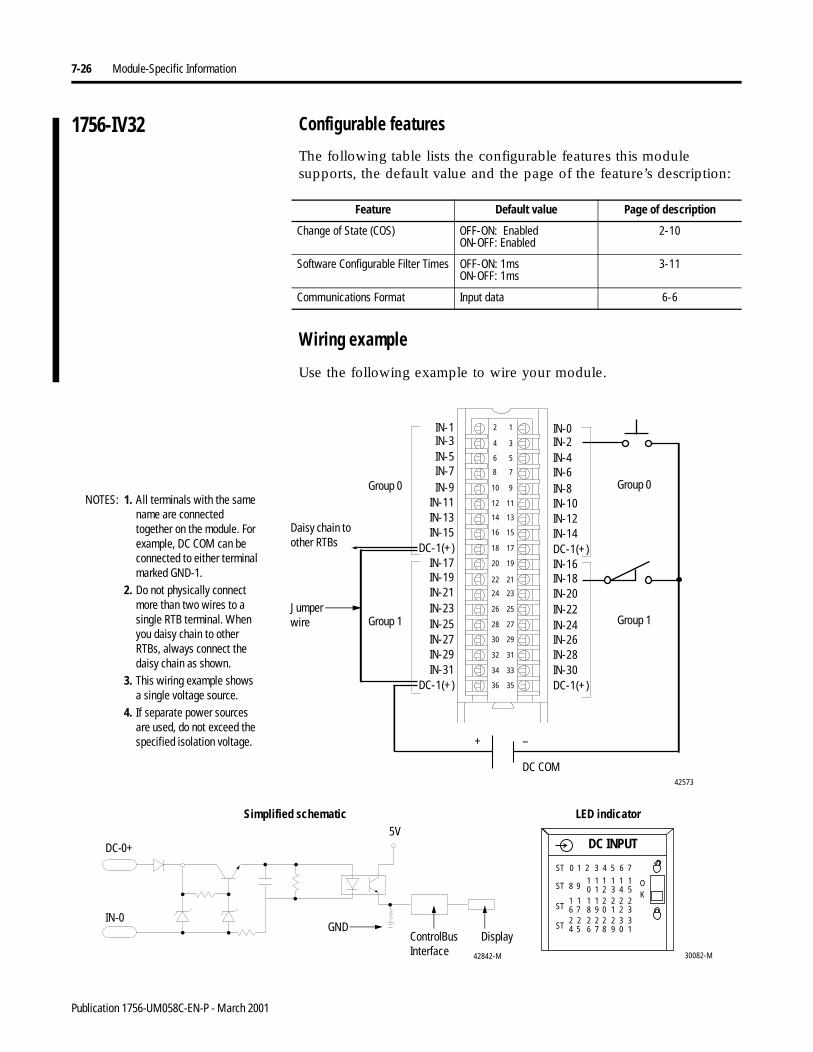
7-26 Module-Specific Information
1756-IV32 Configurable features
The following table lists the configurable features this module supports, the default value and the page of the feature’s description:
Wiring example
Use the following example to wire your module.
Feature Default value Page of description
Change of State (COS) OFF-ON: EnabledON-OFF: Enabled
2-10
Software Configurable Filter Times OFF-ON: 1msON-OFF: 1ms
3-11
Communications Format Input data 6-6
12
34
56
78
910
1112
1314
1516
1718
1920
2122
2324
2526
2728
2930
3132
3334
3536
IN-1
IN-21
IN-3
IN-19
IN-5
IN-17
IN-13
IN-7
IN-15
IN-9
DC-1(+)
IN-11
IN-29IN-27
IN-31
IN-23IN-25
IN-0
DC-1(+)
IN-10
IN-14
IN-16IN-18IN-20IN-22IN-24IN-26IN-28
IN-8
IN-12
IN-2IN-4IN-6
DC-1(+)IN-30DC-1(+)
42573
1. All terminals with the same name are connected together on the module. For example, DC COM can be connected to either terminal marked GND-1.
2. Do not physically connect more than two wires to a single RTB terminal. When you daisy chain to other RTBs, always connect the daisy chain as shown.
3. This wiring example shows a single voltage source.
4. If separate power sources are used, do not exceed the specified isolation voltage. + –
DC COM
NOTES:
Daisy chain to other RTBs
Group 0
Group 1
Group 0
Group 1
30082-M
DC INPUT
OK
ST 0 1 2 3 4 5 6 7
ST 8 910 21 3 4 5
1 1 1 11
ST 6 718 09 1 2 3
1 2 2 221 1
ST 4 526 87 9 0 1
2 2 2 332 2
ControlBusInterface
5V
42842-M
Simplified schematic LED indicator
Display
IN-0GND
DC-0+
Jumper wire
Publication 1756-UM058C-EN-P - March 2001
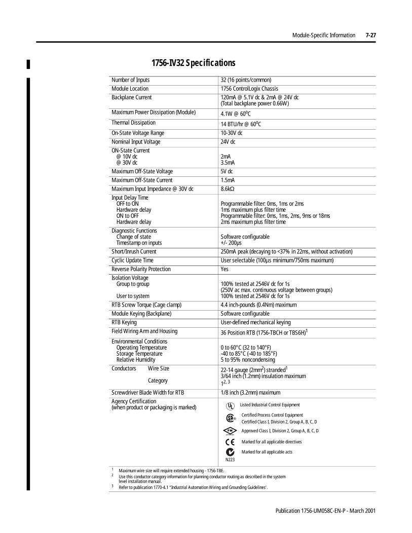
Module-Specific Information 7-27
1756-IV32 Specifications
Number of Inputs 32 (16 points/common)Module Location 1756 ControlLogix ChassisBackplane Current 120mA @ 5.1V dc & 2mA @ 24V dc
(Total backplane power 0.66W)Maximum Power Dissipation (Module) 4.1W @ 60oCThermal Dissipation 14 BTU/hr @ 60oCOn-State Voltage Range 10-30V dcNominal Input Voltage 24V dcON-State Current
@ 10V dc@ 30V dc
2mA3.5mA
Maximum Off-State Voltage 5V dcMaximum Off-State Current 1.5mAMaximum Input Impedance @ 30V dc 8.6kΩInput Delay Time
OFF to ONHardware delayON to OFFHardware delay
Programmable filter: 0ms, 1ms or 2ms1ms maximum plus filter timeProgrammable filter: 0ms, 1ms, 2ms, 9ms or 18ms2ms maximum plus filter time
Diagnostic FunctionsChange of stateTimestamp on inputs
Software configurable+/- 200µs
Short/Inrush Current 250mA peak (decaying to <37% in 22ms, without activation)Cyclic Update Time User selectable (100µs minimum/750ms maximum)Reverse Polarity Protection YesIsolation Voltage
Group to group
User to system
100% tested at 2546V dc for 1s(250V ac max. continuous voltage between groups)100% tested at 2546V dc for 1s
RTB Screw Torque (Cage clamp) 4.4 inch-pounds (0.4Nm) maximumModule Keying (Backplane) Software configurableRTB Keying User-defined mechanical keyingField Wiring Arm and Housing 36 Position RTB (1756-TBCH or TBS6H)1
Environmental ConditionsOperating TemperatureStorage TemperatureRelative Humidity
0 to 60°C (32 to 140°F)-40 to 85°C (-40 to 185°F)5 to 95% noncondensing
Conductors Wire Size
Category
22-14 gauge (2mm2) stranded1
3/64 inch (1.2mm) insulation maximum12, 3
Screwdriver Blade Width for RTB 1/8 inch (3.2mm) maximumAgency Certification(when product or packaging is marked)
1 Maximum wire size will require extended housing - 1756-TBE.2 Use this conductor category information for planning conductor routing as described in the system
level installation manual.3 Refer to publication 1770-4.1 “Industrial Automation Wiring and Grounding Guidelines’.
UL
Marked for all applicable directives
Approved Class I, Division 2, Group A, B, C, D
Certified Process Control EquipmentCertified Class I, Division 2, Group A, B, C, D
Marked for all applicable acts
N223
Listed Industrial Control Equipment
Publication 1756-UM058C-EN-P - March 2001
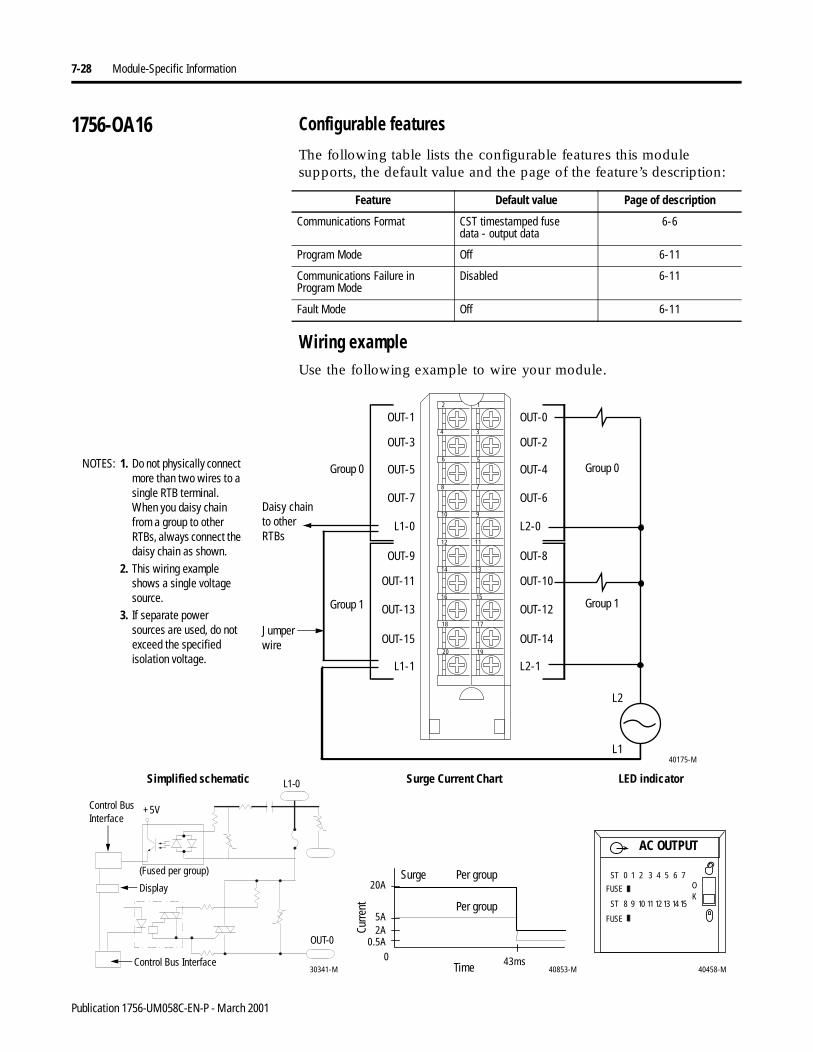
7-28 Module-Specific Information
1756-OA16 Configurable features
The following table lists the configurable features this module supports, the default value and the page of the feature’s description:
Wiring exampleUse the following example to wire your module.
Feature Default value Page of description
Communications Format CST timestamped fusedata - output data
6-6
Program Mode Off 6-11
Communications Failure in Program Mode
Disabled 6-11
Fault Mode Off 6-11
OUT-9
OUT-11
OUT-13
OUT-15
L1-1
OUT-1
OUT-3
OUT-5
OUT-7
L1-0
OUT-8
OUT-10
OUT-12
OUT-14
L2-1
OUT-0
OUT-2
OUT-4
OUT-6
L2-0
12
34
56
78
910
1112
1314
1516
1718
1920
40175-ML1
L2
Daisy chain to other RTBs
1. Do not physically connect more than two wires to a single RTB terminal. When you daisy chain from a group to other RTBs, always connect the daisy chain as shown.
2. This wiring example shows a single voltage source.
3. If separate power sources are used, do not exceed the specified isolation voltage.
NOTES: Group 0
Group 1
Group 0
Group 1
AC OUTPUT
ST 0 1 2 3 4 5 6 7
ST 8 9 10 11 12 13 14 15
OK
FUSE
FUSE
40458-M40853-M
20A
5A
0 43msControl Bus Interface30341-M
2A0.5A
Control Bus Interface
(Fused per group)
+5V
Simplified schematic LED indicator
Per group
Surge Current Chart
Per group
Curre
nt
Time
SurgeDisplay
L1-0
OUT-0
Jumper wire
Publication 1756-UM058C-EN-P - March 2001
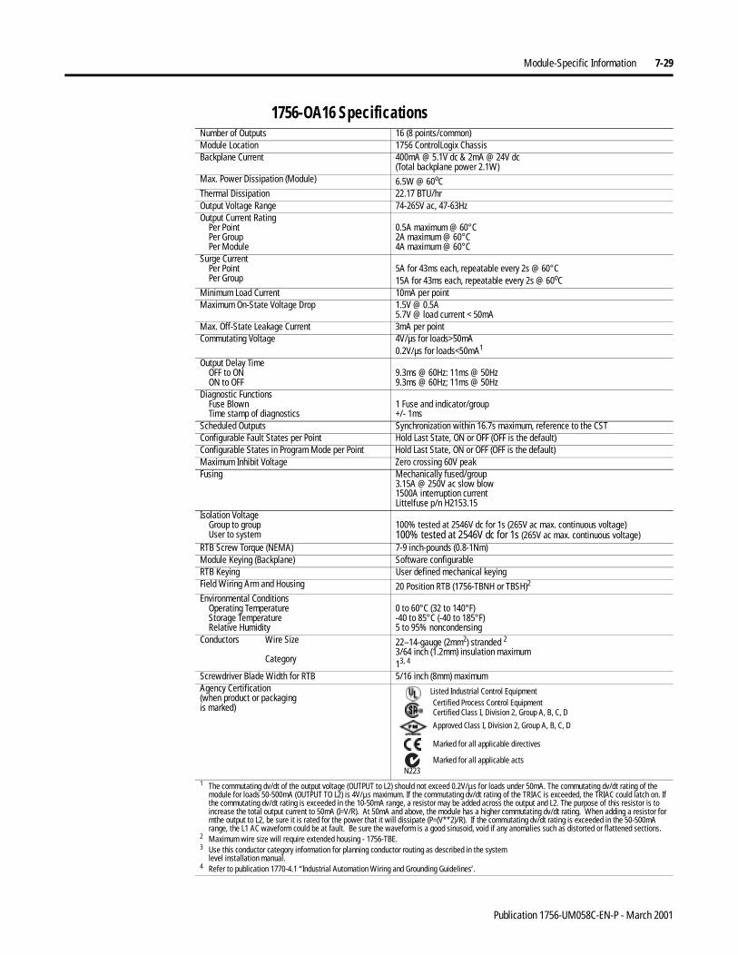
Module-Specific Information 7-29
1756-OA16 Specifications Number of Outputs 16 (8 points/common)Module Location 1756 ControlLogix ChassisBackplane Current 400mA @ 5.1V dc & 2mA @ 24V dc
(Total backplane power 2.1W)Max. Power Dissipation (Module) 6.5W @ 60oCThermal Dissipation 22.17 BTU/hrOutput Voltage Range 74-265V ac, 47-63HzOutput Current Rating
Per PointPer GroupPer Module
0.5A maximum @ 60°C2A maximum @ 60°C4A maximum @ 60°C
Surge Current Per PointPer Group
5A for 43ms each, repeatable every 2s @ 60°C15A for 43ms each, repeatable every 2s @ 60oC
Minimum Load Current 10mA per pointMaximum On-State Voltage Drop 1.5V @ 0.5A
5.7V @ load current < 50mAMax. Off-State Leakage Current 3mA per pointCommutating Voltage 4V/µs for loads>50mA
0.2V/µs for loads<50mA1
Output Delay TimeOFF to ONON to OFF
9.3ms @ 60Hz: 11ms @ 50Hz9.3ms @ 60Hz; 11ms @ 50Hz
Diagnostic FunctionsFuse BlownTime stamp of diagnostics
1 Fuse and indicator/group+/- 1ms
Scheduled Outputs Synchronization within 16.7s maximum, reference to the CSTConfigurable Fault States per Point Hold Last State, ON or OFF (OFF is the default)Configurable States in Program Mode per Point Hold Last State, ON or OFF (OFF is the default)Maximum Inhibit Voltage Zero crossing 60V peakFusing Mechanically fused/group
3.15A @ 250V ac slow blow1500A interruption currentLittelfuse p/n H2153.15
Isolation VoltageGroup to groupUser to system
100% tested at 2546V dc for 1s (265V ac max. continuous voltage)100% tested at 2546V dc for 1s (265V ac max. continuous voltage)
RTB Screw Torque (NEMA) 7-9 inch-pounds (0.8-1Nm)Module Keying (Backplane) Software configurableRTB Keying User defined mechanical keyingField Wiring Arm and Housing 20 Position RTB (1756-TBNH or TBSH)2
Environmental ConditionsOperating TemperatureStorage TemperatureRelative Humidity
0 to 60°C (32 to 140°F)-40 to 85°C (-40 to 185°F)5 to 95% noncondensing
Conductors Wire Size
Category
22–14-gauge (2mm2) stranded 23/64 inch (1.2mm) insulation maximum13, 4
Screwdriver Blade Width for RTB 5/16 inch (8mm) maximumAgency Certification(when product or packagingis marked)
1 The commutating dv/dt of the output voltage (OUTPUT to L2) should not exceed 0.2V/µs for loads under 50mA. The commutating dv/dt rating of the module for loads 50-500mA (OUTPUT TO L2) is 4V/µs maximum. If the commutating dv/dt rating of the TRIAC is exceeded, the TRIAC could latch on. If the commutating dv/dt rating is exceeded in the 10-50mA range, a resistor may be added across the output and L2. The purpose of this resistor is to increase the total output current to 50mA (I=V/R). At 50mA and above, the module has a higher commutating dv/dt rating. When adding a resistor for mthe output to L2, be sure it is rated for the power that it will dissipate (P=(V**2)/R). If the commutating dv/dt rating is exceeded in the 50-500mA range, the L1 AC waveform could be at fault. Be sure the waveform is a good sinusoid, void if any anomalies such as distorted or flattened sections.
2 Maximum wire size will require extended housing - 1756-TBE.3 Use this conductor category information for planning conductor routing as described in the system
level installation manual.4 Refer to publication 1770-4.1 “Industrial Automation Wiring and Grounding Guidelines’.
Marked for all applicable directives
Approved Class I, Division 2, Group A, B, C, D
Certified Process Control EquipmentCertified Class I, Division 2, Group A, B, C, D
Marked for all applicable actsN223
Listed Industrial Control Equipment
Publication 1756-UM058C-EN-P - March 2001
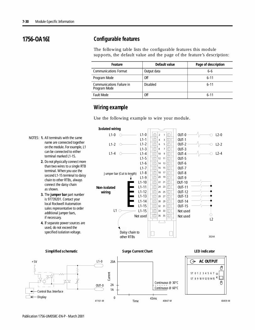
7-30 Module-Specific Information
1756-OA16I Configurable features
The following table lists the configurable features this module supports, the default value and the page of the feature’s description:
Wiring example
Use the following example to wire your module.
Feature Default value Page of description
Communications Format Output data 6-6
Program Mode Off 6-11
Communications Failure in Program Mode
Disabled 6-11
Fault Mode Off 6-11
1. All terminals with the same name are connected together on the module. For example, L1 can be connected to either terminal marked L1-15.
2. Do not physically connect more than two wires to a single RTB terminal. When you use the second L1-15 terminal to daisy chain to other RTBs, always connect the daisy chainas shown.
3. The jumper bar part number is 97739201. Contact your local Rockwell Automation sales representative to order additional jumper bars,if necessary.
4. If separate power sources are used, do not exceed the specified isolation voltage.
12
34
56
78
910
1112
1314
1516
1718
1920
2122
2324
2526
2728
2930
3132
3334
3536
L1-0
L1-11
L1-1
L1-10
L1-2
L1-9
L1-6
L1-3
L1-7
L1-4
L1-8
L1-5
L1-15L1-14
L1-15
L1-12L1-13
OUT-0
OUT-8
OUT-5
OUT-7
OUT-9OUT-10OUT-11OUT-12OUT-13OUT-14OUT-15
OUT-4
OUT-6
OUT-1OUT-2OUT-3
Not usedNot usedNot used
Non-isolated wiring
Isolated wiring
Jumper bar (Cut to length)
L2
L2-0
L1-2
L2-4
L1-0
L2-2
L1-4
L1
30244
Daisy chain to other RTBs
NOTES:
Control Bus Interface
40459-M
ST 0 1 2 3 4 5 6 7
ST 8 9 10 11 12 13 14 15
OK
AC OUTPUT20A
2A
1A
0 43ms40847-M41161-M
+5V
Surge Current Chart
Continuous @ 30°C
Curre
nt
Display
LED indicatorSimplified schematic
OUT-0
L1-0
Continuous @ 60°C
Time
Publication 1756-UM058C-EN-P - March 2001
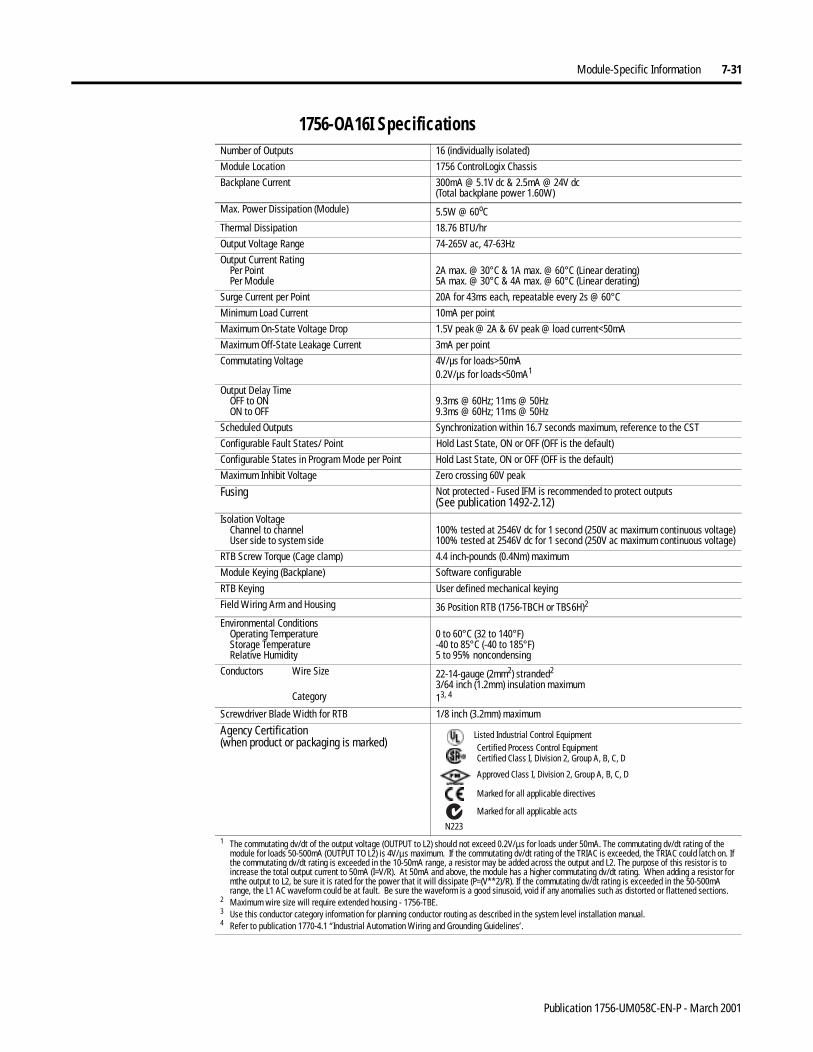
Module-Specific Information 7-31
1756-OA16I Specifications Number of Outputs 16 (individually isolated)
Module Location 1756 ControlLogix Chassis
Backplane Current 300mA @ 5.1V dc & 2.5mA @ 24V dc(Total backplane power 1.60W)
Max. Power Dissipation (Module) 5.5W @ 60oC
Thermal Dissipation 18.76 BTU/hr
Output Voltage Range 74-265V ac, 47-63Hz
Output Current RatingPer PointPer Module
2A max. @ 30°C & 1A max. @ 60°C (Linear derating)5A max. @ 30°C & 4A max. @ 60°C (Linear derating)
Surge Current per Point 20A for 43ms each, repeatable every 2s @ 60°C
Minimum Load Current 10mA per point
Maximum On-State Voltage Drop 1.5V peak @ 2A & 6V peak @ load current<50mA
Maximum Off-State Leakage Current 3mA per point
Commutating Voltage 4V/µs for loads>50mA0.2V/µs for loads<50mA1
Output Delay TimeOFF to ONON to OFF
9.3ms @ 60Hz; 11ms @ 50Hz9.3ms @ 60Hz; 11ms @ 50Hz
Scheduled Outputs Synchronization within 16.7 seconds maximum, reference to the CST
Configurable Fault States/ Point Hold Last State, ON or OFF (OFF is the default)
Configurable States in Program Mode per Point Hold Last State, ON or OFF (OFF is the default)
Maximum Inhibit Voltage Zero crossing 60V peak
Fusing Not protected - Fused IFM is recommended to protect outputs(See publication 1492-2.12)
Isolation VoltageChannel to channelUser side to system side
100% tested at 2546V dc for 1 second (250V ac maximum continuous voltage)100% tested at 2546V dc for 1 second (250V ac maximum continuous voltage)
RTB Screw Torque (Cage clamp) 4.4 inch-pounds (0.4Nm) maximum
Module Keying (Backplane) Software configurable
RTB Keying User defined mechanical keying
Field Wiring Arm and Housing 36 Position RTB (1756-TBCH or TBS6H)2
Environmental ConditionsOperating TemperatureStorage TemperatureRelative Humidity
0 to 60°C (32 to 140°F)-40 to 85°C (-40 to 185°F)5 to 95% noncondensing
Conductors Wire Size
Category
22-14-gauge (2mm2) stranded2
3/64 inch (1.2mm) insulation maximum13, 4
Screwdriver Blade Width for RTB 1/8 inch (3.2mm) maximum
Agency Certification(when product or packaging is marked)
1 The commutating dv/dt of the output voltage (OUTPUT to L2) should not exceed 0.2V/µs for loads under 50mA. The commutating dv/dt rating of the module for loads 50-500mA (OUTPUT TO L2) is 4V/µs maximum. If the commutating dv/dt rating of the TRIAC is exceeded, the TRIAC could latch on. If the commutating dv/dt rating is exceeded in the 10-50mA range, a resistor may be added across the output and L2. The purpose of this resistor is to increase the total output current to 50mA (I=V/R). At 50mA and above, the module has a higher commutating dv/dt rating. When adding a resistor for mthe output to L2, be sure it is rated for the power that it will dissipate (P=(V**2)/R). If the commutating dv/dt rating is exceeded in the 50-500mA range, the L1 AC waveform could be at fault. Be sure the waveform is a good sinusoid, void if any anomalies such as distorted or flattened sections.
2 Maximum wire size will require extended housing - 1756-TBE.3 Use this conductor category information for planning conductor routing as described in the system level installation manual.4 Refer to publication 1770-4.1 “Industrial Automation Wiring and Grounding Guidelines’.
Marked for all applicable directives
Approved Class I, Division 2, Group A, B, C, D
Certified Process Control EquipmentCertified Class I, Division 2, Group A, B, C, D
Marked for all applicable acts
N223
Listed Industrial Control Equipment
Publication 1756-UM058C-EN-P - March 2001
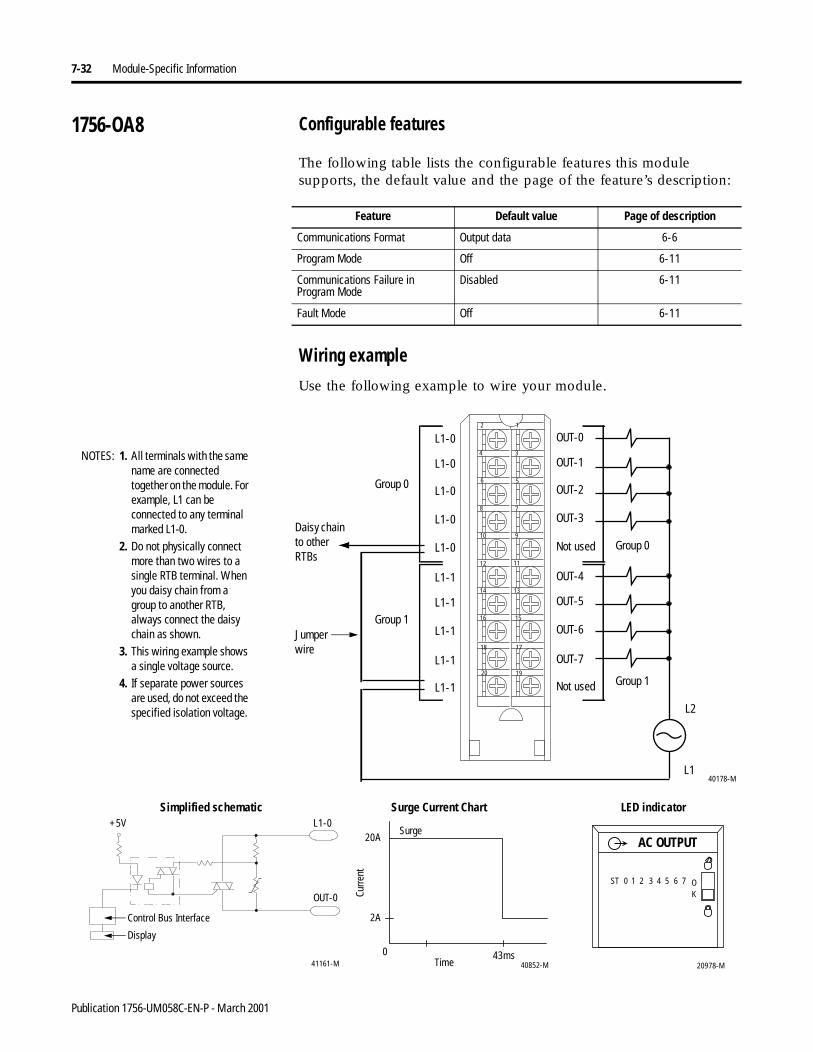
7-32 Module-Specific Information
1756-OA8 Configurable features
The following table lists the configurable features this module supports, the default value and the page of the feature’s description:
Wiring example
Use the following example to wire your module.
Feature Default value Page of description
Communications Format Output data 6-6
Program Mode Off 6-11
Communications Failure in Program Mode
Disabled 6-11
Fault Mode Off 6-11
L1-1
L1-1
L1-1
L1-1
L1-1
L1-0
L1-0
L1-0
L1-0
L1-0
OUT-4
OUT-5
OUT-6
OUT-7
Not used
OUT-0
OUT-1
OUT-2
OUT-3
Not used
12
34
56
78
910
1112
1314
1516
1718
1920
L2
40178-ML1
1. All terminals with the same name are connected together on the module. For example, L1 can be connected to any terminal marked L1-0.
2. Do not physically connect more than two wires to a single RTB terminal. When you daisy chain from a group to another RTB, always connect the daisy chain as shown.
3. This wiring example shows a single voltage source.
4. If separate power sources are used, do not exceed the specified isolation voltage.
Daisy chain to other RTBs
NOTES:
Group 0
Group 1
Group 0
Group 1
20978-M
ST 0 1 2 3 4 5 6 7 OK
AC OUTPUT20A
2A
0 43ms40852-M
Control Bus Interface
41161-M
+5V
Surge Current Chart
Curre
nt
Display
LED indicatorSimplified schematic
OUT-0
L1-0
Time
Surge
Jumper wire
Publication 1756-UM058C-EN-P - March 2001
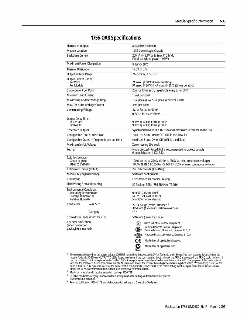
Module-Specific Information 7-33
1756-OA8 Specifications Number of Outputs 8 (4 points/common)
Module Location 1756 ControlLogix Chassis
Backplane Current 200mA @ 5.1V dc & 2mA @ 24V dc(Total backplane power 1.07W)
Maximum Power Dissipation 5.1W @ 60oC
Thermal Dissipation 17.39 BTU/hr
Output Voltage Range 74-265V ac, 47-63Hz
Output Current RatingPer PointPer Module
2A max. @ 60°C (Linear derating)5A max. @ 30°C & 4A max. @ 60°C (Linear derating)
Surge Current per Point 20A for 43ms each, repeatable every 2s @ 60°C
Minimum Load Current 10mA per point
Maximum On-State Voltage Drop 1.5V peak @ 2A & 6V peak @ current<50mA
Max. Off-State Leakage Current 3mA per point
Commutating Voltage 4V/µs for loads>50mA0.2V/µs for loads<50mA1
Output Delay TimeOFF to ONON to OFF
9.3ms @ 60Hz; 11ms @ 50Hz9.3ms @ 60Hz; 11ms @ 50Hz
Scheduled Outputs Synchronization within 16.7 seconds maximum, reference to the CST
Configurable Fault States/Point Hold Last State, ON or OFF (OFF is the default)
Configurable States in Program Mode per Point Hold Last State, ON or OFF (OFF is the default)
Maximum Inhibit Voltage Zero crossing 60V peak
Fusing Not protected - Fused IFM is recommended to protect outputs(See publication 1492-2.12)
Isolation VoltageGroup to groupUser to system
100% tested at 2546V dc for 1s (265V ac max. continuous voltage)100% tested at 2546V dc for 1s (265V ac max. continuous voltage)
RTB Screw Torque (NEMA) 7-9 inch-pounds (0.8–1Nm)
Module Keying (Backplane) Software configurable
RTB Keying User defined mechanical keying
Field Wiring Arm and Housing 20 Position RTB (1756-TBNH or TBSH)2
Environmental ConditionsOperating TemperatureStorage TemperatureRelative Humidity
0 to 60°C (32 to 140°F)-40 to 85°C (-40 to 185°F)5 to 95% noncondensing
Conductors Wire Size
Category
22-14-gauge (2mm2) stranded 23/64 inch (1.2mm) insulation maximum13, 4
Screwdriver Blade Width for RTB 5/16 inch (8mm) maximum
Agency Certification(when product orpackaging is marked)
1 The commutating dv/dt of the output voltage (OUTPUT to L2) should not exceed 0.2V/µs for loads under 50mA. The commutating dv/dt rating of the module for loads 50-500mA (OUTPUT TO L2) is 4V/µs maximum. If the commutating dv/dt rating of the TRIAC is exceeded, the TRIAC could latch on. If the commutating dv/dt rating is exceeded in the 10-50mA range, a resistor may be added across the output and L2. The purpose of this resistor is to increase the total output current to 50mA (I=V/R). At 50mA and above, the module has a higher commutating dv/dt rating. When adding a resistor for mthe output to L2, be sure it is rated for the power that it will dissipate (P=(V**2)/R). If the commutating dv/dt rating is exceeded in the 50-500mA range, the L1 AC waveform could be at fault. Be sure the waveform is a good.
2 Maximum wire size will require extended housing - 1756-TBE.3 Use this conductor category information for planning conductor routing as described in the system
level installation manual.4 Refer to publication 1770-4.1 “Industrial Automation Wiring and Grounding Guidelines’.
Marked for all applicable directives
Approved Class I, Division 2, Group A, B, C, D
Certified Process Control EquipmentCertified Class I, Division 2, Group A, B, C, D
Marked for all applicable actsN223
Listed Industrial Control Equipment
Publication 1756-UM058C-EN-P - March 2001
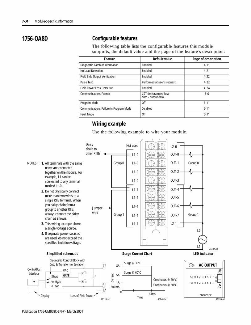
7-34 Module-Specific Information
1756-OA8D Configurable featuresThe following table lists the configurable features this module supports, the default value and the page of the feature’s description:
Wiring exampleUse the following example to wire your module.
Feature Default value Page of description
Diagnostic Latch of Information Enabled 4-11
No Load Detection Enabled 4-21
Field Side Output Verification Enabled 4-22
Pulse Test Performed at user’s request 4-22
Field Power Loss Detection Enabled 4-24
Communications Format CST timestamped fusedata - output data
6-6
Program Mode Off 6-11
Communications Failure in Program Mode Disabled 6-11
Fault Mode Off 6-11
1. All terminals with the same name are connected together on the module. For example, L1 can be connected to any terminal marked L1-0.
2. Do not physically connect more than two wires to a single RTB terminal. When you daisy chain from a group to another RTB, always connect the daisy chain as shown.
3. This wiring example shows a single voltage source.
4. If separate power sources are used, do not exceed the specified isolation voltage.
L1-1
L1-1
L1-1
L1-1
L1-1
L1-0
L1-0
L1-0
L1-0
OUT-4
OUT-5
OUT-6
OUT-7
L2-1
L2-0
OUT-0
OUT-1
OUT-2
OUT-3
12
34
56
78
910
1112
1314
1516
1718
1920
L1
L2
40185-M
Not usedDaisy chain to other RTBs
NOTES: Group 0
Group 1
Group 0
Group 1
20935-M
DIAGNOSTIC
ST 0 1 2 3 4 5 6 7 OK
AC OUTPUT
FLT 0 1 2 3 4 5 6 7
8A
5A
1A500mA
0 43ms
40848-M
ControlBus Interface
Diagnostic Control Block with Opto & Transformer Isolation
41118-M
Surge Current Chart
Continuous @ 30°CCurre
nt
Display
LED indicatorSimplified schematic
OUT
L1
Continuous @ 60°C
Time
Surge @ 30°C
Surge @ 60°C
Loss of Field Power
Short
Verify/No Load
VAC
GATE
L2
Jumper wire
Publication 1756-UM058C-EN-P - March 2001
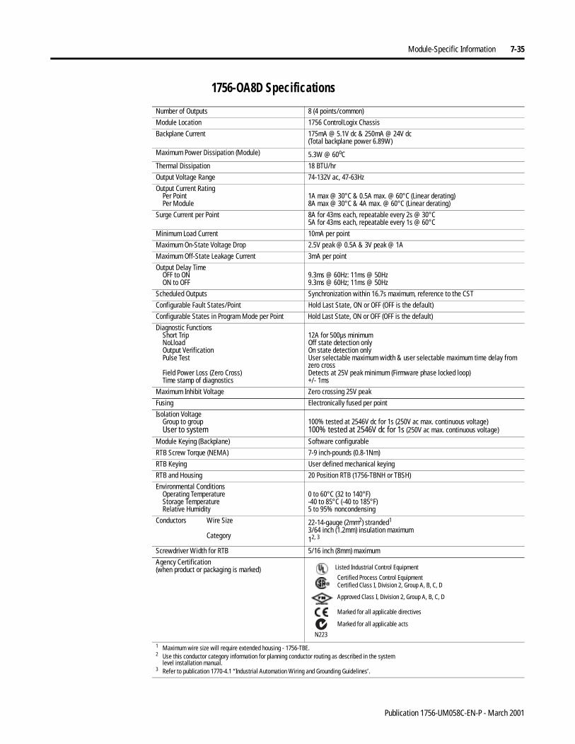
Module-Specific Information 7-35
1756-OA8D Specifications
Number of Outputs 8 (4 points/common)
Module Location 1756 ControlLogix Chassis
Backplane Current 175mA @ 5.1V dc & 250mA @ 24V dc(Total backplane power 6.89W)
Maximum Power Dissipation (Module) 5.3W @ 60oC
Thermal Dissipation 18 BTU/hr
Output Voltage Range 74-132V ac, 47-63Hz
Output Current RatingPer PointPer Module
1A max @ 30°C & 0.5A max. @ 60°C (Linear derating)8A max @ 30°C & 4A max. @ 60°C (Linear derating)
Surge Current per Point 8A for 43ms each, repeatable every 2s @ 30°C5A for 43ms each, repeatable every 1s @ 60°C
Minimum Load Current 10mA per point
Maximum On-State Voltage Drop 2.5V peak @ 0.5A & 3V peak @ 1A
Maximum Off-State Leakage Current 3mA per point
Output Delay TimeOFF to ONON to OFF
9.3ms @ 60Hz: 11ms @ 50Hz9.3ms @ 60Hz; 11ms @ 50Hz
Scheduled Outputs Synchronization within 16.7s maximum, reference to the CST
Configurable Fault States/Point Hold Last State, ON or OFF (OFF is the default)
Configurable States in Program Mode per Point Hold Last State, ON or OFF (OFF is the default)
Diagnostic FunctionsShort TripNoLloadOutput VerificationPulse Test
Field Power Loss (Zero Cross)Time stamp of diagnostics
12A for 500µs minimumOff state detection onlyOn state detection onlyUser selectable maximum width & user selectable maximum time delay from zero crossDetects at 25V peak minimum (Firmware phase locked loop)+/- 1ms
Maximum Inhibit Voltage Zero crossing 25V peak
Fusing Electronically fused per point
Isolation VoltageGroup to groupUser to system
100% tested at 2546V dc for 1s (250V ac max. continuous voltage)100% tested at 2546V dc for 1s (250V ac max. continuous voltage)
Module Keying (Backplane) Software configurable
RTB Screw Torque (NEMA) 7-9 inch-pounds (0.8-1Nm)
RTB Keying User defined mechanical keying
RTB and Housing 20 Position RTB (1756-TBNH or TBSH)
Environmental ConditionsOperating TemperatureStorage TemperatureRelative Humidity
0 to 60°C (32 to 140°F)-40 to 85°C (-40 to 185°F)5 to 95% noncondensing
Conductors Wire Size
Category
22-14-gauge (2mm2) stranded1
3/64 inch (1.2mm) insulation maximum12, 3
Screwdriver Width for RTB 5/16 inch (8mm) maximum
Agency Certification(when product or packaging is marked)
1 Maximum wire size will require extended housing - 1756-TBE.2 Use this conductor category information for planning conductor routing as described in the system
level installation manual.3 Refer to publication 1770-4.1 “Industrial Automation Wiring and Grounding Guidelines’.
Marked for all applicable directives
Approved Class I, Division 2, Group A, B, C, D
Certified Process Control EquipmentCertified Class I, Division 2, Group A, B, C, D
Marked for all applicable acts
N223
Listed Industrial Control Equipment
Publication 1756-UM058C-EN-P - March 2001
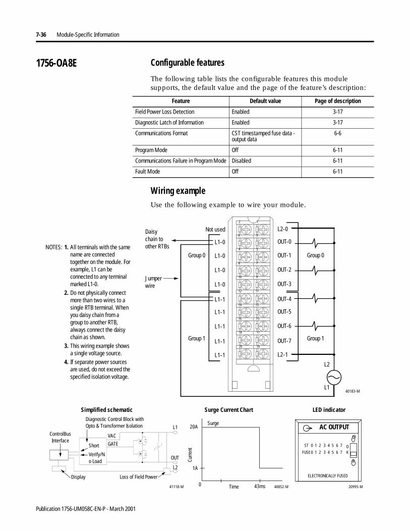
7-36 Module-Specific Information
1756-OA8E Configurable features
The following table lists the configurable features this module supports, the default value and the page of the feature’s description:
Wiring exampleUse the following example to wire your module.
Feature Default value Page of description
Field Power Loss Detection Enabled 3-17
Diagnostic Latch of Information Enabled 3-17
Communications Format CST timestamped fuse data - output data
6-6
Program Mode Off 6-11
Communications Failure in Program Mode Disabled 6-11
Fault Mode Off 6-11
L1-1
L1-1
L1-1
L1-1
L1-1
Not used
L1-0
L1-0
L1-0
L1-0
OUT-4
OUT-5
OUT-6
OUT-7
L2-1
L2-0
OUT-0
OUT-1
OUT-2
OUT-3
12
34
56
78
910
1112
1314
1516
1718
1920
L1
L2
40183-M
1. All terminals with the same name are connected together on the module. For example, L1 can be connected to any terminal marked L1-0.
2. Do not physically connect more than two wires to a single RTB terminal. When you daisy chain from a group to another RTB, always connect the daisy chain as shown.
3. This wiring example shows a single voltage source.
4. If separate power sources are used, do not exceed the specified isolation voltage.
Daisy chain to other RTBsNOTES:
Group 0
Group 1
Group 0
Group 1
20995-M
ST 0 1 2 3 4 5 6 7
FUSE0 1 2 3 4 5 6 7OK
AC OUTPUT
ELECTRONICALLY FUSED
20A
0 43ms 40852-M
1A
ControlBus Interface
Diagnostic Control Block with Opto & Transformer Isolation
41118-M
Surge Current Chart
Curre
nt
Display
LED indicatorSimplified schematic
OUT
L1
Time
Surge
Loss of Field Power
Short
Verify/No Load
VAC
GATE
L2
Jumper wire
Publication 1756-UM058C-EN-P - March 2001
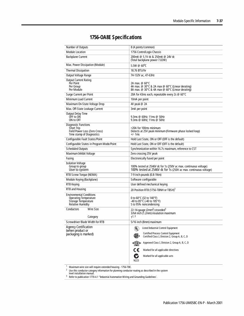
Module-Specific Information 7-37
1756-OA8E Specifications
Number of Outputs 8 (4 points/common)
Module Location 1756 ControlLogix Chassis
Backplane Current 200mA @ 5.1V dc & 250mA @ 24V dc(Total backplane power 7.02W)
Max. Power Dissipation (Module) 5.5W @ 60oC
Thermal Dissipation 18.76 BTU/hr
Output Voltage Range 74-132V ac, 47-63Hz
Output Current RatingPer PointPer GroupPer Module
2A max. @ 60°C4A max. @ 30°C & 2A max @ 60°C (Linear derating)8A max. @ 30°C & 4A max @ 60°C (Linear derating)
Surge Current per Point 20A for 43ms each, repeatable every 2s @ 60°C
Minimum Load Current 10mA per point
Maximum On-State Voltage Drop 4V peak @ 2A
Max. Off-State Leakage Current 3mA per point
Output Delay TimeOFF to ONON to OFF
9.3ms @ 60Hz; 11ms @ 50Hz9.3ms @ 60Hz; 11ms @ 50Hz
Diagnostic FunctionsShort TripField Power Loss (Zero Cross)Time stamp of Diagnostics
>20A for 100ms minimumDetects at 25V peak minimum (Firmware phase locked loop)+/- 1ms
Configurable Fault States/Point Hold Last State, ON or OFF (OFF is the default)
Configurable States in Program Mode/Point Hold Last State, ON or OFF (OFF is the default)
Scheduled Outputs Synchronization within 16.7s maximum, reference to CST
Maximum Inhibit Voltage Zero crossing 25V peak
Fusing Electronically fused per point
Isolation VoltageGroup to groupUser to system
100% tested at 2546V dc for 1s (250V ac max. continuous voltage)100% tested at 2546V dc for 1s (250V ac max. continuous voltage)
RTB Screw Torque (NEMA) 7-9 inch-pounds (0.8-1Nm)
Module Keying (Backplane) Software configurable
RTB Keying User defined mechanical keying
RTB and Housing 20 Position RTB (1756-TBNH or TBSH)1
Environmental ConditionsOperating TemperatureStorage TemperatureRelative Humidity
0 to 60°C (32 to 140°F)-40 to 85°C (-40 to 185°F)5 to 95% noncondensing
Conductors Wire Size
Category
22-14-gauge (2mm2) stranded1
3/64 inch (1.2mm) insulation maximum12, 3
Screwdriver Blade Width for RTB 5/16 inch (8mm) maximum
Agency Certification(when product orpackaging is marked)
1 Maximum wire size will require extended housing - 1756-TBE.2 Use this conductor category information for planning conductor routing as described in the system
level installation manual.3 Refer to publication 1770-4.1 “Industrial Automation Wiring and Grounding Guidelines’.
Marked for all applicable directives
Approved Class I, Division 2, Group A, B, C, D
Certified Process Control EquipmentCertified Class I, Division 2, Group A, B, C, D
Marked for all applicable acts
N223
Listed Industrial Control Equipment
Publication 1756-UM058C-EN-P - March 2001
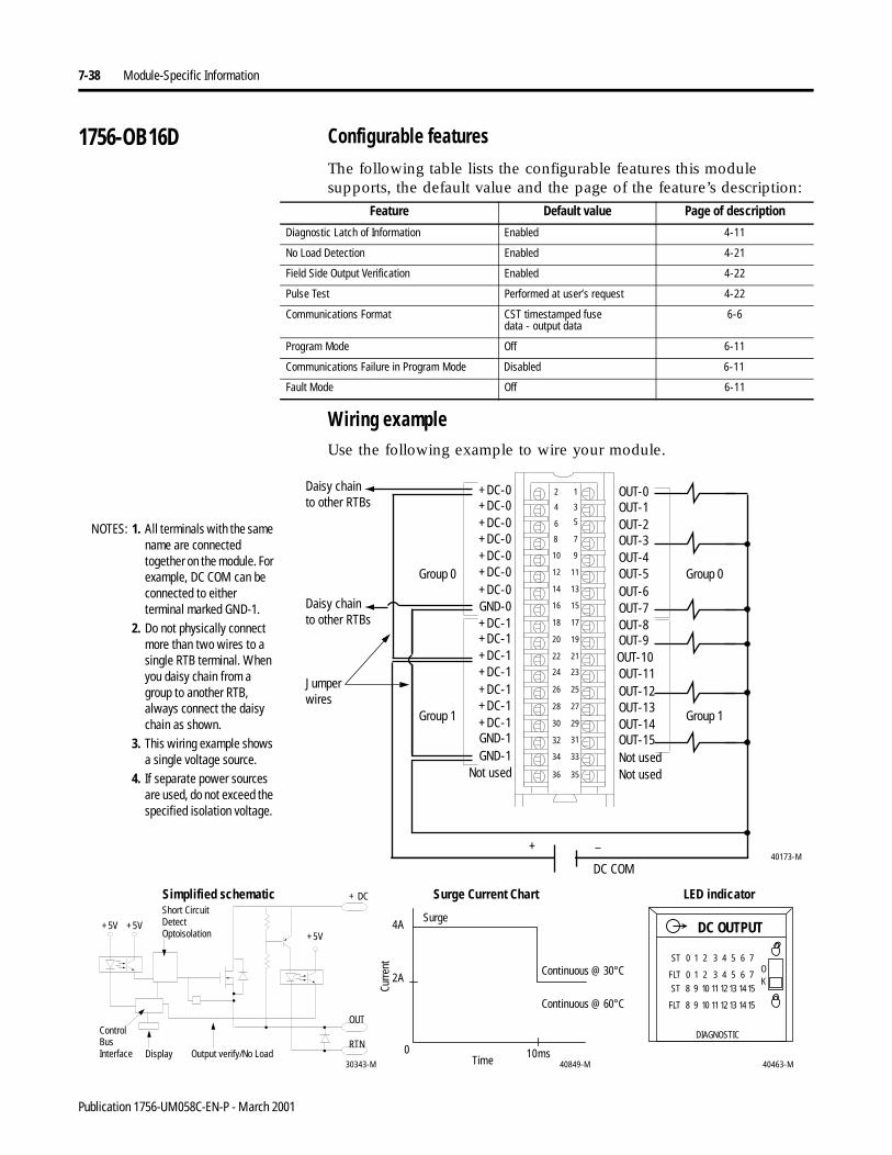
7-38 Module-Specific Information
1756-OB16D Configurable featuresThe following table lists the configurable features this module supports, the default value and the page of the feature’s description:
Wiring exampleUse the following example to wire your module.
Feature Default value Page of description
Diagnostic Latch of Information Enabled 4-11
No Load Detection Enabled 4-21
Field Side Output Verification Enabled 4-22
Pulse Test Performed at user’s request 4-22
Communications Format CST timestamped fusedata - output data
6-6
Program Mode Off 6-11
Communications Failure in Program Mode Disabled 6-11
Fault Mode Off 6-11
12
34
56
78
910
1112
1314
1516
1718
1920
2122
2324
2526
2728
2930
3132
3334
3536
+DC-0
+DC-1
+DC-0
+DC-1
+DC-0
+DC-1
+DC-0
+DC-0
GND-0
+DC-0
+DC-1
+DC-0
GND-1+DC-1
GND-1
+DC-1+DC-1
OUT-0
OUT-8
OUT-5
OUT-7
OUT-9OUT-10OUT-11OUT-12OUT-13OUT-14OUT-15
OUT-4
OUT-6
OUT-1OUT-2OUT-3
Not usedNot usedNot used
40173-M+ –
DC COM
1. All terminals with the same name are connected together on the module. For example, DC COM can be connected to either terminal marked GND-1.
2. Do not physically connect more than two wires to a single RTB terminal. When you daisy chain from a group to another RTB, always connect the daisy chain as shown.
3. This wiring example shows a single voltage source.
4. If separate power sources are used, do not exceed the specified isolation voltage.
Daisy chain to other RTBs
NOTES:
Group 0
Group 1
Group 0
Group 1
40463-M
ST 0 1 2 3 4 5 6 7
FLT 0 1 2 3 4 5 6 7
DIAGNOSTIC
ST 8 9 10 11 12 13 1415
FLT 8 9 10 11 12 13 1415
DC OUTPUT
OK
4A
2A
0 10ms40849-M30343-M
Control BusInterface Display
+5V
Short Circuit Detect Optoisolation
+5V
+ DC
OUT
RTNOutput verify/No Load
Surge Current Chart
Continuous @ 30°C
Curre
nt
LED indicatorSimplified schematic
Continuous @ 60°C
Time
Surge
+5V
Daisy chain to other RTBs
Jumper wires
Publication 1756-UM058C-EN-P - March 2001
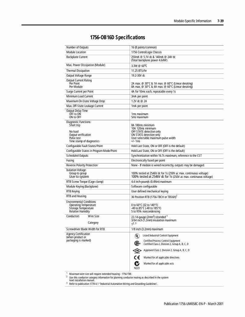
Module-Specific Information 7-39
1756-OB16D Specifications
Number of Outputs 16 (8 points/common)
Module Location 1756 ControlLogix Chassis
Backplane Current 250mA @ 5.1V dc & 140mA @ 24V dc(Total backplane power 4.64W)
Max. Power Dissipation (Module) 3.3W @ 60oC
Thermal Dissipation 11.25 BTU/hr
Output Voltage Range 19.2-30V dc
Output Current RatingPer PointPer Module
2A max. @ 30°C & 1A max. @ 60°C (Linear derating)8A max. @ 30°C & 4A max. @ 60°C (Linear derating)
Surge Current per Point 4A for 10ms each, repeatable every 1s
Minimum Load Current 3mA per point
Maximum On-State Voltage Drop 1.2V dc @ 2A
Max. Off-State Leakage Current 1mA per point
Output Delay TimeOFF to ONON to OFF
1ms maximum5ms maximum
Diagnostic Functions:Short trip
No loadOutput verificationPulse testTime stamp of diagnostics
8A 180ms minimum10A 120ms minimumOFF STATE detection onlyON STATE detection onlyUser selectable maximum pulse width+/- 1ms
Configurable Fault States/Point Hold Last State, ON or OFF (OFF is the default)
Configurable States in Program Mode/Point Hold Last State, ON or OFF (OFF is the default)
Scheduled Outputs Synchronization within 16.7s maximum, reference to the CST
Fusing Electronically fused per point
Reverse Polarity Protection None - If module is wired incorrectly, outputs may be damaged.
Isolation VoltageGroup to groupUser to system
100% tested at 2546V dc for 1s (250V ac max. continuous voltage)100% tested at 2546V dc for 1s (250V ac max. continuous voltage)
RTB Screw Torque (Cage clamp) 4.4 inch-pounds (0.4Nm) maximum
Module Keying (Backplane) Software configurable
RTB Keying User defined mechanical keying
RTB and Housing 36 Position RTB (1756-TBCH or TBS6H)1
Environmental ConditionsOperating TemperatureStorage TemperatureRelative Humidity
0 to 60°C (32 to 140°F)-40 to 85°C (-40 to 185°F)5 to 95% noncondensing
Conductors Wire Size
Category
22-14-gauge (2mm2) stranded 13/64 inch (1.2mm) insulation maximum12, 3
Screwdriver Blade Width for RTB 1/8 inch (3.2mm) maximum
Agency Certification(when product orpackaging is marked)
1 Maximum wire size will require extended housing - 1756-TBE.2 Use this conductor category information for planning conductor routing as described in the system
level installation manual.3 Refer to publication 1770-4.1 “Industrial Automation Wiring and Grounding Guidelines’.
Marked for all applicable directives
Approved Class I, Division 2, Group A, B, C, D
Certified Process Control EquipmentCertified Class I, Division 2, Group A, B, C, D
Marked for all applicable acts
N223
Listed Industrial Control Equipment
Publication 1756-UM058C-EN-P - March 2001
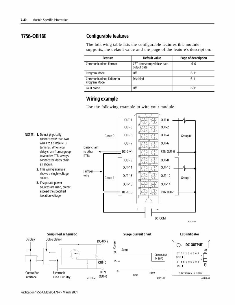
7-40 Module-Specific Information
1756-OB16E Configurable featuresThe following table lists the configurable features this module supports, the default value and the page of the feature’s description:
Wiring exampleUse the following example to wire your module.
Feature Default value Page of description
Communications Format CST timestamped fuse data - output data
6-6
Program Mode Off 6-11
Communications Failure in Program Mode
Disabled 6-11
Fault Mode Off 6-11
OUT-9
OUT-11
OUT-13
OUT-15
DC-1(+)
OUT-1
OUT-3
OUT-5
OUT-7
DC-0(+)
OUT-8
OUT-10
OUT-12
OUT-14
RTN OUT-1
OUT-0
OUT-2
OUT-4
OUT-6
RTN OUT-0
12
34
56
78
910
1112
1314
1516
1718
1920
40174-M
+ –
DC COM
1. Do not physically connect more than two wires to a single RTB terminal. When you daisy chain from a group to another RTB, always connect the daisy chain as shown.
2. This wiring example shows a single voltage source.
3. If separate power sources are used, do not exceed the specified isolation voltage.
NOTES: Group 0
Group 1
Group 0
Group 1
Daisy chain to other RTBs
DC OUTPUT
ST 0 1 2 3 4 5 6 7
ST 8 9 10 1112 13 14 15
OK
FUSE
FUSE
ELECTRONICALLY FUSED
2A
1A
0 10ms
40851-M
ControlBusInterface
ElectronicFuse Circuitry 40464-M
Continuous @ 60oC
Display Optoisolation
RTNOUT-0
OUT-0
DC-0(+)
41113-M
Surge Current Chart
Curre
nt
LED indicatorSimplified schematic
Time
Surge
Jumper wire
Publication 1756-UM058C-EN-P - March 2001
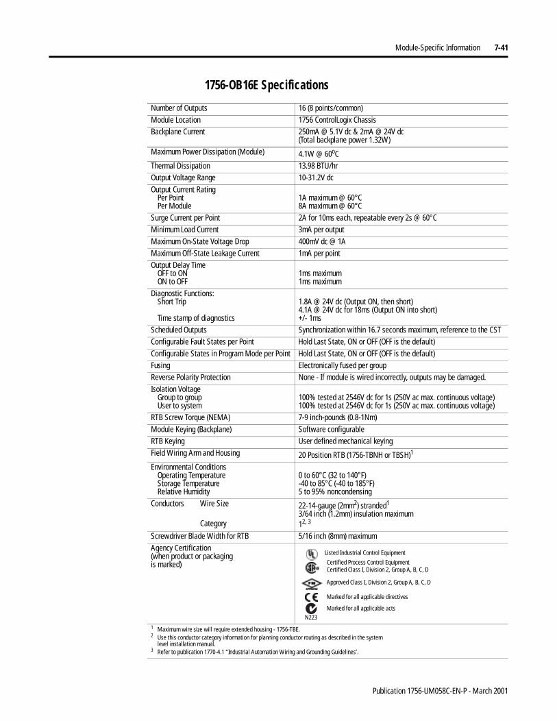
Module-Specific Information 7-41
1756-OB16E Specifications
Number of Outputs 16 (8 points/common)Module Location 1756 ControlLogix ChassisBackplane Current 250mA @ 5.1V dc & 2mA @ 24V dc
(Total backplane power 1.32W)Maximum Power Dissipation (Module) 4.1W @ 60oCThermal Dissipation 13.98 BTU/hrOutput Voltage Range 10-31.2V dcOutput Current Rating
Per PointPer Module
1A maximum @ 60°C8A maximum @ 60°C
Surge Current per Point 2A for 10ms each, repeatable every 2s @ 60°CMinimum Load Current 3mA per outputMaximum On-State Voltage Drop 400mV dc @ 1AMaximum Off-State Leakage Current 1mA per pointOutput Delay Time
OFF to ONON to OFF
1ms maximum1ms maximum
Diagnostic Functions:Short Trip
Time stamp of diagnostics
1.8A @ 24V dc (Output ON, then short)4.1A @ 24V dc for 18ms (Output ON into short)+/- 1ms
Scheduled Outputs Synchronization within 16.7 seconds maximum, reference to the CSTConfigurable Fault States per Point Hold Last State, ON or OFF (OFF is the default)Configurable States in Program Mode per Point Hold Last State, ON or OFF (OFF is the default)Fusing Electronically fused per groupReverse Polarity Protection None - If module is wired incorrectly, outputs may be damaged.Isolation Voltage
Group to groupUser to system
100% tested at 2546V dc for 1s (250V ac max. continuous voltage)100% tested at 2546V dc for 1s (250V ac max. continuous voltage)
RTB Screw Torque (NEMA) 7-9 inch-pounds (0.8-1Nm) Module Keying (Backplane) Software configurableRTB Keying User defined mechanical keyingField Wiring Arm and Housing 20 Position RTB (1756-TBNH or TBSH)1
Environmental ConditionsOperating TemperatureStorage TemperatureRelative Humidity
0 to 60°C (32 to 140°F)-40 to 85°C (-40 to 185°F)5 to 95% noncondensing
Conductors Wire Size
Category
22-14-gauge (2mm2) stranded1
3/64 inch (1.2mm) insulation maximum12, 3
Screwdriver Blade Width for RTB 5/16 inch (8mm) maximumAgency Certification(when product or packagingis marked)
1 Maximum wire size will require extended housing - 1756-TBE.2 Use this conductor category information for planning conductor routing as described in the system
level installation manual.3 Refer to publication 1770-4.1 “Industrial Automation Wiring and Grounding Guidelines’.
Marked for all applicable directives
Approved Class I, Division 2, Group A, B, C, D
Certified Process Control EquipmentCertified Class I, Division 2, Group A, B, C, D
Marked for all applicable actsN223
Listed Industrial Control Equipment
Publication 1756-UM058C-EN-P - March 2001
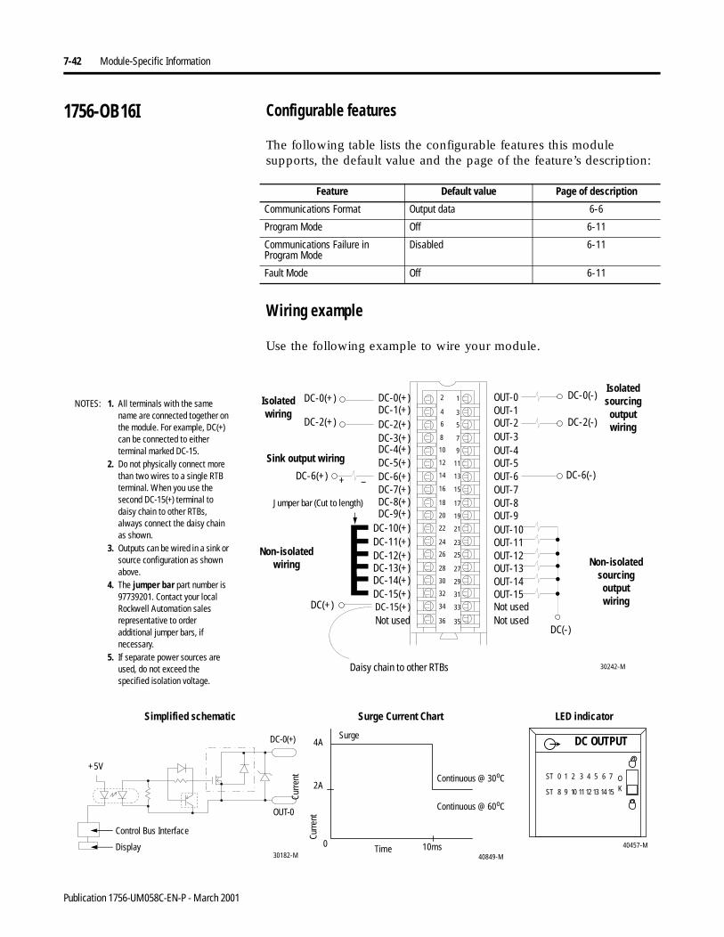
7-42 Module-Specific Information
1756-OB16I Configurable features
The following table lists the configurable features this module supports, the default value and the page of the feature’s description:
Wiring example
Use the following example to wire your module.
Feature Default value Page of description
Communications Format Output data 6-6
Program Mode Off 6-11
Communications Failure in Program Mode
Disabled 6-11
Fault Mode Off 6-11
12
34
56
78
910
1112
1314
1516
1718
1920
2122
2324
2526
2728
2930
3132
3334
3536
DC-0(+)
DC-11(+)
DC-1(+)
DC-10(+)
DC-2(+)
DC-9(+)
DC-6(+)
DC-3(+)
DC-7(+)
DC-4(+)
DC-8(+)
DC-5(+)
DC-15(+)DC-14(+)
DC-15(+)
DC-12(+)DC-13(+)
OUT-0
OUT-8
OUT-5
OUT-7
OUT-9OUT-10OUT-11OUT-12OUT-13OUT-14OUT-15
OUT-4
OUT-6
Non-isolated wiring
Isolatedwiring
DC(+)
DC(-)
DC-6(-)
DC-2(-)
Not used
OUT-1OUT-2OUT-3
DC-2(+)
30242-M
DC-0(-)DC-0(+)
DC-6(+)
Not usedNot used
+ –
1. All terminals with the same name are connected together on the module. For example, DC(+) can be connected to either terminal marked DC-15.
2. Do not physically connect more than two wires to a single RTB terminal. When you use the second DC-15(+) terminal to daisy chain to other RTBs, always connect the daisy chain as shown.
3. Outputs can be wired in a sink or source configuration as shown above.
4. The jumper bar part number is 97739201. Contact your local Rockwell Automation sales representative to order additional jumper bars, if necessary.
5. If separate power sources are used, do not exceed the specified isolation voltage.
NOTES:
Daisy chain to other RTBs
Jumper bar (Cut to length)
Sink output wiring
Non-isolated sourcingoutputwiring
Isolated sourcingoutputwiring
40457-M
DC OUTPUT
ST 0 1 2 3 4 5 6 7
ST 8 9 10 1112 13 14 15
OK
4A
2A
0 10ms
Curr
ent
40849-M30182-M
Control Bus Interface
+5V
Continuous @ 60oC
Display
Surge Current Chart
Curre
nt
LED indicatorSimplified schematic
Time
Surge
Continuous @ 30oC
OUT-0
DC-0(+)
Publication 1756-UM058C-EN-P - March 2001
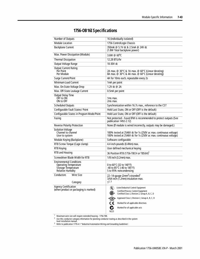
Module-Specific Information 7-43
1756-OB16I Specifications
Number of Outputs 16 (individually isolated)Module Location 1756 ControlLogix ChassisBackplane Current 350mA @ 5.1V dc & 2.5mA @ 24V dc
(1.8W Total backplane power)Max. Power Dissipation (Module) 3.6W @ 60oCThermal Dissipation 12.28 BTU/hrOutput Voltage Range 10-30V dcOutput Current Rating
Per PointPer Module
2A max. @ 30°C & 1A max. @ 60°C (Linear derating)8A max. @ 30°C & 4A max. @ 60°C (Linear derating)
Surge Current/Point 4A for 10ms each, repeatable every 2sMinimum Load Current 1mA per pointMax. On-State Voltage Drop 1.2V dc @ 2AMax. Off-State Leakage Current 0.5mA per pointOutput Delay Time
OFF to ONON to OFF
1ms max.2ms max.
Scheduled Outputs Synchronization within 16.7s max., reference to the CSTConfigurable Fault States/ Point Hold Last State, ON or OFF (OFF is the default)Configurable States in Program Mode/Point Hold Last State, ON or OFF (OFF is the default)Fusing Not protected - Fused IFM is recommended to protect outputs (See
publication 1492-2.12)Reverse Polarity Protection None (If module is wired incorrectly, outputs may be damaged.)Isolation Voltage
Channel to channelUser to system
100% tested at 2546V dc for 1s (250V ac max. continuous voltage)100% tested at 2546V dc for 1s (250V ac max. continuous voltage)
Module Keying (Backplane) Software configurableRTB Screw Torque (Cage clamp) 4.4 inch-pounds (0.4Nm) max.RTB Keying User defined mechanical keyingRTB and Housing 36 Position RTB (1756-TBCH or TBS6H)1
Screwdriver Blade Width for RTB 1/8 inch (3.2mm) max.Environmental Conditions
Operating TemperatureStorage TemperatureRelative Humidity
0 to 60°C (32 to 140°F)-40 to 85°C (-40 to 185°F)5 to 95% noncondensing
Conductors Wire Size
Category
22–14-gauge (2mm2) stranded1
3/64 inch (1.2mm) insulation max.12, 3
Agency Certification(when product or packaging is marked)
1 Maximum wire size will require extended housing - 1756-TBE.2 Use this conductor category information for planning conductor routing as described in the system
level installation manual.3 Refer to publication 1770-4.1 “Industrial Automation Wiring and Grounding Guidelines’.
Marked for all applicable directives
Approved Class I, Division 2, Group A, B, C, D
Certified Process Control EquipmentCertified Class I, Division 2, Group A, B, C, D
Marked for all applicable acts
N223
Listed Industrial Control Equipment
Publication 1756-UM058C-EN-P - March 2001
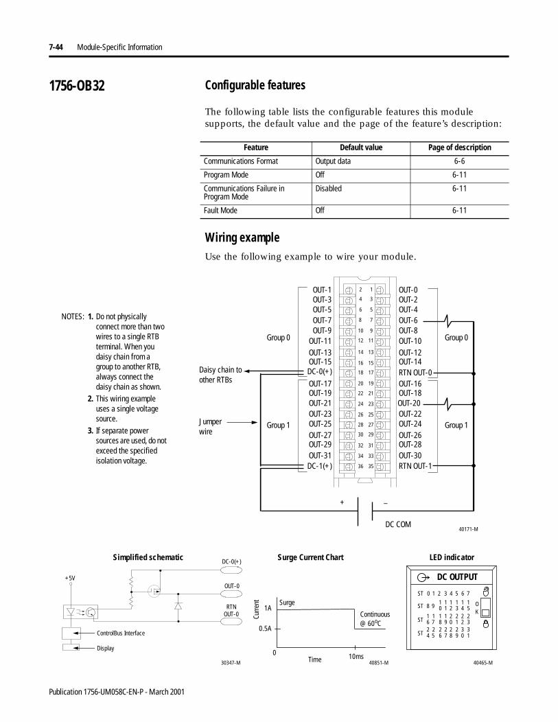
7-44 Module-Specific Information
1756-OB32 Configurable features
The following table lists the configurable features this module supports, the default value and the page of the feature’s description:
Wiring exampleUse the following example to wire your module.
Feature Default value Page of description
Communications Format Output data 6-6
Program Mode Off 6-11
Communications Failure in Program Mode
Disabled 6-11
Fault Mode Off 6-11
OUT-0
OUT-16
OUT-10
OUT-14
OUT-18OUT-20OUT-22OUT-24OUT-26OUT-28OUT-30
OUT-8
OUT-12
OUT-2OUT-4OUT-6
RTN OUT-0
RTN OUT-1
40171-M
12
34
56
78
910
1112
1314
1516
1718
1920
2122
2324
2526
2728
2930
3132
3334
3536
OUT-1
DC-0(+)
OUT-11
OUT-15
OUT-17OUT-19OUT-21OUT-23OUT-25OUT-27OUT-29
OUT-9
OUT-13
OUT-3OUT-5OUT-7
OUT-31DC-1(+)
+ _
DC COM
1. Do not physically connect more than two wires to a single RTB terminal. When you daisy chain from a group to another RTB, always connect the daisy chain as shown.
2. This wiring example uses a single voltage source.
3. If separate power sources are used, do not exceed the specified isolation voltage.
NOTES:
Group 0
Group 1
Group 0
Group 1
Daisy chain to other RTBs
DC OUTPUT
OK
ST 0 1 2 3 4 5 6 7
ST 8 910 21 3 4 5
1 1 1 11
ST 6 718 09 1 2 3
1 2 2 221 1
ST 4 526 87 9 0 1
2 2 2 332 2
40465-M
1A
0.5A
0 10ms40851-M30347-M
Continuous @ 60oC
+5V
RTNOUT-0
OUT-0
DC-0(+)
ControlBus Interface
Display
Surge Current Chart
Curre
nt
LED indicatorSimplified schematic
Time
Surge
Jumper wire
Publication 1756-UM058C-EN-P - March 2001
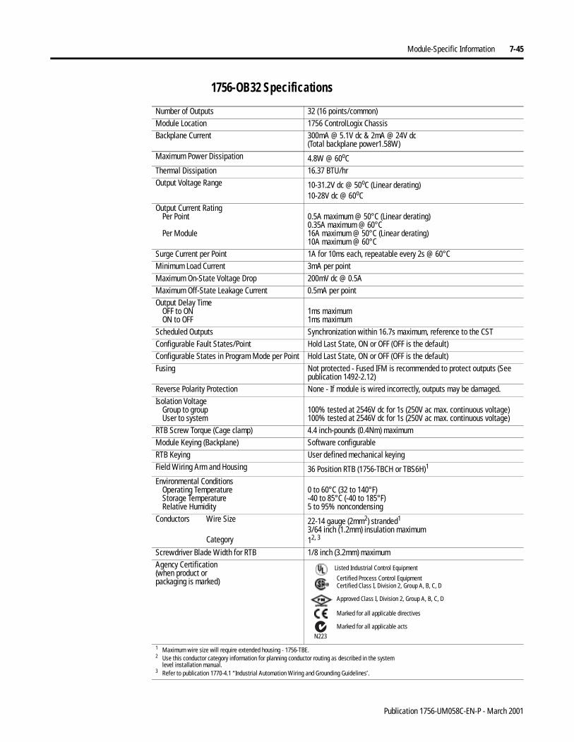
Module-Specific Information 7-45
1756-OB32 Specifications
Number of Outputs 32 (16 points/common)Module Location 1756 ControlLogix ChassisBackplane Current 300mA @ 5.1V dc & 2mA @ 24V dc
(Total backplane power1.58W)Maximum Power Dissipation 4.8W @ 60oCThermal Dissipation 16.37 BTU/hrOutput Voltage Range 10-31.2V dc @ 50oC (Linear derating)
10-28V dc @ 60oCOutput Current Rating
Per Point
Per Module
0.5A maximum @ 50°C (Linear derating)0.35A maximum @ 60°C16A maximum @ 50°C (Linear derating)10A maximum @ 60°C
Surge Current per Point 1A for 10ms each, repeatable every 2s @ 60°CMinimum Load Current 3mA per pointMaximum On-State Voltage Drop 200mV dc @ 0.5AMaximum Off-State Leakage Current 0.5mA per pointOutput Delay Time
OFF to ONON to OFF
1ms maximum1ms maximum
Scheduled Outputs Synchronization within 16.7s maximum, reference to the CSTConfigurable Fault States/Point Hold Last State, ON or OFF (OFF is the default)Configurable States in Program Mode per Point Hold Last State, ON or OFF (OFF is the default)Fusing Not protected - Fused IFM is recommended to protect outputs (See
publication 1492-2.12)Reverse Polarity Protection None - If module is wired incorrectly, outputs may be damaged.Isolation Voltage
Group to groupUser to system
100% tested at 2546V dc for 1s (250V ac max. continuous voltage)100% tested at 2546V dc for 1s (250V ac max. continuous voltage)
RTB Screw Torque (Cage clamp) 4.4 inch-pounds (0.4Nm) maximumModule Keying (Backplane) Software configurableRTB Keying User defined mechanical keyingField Wiring Arm and Housing 36 Position RTB (1756-TBCH or TBS6H)1
Environmental ConditionsOperating TemperatureStorage TemperatureRelative Humidity
0 to 60°C (32 to 140°F)-40 to 85°C (-40 to 185°F)5 to 95% noncondensing
Conductors Wire Size
Category
22-14 gauge (2mm2) stranded1
3/64 inch (1.2mm) insulation maximum12, 3
Screwdriver Blade Width for RTB 1/8 inch (3.2mm) maximumAgency Certification(when product or packaging is marked)
1 Maximum wire size will require extended housing - 1756-TBE.2 Use this conductor category information for planning conductor routing as described in the system
level installation manual.3 Refer to publication 1770-4.1 “Industrial Automation Wiring and Grounding Guidelines’.
Marked for all applicable directives
Approved Class I, Division 2, Group A, B, C, D
Certified Process Control EquipmentCertified Class I, Division 2, Group A, B, C, D
Marked for all applicable actsN223
Listed Industrial Control Equipment
Publication 1756-UM058C-EN-P - March 2001
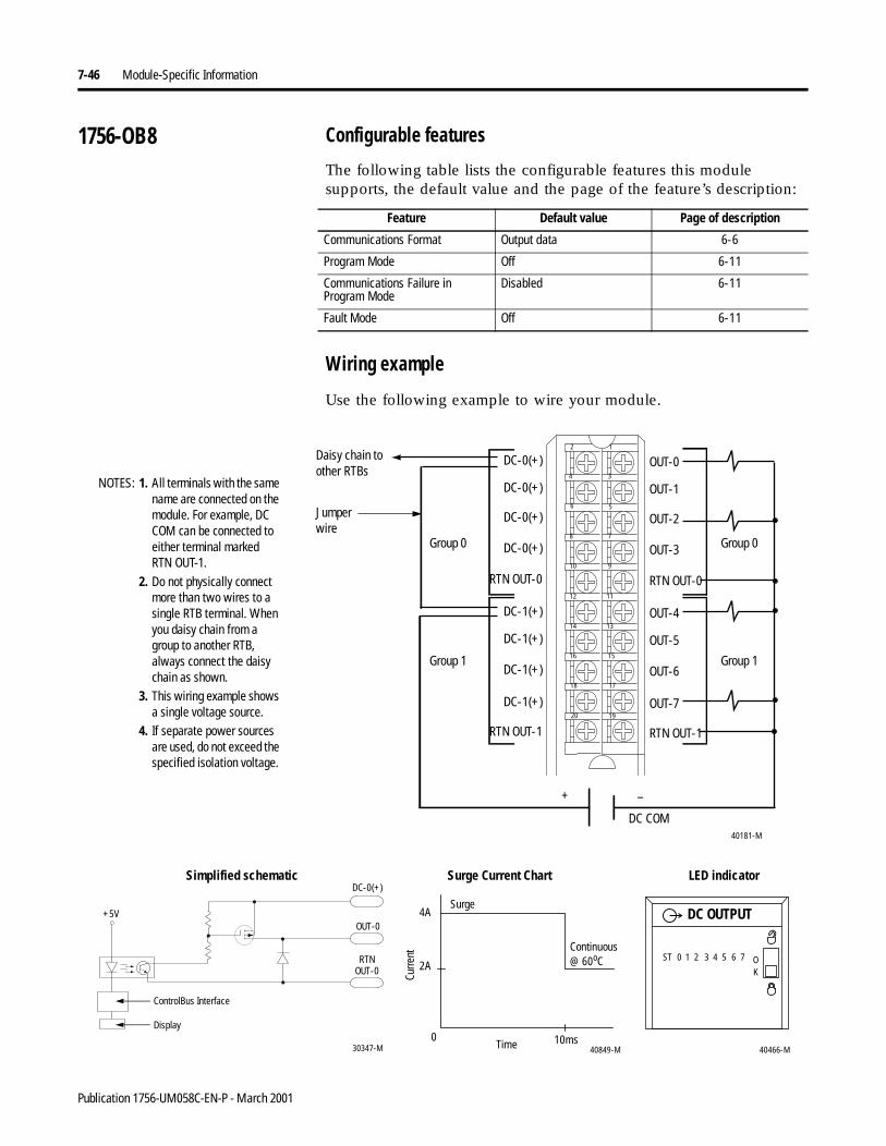
7-46 Module-Specific Information
1756-OB8 Configurable features
The following table lists the configurable features this module supports, the default value and the page of the feature’s description:
Wiring example
Use the following example to wire your module.
Feature Default value Page of description
Communications Format Output data 6-6
Program Mode Off 6-11
Communications Failure in Program Mode
Disabled 6-11
Fault Mode Off 6-11
40181-M
1. All terminals with the same name are connected on the module. For example, DC COM can be connected to either terminal markedRTN OUT-1.
2. Do not physically connect more than two wires to a single RTB terminal. When you daisy chain from a group to another RTB, always connect the daisy chain as shown.
3. This wiring example shows a single voltage source.
4. If separate power sources are used, do not exceed the specified isolation voltage.
DC-1(+)
DC-1(+)
DC-1(+)
DC-1(+)
RTN OUT-1
DC-0(+)
DC-0(+)
DC-0(+)
DC-0(+)
RTN OUT-0
OUT-4
OUT-5
OUT-6
OUT-7
RTN OUT-1
OUT-0
OUT-1
OUT-2
OUT-3
RTN OUT-0
12
34
56
78
910
1112
1314
1516
1718
1920
+ –
DC COM
NOTES:
Group 0
Group 1
Group 0
Group 1
Daisy chain to other RTBs
30347-M
+5V
RTNOUT-0
OUT-0
DC-0(+)
ControlBus Interface
Display
40466-M
DC OUTPUT
ST 0 1 2 3 4 5 6 7 OK
4A
2A
0 10ms40849-M
Continuous @ 60oC
Surge Current Chart
Curre
nt
LED indicatorSimplified schematic
Time
Surge
Jumper wire
Publication 1756-UM058C-EN-P - March 2001

Module-Specific Information 7-47
1756-OB8 Specifications
Number of Outputs 8 (4 points/common)Module Location 1756 ControlLogix ChassisBackplane Current 165mA @ 5.1V dc & 2mA @ 24V dc
(Total backplane power 0.89W)Maximum Power Dissipation (Module) 2.5W @ 60oCThermal Dissipation 8.53 BTU/hrOutput Voltage Range 10-30V dcOutput Current Rating
Per PointPer Module
2A maximum @ 60°C8A maximum @ 60°C
Surge Current per Point 4A for 10ms each, repeatable every 1s @ 60°CMinimum Load Current 2mA per pointMaximum On-State Voltage Drop 2V dc @ 2AMaximum Off-State Leakage Current 1mA per pointOutput Delay Time
OFF to ONON to OFF
1ms maximum2ms maximum
Scheduled Outputs Synchronization within 16.7s maximum, reference to the CSTConfigurable Fault States/Point Hold Last State, ON or OFF (OFF is the default)Configurable States in Program Mode/Point Hold Last State, ON or OFF (OFF is the default)Fusing Not protected - Fused IFM is recommended to protect outputs (See
publication 1492-2.12)Reverse Polarity Protection None - If module is wired incorrectly, outputs may be damaged.Isolation Voltage
Group to groupUser to system
100% tested at 2546V dc for 1s (250V ac max. continuous voltage)100% tested at 2546V dc for 1s (250V ac max. continuous voltage)
Module Keying (Backplane) Software configurableRTB Screw Torque (NEMA) 7-9 inch-pounds (0.8-1Nm) RTB Keying User defined mechanical keyingRTB and Housing 20 Position RTB (1756-TBNH or TBSH)1
Environmental ConditionsOperating TemperatureStorage TemperatureRelative Humidity
0 to 60°C (32 to 140°F)-40 to 85°C (-40 to 185°F)5 to 95% noncondensing
Conductors Wire Size
Category
22-14-gauge (2mm2) stranded1
3/64 inch (1.2mm) insulation maximum12, 3
Screwdriver Blade Width for RTB 5/16 inch (8mm) maximumAgency Certification(when product orpackaging is marked)
1 Maximum wire size will require extended housing - 1756-TBE.2 Use this conductor category information for planning conductor routing as described in the system
level installation manual.3 Refer to publication 1770-4.1 “Industrial Automation Wiring and Grounding Guidelines’.
Marked for all applicable directives
Approved Class I, Division 2, Group A, B, C, D
Certified Process Control EquipmentCertified Class I, Division 2, Group A, B, C, D
Marked for all applicable acts
N223
Listed Industrial Control Equipment
Publication 1756-UM058C-EN-P - March 2001
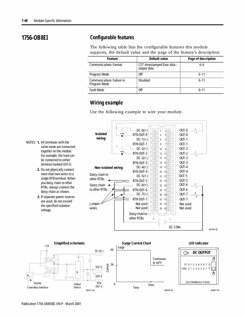
7-48 Module-Specific Information
1756-OB8EI Configurable features
The following table lists the configurable features this module supports, the default value and the page of the feature’s description:
Wiring example
Use the following example to wire your module.
Feature Default value Page of description
Communications Format CST timestamped fuse data - output data
6-6
Program Mode Off 6-11
Communications Failure in Program Mode
Disabled 6-11
Fault Mode Off 6-11
Non-isolated wiring
Isolatedwiring
12
34
56
78
910
1112
1314
1516
1718
1920
2122
2324
2526
2728
2930
3132
3334
3536
DC-0(+)
RTN OUT-5
RTN OUT-0
DC-5(+)
DC-1(+)
RTN OUT-4
DC-3(+)
RTN OUT-1
RTN OUT-3
DC-2(+)
DC-4(+)
RTN OUT-2
RTN OUT-7DC-7(+)
Not used
DC-6(+)RTN OUT-6
OUT-0
OUT-4
OUT-2
OUT-3
OUT-4OUT-5OUT-5OUT-6OUT-6OUT-7OUT-7
OUT-2
OUT-3
OUT-0OUT-1OUT-1
Not usedNot usedNot used
40169-M
+
+
-
-
+ –
DC COM
1. All terminals with the same name are connected together on the module. For example, the load can be connected to either terminal marked OUT-0.
2. Do not physically connect more than two wires to a single RTB terminal. When you daisy chain to other RTBs, always connect the daisy chain as shown.
3. If separate power sources are used, do not exceed the specified isolation voltage.
NOTES:
Daisy chain to other RTBs
Daisy chain to other RTBs
40467-M
DC OUTPUT
ST 0 1 2 3 4 5 6 7 OKFUSE
ELECTRONICALLY FUSED
0 1 2 3 4 5 6 7
4A
2A
0 10ms
40849-M30351-M
Continuous @ 60oC
ControlBus Interface
Display
+5V
OutputDevice
OUT-0
RTNOUT-0
DC-0(+)
OUT-0
Surge Current Chart
Curre
nt
LED indicatorSimplified schematic
Time
Surge
Daisy chain to other RTBs
Jumper wires
Publication 1756-UM058C-EN-P - March 2001
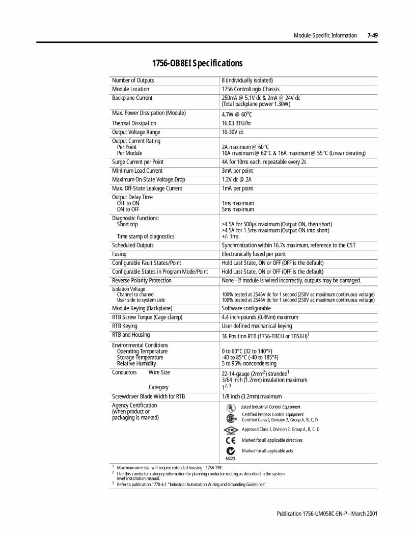
Module-Specific Information 7-49
1756-OB8EI Specifications
Number of Outputs 8 (individually isolated)Module Location 1756 ControlLogix ChassisBackplane Current 250mA @ 5.1V dc & 2mA @ 24V dc
(Total backplane power 1.30W)Max. Power Dissipation (Module) 4.7W @ 60oCThermal Dissipation 16.03 BTU/hrOutput Voltage Range 10-30V dcOutput Current Rating
Per PointPer Module
2A maximum @ 60°C10A maximum @ 60°C & 16A maximum @ 55°C (Linear derating)
Surge Current per Point 4A for 10ms each, repeatable every 2sMinimum Load Current 3mA per pointMaximum On-State Voltage Drop 1.2V dc @ 2AMax. Off-State Leakage Current 1mA per pointOutput Delay Time
OFF to ONON to OFF
1ms maximum5ms maximum
Diagnostic Functions:Short trip
Time stamp of diagnostics
>4.5A for 500µs maximum (Output ON, then short)>4.5A for 1.5ms maximum (Output ON into short)+/- 1ms
Scheduled Outputs Synchronization within 16.7s maximum, reference to the CSTFusing Electronically fused per pointConfigurable Fault States/Point Hold Last State, ON or OFF (OFF is the default)Configurable States in Program Mode/Point Hold Last State, ON or OFF (OFF is the default)Reverse Polarity Protection None - If module is wired incorrectly, outputs may be damaged.Isolation Voltage
Channel to channelUser side to system side
100% tested at 2546V dc for 1 second (250V ac maximum continuous voltage)100% tested at 2546V dc for 1 second (250V ac maximum continuous voltage)
Module Keying (Backplane) Software configurableRTB Screw Torque (Cage clamp) 4.4 inch-pounds (0.4Nm) maximumRTB Keying User defined mechanical keyingRTB and Housing 36 Position RTB (1756-TBCH or TBS6H)1
Environmental ConditionsOperating TemperatureStorage TemperatureRelative Humidity
0 to 60°C (32 to 140°F)-40 to 85°C (-40 to 185°F)5 to 95% noncondensing
Conductors Wire Size
Category
22-14-gauge (2mm2) stranded1
3/64 inch (1.2mm) insulation maximum12, 3
Screwdriver Blade Width for RTB 1/8 inch (3.2mm) maximumAgency Certification(when product orpackaging is marked)
1 Maximum wire size will require extended housing - 1756-TBE.2 Use this conductor category information for planning conductor routing as described in the system
level installation manual.3 Refer to publication 1770-4.1 “Industrial Automation Wiring and Grounding Guidelines’.
Marked for all applicable directives
Approved Class I, Division 2, Group A, B, C, D
Certified Process Control EquipmentCertified Class I, Division 2, Group A, B, C, D
Marked for all applicable acts
N223
Listed Industrial Control Equipment
Publication 1756-UM058C-EN-P - March 2001
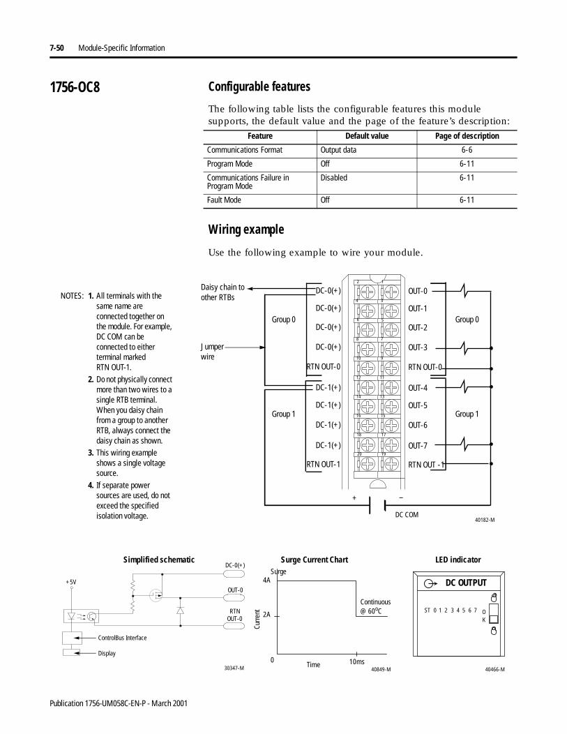
7-50 Module-Specific Information
1756-OC8 Configurable features
The following table lists the configurable features this module supports, the default value and the page of the feature’s description:
Wiring example
Use the following example to wire your module.
Feature Default value Page of description
Communications Format Output data 6-6
Program Mode Off 6-11
Communications Failure in Program Mode
Disabled 6-11
Fault Mode Off 6-11
40182-M
1. All terminals with the same name are connected together on the module. For example, DC COM can be connected to either terminal markedRTN OUT-1.
2. Do not physically connect more than two wires to a single RTB terminal. When you daisy chain from a group to another RTB, always connect the daisy chain as shown.
3. This wiring example shows a single voltage source.
4. If separate power sources are used, do not exceed the specified isolation voltage.
DC-1(+)
DC-1(+)
DC-1(+)
DC-1(+)
RTN OUT-1
DC-0(+)
DC-0(+)
DC-0(+)
DC-0(+)
RTN OUT-0
OUT-4
OUT-5
OUT-6
OUT-7
RTN OUT -1
OUT-0
OUT-1
OUT-2
OUT-3
RTN OUT-0
12
34
56
78
910
1112
1314
1516
1718
1920
+ –
DC COM
NOTES:
Group 0
Group 1
Group 0
Group 1
Daisy chain to other RTBs
40466-M
DC OUTPUT
ST 0 1 2 3 4 5 6 7 OK
4A
2A
0 10ms40849-M
Continuous @ 60oC
30347-M
+5V
RTNOUT-0
OUT-0
DC-0(+)
ControlBus Interface
Display
Surge Current Chart
Curre
nt
LED indicatorSimplified schematic
Time
Surge
Jumper wire
Publication 1756-UM058C-EN-P - March 2001
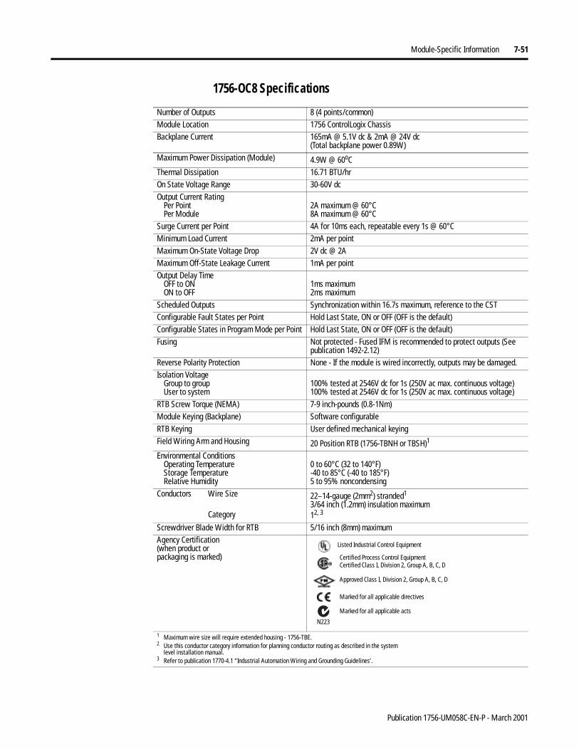
Module-Specific Information 7-51
1756-OC8 Specifications
Number of Outputs 8 (4 points/common)Module Location 1756 ControlLogix ChassisBackplane Current 165mA @ 5.1V dc & 2mA @ 24V dc
(Total backplane power 0.89W)Maximum Power Dissipation (Module) 4.9W @ 60oCThermal Dissipation 16.71 BTU/hrOn State Voltage Range 30-60V dcOutput Current Rating
Per PointPer Module
2A maximum @ 60°C8A maximum @ 60°C
Surge Current per Point 4A for 10ms each, repeatable every 1s @ 60°CMinimum Load Current 2mA per pointMaximum On-State Voltage Drop 2V dc @ 2AMaximum Off-State Leakage Current 1mA per pointOutput Delay Time
OFF to ONON to OFF
1ms maximum2ms maximum
Scheduled Outputs Synchronization within 16.7s maximum, reference to the CSTConfigurable Fault States per Point Hold Last State, ON or OFF (OFF is the default)Configurable States in Program Mode per Point Hold Last State, ON or OFF (OFF is the default)Fusing Not protected - Fused IFM is recommended to protect outputs (See
publication 1492-2.12)Reverse Polarity Protection None - If the module is wired incorrectly, outputs may be damaged.Isolation Voltage
Group to groupUser to system
100% tested at 2546V dc for 1s (250V ac max. continuous voltage)100% tested at 2546V dc for 1s (250V ac max. continuous voltage)
RTB Screw Torque (NEMA) 7-9 inch-pounds (0.8-1Nm) Module Keying (Backplane) Software configurableRTB Keying User defined mechanical keyingField Wiring Arm and Housing 20 Position RTB (1756-TBNH or TBSH)1
Environmental ConditionsOperating TemperatureStorage TemperatureRelative Humidity
0 to 60°C (32 to 140°F)-40 to 85°C (-40 to 185°F)5 to 95% noncondensing
Conductors Wire Size
Category
22–14-gauge (2mm2) stranded1
3/64 inch (1.2mm) insulation maximum12, 3
Screwdriver Blade Width for RTB 5/16 inch (8mm) maximumAgency Certification(when product orpackaging is marked)
1 Maximum wire size will require extended housing - 1756-TBE.2 Use this conductor category information for planning conductor routing as described in the system
level installation manual.3 Refer to publication 1770-4.1 “Industrial Automation Wiring and Grounding Guidelines’.
Marked for all applicable directives
Approved Class I, Division 2, Group A, B, C, D
Certified Process Control EquipmentCertified Class I, Division 2, Group A, B, C, D
Marked for all applicable acts
N223
Listed Industrial Control Equipment
Publication 1756-UM058C-EN-P - March 2001
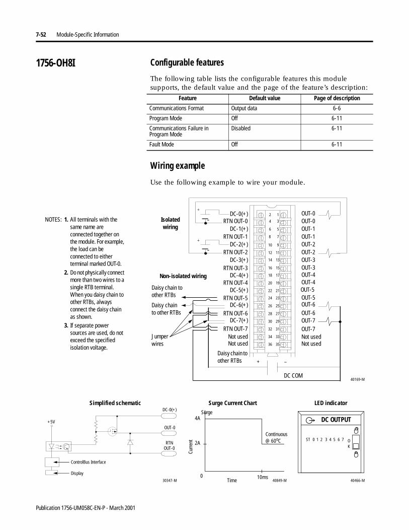
7-52 Module-Specific Information
1756-OH8I Configurable features
The following table lists the configurable features this module supports, the default value and the page of the feature’s description:
Wiring example
Use the following example to wire your module.
Feature Default value Page of description
Communications Format Output data 6-6
Program Mode Off 6-11
Communications Failure in Program Mode
Disabled 6-11
Fault Mode Off 6-11
40466-M
DC OUTPUT
ST 0 1 2 3 4 5 6 7 OK
4A
2A
0 10ms40849-M30347-M
+5V
RTNOUT-0
OUT-0
DC-0(+)
ControlBus Interface
Display
Continuous @ 60oC
Surge Current Chart
Curre
nt
LED indicatorSimplified schematic
Time
Surge
Non-isolated wiring
Isolatedwiring
12
34
56
78
910
1112
1314
1516
1718
1920
2122
2324
2526
2728
2930
3132
3334
3536
DC-0(+)
RTN OUT-5
RTN OUT-0
DC-5(+)
DC-1(+)
RTN OUT-4
DC-3(+)
RTN OUT-1
RTN OUT-3
DC-2(+)
DC-4(+)
RTN OUT-2
RTN OUT-7DC-7(+)
Not used
DC-6(+)RTN OUT-6
OUT-0
OUT-4
OUT-2
OUT-3
OUT-4OUT-5OUT-5OUT-6OUT-6OUT-7OUT-7
OUT-2
OUT-3
OUT-0OUT-1OUT-1
Not usedNot usedNot used
40169-M
+
+
-
-
+ –
DC COM
1. All terminals with the same name are connected together on the module. For example, the load can be connected to either terminal marked OUT-0.
2. Do not physically connect more than two wires to a single RTB terminal. When you daisy chain to other RTBs, always connect the daisy chain as shown.
3. If separate power sources are used, do not exceed the specified isolation voltage.
NOTES:
Daisy chain to other RTBs
Daisy chain to other RTBs
Daisy chain to other RTBs
Jumper wires
Publication 1756-UM058C-EN-P - March 2001

Module-Specific Information 7-53
1756-OH8I Specifications
Number of Outputs 8 (individually isolated)Module Location 1756 ControlLogix ChassisBackplane Current 210mA @ 5.1V dc & 2mA @ 24V dc
(Total backplane power 1.11W)Maximum Power Dissipation (Module) 3.3W @ 60oCThermal Dissipation 11.25 BTU/hrOn State Voltage Range 90-146V dcOutput Current Rating
Per PointPer Module
2A maximum @ 60°C8A maximum @ 60°C
Surge Current per Point 4A for 10ms each, repeatable every 1s @ 60°CMinimum Load Current 2mA per pointMaximum On-State Voltage Drop 2V dc @ 2AMaximum Off-State Leakage Current 1mA per pointOutput Delay Time
OFF to ONON to OFF
2ms maximum2ms maximum
Scheduled Outputs Synchronization within 16.7 seconds maximum, reference to the CSTConfigurable Fault States/Point Hold Last State, ON or OFF (OFF is the default)Configurable States in Program Mode per Point Hold Last State, ON or OFF (OFF is the default)Fusing Not protected - Fused IFM is recommended to protect outputs (See
publication 1492-2.12)Reverse Polarity Protection None - If module is wired incorrectly, outputs may be damaged.Isolation Voltage
Channel to channelUser to system
100% tested at 2546V dc for 1 second (250V ac maximum continuous voltage)100% tested at 2546V dc for 1 second (250V ac maximum continuous voltage)
Module Keying (Backplane) Software configurableRTB Screw Torque (Cage clamp) 4.4 inch-pounds (0.4Nm) maximumRTB Keying User defined mechanical keyingRTB and Housing 36 Position RTB (1756-TBCH or TBS6H)1
Environmental ConditionsOperating TemperatureStorage TemperatureRelative Humidity
0 to 60°C (32 to 140°F)-40 to 85°C (-40 to 185°F)5 to 95% noncondensing
Conductors Wire Size
Category
22-14-gauge (2mm2) stranded1
3/64 inch (1.2mm) insulation maximum12, 3
Screwdriver Blade Width for RTB 1/8 inch (3.2mm) maximumAgency Certification(when product is marked)
1 Maximum wire size will require extended housing - 1756-TBE.2 Use this conductor category information for planning conductor routing as described in the system
level installation manual.3 Refer to publication 1770-4.1 “Industrial Automation Wiring and Grounding Guidelines’.
Marked for all applicable directives
Approved Class I, Division 2, Group A, B, C, D
Certified Process Control EquipmentCertified Class I, Division 2, Group A, B, C, D
Marked for all applicable acts
N223
Listed Industrial Control Equipment
Publication 1756-UM058C-EN-P - March 2001
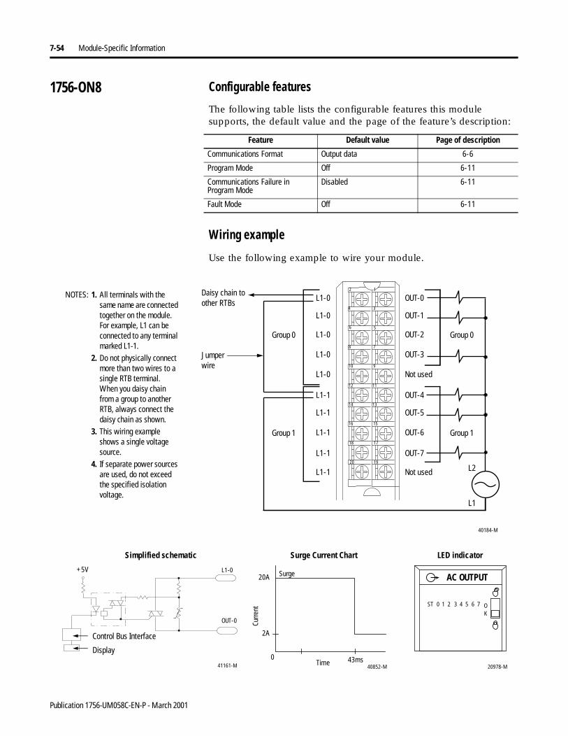
7-54 Module-Specific Information
1756-ON8 Configurable features
The following table lists the configurable features this module supports, the default value and the page of the feature’s description:
Wiring example
Use the following example to wire your module.
Feature Default value Page of description
Communications Format Output data 6-6
Program Mode Off 6-11
Communications Failure in Program Mode
Disabled 6-11
Fault Mode Off 6-11
40184-M
1. All terminals with the same name are connected together on the module. For example, L1 can be connected to any terminal marked L1-1.
2. Do not physically connect more than two wires to a single RTB terminal. When you daisy chain from a group to another RTB, always connect the daisy chain as shown.
3. This wiring example shows a single voltage source.
4. If separate power sources are used, do not exceed the specified isolation voltage.
L1-1
L1-1
L1-1
L1-1
L1-1
L1-0
L1-0
L1-0
L1-0
L1-0
OUT-4
OUT-5
OUT-6
OUT-7
Not used
OUT-0
OUT-1
OUT-2
OUT-3
Not used
12
34
56
78
910
1112
1314
1516
1718
1920
L1
L2
NOTES:
Group 0
Group 1
Group 0
Group 1
Daisy chain to other RTBs
20978-M
ST 0 1 2 3 4 5 6 7 OK
AC OUTPUT20A
2A
0 43ms40852-M
Control Bus Interface
41161-M
+5V
OUT-0
L1-0
Display
Surge Current Chart
Curre
nt
LED indicatorSimplified schematic
Time
Surge
Jumper wire
Publication 1756-UM058C-EN-P - March 2001
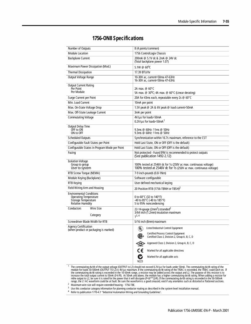
Module-Specific Information 7-55
1756-ON8 Specifications
Number of Outputs 8 (4 points/common)
Module Location 1756 ControlLogix Chassis
Backplane Current 200mA @ 5.1V dc & 2mA @ 24V dc(Total backplane power 1.07)
Maximum Power Dissipation (Mod.) 5.1W @ 60oC
Thermal Dissipation 17.39 BTU/hr
Output Voltage Range 10-30V ac, current>50ma 47-63Hz16-30V ac, current<50ma 47-63Hz
Output Current RatingPer PointPer Module
2A max. @ 60°C5A max. @ 30oC; 4A max. @ 60°C (Linear derating)
Surge Current per Point 20A for 43ms each, repeatable every 2s @ 60°C
Min. Load Current 10mA per point
Max. On-State Voltage Drop 1.5V peak @ 2A & 6V peak @ load current<50mA
Max. Off-State Leakage Current 3mA per point
Commutating Voltage 4V/µs for loads>50mA0.2V/µs for loads<50mA1
Output Delay TimeOFF to ONON to OFF
9.3ms @ 60Hz: 11ms @ 50Hz9.3ms @ 60Hz: 11ms @ 50Hz
Scheduled Outputs Synchronization within 16.7s maximum, reference to the CST
Configurable Fault States per Point Hold Last State, ON or OFF (OFF is the default)
Configurable States in Program Mode per Point Hold Last State, ON or OFF (OFF is the default)
Fusing Not protected - Fused IFM is recommended to protect outputs(See publication 1492-2.12)
Isolation VoltageGroup to groupUser to system
100% tested at 2546V dc for 1s (250V ac max. continuous voltage)100% tested at 2546V dc for 1s (250V ac max. continuous voltage)
RTB Screw Torque (NEMA) 7-9 inch-pounds (0.8-1Nm)
Module Keying (Backplane) Software configurable
RTB Keying User defined mechanical keying
Field Wiring Arm and Housing 20 Position RTB (1756-TBNH or TBSH)2
Environmental ConditionsOperating TemperatureStorage TemperatureRelative Humidity
0 to 60°C (32 to 140°F)-40 to 85°C (-40 to 185°F)5 to 95% noncondensing
Conductors Wire Size
Category
22-14-gauge (2mm2) stranded2
3/64 inch (1.2mm) insulation maximum13, 4
Screwdriver Blade Width for RTB 5/16 inch (8mm) maximum
Agency Certification(when product or packaging is marked)
1 The commutating dv/dt of the output voltage (OUTPUT to L2) should not exceed 0.2V/µs for loads under 50mA. The commutating dv/dt rating of the module for loads 50-500mA (OUTPUT TO L2) is 4V/µs maximum. If the commutating dv/dt rating of the TRIAC is exceeded, the TRIAC could latch on. If the commutating dv/dt rating is exceeded in the 10-50mA range, a resistor may be added across the output and L2. The purpose of this resistor is to increase the total output current to 50mA (I=V/R). At 50mA and above, the module has a higher commutating dv/dt rating. When adding a resistor for mthe output to L2, be sure it is rated for the power that it will dissipate (P=(V**2)/R). If the commutating dv/dt rating is exceeded in the 50-500mA range, the L1 AC waveform could be at fault. Be sure the waveform is a good sinusoid, void if any anomalies such as distorted or flattened sections.
2 Maximum wire size will require extended housing - 1756-TBE.3 Use this conductor category information for planning conductor routing as described in the system level installation manual.4 Refer to publication 1770-4.1 “Industrial Automation Wiring and Grounding Guidelines’.
Marked for all applicable directives
Approved Class I, Division 2, Group A, B, C, D
Certified Process Control EquipmentCertified Class I, Division 2, Group A, B, C, D
Marked for all applicable acts
N223
Listed Industrial Control Equipment
Publication 1756-UM058C-EN-P - March 2001
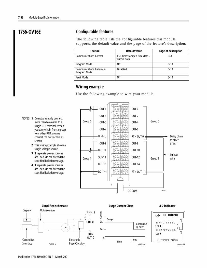
7-56 Module-Specific Information
1756-OV16E Configurable featuresThe following table lists the configurable features this module supports, the default value and the page of the feature’s description:
Wiring exampleUse the following example to wire your module.
Feature Default value Page of description
Communications Format CST timestamped fuse data - output data
6-6
Program Mode Off 6-11
Communications Failure in Program Mode
Disabled 6-11
Fault Mode Off 6-11
NOTES:
Daisy chain to other RTBs
DC OUTPUT
ST 0 1 2 3 4 5 6 7
ST 8 9 10 1112 13 14 15
OK
FUSE
FUSE
ELECTRONICALLY FUSED
2A
1A
0 10ms
40851-M
ControlBusInterface
ElectronicFuse Circuitry 40464-M
Continuous @ 60oC
Display Optoisolation
RTNOUT-0
OUT-0
DC-0(+)
42673-M
Surge Current Chart
Curre
nt
LED indicatorSimplified schematic
Time
Surge
Jumper wire
12
34
56
78
910
1112
1314
1516
1718
1920
+ –
1. Do not physically connect more than two wires to a single RTB terminal. When you daisy chain from a group to another RTB, always connect the daisy chain as shown.
2. This wiring example shows a single voltage source.
3. If separate power sources are used, do not exceed the specified isolation voltage.
4. If separate power sources are used, do not exceed the specified isolation voltage.
Group 0Group 0
Group 1Group 1
DC COM
OUT-1
OUT-3
OUT-5
OUT-7
OUT-9
OUT-11
OUT-13
OUT-15
DC-0(+)
DC-1(+)
OUT-0
OUT-2
OUT-4
OUT-6
OUT-8
OUT-10
OUT-12
OUT-14
RTN OUT-0
RTN OUT-1
42551
Publication 1756-UM058C-EN-P - March 2001
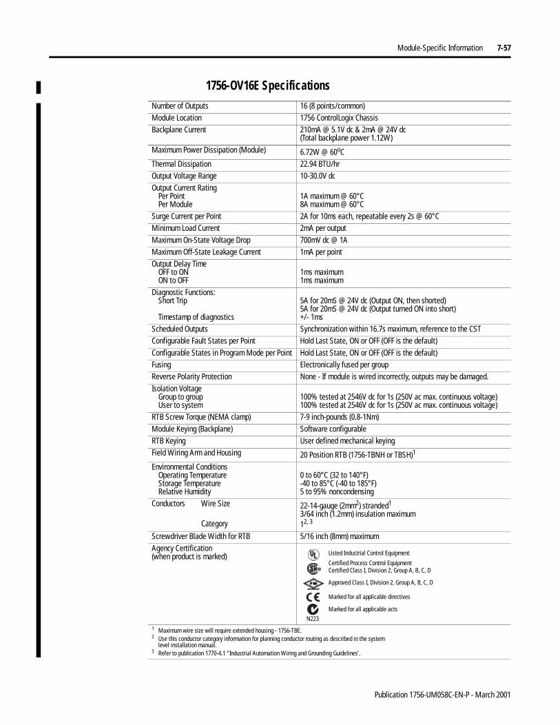
Module-Specific Information 7-57
1756-OV16E Specifications Number of Outputs 16 (8 points/common)Module Location 1756 ControlLogix ChassisBackplane Current 210mA @ 5.1V dc & 2mA @ 24V dc
(Total backplane power 1.12W)Maximum Power Dissipation (Module) 6.72W @ 60oCThermal Dissipation 22.94 BTU/hrOutput Voltage Range 10-30.0V dcOutput Current Rating
Per PointPer Module
1A maximum @ 60°C8A maximum @ 60°C
Surge Current per Point 2A for 10ms each, repeatable every 2s @ 60°CMinimum Load Current 2mA per outputMaximum On-State Voltage Drop 700mV dc @ 1AMaximum Off-State Leakage Current 1mA per pointOutput Delay Time
OFF to ONON to OFF
1ms maximum1ms maximum
Diagnostic Functions:Short Trip
Timestamp of diagnostics
5A for 20mS @ 24V dc (Output ON, then shorted)5A for 20mS @ 24V dc (Output turned ON into short)+/- 1ms
Scheduled Outputs Synchronization within 16.7s maximum, reference to the CSTConfigurable Fault States per Point Hold Last State, ON or OFF (OFF is the default)Configurable States in Program Mode per Point Hold Last State, ON or OFF (OFF is the default)Fusing Electronically fused per groupReverse Polarity Protection None - If module is wired incorrectly, outputs may be damaged.Isolation Voltage
Group to groupUser to system
100% tested at 2546V dc for 1s (250V ac max. continuous voltage)100% tested at 2546V dc for 1s (250V ac max. continuous voltage)
RTB Screw Torque (NEMA clamp) 7-9 inch-pounds (0.8-1Nm) Module Keying (Backplane) Software configurableRTB Keying User defined mechanical keyingField Wiring Arm and Housing 20 Position RTB (1756-TBNH or TBSH)1
Environmental ConditionsOperating TemperatureStorage TemperatureRelative Humidity
0 to 60°C (32 to 140°F)-40 to 85°C (-40 to 185°F)5 to 95% noncondensing
Conductors Wire Size
Category
22-14-gauge (2mm2) stranded1
3/64 inch (1.2mm) insulation maximum12, 3
Screwdriver Blade Width for RTB 5/16 inch (8mm) maximumAgency Certification(when product is marked)
1 Maximum wire size will require extended housing - 1756-TBE.2 Use this conductor category information for planning conductor routing as described in the system
level installation manual.3 Refer to publication 1770-4.1 “Industrial Automation Wiring and Grounding Guidelines’.
Marked for all applicable directives
Approved Class I, Division 2, Group A, B, C, D
Certified Process Control EquipmentCertified Class I, Division 2, Group A, B, C, D
Marked for all applicable actsN223
Listed Industrial Control Equipment
Publication 1756-UM058C-EN-P - March 2001
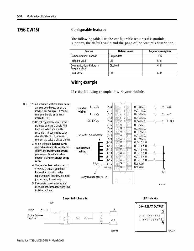
7-58 Module-Specific Information
1756-OW16I Configurable features
The following table lists the configurable features this module supports, the default value and the page of the feature’s description:
Wiring example
Use the following example to wire your module.
Feature Default value Page of description
Communications Format Output data 6-6
Program Mode Off 6-11
Communications Failure in Program Mode
Disabled 6-11
Fault Mode Off 6-11
L1-0
L1-11
L1-1
L1-10
L1-2
L1-9
L1-6
L1-3
L1-7
L1-4
L1-8
L1-5
L1-15L1-14
L1-15
L1-12L1-13
30240-M
Not used
OUT-0 N.O.
OUT-4 N.O.OUT-5 N.O.OUT-6 N.O.OUT-7 N.O.OUT-8 N.O.OUT-9 N.O.OUT-10 N.O.OUT-11 N.O.OUT-12 N.O.OUT-13 N.O.OUT-14 N.O.OUT-15 N.O.
OUT-1 N.O.OUT-2 N.O.OUT-3 N.O.
Not usedNot used
Non-isolated wiring
Isolatedwiring
L1-0
L1-2
DC-4(+)
L1
L2
L2-0
L2-2
DC-4(-)
12
34
56
78
910
1112
1314
1516
1718
1920
2122
2324
2526
2728
2930
3132
3334
3536
1. All terminals with the same name are connected together on the module. For example, L1 can be connected to either terminal marked L1-15.
2. Do not physically connect more than two wires to a single RTB terminal. When you use the second L1-15 terminal to daisy chain to other RTBs, always connect the daisy chain as shown.
3. When using the jumper bar to daisy chain terminals together as shown, the maximum current you may apply to the module through a single contact point is 8A.
4. The jumper bar part number is 97739201. Contact your local Rockwell Automation sales representative to order additional jumper bars, if necessary.
5. If separate power sources are used, do not exceed the specified isolation voltage.
NOTES:
Daisy chain to other RTBs
Jumper bar (Cut to length)
40455-M
ST 0 1 2 3 4 5 6 7
ST 8 9 10 11 12 13 14 15
OK
RELAY OUTPUT
30337-M
Control Bus Interface
Display
OUT
L1
+24V
LED indicatorSimplified schematic
Publication 1756-UM058C-EN-P - March 2001
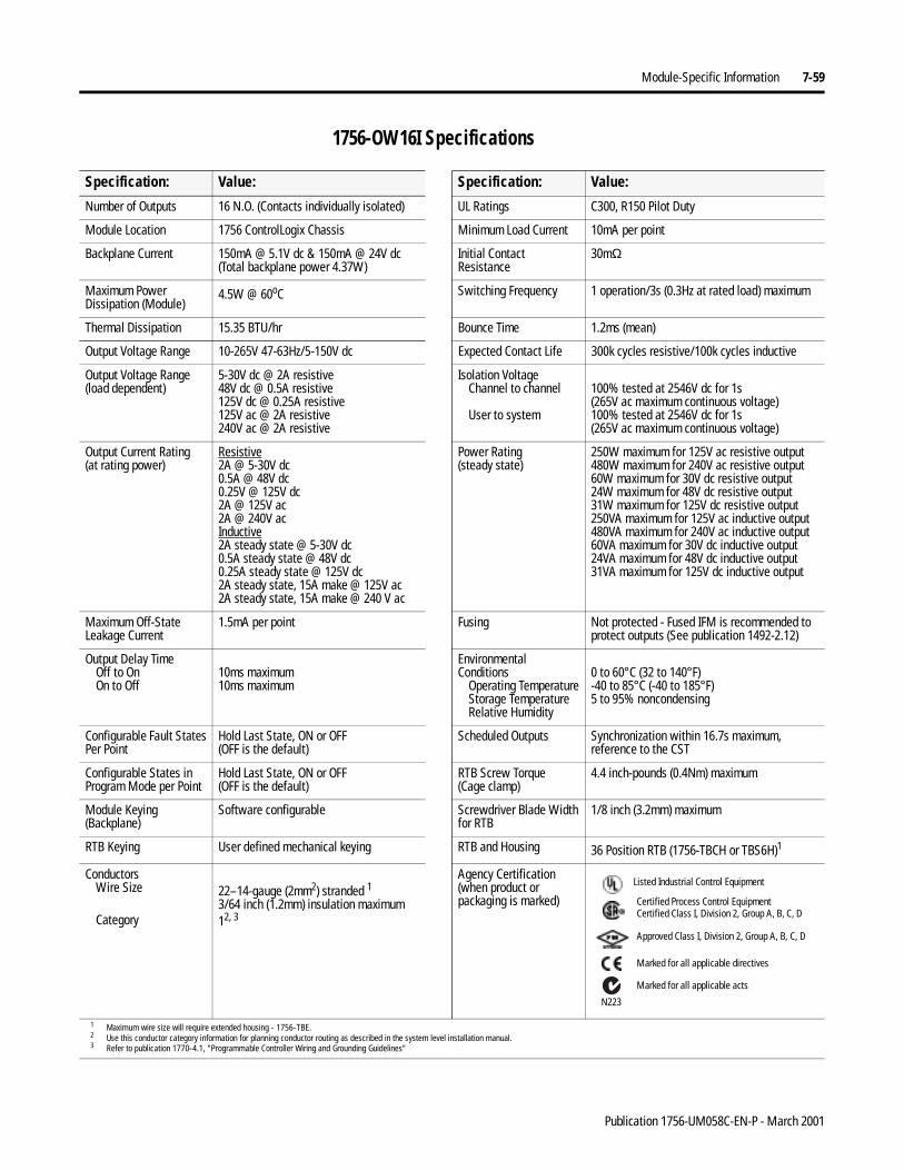
Module-Specific Information 7-59
1756-OW16I Specifications
Specification: Value: Specification: Value:
Number of Outputs 16 N.O. (Contacts individually isolated) UL Ratings C300, R150 Pilot Duty
Module Location 1756 ControlLogix Chassis Minimum Load Current 10mA per point
Backplane Current 150mA @ 5.1V dc & 150mA @ 24V dc(Total backplane power 4.37W)
Initial Contact Resistance
30mΩ
Maximum Power Dissipation (Module)
4.5W @ 60oC Switching Frequency 1 operation/3s (0.3Hz at rated load) maximum
Thermal Dissipation 15.35 BTU/hr Bounce Time 1.2ms (mean)
Output Voltage Range 10-265V 47-63Hz/5-150V dc Expected Contact Life 300k cycles resistive/100k cycles inductive
Output Voltage Range(load dependent)
5-30V dc @ 2A resistive48V dc @ 0.5A resistive125V dc @ 0.25A resistive125V ac @ 2A resistive240V ac @ 2A resistive
Isolation VoltageChannel to channel
User to system
100% tested at 2546V dc for 1s(265V ac maximum continuous voltage)100% tested at 2546V dc for 1s(265V ac maximum continuous voltage)
Output Current Rating(at rating power)
Resistive2A @ 5-30V dc0.5A @ 48V dc0.25V @ 125V dc2A @ 125V ac2A @ 240V acInductive2A steady state @ 5-30V dc0.5A steady state @ 48V dc0.25A steady state @ 125V dc2A steady state, 15A make @ 125V ac2A steady state, 15A make @ 240 V ac
Power Rating(steady state)
250W maximum for 125V ac resistive output480W maximum for 240V ac resistive output60W maximum for 30V dc resistive output24W maximum for 48V dc resistive output31W maximum for 125V dc resistive output250VA maximum for 125V ac inductive output480VA maximum for 240V ac inductive output60VA maximum for 30V dc inductive output24VA maximum for 48V dc inductive output31VA maximum for 125V dc inductive output
Maximum Off-StateLeakage Current
1.5mA per point Fusing Not protected - Fused IFM is recommended to protect outputs (See publication 1492-2.12)
Output Delay TimeOff to OnOn to Off
10ms maximum10ms maximum
Environmental Conditions
Operating TemperatureStorage TemperatureRelative Humidity
0 to 60°C (32 to 140°F)-40 to 85°C (-40 to 185°F)5 to 95% noncondensing
Configurable Fault StatesPer Point
Hold Last State, ON or OFF(OFF is the default)
Scheduled Outputs Synchronization within 16.7s maximum, reference to the CST
Configurable States in Program Mode per Point
Hold Last State, ON or OFF(OFF is the default)
RTB Screw Torque(Cage clamp)
4.4 inch-pounds (0.4Nm) maximum
Module Keying (Backplane)
Software configurable Screwdriver Blade Widthfor RTB
1/8 inch (3.2mm) maximum
RTB Keying User defined mechanical keying RTB and Housing 36 Position RTB (1756-TBCH or TBS6H)1
ConductorsWire Size
Category
22–14-gauge (2mm2) stranded 13/64 inch (1.2mm) insulation maximum12, 3
Agency Certification(when product or packaging is marked)
1 Maximum wire size will require extended housing - 1756-TBE.2 Use this conductor category information for planning conductor routing as described in the system level installation manual.3 Refer to publication 1770-4.1, "Programmable Controller Wiring and Grounding Guidelines”
Marked for all applicable directives
Approved Class I, Division 2, Group A, B, C, D
Certified Process Control EquipmentCertified Class I, Division 2, Group A, B, C, D
Marked for all applicable acts
N223
Listed Industrial Control Equipment
Publication 1756-UM058C-EN-P - March 2001
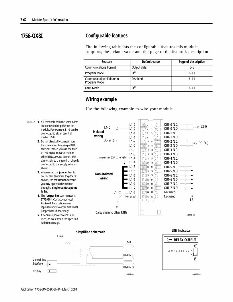
7-60 Module-Specific Information
1756-OX8I Configurable features
The following table lists the configurable features this module supports, the default value and the page of the feature’s description:
Wiring example
Use the following example to wire your module.
Feature Default value Page of description
Communications Format Output data 6-6
Program Mode Off 6-11
Communications Failure in Program Mode
Disabled 6-11
Fault Mode Off 6-11
12
34
56
78
910
1112
1314
1516
1718
1920
2122
2324
2526
2728
2930
3132
3334
3536
L1-0
L1-5
L1-0
L1-5
L1-1
L1-4
L1-3
L1-1
L1-3
L1-2
L1-4
L1-2
L1-7L1-7
L1-7
L1-6L1-6
OUT-0 N.C.
OUT-4 N.C.
OUT-2 N.O.
OUT-3 N.O.
OUT-4 N.O.OUT-5 N.C.OUT-5 N.O.OUT-6 N.C.OUT-6 N.O.OUT-7 N.C.OUT-7 N.O.
OUT-2 N.C.
OUT-3 N.C.
Not usedNot used
Non-isolated wiring
Isolatedwiring
L1
L2
L2-0
DC-2(-)
Not used
OUT-0 N.O.OUT-1 N.C.OUT-1 N.O.
DC-2(+)
L1-0
30241-M
1. All terminals with the same name are connected together on the module. For example, L1-0 can be connected to either terminal marked L1-0.
2. Do not physically connect more than two wires to a single RTB terminal. When you use the third L1-7 terminal to daisy chain to other RTBs, always connect the daisy chain to the terminal directly connected to the supply wire, as shown.
3. When using the jumper bar to daisy chain terminals together as shown, the maximum current you may apply to the module through a single contact point is 8A.
4. The jumper bar part number is 97739201. Contact your local Rockwell Automation sales representative to order additional jumper bars, if necessary.
5. If separate power sources are used, do not exceed the specified isolation voltage.
NOTES:
Daisy chain to other RTBs
Jumper bar (Cut to length)
40456-M
ST 0 1 2 3 4 5 6 7 OK
RELAY OUTPUT
30344-M
Control Bus Interface
+24V
Display
L1-0
OUT-0 N.C.
OUT-0 N.O.
LED indicatorSimplified schematic
Publication 1756-UM058C-EN-P - March 2001
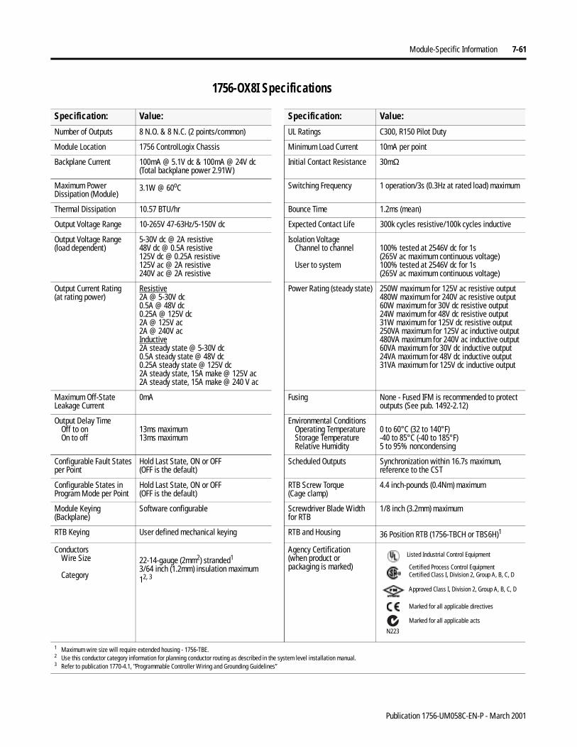
Module-Specific Information 7-61
1756-OX8I Specifications
Specification: Value: Specification: Value:
Number of Outputs 8 N.O. & 8 N.C. (2 points/common) UL Ratings C300, R150 Pilot Duty
Module Location 1756 ControlLogix Chassis Minimum Load Current 10mA per point
Backplane Current 100mA @ 5.1V dc & 100mA @ 24V dc(Total backplane power 2.91W)
Initial Contact Resistance 30mΩ
Maximum Power Dissipation (Module)
3.1W @ 60oC Switching Frequency 1 operation/3s (0.3Hz at rated load) maximum
Thermal Dissipation 10.57 BTU/hr Bounce Time 1.2ms (mean)
Output Voltage Range 10-265V 47-63Hz/5-150V dc Expected Contact Life 300k cycles resistive/100k cycles inductive
Output Voltage Range(load dependent)
5-30V dc @ 2A resistive48V dc @ 0.5A resistive125V dc @ 0.25A resistive125V ac @ 2A resistive240V ac @ 2A resistive
Isolation VoltageChannel to channel
User to system
100% tested at 2546V dc for 1s(265V ac maximum continuous voltage)100% tested at 2546V dc for 1s(265V ac maximum continuous voltage)
Output Current Rating(at rating power)
Resistive2A @ 5-30V dc0.5A @ 48V dc0.25A @ 125V dc2A @ 125V ac2A @ 240V acInductive2A steady state @ 5-30V dc0.5A steady state @ 48V dc0.25A steady state @ 125V dc2A steady state, 15A make @ 125V ac2A steady state, 15A make @ 240 V ac
Power Rating (steady state)
250W maximum for 125V ac resistive output480W maximum for 240V ac resistive output60W maximum for 30V dc resistive output24W maximum for 48V dc resistive output31W maximum for 125V dc resistive output250VA maximum for 125V ac inductive output480VA maximum for 240V ac inductive output60VA maximum for 30V dc inductive output24VA maximum for 48V dc inductive output31VA maximum for 125V dc inductive output
Maximum Off-State Leakage Current
0mA Fusing None - Fused IFM is recommended to protect outputs (See pub. 1492-2.12)
Output Delay TimeOff to onOn to off
13ms maximum13ms maximum
Environmental ConditionsOperating TemperatureStorage TemperatureRelative Humidity
0 to 60°C (32 to 140°F)-40 to 85°C (-40 to 185°F)5 to 95% noncondensing
Configurable Fault Statesper Point
Hold Last State, ON or OFF(OFF is the default)
Scheduled Outputs Synchronization within 16.7s maximum, reference to the CST
Configurable States in Program Mode per Point
Hold Last State, ON or OFF(OFF is the default)
RTB Screw Torque(Cage clamp)
4.4 inch-pounds (0.4Nm) maximum
Module Keying (Backplane)
Software configurable Screwdriver Blade Widthfor RTB
1/8 inch (3.2mm) maximum
RTB Keying User defined mechanical keying RTB and Housing 36 Position RTB (1756-TBCH or TBS6H)1
ConductorsWire Size
Category
22-14-gauge (2mm2) stranded1
3/64 inch (1.2mm) insulation maximum12, 3
Agency Certification(when product or packaging is marked)
1 Maximum wire size will require extended housing - 1756-TBE.2 Use this conductor category information for planning conductor routing as described in the system level installation manual.3 Refer to publication 1770-4.1, "Programmable Controller Wiring and Grounding Guidelines”
Marked for all applicable directives
Approved Class I, Division 2, Group A, B, C, D
Certified Process Control EquipmentCertified Class I, Division 2, Group A, B, C, D
Marked for all applicable acts
N223
Listed Industrial Control Equipment
Publication 1756-UM058C-EN-P - March 2001

7-62 Module-Specific Information
Chapter Summary andWhat’s Next
In this chapter you learned about module specific information. Move on to Chapter 8, Troubleshooting Your Module.
Publication 1756-UM058C-EN-P - March 2001
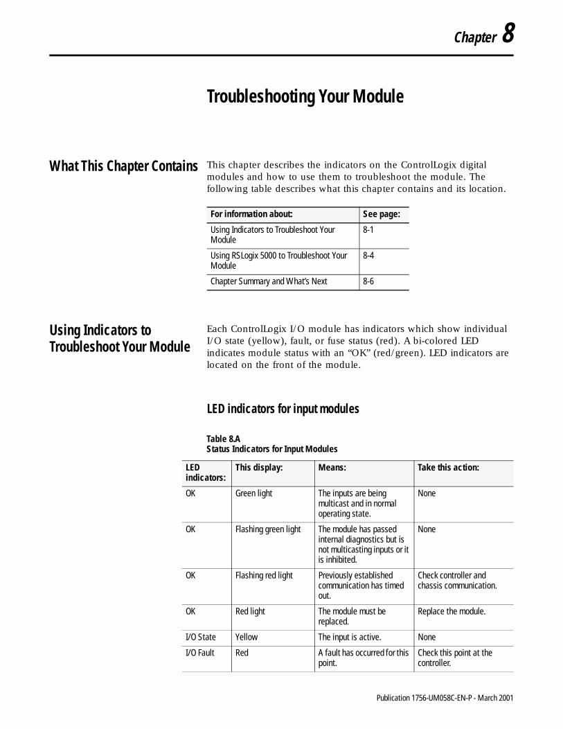
Chapter 8
Troubleshooting Your Module
What This Chapter Contains This chapter describes the indicators on the ControlLogix digital modules and how to use them to troubleshoot the module. The following table describes what this chapter contains and its location.
Using Indicators to Troubleshoot Your Module
Each ControlLogix I/O module has indicators which show individual I/O state (yellow), fault, or fuse status (red). A bi-colored LED indicates module status with an “OK” (red/green). LED indicators are located on the front of the module.
LED indicators for input modules
For information about: See page:
Using Indicators to Troubleshoot Your Module
8-1
Using RSLogix 5000 to Troubleshoot Your Module
8-4
Chapter Summary and What’s Next 8-6
Table 8.A Status Indicators for Input Modules
LED indicators:
This display: Means: Take this action:
OK Green light The inputs are being multicast and in normal operating state.
None
OK Flashing green light The module has passed internal diagnostics but is not multicasting inputs or it is inhibited.
None
OK Flashing red light Previously established communication has timed out.
Check controller and chassis communication.
OK Red light The module must be replaced.
Replace the module.
I/O State Yellow The input is active. None
I/O Fault Red A fault has occurred for this point.
Check this point at the controller.
1 Publication 1756-UM058C-EN-P - March 2001
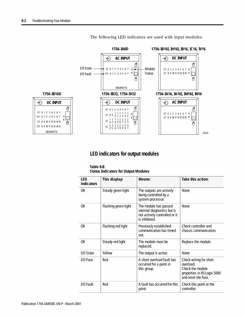
8-2 Troubleshooting Your Module
The following LED indicators are used with input modules:
LED indicators for output modules
1756-IA8D
1756-IB32, 1756-IV32 1756-IA16, IA16I, IM16I, IN16
20945
1756-IB16I, IH16I, IB16, IC16, IV16
1756-IB16D
AC INPUT
ST
FLT
0 1 2 3 4 5 6 7
DC INPUT
0 1 2 3 4 5 6 7
OK
ST 0 1 2 3 4 5 6 7
ST 8 9 10 11 12 13 14 15
OK
FLT 8 9 10 11 12 13 14 15
ST 0 1 2 3 4 5 6 7
ST 8 9 10 11 12 13 14 15
OK
FLT 0 1 2 3 4 5 6 7
DC INPUT DC INPUT
OK
ST 0 1 2 3 4 5 6 7
ST 8 910 21 3 4 5
1 1 1 11
ST 6 718 09 1 2 3
1 2 2 221 1
ST 4 526 87 9 0 1
2 2 2 332 2
DIAGNOSTIC
DIAGNOSTIC
I/O State
I/O FaultModule Status
ST 0 1 2 3 4 5 6 7
ST 8 9 10 11 12 13 1415
OK
AC INPUT
Table 8.B Status Indicators for Output Modules
LED indicators
This display: Means: Take this action:
OK Steady green light The outputs are actively being controlled by a system processor.
None
OK Flashing green light The module has passed internal diagnostics but is not actively controlled or it is inhibited.
None
OK Flashing red light Previously established communication has timed out.
Check controller and chassis communication.
OK Steady red light The module must be replaced.
Replace the module.
I/O State Yellow The output is active. None
I/O Fuse Red A short overload fault has occurred for a point inthis group.
Check wiring for short overload.Check the module properties in RSLogix 5000 and reset the fuse.
I/O Fault Red A fault has occurred for this point.
Check this point at the controller.
Publication 1756-UM058C-EN-P - March 2001
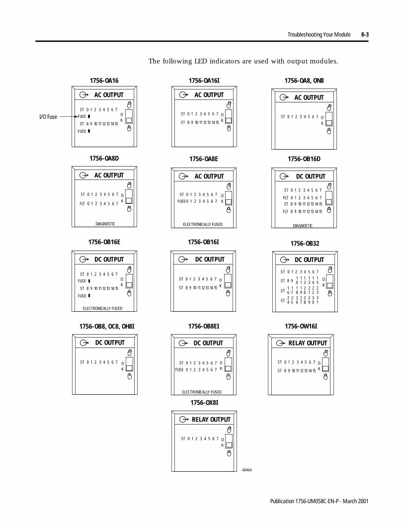
Troubleshooting Your Module 8-3
The following LED indicators are used with output modules.
1756-OA16
AC OUTPUT
ST 0 1 2 3 4 5 6 7
ST 8 9 10 11 12 13 14 15
OK
FUSE
FUSE
DIAGNOSTIC
ST 0 1 2 3 4 5 6 7
ST 8 9 10 11 12 13 14 15
OK
AC OUTPUT
1756-OA16I
ST 0 1 2 3 4 5 6 7 OK
AC OUTPUT
1756-OA8, ON8
ST 0 1 2 3 4 5 6 7 OK
AC OUTPUT
1756-OA8D
FLT 0 1 2 3 4 5 6 7
1756-OA8E
ST 0 1 2 3 4 5 6 7
FUSE0 1 2 3 4 5 6 7OK
AC OUTPUT
ELECTRONICALLY FUSED
1756-OB16D
ST 0 1 2 3 4 5 6 7
FLT 0 1 2 3 4 5 6 7
DIAGNOSTIC
ST 8 9 10 11 12 13 14 15
FLT 8 9 10 11 12 13 14 15
DC OUTPUT
40464
1756-OB32
DC OUTPUT
OK
ST 0 1 2 3 4 5 6 7
ST 8 910 21 3 4 5
1 1 1 11
ST 6 718 09 1 2 3
1 2 2 221 1
ST 4 526 87 9 0 1
2 2 2 332 2
1756-OB16E
DC OUTPUT
ST 0 1 2 3 4 5 6 7
ST 8 9 10 11 12 13 14 15
OK
FUSE
FUSE
ELECTRONICALLY FUSED
DC OUTPUT
1756-OB16I
ST 0 1 2 3 4 5 6 7
ST 8 9 10 11 12 13 14 15
OK
DC OUTPUT
ST 0 1 2 3 4 5 6 7 OK
1756-OB8, OC8, OH8I 1756-OB8EI
DC OUTPUT
ST 0 1 2 3 4 5 6 7 OKFUSE
ELECTRONICALLY FUSED
0 1 2 3 4 5 6 7
ST 0 1 2 3 4 5 6 7
ST 8 9 10 11 12 13 14 15
OK
RELAY OUTPUT
1756-OW16I
ST 0 1 2 3 4 5 6 7 OK
RELAY OUTPUT
1756-OX8I
I/O Fuse
Publication 1756-UM058C-EN-P - March 2001
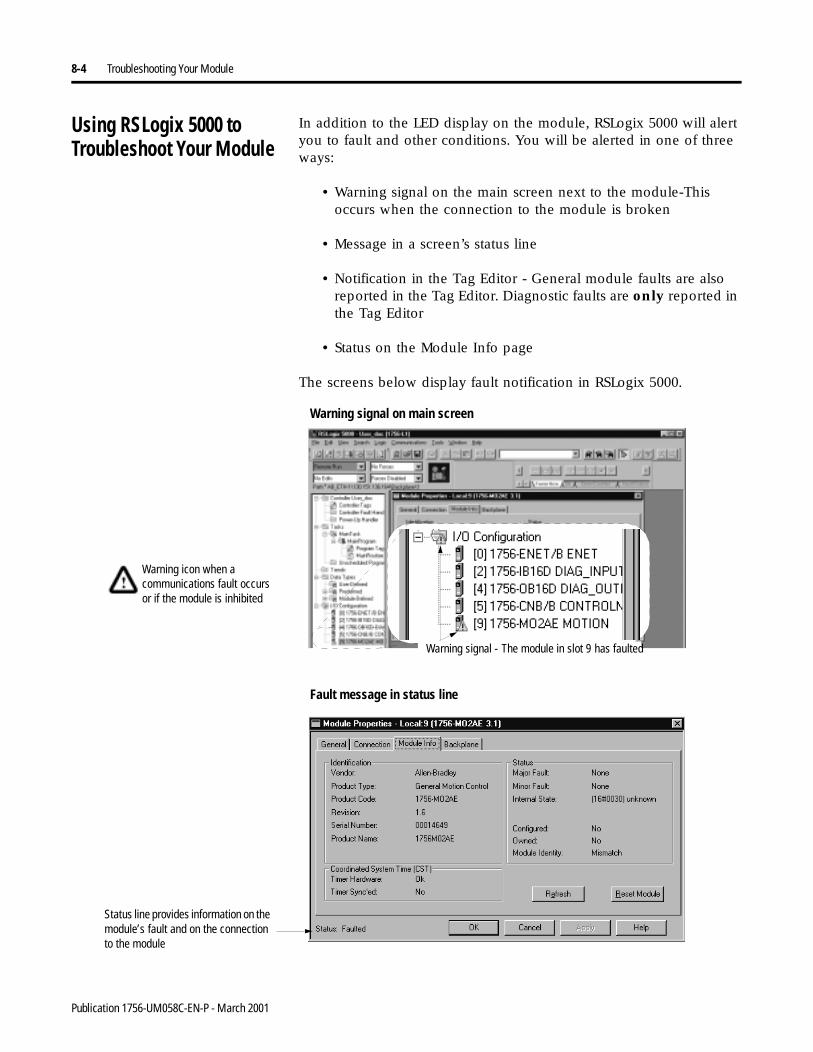
8-4 Troubleshooting Your Module
Using RSLogix 5000 to Troubleshoot Your Module
In addition to the LED display on the module, RSLogix 5000 will alert you to fault and other conditions. You will be alerted in one of three ways:
• Warning signal on the main screen next to the module-This occurs when the connection to the module is broken
• Message in a screen’s status line
• Notification in the Tag Editor - General module faults are also reported in the Tag Editor. Diagnostic faults are only reported in the Tag Editor
• Status on the Module Info page
The screens below display fault notification in RSLogix 5000.
Warning signal on main screen
Warning icon when a communications fault occurs or if the module is inhibited
Warning signal - The module in slot 9 has faulted
Fault message in status line
Status line provides information on the module’s fault and on the connection to the module
Publication 1756-UM058C-EN-P - March 2001
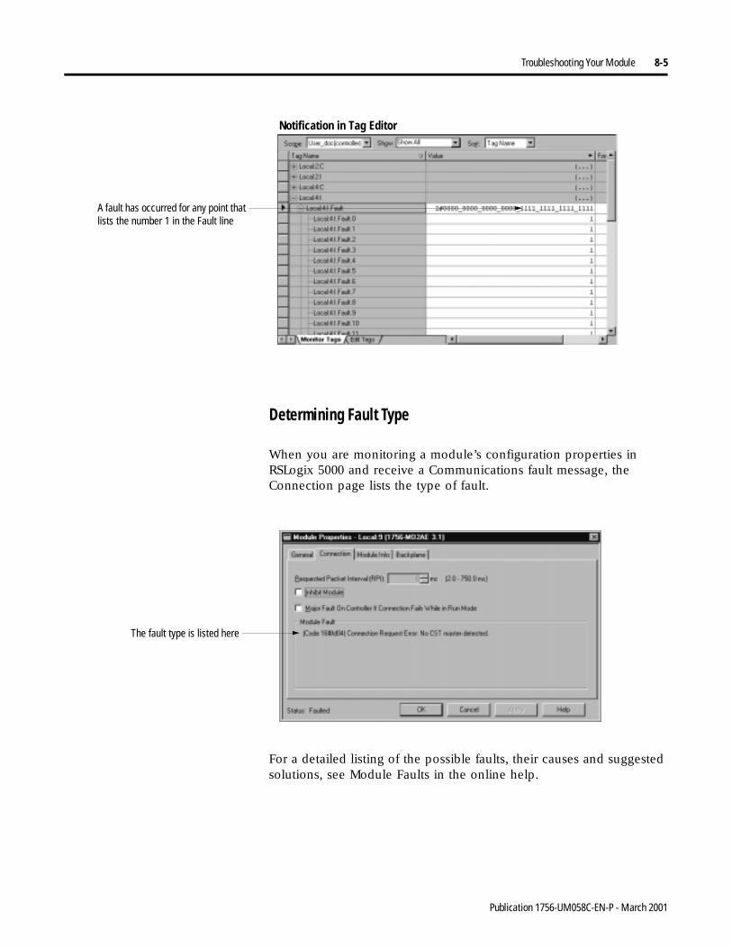
Troubleshooting Your Module 8-5
Determining Fault Type
When you are monitoring a module’s configuration properties inRSLogix 5000 and receive a Communications fault message, the Connection page lists the type of fault.
For a detailed listing of the possible faults, their causes and suggested solutions, see Module Faults in the online help.
Notification in Tag Editor
A fault has occurred for any point that lists the number 1 in the Fault line
The fault type is listed here
Publication 1756-UM058C-EN-P - March 2001

8-6 Troubleshooting Your Module
Chapter Summary andWhat’s Next
In this chapter you learned about troubleshooting the module.
Move on to Appendix A, Using Software Configuration Tags.
Publication 1756-UM058C-EN-P - March 2001
Appendix A
Using Software Configuration Tags
When you create a module, module-defined data types and tags are created. These Tags allow you to access the Input and Output Data and Configuration of Data of the module via the controller’s ladder logic.
The types of tags created vary for each module. There is also variation among the tags for any particular module, depending on which communications format you chose when creating a module.
For example, the 1756-IA16I module has four choices of Communications Formats: Input Data, CST Timestamped Input Data, Listen-Only Input Data, Listen-Only CST Timestamped Input Data. If you choose CST Timestamped Input Data, several more tags are created than if you choose Input Data.
IMPORTANT Although this appendix presents the option of changing a module’s configuration through the Tag Editor of RSLogix 5000, we suggest that you use the module’s properties tabs to change configuration when possible.
1 Publication 1756-UM058C-EN-P - March 2001
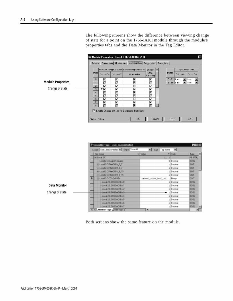
A-2 Using Software Configuration Tags
The following screens show the difference between viewing change of state for a point on the 1756-IA16I module through the module’s properties tabs and the Data Monitor in the Tag Editor.
Both screens show the same feature on the module.
Change of state
Change of state
Module Properties
Data Monitor
Publication 1756-UM058C-EN-P - March 2001
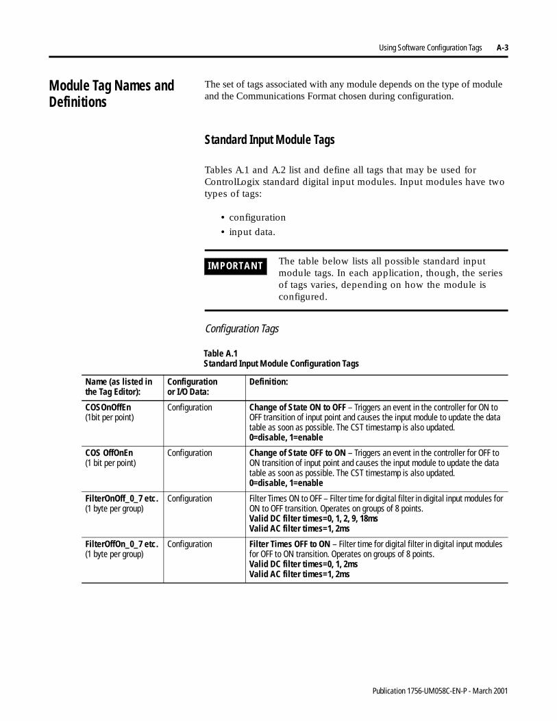
Using Software Configuration Tags A-3
Module Tag Names and Definitions
The set of tags associated with any module depends on the type of module and the Communications Format chosen during configuration.
Standard Input Module Tags
Tables A.1 and A.2 list and define all tags that may be used for ControlLogix standard digital input modules. Input modules have two types of tags:
• configuration
• input data.
Configuration Tags
IMPORTANT The table below lists all possible standard input module tags. In each application, though, the series of tags varies, depending on how the module is configured.
Table A.1 Standard Input Module Configuration Tags
Name (as listed inthe Tag Editor):
Configurationor I/O Data:
Definition:
COSOnOffEn(1bit per point)
Configuration Change of State ON to OFF – Triggers an event in the controller for ON to OFF transition of input point and causes the input module to update the data table as soon as possible. The CST timestamp is also updated.0=disable, 1=enable
COS OffOnEn(1 bit per point)
Configuration Change of State OFF to ON – Triggers an event in the controller for OFF to ON transition of input point and causes the input module to update the data table as soon as possible. The CST timestamp is also updated.0=disable, 1=enable
FilterOnOff_0_7 etc.(1 byte per group)
Configuration Filter Times ON to OFF – Filter time for digital filter in digital input modules for ON to OFF transition. Operates on groups of 8 points.Valid DC filter times=0, 1, 2, 9, 18msValid AC filter times=1, 2ms
FilterOffOn_0_7 etc.(1 byte per group)
Configuration Filter Times OFF to ON – Filter time for digital filter in digital input modules for OFF to ON transition. Operates on groups of 8 points.Valid DC filter times=0, 1, 2msValid AC filter times=1, 2ms
Publication 1756-UM058C-EN-P - March 2001
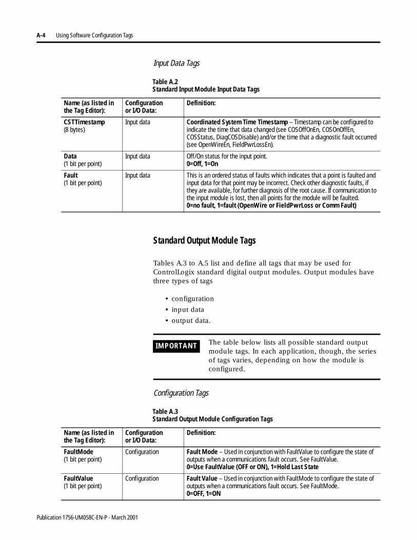
A-4 Using Software Configuration Tags
Input Data Tags
Standard Output Module Tags
Tables A.3 to A.5 list and define all tags that may be used for ControlLogix standard digital output modules. Output modules have three types of tags
• configuration
• input data
• output data.
Configuration Tags
Table A.2 Standard Input Module Input Data Tags
Name (as listed inthe Tag Editor):
Configurationor I/O Data:
Definition:
CSTTimestamp(8 bytes)
Input data Coordinated System Time Timestamp – Timestamp can be configured to indicate the time that data changed (see COSOffOnEn, COSOnOffEn, COSStatus, DiagCOSDisable) and/or the time that a diagnostic fault occurred (see OpenWireEn, FieldPwrLossEn).
Data(1 bit per point)
Input data Off/On status for the input point.0=Off, 1=On
Fault(1 bit per point)
Input data This is an ordered status of faults which indicates that a point is faulted and input data for that point may be incorrect. Check other diagnostic faults, if they are available, for further diagnosis of the root cause. If communication to the input module is lost, then all points for the module will be faulted.0=no fault, 1=fault (OpenWire or FieldPwrLoss or Comm Fault)
IMPORTANT The table below lists all possible standard output module tags. In each application, though, the series of tags varies, depending on how the module is configured.
Table A.3 Standard Output Module Configuration Tags
Name (as listed inthe Tag Editor):
Configurationor I/O Data:
Definition:
FaultMode(1 bit per point)
Configuration Fault Mode – Used in conjunction with FaultValue to configure the state of outputs when a communications fault occurs. See FaultValue.0=Use FaultValue (OFF or ON), 1=Hold Last State
FaultValue(1 bit per point)
Configuration Fault Value – Used in conjunction with FaultMode to configure the state of outputs when a communications fault occurs. See FaultMode.0=OFF, 1=ON
Publication 1756-UM058C-EN-P - March 2001

Using Software Configuration Tags A-5
Input Data Tags
ProgMode(1 bit per point)
Configuration Program Mode – Used in conjunction with ProgValue to configure the state of outputs when the controller is in Program Mode. See ProgValue.0=Use ProgValue (OFF or ON), 1=Hold Last State
ProgValue(1 bit per point)
Configuration Program Value – Used in conjunction with ProgMode to configure the state of outputs when the controller is in Program Mode. See ProgMode.0=Off, 1=On
ProgToFaultEn(1 byte per module)
Configuration Program to Fault Transition – Diagnostic enables the transitioning of outputs to FaultMode if a communications failure occurs in Program Mode. Otherwise outputs will remain in ProgramMode. See ProgMode, ProgValue, FaultMode, FaultValue.0=outputs stay in ProgramMode if comm failure1=outputs got to FaultMode if comm failure
Table A.3 Standard Output Module Configuration Tags
Name (as listed inthe Tag Editor):
Configurationor I/O Data:
Definition:
Table A.4 Standard Output Module Input Data Tags
Name (as listed inthe Tag Editor):
Configurationor I/O Data:
Definition:
CSTTimestamp(8 bytes)
Input data Coordinated System Time Timestamp – Timestamp of diagnostic input data including fusing (see BlownFuse, NoLoad, OutputVerifyFault, FieldPwrLoss), which is updated whenever a diagnostic fault occurs or goes away.
Data(1 bit per point)
Input data Data – Off/On status for the output point ECHOED back from the output module. This is used to verify proper communication only No field side verification is done. For field side verification, see OutputVerifyFault.0=Off, 1=On
Fault(1 bit per point)
Input data This is an ordered status of faults which indicates that a point is faulted and I/O data for that point may be incorrect. Check other diagnostic faults, if they are available, for further diagnosis of the root cause. If communication to the input module is lost, then all points for the module will be faulted.0=no fault, 1=fault (FuseBlown, NoLoad, OutputVerifyFault, FieldPwrLoss, or CommFault)
FuseBlown.(1 bit per point)
Input Data Fuse is Blown – An electronic or mechanical fuse has detected a short or overload condition for an output point. All FuseBlown conditions are latched and must be reset by the User.0=no fault, 1=fault
Publication 1756-UM058C-EN-P - March 2001
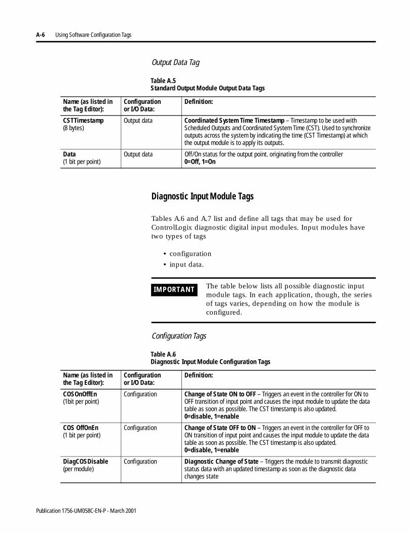
A-6 Using Software Configuration Tags
Output Data Tag
Diagnostic Input Module Tags
Tables A.6 and A.7 list and define all tags that may be used for ControlLogix diagnostic digital input modules. Input modules have two types of tags
• configuration
• input data.
Configuration Tags
Table A.5 Standard Output Module Output Data Tags
Name (as listed inthe Tag Editor):
Configurationor I/O Data:
Definition:
CSTTimestamp(8 bytes)
Output data Coordinated System Time Timestamp – Timestamp to be used with Scheduled Outputs and Coordinated System Time (CST). Used to synchronize outputs across the system by indicating the time (CST Timestamp) at which the output module is to apply its outputs.
Data(1 bit per point)
Output data Off/On status for the output point. originating from the controller0=Off, 1=On
IMPORTANT The table below lists all possible diagnostic input module tags. In each application, though, the series of tags varies, depending on how the module is configured.
Table A.6 Diagnostic Input Module Configuration Tags
Name (as listed inthe Tag Editor):
Configurationor I/O Data:
Definition:
COSOnOffEn(1bit per point)
Configuration Change of State ON to OFF – Triggers an event in the controller for ON to OFF transition of input point and causes the input module to update the data table as soon as possible. The CST timestamp is also updated.0=disable, 1=enable
COS OffOnEn(1 bit per point)
Configuration Change of State OFF to ON – Triggers an event in the controller for OFF to ON transition of input point and causes the input module to update the data table as soon as possible. The CST timestamp is also updated.0=disable, 1=enable
DiagCOSDisable(per module)
Configuration Diagnostic Change of State – Triggers the module to transmit diagnostic status data with an updated timestamp as soon as the diagnostic data changes state
Publication 1756-UM058C-EN-P - March 2001
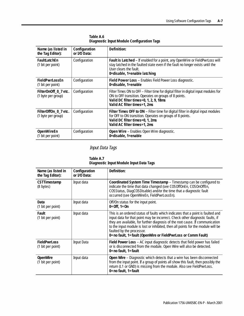
Using Software Configuration Tags A-7
Input Data Tags
FaultLatchEn(1 bit per point)
Configuration Fault is Latched – If enabled for a point, any OpenWire or FieldPwrLoss will stay latched in the faulted state even if the fault no longer exists until the User clears the fault.0=disable, 1=enable latching
FieldPwrLossEn(1 bit per point)
Configuration Field Power Loss – Enables Field Power Loss diagnostic.0=disable, 1=enable
FilterOnOff_0_7 etc.(1 byte per group)
Configuration Filter Times ON to OFF – Filter time for digital filter in digital input modules for ON to OFF transition. Operates on groups of 8 points.Valid DC filter times=0, 1, 2, 9, 18msValid AC filter times=1, 2ms
FilterOffOn_0_7 etc.(1 byte per group)
Configuration Filter Times OFF to ON – Filter time for digital filter in digital input modules for OFF to ON transition. Operates on groups of 8 points.Valid DC filter times=0, 1, 2msValid AC filter times=1, 2ms
OpenWireEn(1 bit per point)
Configuration Open Wire – Enables Open Wire diagnostic.0=disable, 1=enable
Table A.6 Diagnostic Input Module Configuration Tags
Name (as listed inthe Tag Editor):
Configurationor I/O Data:
Definition:
Table A.7 Diagnostic Input Module Input Data Tags
Name (as listed inthe Tag Editor):
Configurationor I/O Data:
Definition:
CSTTimestamp(8 bytes)
Input data Coordinated System Time Timestamp – Timestamp can be configured to indicate the time that data changed (see COSOffOnEn, COSOnOffEn, COSStatus, DiagCOSDisable) and/or the time that a diagnostic fault occurred (see OpenWireEn, FieldPwrLossEn).
Data(1 bit per point)
Input data Off/On status for the input point.0=Off, 1=On
Fault(1 bit per point)
Input data This is an ordered status of faults which indicates that a point is faulted and input data for that point may be incorrect. Check other diagnostic faults, if they are available, for further diagnosis of the root cause. If communication to the input module is lost or inhibited, then all points for the module will be faulted by the processor.0=no fault, 1=fault (OpenWire or FieldPwrLoss or Comm Fault)
FieldPwrLoss(1 bit per point)
Input Data Field Power Loss – AC input diagnostic detects that field power has failed or is disconnected from the module. Open Wire will also be detected.0=no fault, 1=fault
OpenWire(1 bit per point)
Input data Open Wire – Diagnostic which detects that a wire has been disconnected from the input point. If a group of points all show this fault, then possibly the return (L1 or GND) is missing from the module. Also see FieldPwrLoss.0=no fault, 1=fault
Publication 1756-UM058C-EN-P - March 2001
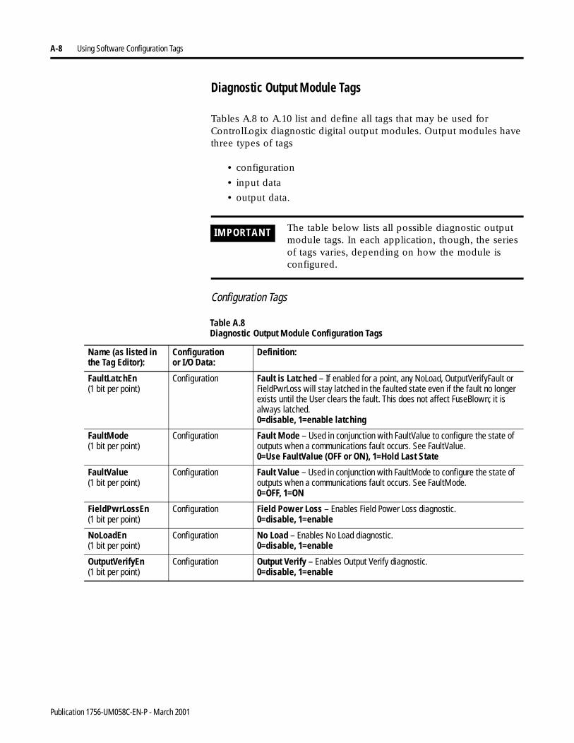
A-8 Using Software Configuration Tags
Diagnostic Output Module Tags
Tables A.8 to A.10 list and define all tags that may be used for ControlLogix diagnostic digital output modules. Output modules have three types of tags
• configuration
• input data
• output data.
Configuration Tags
IMPORTANT The table below lists all possible diagnostic output module tags. In each application, though, the series of tags varies, depending on how the module is configured.
Table A.8 Diagnostic Output Module Configuration Tags
Name (as listed inthe Tag Editor):
Configurationor I/O Data:
Definition:
FaultLatchEn(1 bit per point)
Configuration Fault is Latched – If enabled for a point, any NoLoad, OutputVerifyFault or FieldPwrLoss will stay latched in the faulted state even if the fault no longer exists until the User clears the fault. This does not affect FuseBlown; it is always latched.0=disable, 1=enable latching
FaultMode(1 bit per point)
Configuration Fault Mode – Used in conjunction with FaultValue to configure the state of outputs when a communications fault occurs. See FaultValue.0=Use FaultValue (OFF or ON), 1=Hold Last State
FaultValue(1 bit per point)
Configuration Fault Value – Used in conjunction with FaultMode to configure the state of outputs when a communications fault occurs. See FaultMode.0=OFF, 1=ON
FieldPwrLossEn(1 bit per point)
Configuration Field Power Loss – Enables Field Power Loss diagnostic.0=disable, 1=enable
NoLoadEn(1 bit per point)
Configuration No Load – Enables No Load diagnostic.0=disable, 1=enable
OutputVerifyEn(1 bit per point)
Configuration Output Verify – Enables Output Verify diagnostic.0=disable, 1=enable
Publication 1756-UM058C-EN-P - March 2001
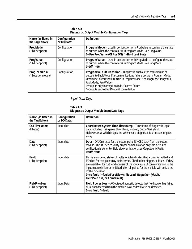
Using Software Configuration Tags A-9
Input Data Tags
ProgMode(1 bit per point)
Configuration Program Mode – Used in conjunction with ProgValue to configure the state of outputs when the controller is in Program Mode. See ProgValue.0=Use ProgValue (OFF or ON), 1=Hold Last State
ProgValue(1 bit per point)
Configuration Program Value – Used in conjunction with ProgMode to configure the state of outputs when the controller is in Program Mode. See ProgMode.0=Off, 1=On
ProgToFaultEn(1 byte per module)
Configuration Program to Fault Transition – Diagnostic enables the transitioning of outputs to FaultMode if a communications failure occurs in Program Mode. Otherwise outputs will remain in ProgramMode. See ProgMode, ProgValue, FaultMode, FaultValue.0=outputs stay in ProgramMode if comm failure1=outputs got to FaultMode if comm failure
Table A.8 Diagnostic Output Module Configuration Tags
Name (as listed inthe Tag Editor):
Configurationor I/O Data:
Definition:
Table A.9 Diagnostic Output Module Input Data Tags
Name (as listed inthe Tag Editor):
Configurationor I/O Data:
Definition:
CSTTimestamp(8 bytes)
Input data Coordinated System Time Timestamp – Timestamp of diagnostic input data including fusing (see BlownFuse, NoLoad, OutputVerifyFault, FieldPwrLoss), which is updated whenever a diagnostic fault occurs or goes away.
Data(1 bit per point)
Input data Data – Off/On status for the output point ECHOED back from the output module. This is used to verify proper communication only No field side verification is done. For field side verification, see OutputVerifyFault.0=Off, 1=On
Fault(1 bit per point)
Input data This is an ordered status of faults which indicates that a point is faulted and I/O data for that point may be incorrect. Check other diagnostic faults, if they are available, for further diagnosis of the root cause. If communication to the input module is lost or inhibited, then all points for the module will be faulted by the processor.0=no fault, 1=fault (FuseBlown, NoLoad, OutputVerifyFault, FieldPwrLoss, or CommFault)
FieldPwrLoss(1 bit per point)
Input Data Field Power Loss – AC output diagnostic detects that field power has failed or is disconnected from the module. No Load will also be detected.0=no fault, 1=fault
Publication 1756-UM058C-EN-P - March 2001
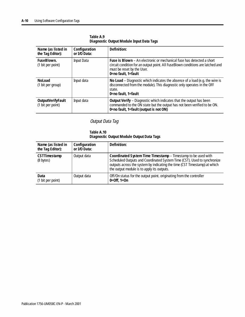
A-10 Using Software Configuration Tags
Output Data Tag
FuseBlown.(1 bit per point)
Input Data Fuse is Blown – An electronic or mechanical fuse has detected a short circuit condition for an output point. All FuseBlown conditions are latched and must be reset by the User.0=no fault, 1=fault
NoLoad(1 bit per group)
Input data No Load – Diagnostic which indicates the absence of a load (e.g. the wire is disconnected from the module). This diagnostic only operates in the OFF state.0=no fault, 1=fault
OutputVerifyFault(1 bit per point)
Input data Output Verify – Diagnostic which indicates that the output has been commanded to the ON state but the output has not been verified to be ON. 0=no fault, 1=fault (output is not ON)
Table A.9 Diagnostic Output Module Input Data Tags
Name (as listed inthe Tag Editor):
Configurationor I/O Data:
Definition:
Table A.10 Diagnostic Output Module Output Data Tags
Name (as listed inthe Tag Editor):
Configurationor I/O Data:
Definition:
CSTTimestamp(8 bytes)
Output data Coordinated System Time Timestamp – Timestamp to be used with Scheduled Outputs and Coordinated System Time (CST). Used to synchronize outputs across the system by indicating the time (CST Timestamp) at which the output module is to apply its outputs.
Data(1 bit per point)
Output data Off/On status for the output point. originating from the controller0=Off, 1=On
Publication 1756-UM058C-EN-P - March 2001
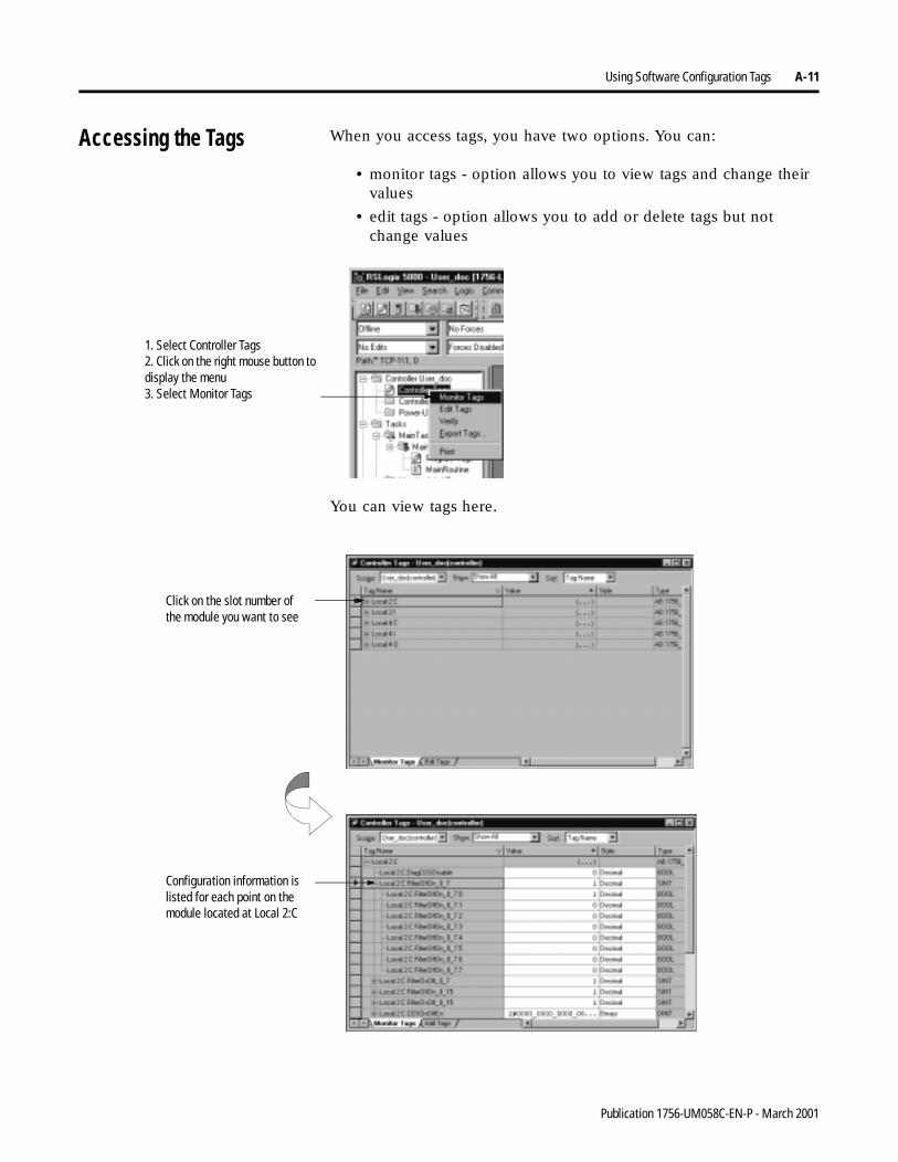
Using Software Configuration Tags A-11
Accessing the Tags When you access tags, you have two options. You can:
• monitor tags - option allows you to view tags and change their values
• edit tags - option allows you to add or delete tags but not change values
You can view tags here.
1. Select Controller Tags2. Click on the right mouse button to display the menu3. Select Monitor Tags
Click on the slot number of the module you want to see
Configuration information is listed for each point on the module located at Local 2:C
Publication 1756-UM058C-EN-P - March 2001
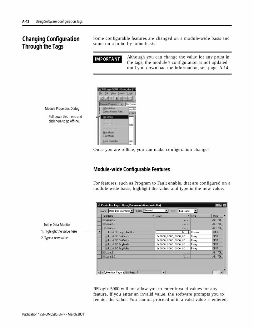
A-12 Using Software Configuration Tags
Changing Configuration Through the Tags
Some configurable features are changed on a module-wide basis and some on a point-by-point basis.
Once you are offline, you can make configuration changes.
Module-wide Configurable Features
For features, such as Program to Fault enable, that are configured on a module-wide basis, highlight the value and type in the new value.
RSLogix 5000 will not allow you to enter invalid values for any feature. If you enter an invalid value, the software prompts you to reenter the value. You cannot proceed until a valid value is entered.
IMPORTANT Although you can change the value for any point in the tags, the module’s configuration is not updated until you download the information, see page A-14.
Pull down this menu and click here to go offline.
Module Properties Dialog
In the Data Monitor
1. Highlight the value here
2. Type a new value
Publication 1756-UM058C-EN-P - March 2001
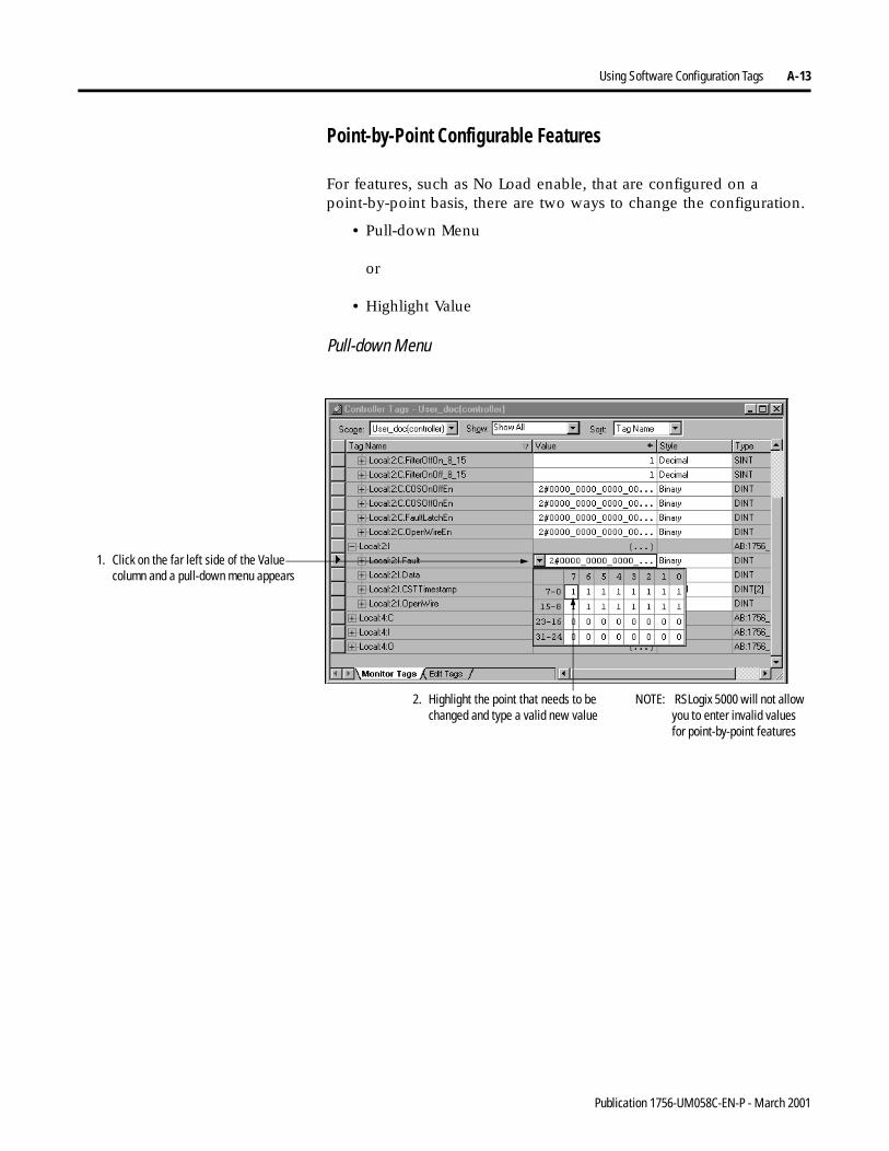
Using Software Configuration Tags A-13
Point-by-Point Configurable Features
For features, such as No Load enable, that are configured on a point-by-point basis, there are two ways to change the configuration.
• Pull-down Menu
or
• Highlight Value
Pull-down Menu
1. Click on the far left side of the Value column and a pull-down menu appears
2. Highlight the point that needs to be changed and type a valid new value
NOTE: RSLogix 5000 will not allow you to enter invalid values for point-by-point features
Publication 1756-UM058C-EN-P - March 2001
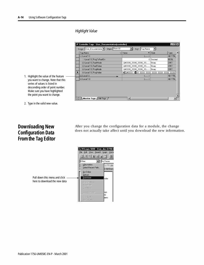
A-14 Using Software Configuration Tags
Highlight Value
Downloading New Configuration DataFrom the Tag Editor
After you change the configuration data for a module, the change does not actually take affect until you download the new information.
1. Highlight the value of the feature you want to change. Note that this series of values is listed in descending order of point number. Make sure you have highlighted the point you want to change.
2. Type in the valid new value.
Pull down this menu and click here to download the new data
Publication 1756-UM058C-EN-P - March 2001
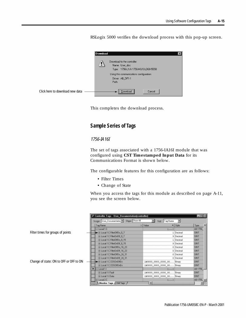
Using Software Configuration Tags A-15
RSLogix 5000 verifies the download process with this pop-up screen.
This completes the download process.
Sample Series of Tags
1756-IA16I
The set of tags associated with a 1756-IA16I module that was configured using CST Timestamped Input Data for its Communications Format is shown below.
The configurable features for this configuration are as follows:
• Filter Times
• Change of State
When you access the tags for this module as described on page A-11, you see the screen below.
Click here to download new data
Change of state: ON to OFF or OFF to ON
Filter times for groups of points
Publication 1756-UM058C-EN-P - March 2001
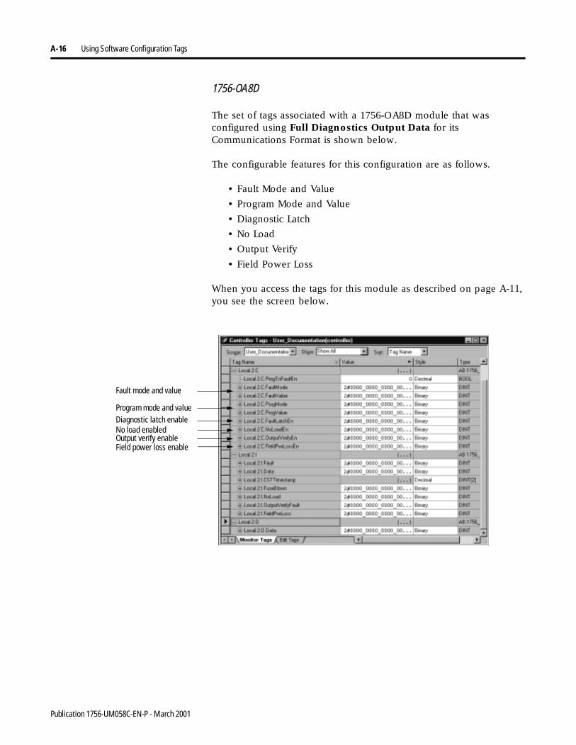
A-16 Using Software Configuration Tags
1756-OA8D
The set of tags associated with a 1756-OA8D module that was configured using Full Diagnostics Output Data for its Communications Format is shown below.
The configurable features for this configuration are as follows.
• Fault Mode and Value
• Program Mode and Value
• Diagnostic Latch
• No Load
• Output Verify
• Field Power Loss
When you access the tags for this module as described on page A-11, you see the screen below.
Fault mode and value
Program mode and valueDiagnostic latch enableNo load enabledOutput verify enableField power loss enable
Publication 1756-UM058C-EN-P - March 2001
Appendix B
Using Ladder Logic
You can use ladder logic to perform run time services on your module. For example, page 6-22 shows how to reset an electronic fuse on the 1756-OA8D module using RSLogix 5000. This appendix provides an example of how to reset the same fuse without using RSLogix 5000.
In addition to performing run time services, you can use ladder logic to change configuration. Chapter 6 explained how to use the RSLogix 5000 software to set configuration parameters in your ControlLogix analog I/O module. Some of those parameters may also be changed through ladder logic.
Using Message Instructions
In ladder logic, you can use Message instructions to send occasional services to any ControlLogix I/O module. Message instructions send an explicit service to the module, causing specific behavior to occur, for example, unlatching a high alarm.
Message instructions maintain the following characteristics:
• messages use unscheduled portions of systemcommunications bandwidth
• one service is performed per instruction
• performing module services does not impede module functionality, such as sampling inputs or applying new outputs
1 Publication 1756-UM058C-EN-P - March 2001
B-2 Using Ladder Logic
Processing Real-Time Control and Module Services
Services sent via message instructions are not as time critical as the module behavior defined during configuration and maintained by a real-time connection. Therefore, the module processes messaging services only after the needs of the I/O connection have been met.
For example, you may want to unlatch all process alarms on the module, but real-time control of your process is still occurring using the input value from that same channel. Because the input value is critical to your application, the module prioritizes the sampling of inputs ahead of the unlatch service request.
This prioritization allows input channels to be sampled at the same frequency and the process alarms to be unlatched in the time between sampling and producing the real-time input data.
One Service Performed Per Instruction
Message instructions will only cause a module service to be performed once per execution. For example, if a message instruction sends a service to the module to unlatch the high high alarm on a particular channel, that channel’s high high alarm will unlatch, but may be set on a subsequent channel sample. The message instruction must then be reexecuted to unlatch the alarm a second time.
Publication 1756-UM058C-EN-P - March 2001
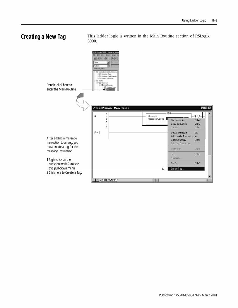
Using Ladder Logic B-3
Creating a New Tag This ladder logic is written in the Main Routine section of RSLogix 5000.
Double-click here to enter the Main Routine
After adding a message instruction to a rung, you must create a tag for the message instruction
1 Right-click on thequestion mark (?) to seethis pull-down menu.
2 Click here to Create a Tag.
Publication 1756-UM058C-EN-P - March 2001
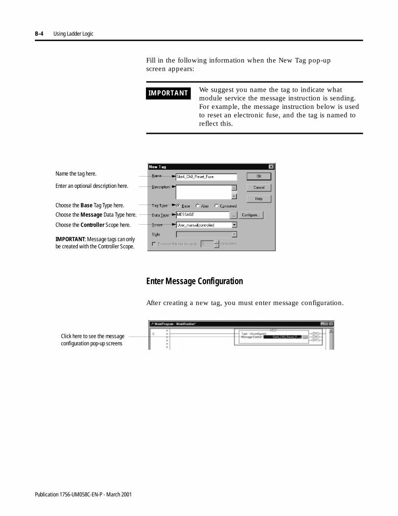
B-4 Using Ladder Logic
Fill in the following information when the New Tag pop-upscreen appears:
Enter Message Configuration
After creating a new tag, you must enter message configuration.
IMPORTANT We suggest you name the tag to indicate what module service the message instruction is sending. For example, the message instruction below is used to reset an electronic fuse, and the tag is named to reflect this.
Name the tag here.
Choose the Base Tag Type here.
Choose the Message Data Type here.
Choose the Controller Scope here.
IMPORTANT: Message tags can only be created with the Controller Scope.
Enter an optional description here.
Click here to see the message configuration pop-up screens
Publication 1756-UM058C-EN-P - March 2001
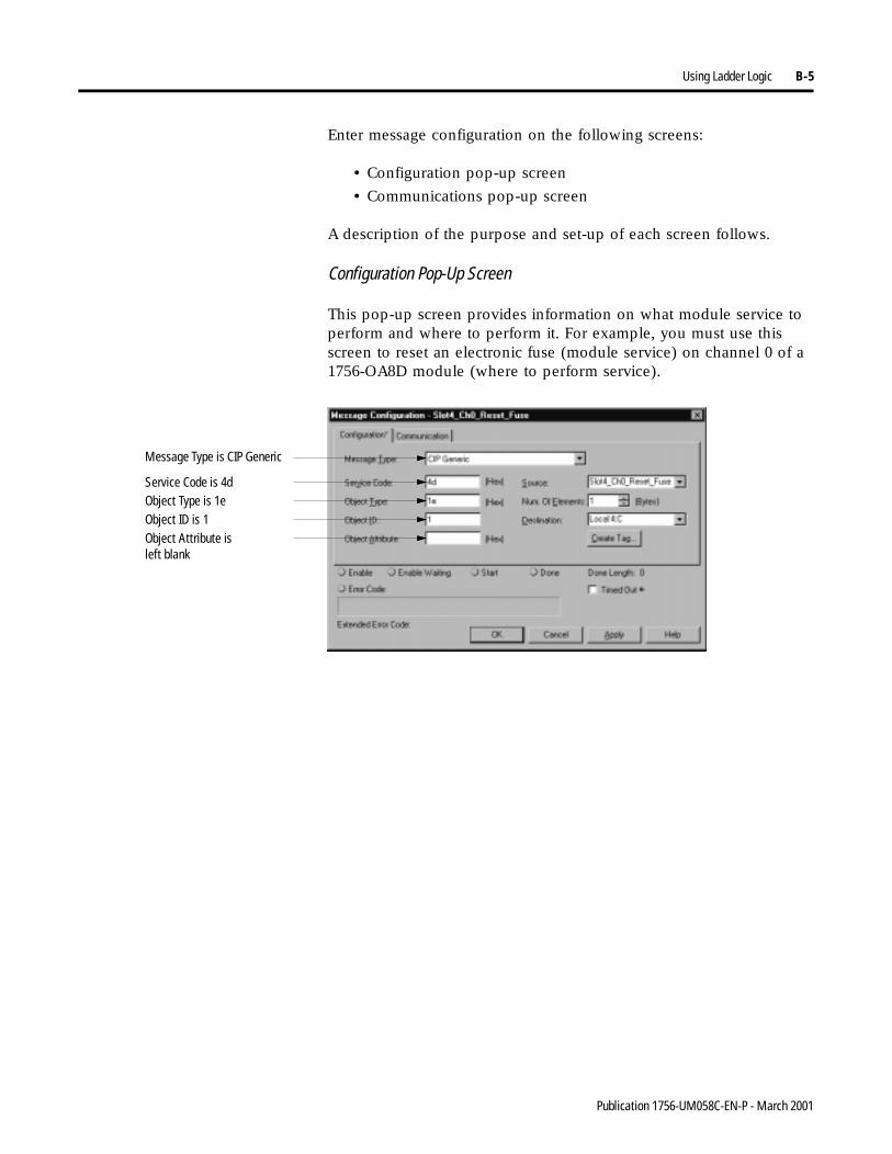
Using Ladder Logic B-5
Enter message configuration on the following screens:
• Configuration pop-up screen
• Communications pop-up screen
A description of the purpose and set-up of each screen follows.
Configuration Pop-Up Screen
This pop-up screen provides information on what module service to perform and where to perform it. For example, you must use this screen to reset an electronic fuse (module service) on channel 0 of a 1756-OA8D module (where to perform service).
Message Type is CIP Generic
Service Code is 4dObject Type is 1eObject ID is 1Object Attribute is left blank
Publication 1756-UM058C-EN-P - March 2001
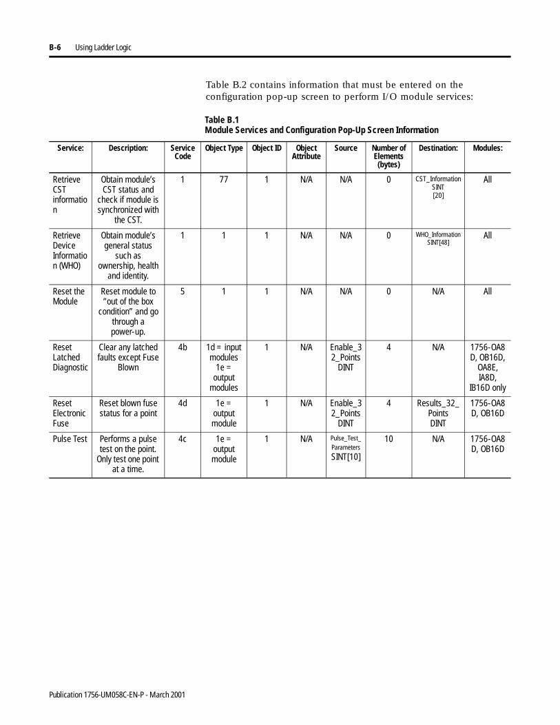
B-6 Using Ladder Logic
Table B.2 contains information that must be entered on the configuration pop-up screen to perform I/O module services:
Table B.1 Module Services and Configuration Pop-Up Screen Information
Service: Description: Service Code
Object Type Object ID Object Attribute
Source Number of Elements(bytes)
Destination: Modules:
Retrieve CST information
Obtain module’s CST status and
check if module is synchronized with
the CST.
1 77 1 N/A N/A 0 CST_Information SINT[20]
All
Retrieve Device Information (WHO)
Obtain module’s general status
such as ownership, health
and identity.
1 1 1 N/A N/A 0 WHO_Information SINT[48]
All
Reset the Module
Reset module to “out of the box
condition” and go through a power-up.
5 1 1 N/A N/A 0 N/A All
Reset Latched Diagnostic
Clear any latched faults except Fuse
Blown
4b 1d = input modules
1e = output
modules
1 N/A Enable_32_Points
DINT
4 N/A 1756-OA8D, OB16D,
OA8E, IA8D,
IB16D only
Reset ElectronicFuse
Reset blown fuse status for a point
4d 1e = output module
1 N/A Enable_32_Points
DINT
4 Results_32_PointsDINT
1756-OA8D, OB16D
Pulse Test Performs a pulse test on the point.
Only test one point at a time.
4c 1e = output module
1 N/A Pulse_Test_Parameters SINT[10]
10 N/A 1756-OA8D, OB16D
Publication 1756-UM058C-EN-P - March 2001
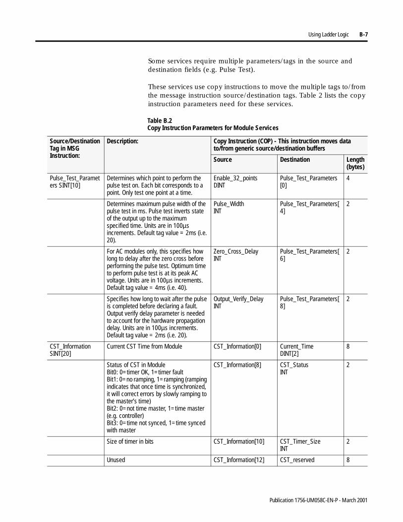
Using Ladder Logic B-7
Some services require multiple parameters/tags in the source and destination fields (e.g. Pulse Test).
These services use copy instructions to move the multiple tags to/from the message instruction source/destination tags. Table 2 lists the copy instruction parameters need for these services.
Table B.2 Copy Instruction Parameters for Module Services
Source/Destination Tag in MSG Instruction:
Description: Copy Instruction (COP) - This instruction moves data to/from generic source/destination buffers
Source Destination Length (bytes)
Pulse_Test_Parameters SINT[10]
Determines which point to perform the pulse test on. Each bit corresponds to a point. Only test one point at a time.
Enable_32_pointsDINT
Pulse_Test_Parameters [0]
4
Determines maximum pulse width of the pulse test in ms. Pulse test inverts state of the output up to the maximum specified time. Units are in 100µs increments. Default tag value = 2ms (i.e. 20).
Pulse_WidthINT
Pulse_Test_Parameters[4]
2
For AC modules only, this specifies how long to delay after the zero cross before performing the pulse test. Optimum time to perform pulse test is at its peak AC voltage. Units are in 100µs increments. Default tag value = 4ms (i.e. 40).
Zero_Cross_DelayINT
Pulse_Test_Parameters[6]
2
Specifies how long to wait after the pulse is completed before declaring a fault. Output verify delay parameter is needed to account for the hardware propagation delay. Units are in 100µs increments. Default tag value = 2ms (i.e. 20).
Output_Verify_DelayINT
Pulse_Test_Parameters[8]
2
CST_InformationSINT[20]
Current CST Time from Module CST_Information[0] Current_TimeDINT[2]
8
Status of CST in ModuleBit0: 0=timer OK, 1=timer faultBit1: 0=no ramping, 1=ramping (ramping indicates that once time is synchronized, it will correct errors by slowly ramping to the master’s time) Bit2: 0=not time master, 1=time master (e.g. controller)Bit3: 0=time not synced, 1=time synced with master
CST_Information[8] CST_StatusINT
2
Size of timer in bits CST_Information[10] CST_Timer_SizeINT
2
Unused CST_Information[12] CST_reserved 8
Publication 1756-UM058C-EN-P - March 2001
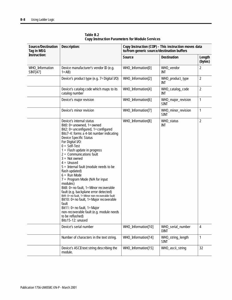
B-8 Using Ladder Logic
WHO_InformationSINT[47]
Device manufacturer’s vendor ID (e.g. 1=AB)
WHO_Information[0] WHO_vendorINT
2
Device’s product type (e.g. 7=Digital I/O) WHO_Information[2] WHO_product_typeINT
2
Device’s catalog code which maps to its catalog number
WHO_Information[4] WHO_catalog_codeINT
2
Device’s major revision WHO_Information[6] WHO_major_revisionSINT
1
Device’s minor revision WHO_Information[7] WHO_minor_revisionSINT
1
Device’s internal statusBit0: 0=unowned, 1=owned Bit2: 0=unconfigured, 1=configuredBits7-4: forms a 4-bit number indicating Device Specific StatusFor Digital I/O:0 = Self-Test1 = Flash update in progress2 = Communications fault3 = Not owned4 = Unused5 = Internal fault (module needs to be flash updated)6 = Run Mode7 = Program Mode (N/A for input modules)Bit8: 0=no fault, 1=Minor recoverable fault (e.g. backplane error detected)Bit9: 0=no fault, 1=Minor non-recoverable faultBit10: 0=no fault, 1=Major recoverable faultBit11: 0=no fault, 1=Major non-recoverable fault (e.g. module needs to be reflashed)Bits15-12: unused
WHO_Information[8] WHO_statusINT
2
Device’s serial number WHO_Information[10] WHO_serial_numberDINT
4
Number of characters in the text string. WHO_Information[14] WHO_string_lengthSINT
1
Device’s ASCII text string describing the module.
WHO_Information[15] WHO_ascii_string 32
Table B.2 Copy Instruction Parameters for Module Services
Source/Destination Tag in MSG Instruction:
Description: Copy Instruction (COP) - This instruction moves data to/from generic source/destination buffers
Source Destination Length (bytes)
Publication 1756-UM058C-EN-P - March 2001
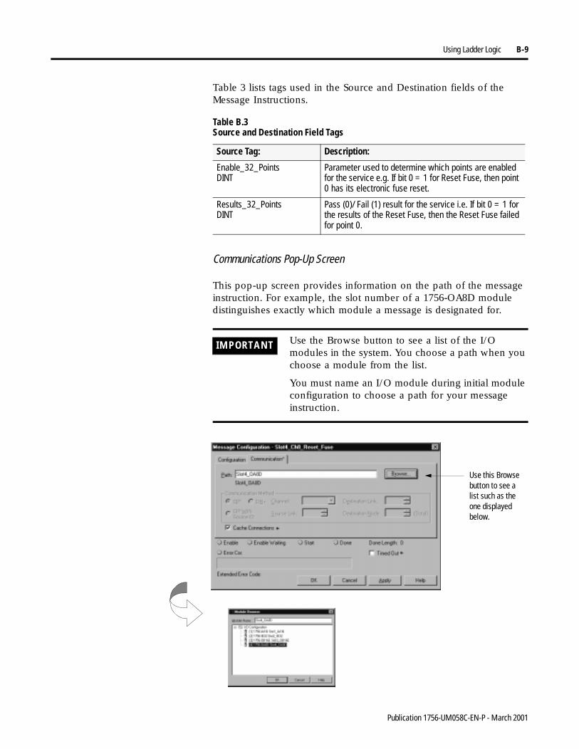
Using Ladder Logic B-9
Table 3 lists tags used in the Source and Destination fields of the Message Instructions.
Communications Pop-Up Screen
This pop-up screen provides information on the path of the message instruction. For example, the slot number of a 1756-OA8D module distinguishes exactly which module a message is designated for.
Table B.3 Source and Destination Field Tags
Source Tag: Description:
Enable_32_PointsDINT
Parameter used to determine which points are enabled for the service e.g. If bit 0 = 1 for Reset Fuse, then point 0 has its electronic fuse reset.
Results_32_PointsDINT
Pass (0)/ Fail (1) result for the service i.e. If bit 0 = 1 for the results of the Reset Fuse, then the Reset Fuse failed for point 0.
IMPORTANT Use the Browse button to see a list of the I/O modules in the system. You choose a path when you choose a module from the list.
You must name an I/O module during initial module configuration to choose a path for your message instruction.
Use this Browse button to see a list such as the one displayed below.
Publication 1756-UM058C-EN-P - March 2001

B-10 Using Ladder Logic
Using Timestamped Inputs and Scheduled Outputs
This example demonstrates the use of timestamped inputs and scheduled outputs for digital I/O. The CST can be utilized to synchronize the output turning OFF to ON based upon the time that the input transitioned OFF to ON. The program can be extended to include synchronizing multiple output modules by sending the same timestamp to all output modules.
For this example, the output will follow the state of the input 0, but it will be delayed by exactly 10ms. The advantage of using CST (over timers) is that the synchronization is being performed at the I/O module which eliminates any jitter due to controller or communication delays.
Your control becomes much more deterministic even under changing loads. For this synchronization to work properly, the 10ms delay must be long enough to account for any controller, backplane, and network delays. The input and output modules must reside in the same rack as a Time Master (i.e. Controller) Timestamp units are µsecs.
Rungs 0 and 1 are used to detect the transition from PROGRAM to RUN mode. This is used to turn ON “init” which causes the program to initialize its tags
Rung 2 only executes once and initializes the LastTimestamp. LastTimestamp is used to detect a Change of State on the input point by checking to see if the timestamp of the input data has changed
Publication 1756-UM058C-EN-P - March 2001
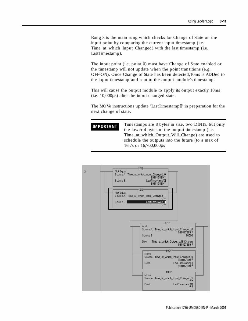
Using Ladder Logic B-11
Rung 3 is the main rung which checks for Change of State on the input point by comparing the current input timestamp (i.e. Time_at_which_Input_Changed) with the last timestamp (i.e. LastTimestamp).
The input point (i.e. point 0) must have Change of State enabled or the timestamp will not update when the point transitions (e.g. OFF-ON). Once Change of State has been detected,10ms is ADDed to the input timestamp and sent to the output module’s timestamp.
This will cause the output module to apply its output exactly 10ms(i.e. 10,000µs) after the input changed state.
The MOVe instructions update "LastTimestamp[]" in preparation for the next change of state.
IMPORTANT Timestamps are 8 bytes in size, two DINTs, but only the lower 4 bytes of the output timestamp (i.e. Time_at_which_Output_Will_Change) are used to schedule the outputs into the future (to a max of 16.7s or 16,700,000µs
Publication 1756-UM058C-EN-P - March 2001
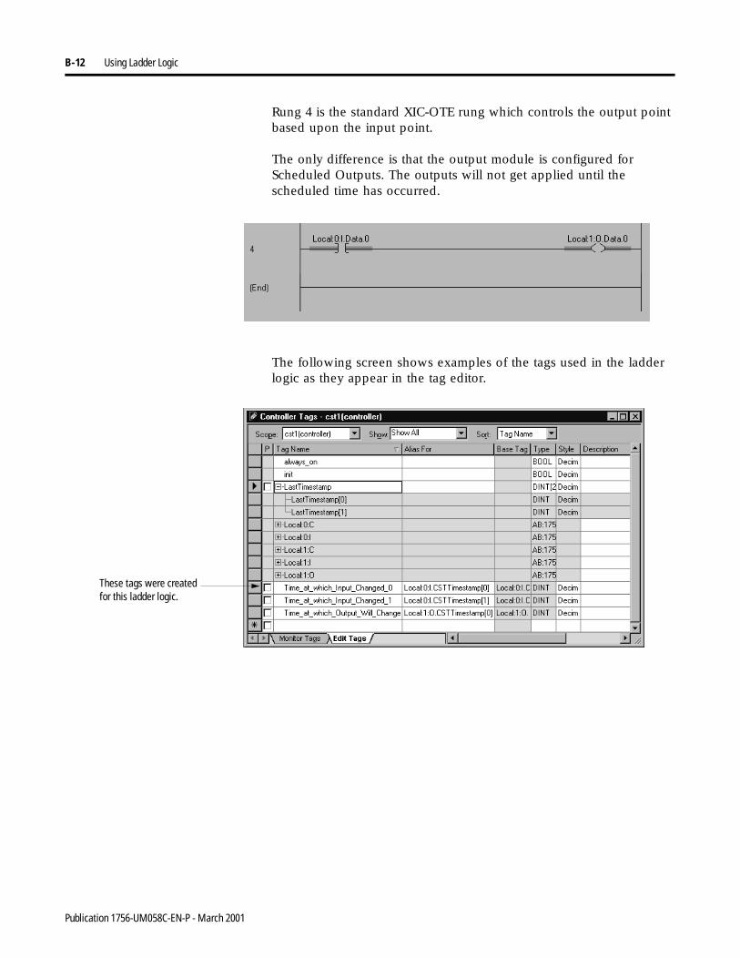
B-12 Using Ladder Logic
Rung 4 is the standard XIC-OTE rung which controls the output point based upon the input point.
The only difference is that the output module is configured for Scheduled Outputs. The outputs will not get applied until the scheduled time has occurred.
The following screen shows examples of the tags used in the ladder logic as they appear in the tag editor.
These tags were created for this ladder logic.
Publication 1756-UM058C-EN-P - March 2001
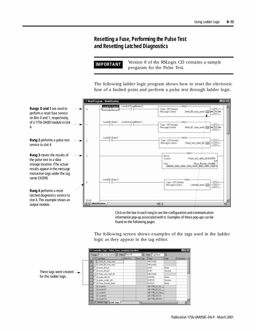
Using Ladder Logic B-13
Resetting a Fuse, Performing the Pulse Testand Resetting Latched Diagnostics
The following ladder logic program shows how to reset the electronic fuse of a faulted point and perform a pulse test through ladder logic.
The following screen shows examples of the tags used in the ladder logic as they appear in the tag editor.
IMPORTANT Version 8 of the RSLogix CD contains a sample progaram for the Pulse Test.
Rungs O and 1 are used to perform a reset fuse service on Bits 0 and 1, respectively, of a 1756-OA8D module in slot 4.
Rung 2 performs a pulse test service to slot 4.
Rung 3 moves the results of the pulse test to a data storage location. (The actual results appear in the message instruction tags under the tag name EXERR)
Rung 4 performs a reset latched diagnostics service to slot 4. This example shows an output module.
Click on the box in each rung to see the configuration and communication information pop-up associated with it. Examples of these pop-ups can be found on the following pages
These tags were created for this ladder logic.
Publication 1756-UM058C-EN-P - March 2001
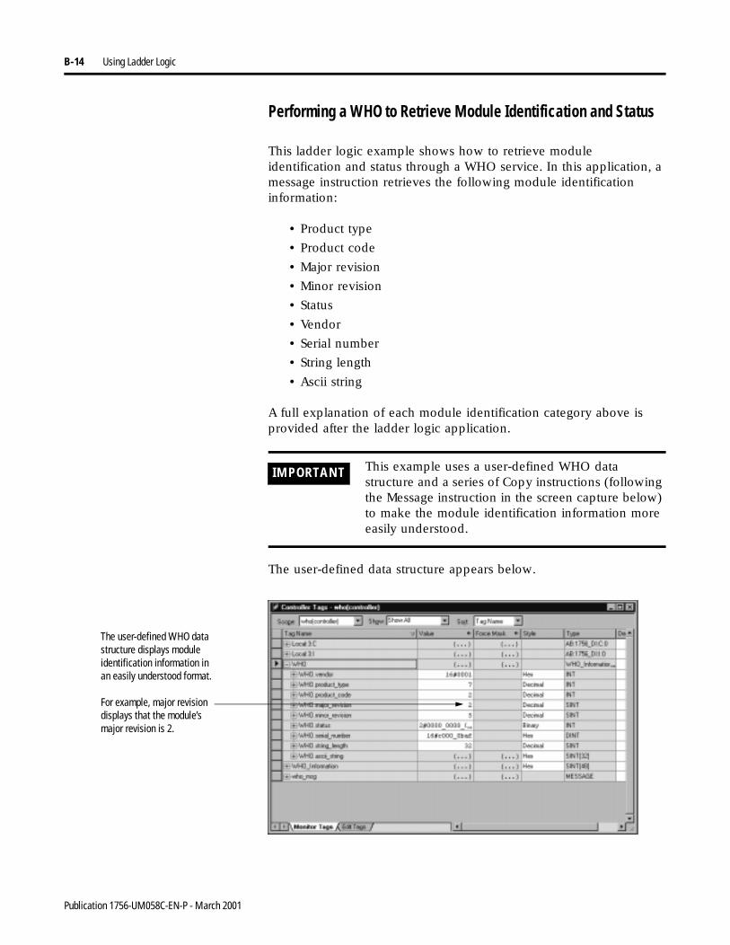
B-14 Using Ladder Logic
Performing a WHO to Retrieve Module Identification and Status
This ladder logic example shows how to retrieve module identification and status through a WHO service. In this application, a message instruction retrieves the following module identification information:
• Product type
• Product code
• Major revision
• Minor revision
• Status
• Vendor
• Serial number
• String length
• Ascii string
A full explanation of each module identification category above is provided after the ladder logic application.
The user-defined data structure appears below.
IMPORTANT This example uses a user-defined WHO data structure and a series of Copy instructions (following the Message instruction in the screen capture below) to make the module identification information more easily understood.
The user-defined WHO data structure displays module identification information in an easily understood format.
For example, major revision displays that the module’s major revision is 2.
Publication 1756-UM058C-EN-P - March 2001
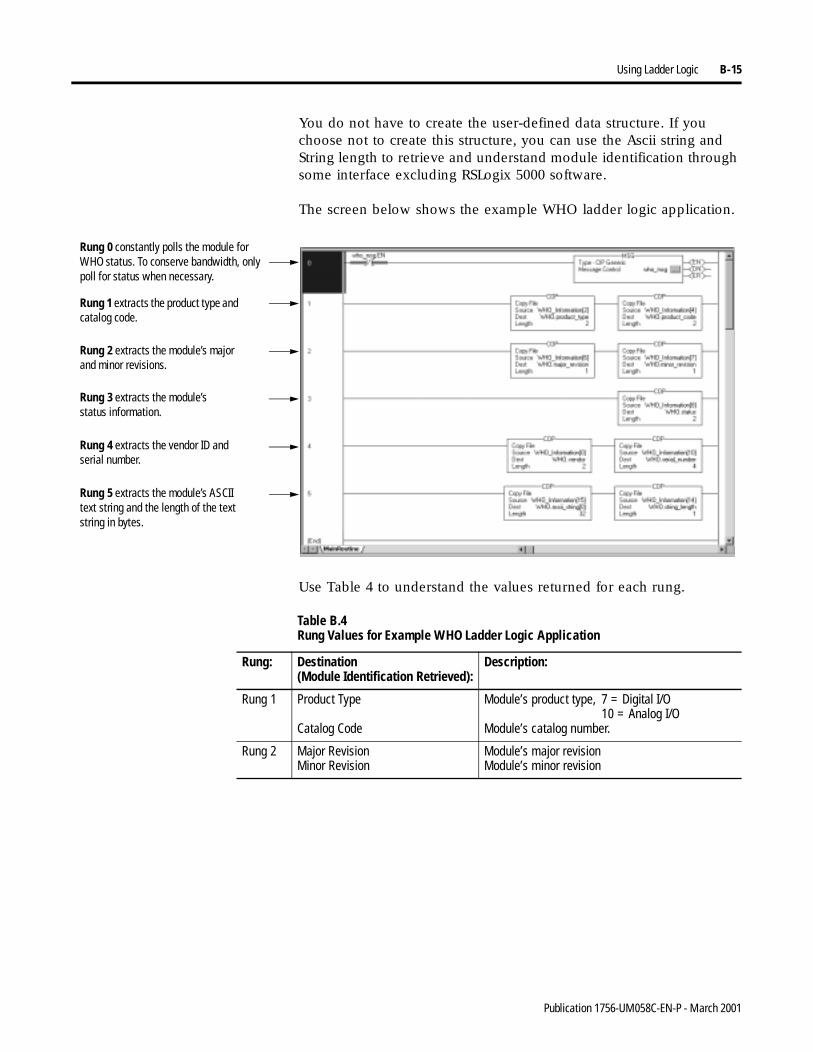
Using Ladder Logic B-15
You do not have to create the user-defined data structure. If you choose not to create this structure, you can use the Ascii string and String length to retrieve and understand module identification through some interface excluding RSLogix 5000 software.
The screen below shows the example WHO ladder logic application.
Use Table 4 to understand the values returned for each rung.
Rung 0 constantly polls the module for WHO status. To conserve bandwidth, only poll for status when necessary.
Rung 1 extracts the product type and catalog code.
Rung 2 extracts the module’s major and minor revisions.
Rung 3 extracts the module’s status information.
Rung 4 extracts the vendor ID and serial number.
Rung 5 extracts the module’s ASCII text string and the length of the text string in bytes.
Table B.4 Rung Values for Example WHO Ladder Logic Application
Rung: Destination(Module Identification Retrieved):
Description:
Rung 1 Product Type
Catalog Code
Module’s product type, 7 = Digital I/O10 = Analog I/O
Module’s catalog number.
Rung 2 Major RevisionMinor Revision
Module’s major revisionModule’s minor revision
Publication 1756-UM058C-EN-P - March 2001
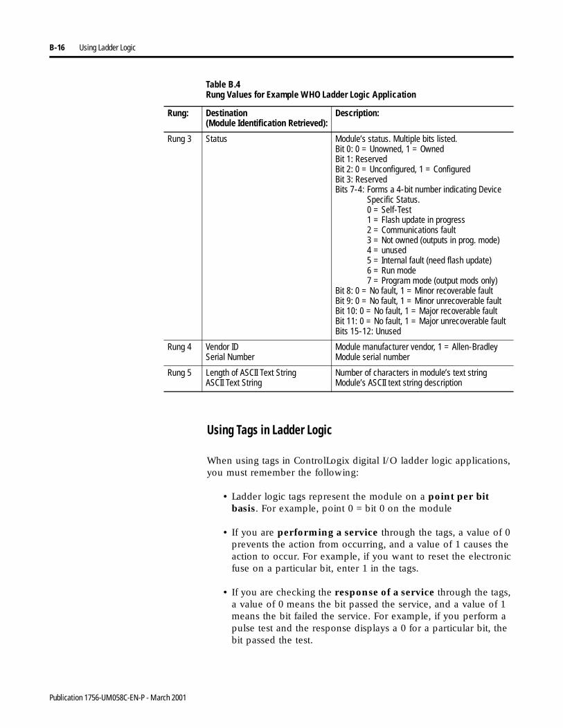
B-16 Using Ladder Logic
Using Tags in Ladder Logic
When using tags in ControlLogix digital I/O ladder logic applications, you must remember the following:
• Ladder logic tags represent the module on a point per bit basis. For example, point 0 = bit 0 on the module
• If you are performing a service through the tags, a value of 0 prevents the action from occurring, and a value of 1 causes the action to occur. For example, if you want to reset the electronic fuse on a particular bit, enter 1 in the tags.
• If you are checking the response of a service through the tags, a value of 0 means the bit passed the service, and a value of 1 means the bit failed the service. For example, if you perform a pulse test and the response displays a 0 for a particular bit, the bit passed the test.
Rung 3 Status Module’s status. Multiple bits listed.Bit 0: 0 = Unowned, 1 = OwnedBit 1: ReservedBit 2: 0 = Unconfigured, 1 = ConfiguredBit 3: ReservedBits 7-4: Forms a 4-bit number indicating Device
Specific Status.0 = Self-Test1 = Flash update in progress2 = Communications fault3 = Not owned (outputs in prog. mode)4 = unused5 = Internal fault (need flash update)6 = Run mode7 = Program mode (output mods only)
Bit 8: 0 = No fault, 1 = Minor recoverable faultBit 9: 0 = No fault, 1 = Minor unrecoverable faultBit 10: 0 = No fault, 1 = Major recoverable faultBit 11: 0 = No fault, 1 = Major unrecoverable faultBits 15-12: Unused
Rung 4 Vendor IDSerial Number
Module manufacturer vendor, 1 = Allen-BradleyModule serial number
Rung 5 Length of ASCII Text StringASCII Text String
Number of characters in module’s text stringModule’s ASCII text string description
Table B.4 Rung Values for Example WHO Ladder Logic Application
Rung: Destination(Module Identification Retrieved):
Description:
Publication 1756-UM058C-EN-P - March 2001
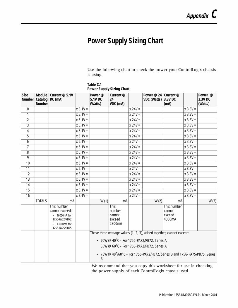
Appendix C
Power Supply Sizing Chart
Use the following chart to check the power your ControlLogix chassis is using.
We recommend that you copy this worksheet for use in checking the power supply of each ControlLogix chassis used.
Table C.1 Power Supply Sizing Chart
Slot Number
Module Catalog Number
Current @ 5.1V DC (mA)
Power @ 5.1V DC (Watts)
Current @ 24VDC (mA)
Power @ 24VDC (Watts)
Current @ 3.3V DC (mA)
Power @ 3.3V DC (Watts)
0 x 5.1V = x 24V = x 3.3V =1 x 5.1V = x 24V = x 3.3V =2 x 5.1V = x 24V = x 3.3V =3 x 5.1V = x 24V = x 3.3V =4 x 5.1V = x 24V = x 3.3V =5 x 5.1V = x 24V = x 3.3V =6 x 5.1V = x 24V = x 3.3V =7 x 5.1V = x 24V = x 3.3V =8 x 5.1V = x 24V = x 3.3V =9 x 5.1V = x 24V = x 3.3V =
10 x 5.1V = x 24V = x 3.3V =11 x 5.1V = x 24V = x 3.3V =12 x 5.1V = x 24V = x 3.3V =13 x 5.1V = x 24V = x 3.3V =14 x 5.1V = x 24V = x 3.3V =15 x 5.1V = x 24V = x 3.3V =16 x 5.1V = x 24V = x 3.3V =
TOTALS mA W (1) mA W (2) mA W (3)This number cannot exceed:
• 10000mA for 1756-PA72/PB72
• 13000mA for 1756-PA75/PB75
This number cannot exceed 2800mA
This number cannot exceed 4000mA
These three wattage values (1, 2, 3), added together, cannot exceed:
• 70W @ 40oC - For 1756-PA72/PB72, Series A
55W @ 60oC - For 1756-PA72/PB72, Series A
• 75W @ 40o/60°C - For 1756-PA72/PB72, Series B and 1756-PA75/PB75, Series A
1 Publication 1756-UM058C-EN-P - March 2001

C-2 Power Supply Sizing Chart
Notes:
Publication 1756-UM058C-EN-P - March 2001
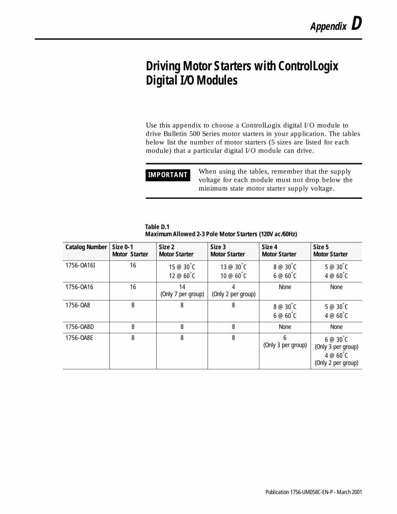
Appendix D
Driving Motor Starters with ControlLogix Digital I/O Modules
Use this appendix to choose a ControlLogix digital I/O module to drive Bulletin 500 Series motor starters in your application. The tables below list the number of motor starters (5 sizes are listed for each module) that a particular digital I/O module can drive.
IMPORTANT When using the tables, remember that the supply voltage for each module must not drop below the minimum state motor starter supply voltage.
Table D.1 Maximum Allowed 2-3 Pole Motor Starters (120V ac/60Hz)
Catalog Number Size 0-1 Motor Starter
Size 2 Motor Starter
Size 3Motor Starter
Size 4Motor Starter
Size 5Motor Starter
1756-OA16I 16 15 @ 30°C12 @ 60°C
13 @ 30°C10 @ 60°C
8 @ 30°C6 @ 60°C
5 @ 30°C4 @ 60°C
1756-OA16 16 14(Only 7 per group)
4(Only 2 per group)
None None
1756-OA8 8 8 8 8 @ 30°C6 @ 60°C
5 @ 30°C4 @ 60°C
1756-OA8D 8 8 8 None None
1756-OA8E 8 8 8 6 (Only 3 per group)
6 @ 30°C(Only 3 per group)
4 @ 60°C(Only 2 per group)
1 Publication 1756-UM058C-EN-P - March 2001
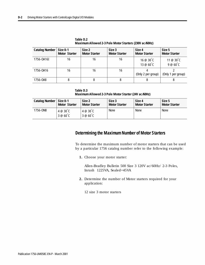
D-2 Driving Motor Starters with ControlLogix Digital I/O Modules
Determining the Maximum Number of Motor Starters
To determine the maximum number of motor starters that can be used by a particular 1756 catalog number refer to the following example:
1. Choose your motor starter:
Allen-Bradley Bulletin 500 Size 3 120V ac/60Hz/ 2-3 Poles, Inrush 1225VA, Sealed=45VA
2. Determine the number of Motor starters required for your application:
12 size 3 motor starters
Table D.2 Maximum Allowed 2-3 Pole Motor Starters (230V ac/60Hz)
Catalog Number Size 0-1 Motor Starter
Size 2 Motor Starter
Size 3Motor Starter
Size 4Motor Starter
Size 5Motor Starter
1756-OA16I 16 16 16 16 @ 30°C13 @ 60°C
11 @ 30°C9 @ 60°C
1756-OA16 16 16 16 4(Only 2 per group)
2(Only 1 per group)
1756-OA8 8 8 8 8 8
Table D.3 Maximum Allowed 2-3 Pole Motor Starter (24V ac/60Hz)
Catalog Number Size 0-1 Motor Starter
Size 2 Motor Starter
Size 3Motor Starter
Size 4Motor Starter
Size 5Motor Starter
1756-ON8 4 @ 30°C3 @ 60°C
4 @ 30°C3 @ 60°C
None None None
Publication 1756-UM058C-EN-P - March 2001
Driving Motor Starters with ControlLogix Digital I/O Modules D-3
3. Choose a ControlLogix digital output module:
1756-OA16I/AOutput voltage = 74 – 265V ac
Output steady state current per point = 2A maximum @ 30°C
& 1A maximum @ 60°C (Linear derating)Output steady state current per module = 5A maximum @
30°C
& 4A maximum @ 60°C (Linear derating)Output surge current per point = 20A maximum for
43mS repeatable every 2S @ 60°C
4. Determine the maximum environmental operating temperature:
50°C
5. Confirm the voltage Range is within the Motor starter range:
Motor Starter uses 120V ac1756-OA16I/A operates in a 74 – 120V ac voltage range
6. Confirm the inrush current per point:
Inrush of motor starter – Line voltage = Inrush current = 1225VA/120V ac = 10.2Amps Inrush
The 1756-OA16I allows 20A Inrush current from above
specification at @ 60°C
7. Confirm the steady state point current of the module can drive the motor starter:
Sealed/Line voltage = Steady state current = 45VA/120V ac
= 0.375A @ 50°C
Output point current can drive: 2A - (.033ma X 10°C)
= 2A - 0.33A = 1.67A @ 50°C
Above 30°C, output point derates to .033mA/°C (point derating)
The 1756-OA16I/A output point current (1.67A) can drive the
motor starter (0.375A) @ 50°C
Publication 1756-UM058C-EN-P - March 2001
D-4 Driving Motor Starters with ControlLogix Digital I/O Modules
8. Confirm the 1756-OA16I/A total module current can drive 12
size 3 motor starters @ 50°C:
Motor starter steady state current X 11 motor starters = .375 X 12
= 4.5A @ 50°C
The output total module current can drive: 5A - (.033ma X
10°C) = 5A - 0.33A = 4.67A @ 50°C
Above 30°C total output current derates to .033mA/°C (Module derating)
The 1756-OA16I/A total output current (4.67A) can drive
the 12 motor starters (4.5A) @ 50°C
Publication 1756-UM058C-EN-P - March 2001
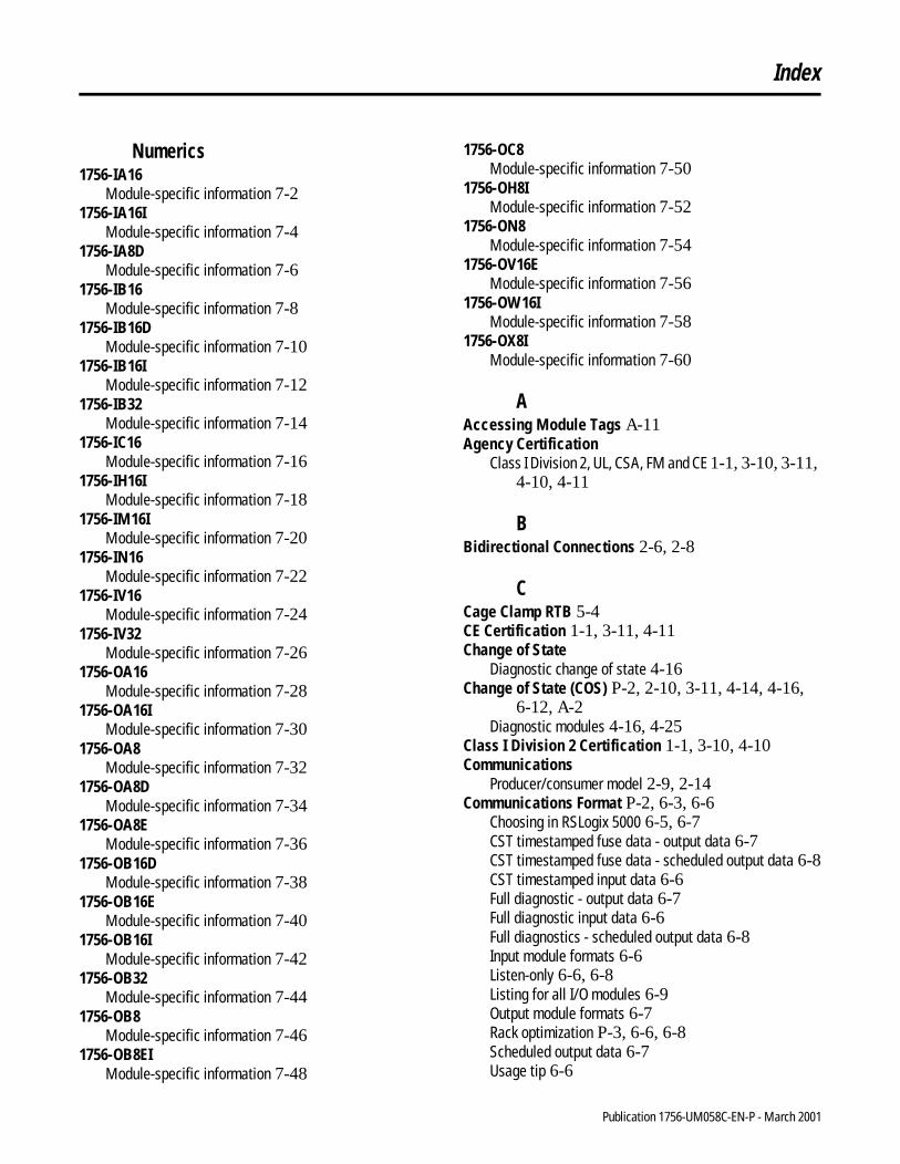
Index
Numerics1756-IA16
Module-specific information 7-21756-IA16I
Module-specific information 7-41756-IA8D
Module-specific information 7-61756-IB16
Module-specific information 7-81756-IB16D
Module-specific information 7-101756-IB16I
Module-specific information 7-121756-IB32
Module-specific information 7-141756-IC16
Module-specific information 7-161756-IH16I
Module-specific information 7-181756-IM16I
Module-specific information 7-201756-IN16
Module-specific information 7-221756-IV16
Module-specific information 7-241756-IV32
Module-specific information 7-261756-OA16
Module-specific information 7-281756-OA16I
Module-specific information 7-301756-OA8
Module-specific information 7-321756-OA8D
Module-specific information 7-341756-OA8E
Module-specific information 7-361756-OB16D
Module-specific information 7-381756-OB16E
Module-specific information 7-401756-OB16I
Module-specific information 7-421756-OB32
Module-specific information 7-441756-OB8
Module-specific information 7-461756-OB8EI
Module-specific information 7-48
1756-OC8Module-specific information 7-50
1756-OH8IModule-specific information 7-52
1756-ON8Module-specific information 7-54
1756-OV16EModule-specific information 7-56
1756-OW16IModule-specific information 7-58
1756-OX8IModule-specific information 7-60
AAccessing Module Tags A-11Agency Certification
Class I Division 2, UL, CSA, FM and CE 1-1, 3-10, 3-11, 4-10, 4-11
BBidirectional Connections 2-6, 2-8
CCage Clamp RTB 5-4CE Certification 1-1, 3-11, 4-11Change of State
Diagnostic change of state 4-16Change of State (COS) P-2, 2-10, 3-11, 4-14, 4-16,
6-12, A-2Diagnostic modules 4-16, 4-25
Class I Division 2 Certification 1-1, 3-10, 4-10Communications
Producer/consumer model 2-9, 2-14Communications Format P-2, 6-3, 6-6
Choosing in RSLogix 5000 6-5, 6-7CST timestamped fuse data - output data 6-7CST timestamped fuse data - scheduled output data 6-8CST timestamped input data 6-6Full diagnostic - output data 6-7Full diagnostic input data 6-6Full diagnostics - scheduled output data 6-8Input module formats 6-6Listen-only 6-6, 6-8Listing for all I/O modules 6-9Output module formats 6-7Rack optimization P-3, 6-6, 6-8Scheduled output data 6-7Usage tip 6-6
Publication 1756-UM058C-EN-P - March 2001
Index 2
Compatible MatchElectronic keying 3-5, 4-5
ConfigurationAccessing module tags 6-23, A-11Altering the default configuration 6-10Changing through module tags A-12Configuring a diagnostic input module 6-14Configuring a diagnostic output module 6-15Configuring a nondiagnostic input module 6-12Configuring a nondiagnostic output module 6-13Configuring modules in remote chassis 6-19Creating a new module 6-4Downloading new data A-14Downloading new data from the tag editor A-14Dynamic reconfiguration 6-16Editing configuration in RSLogix 5000 6-16Local vs. remote chassis 6-2Message configuration with ladder logic B-4Overview of the process 6-2Reconfiguring in program mode 6-18Reconfiguring in remote run mode 6-17Using module tags A-3, A-4, A-6, A-8Using RSLogix 5000 6-2Using the default configuration 6-10
Configuring a ControlLogix SystemUsing RSLogix 5000 2-2Using RSNetWorx 2-2
Connections P-2, 2-6Connector pins on the module 1-4ControlBus P-2, 1-4Differences between direct and rack connections 2-9Direct connection P-2, 2-6Listen-only connection P-2Listen-only rack optimization 2-7Number allowed 2-6, 2-7, 2-8Rack connection 2-7Rack optimization 2-7, 2-8, 6-6
ControlBus Connector P-2, 1-4Controller
Logix5550 Controller P-1, 2-2ControlNet
Direct connections 2-6Input modules in remote chassis 2-11Network Update Time (NUT) P-3Output modules in remote chassis 2-15Rack connection P-3, 2-7Rack optimization P-3, 2-7Tip on conserving bandwidth 2-11
Coordinated System Time (CST) P-2CSA Certification 1-1, 3-11, 4-11CST Timestamped Fuse Data - Output Data
Communications Format 6-7CST Timestamped Fuse Data - Scheduled Output Data
Communications Format 6-8CST Timestamped Input Data Communications Format
6-6
DData Exchange
Producer/consumer model 1-1, 2-9, 2-14, 3-9, 4-9Data Transmissions
Adjusting the RPI 6-18Choosing an input module communications format 6-6Choosing an output module communications format 6-7COS 2-10, 3-11, 4-14, 4-16Diagnostic change of state 4-16Diagnostic output modules 4-25RPI P-3, 2-10, 3-11, 4-14, 4-16, 4-25Using COS on nondiagnostic input modules 6-12Using timestamped inputs and scheduled outputs B-10
Default Configuration 6-10Diagnostic Change of State 4-16, 4-25Diagnostic Latching 3-17, 4-11Diagnostic Timestamp 4-11Direct Connection P-2, 2-6Disable Keying
Electronic keying 3-6, 4-6Downloading Configuration Data
From the tag editor A-14Dynamic Reconfiguration 6-16
EElectronic Keying P-2, 3-4, 4-4, 6-9
Choosing in RSLogix 5000 6-5, 6-9Compatible match P-2, 3-5, 4-5Disable keying P-2, 3-6, 4-6Exact match P-2, 3-4, 4-4Usage tip 3-5, 4-5
Electrostatic DischargePreventing 1-6
Exact MatchElectronic keying 3-4, 4-4
Extended-Depth HousingCabinet-size considerations 5-9Using 5-8, 5-9
Publication 1756-UM058C-EN-P - March 2001
Index 3
FFault Reporting
Determining fault type with RSLogix 5000 8-5Diagnostic input modules 4-25Diagnostic modules 4-3, 4-12Diagnostic output modules 4-17, 4-27Standard input modules 3-18Standard modules 3-3Standard output modules 3-19
Field Power Loss Detection1756-IA8D module 4-161756-OA8E module 3-17
Field Power Loss WordDiagnostic input modules 4-25, 4-26Diagnostic output modules 4-27, 4-28Standard output modules 3-19, 3-20
Filter TimesSoftware configurable 3-11, 4-14
FM Certification 1-1, 3-11, 4-11Full Diagnostic - Output Data Communications Format
6-7Full Diagnostic Input Data Communications Format 6-6Full Diagnostics - Scheduled Output Data
Communications Format 6-8Fuse Blown Word
Diagnostic output modules 4-27, 4-28Standard output modules 3-19, 3-20
FusingDiagnostic output modules 4-20, 4-24Nondiagnostic output modules 3-14Recommended fuses for diagnostic output modules 4-20Recommended fuses for standard output modules 3-15Resetting a fuse in ladder logic B-13Resetting electronic fuse in RSLogix 5000 6-22
HHousing
Choosing the extended-depth housing 5-8
IInhibit
Choosing in RSLogix 5000 6-10Preventing communication P-2
Input Module FiltersConfiguring in RSLogix 5000 3-11, 4-14, 6-12, 6-14
Input Online Services 6-21Installing the ControlLogix I/O Module 5-1Interface Module (IFM) P-2, 1-2Internal Module Operations 2-4
JJumper Bar 5-5
Using with 1756-IA16I module 7-4Using with the 1756-IB16I module 7-12Using with the 1756-IH16I module 7-18Using with the 1756-IM16I module 7-20Using with the 1756-OA16I module 7-30Using with the 1756-OB16I module 7-42Using with the 1756-OW16I module 7-58Using with the 1756-OX8I module 7-60
KKeying 5-2
Electronic 3-4, 4-4Mechanical keying 1-4
LLadder Logic
Creating new tag B-3Message configuration B-4message instruction B-3Message instructions B-1Message number of elements B-6Message object attributes B-6Message object ID B-6Message object types B-6Message service codes B-6Module services B-2Performing the pulse test B-13Resetting a fuse B-13Resetting latched diagnostics B-13
Latched Diagnosticsresetting with ladder logic B-13
LatchingDiagnostic latching 3-17, 4-11
Leakage ResistorDetermining on 1756-IA8D module 7-6Determining on 1756-IB16D module 7-10
LED Status Indicators 3-10, 4-10Input modules 8-1Output modules 8-2
Listen-Only Communications FormatsInput modules 6-6Output modules 6-8
Listen-Only Connections P-2, 2-17Listen-Only Rack Connection 2-7Listen-Only Rack Optimization 2-7
Publication 1756-UM058C-EN-P - March 2001
Index 4
Local ChassisGeneral I/O module operation 2-2Using input modules 2-10Using output modules 2-14
Locking Tab 1-4Logix5550 Controller P-1, 2-2
Bidirectional connections 2-6, 2-8Loss of Field Power 3-13, 4-18Loss of Field Power Detection
Diagnostic output modules 4-24
MMajor Revision P-3, 3-4, 4-4, 6-3
Choosing in RSLogix 5000 6-5Considerations for timestamping 3-9, 4-9
Marking Diagnostic Data Changes 4-11Mechanical Keying 1-4Message Instructions
In ladder logic B-1Minor Revision P-3, 3-4, 4-4, 6-3
Choosing in RSLogix 5000 6-5Module Compatibility
Diagnostic input modules 4-1Diagnostic output modules 4-2Nondiagnostic input modules 3-1Nondiagnostic output modules 3-2
Module Fault WordDiagnostic input modules 4-25, 4-26Diagnostic output modules 4-27, 4-28Standard input modules 3-18Standard output modules 3-19, 3-20
Module Identification Information 1-5, B-14ASCII text string 1-5Catalog code 1-5Major revision 1-5Minor revision 1-5Product type 1-5Retrieving 3-3, 4-3Serial number 1-5Status 1-5Vendor ID 1-5WHO service 1-5
Module ServicesIn ladder logic B-2
Module StatusRetrieving 1-5, B-14
Module TagsAccessing in RSLogix 5000 6-23, A-11
Changing configuration A-12Diagnostic input modules A-6Diagnostic output modules A-8Sample series (input module) A-15Sample series (output module) A-16Standard input modules A-3Standard output modules A-4
Module-Specific Information1756-IA16 7-21756-IA16I 7-41756-IA8D 7-61756-IB16 7-81756-IB16D 7-101756-IB16I 7-121756-IB32 7-141756-IC16 7-161756-IH16I 7-181756-IM16I 7-201756-IN16 7-221756-IV16 7-241756-IV32 7-261756-OA16 7-281756-OA16I 7-301756-OA8 7-321756-OA8D 7-341756-OA8E 7-361756-OB16D 7-381756-OB16E 7-401756-OB16I 7-421756-OB32 7-441756-OB8 7-461756-OB8EI 7-481756-OC8 7-501756-OH8I 7-521756-ON8 7-541756-OV16E 7-561756-OW16I 7-581756-OX8I 7-60
Multiple OwnersOf input modules 2-18
NNEMA Clamp RTB 5-4Network Update Time (NUT) P-3No Load Detection
Diagnostic output modules 4-21No Load Word
Diagnostic output modules 4-27, 4-28
Publication 1756-UM058C-EN-P - March 2001
Index 5
OOnline Services
Input modules 6-21Output modules 6-22
Open Wire Detection 4-15Open Wire Word
Diagnostic input modules 4-25, 4-26Output Data Echo 2-14, 2-17, 3-13, 4-18Output Fault State
Configuable in RSLogix 5000 3-12Output Fault States
Configuring in RSLogix 5000 4-17Output Online Services 6-22Output Verification
Diagnostic output modules 4-22Output Verify Word
Diagnostic output modules 4-27, 4-28Owner Controller
Logix5550 Controller P-1, 2-2Ownership 2-2
Direct connections 2-6Listen-only 2-17Listen-only rack optimization 2-7Multiple owners P-3Multiple owners of input modules 2-18Owner controller P-3Owner-controller-I/O module relationship 2-2Rack connection P-3, 2-7Rack optimization 2-7, 2-8Remote connections P-3, 2-11, 2-15
PPoint Level Fault Reporting
Diagnostic modules 4-12Preventing Electrostatic Discharge 1-6Producer/Consumer
Communications 1-1Network model 1-1, 2-9, 2-14, 3-9, 4-9
Product IdentificationCatalog number 3-4, 4-4Major revision P-3, 3-4, 4-4Minor revision P-3, 3-4, 4-4Product type 3-4, 4-4Vendor 3-4, 4-4
Program Mode P-3Reconfiguring the module 6-18
Pulse TestDiagnostic output modules 4-22Performing with ladder logic B-13Usage tips 4-22
RRack Connection 2-7, 2-8
Usage recommendations 2-8Rack Connections P-3, 2-7Rack Optimization P-3, 2-7, 2-8, 6-6Rack Optimization Communications Format 6-8Remote Chassis
Configuring remote I/O modules 6-19General I/O module operation 2-3Using input modules 2-11
Scenarios for data transfer 2-13Using output modules 2-15
Scenarios for data transfer 2-16Remote Connections P-3Remote Run Mode
Reconfiguring the module 6-17Removable Terminal Block (RTB) P-3, 1-2, 1-4, 5-2
Installing 5-10Mechanically keying the RTB 5-2Removing 5-12Using with the housing 5-7Wiring the RTB 5-4
Removal and Insertion Under Power (RIUP) P-3, 1-1, 1-6, 3-3, 4-3, 5-1
Requested Packet Interval (RPI) P-3, 2-10, 3-11, 4-14, 4-16, 4-25
Adjusting in RSLogix 5000 6-10, 6-18Retrieving Module Identification Information 1-5, B-14Retrieving Module Status 1-5, B-14RSLogix 5000
Configuring I/O modules 2-2, 3-3, 4-3, 6-2Filter times 3-11, 4-14I/O modules in remote chassis 2-3Using software configuration tags A-1Using to troubleshoot 8-4Using with RSNetWorx 2-2
RSNetWorxI/O modules in remote chassis 2-3Transferring data to networked I/O modules and
establishing a NUT 2-2Using with RSLogix 5000 2-2
Publication 1756-UM058C-EN-P - March 2001
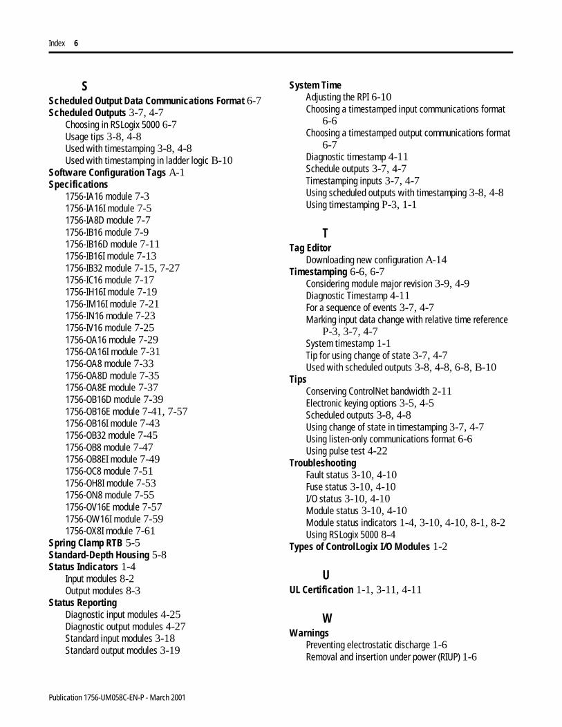
Index 6
SScheduled Output Data Communications Format 6-7Scheduled Outputs 3-7, 4-7
Choosing in RSLogix 5000 6-7Usage tips 3-8, 4-8Used with timestamping 3-8, 4-8Used with timestamping in ladder logic B-10
Software Configuration Tags A-1Specifications
1756-IA16 module 7-31756-IA16I module 7-51756-IA8D module 7-71756-IB16 module 7-91756-IB16D module 7-111756-IB16I module 7-131756-IB32 module 7-15, 7-271756-IC16 module 7-171756-IH16I module 7-191756-IM16I module 7-211756-IN16 module 7-231756-IV16 module 7-251756-OA16 module 7-291756-OA16I module 7-311756-OA8 module 7-331756-OA8D module 7-351756-OA8E module 7-371756-OB16D module 7-391756-OB16E module 7-41, 7-571756-OB16I module 7-431756-OB32 module 7-451756-OB8 module 7-471756-OB8EI module 7-491756-OC8 module 7-511756-OH8I module 7-531756-ON8 module 7-551756-OV16E module 7-571756-OW16I module 7-591756-OX8I module 7-61
Spring Clamp RTB 5-5Standard-Depth Housing 5-8Status Indicators 1-4
Input modules 8-2Output modules 8-3
Status ReportingDiagnostic input modules 4-25Diagnostic output modules 4-27Standard input modules 3-18Standard output modules 3-19
System TimeAdjusting the RPI 6-10Choosing a timestamped input communications format
6-6Choosing a timestamped output communications format
6-7Diagnostic timestamp 4-11Schedule outputs 3-7, 4-7Timestamping inputs 3-7, 4-7Using scheduled outputs with timestamping 3-8, 4-8Using timestamping P-3, 1-1
TTag Editor
Downloading new configuration A-14Timestamping 6-6, 6-7
Considering module major revision 3-9, 4-9Diagnostic Timestamp 4-11For a sequence of events 3-7, 4-7Marking input data change with relative time reference
P-3, 3-7, 4-7System timestamp 1-1Tip for using change of state 3-7, 4-7Used with scheduled outputs 3-8, 4-8, 6-8, B-10
TipsConserving ControlNet bandwidth 2-11Electronic keying options 3-5, 4-5Scheduled outputs 3-8, 4-8Using change of state in timestamping 3-7, 4-7Using listen-only communications format 6-6Using pulse test 4-22
TroubleshootingFault status 3-10, 4-10Fuse status 3-10, 4-10I/O status 3-10, 4-10Module status 3-10, 4-10Module status indicators 1-4, 3-10, 4-10, 8-1, 8-2Using RSLogix 5000 8-4
Types of ControlLogix I/O Modules 1-2
UUL Certification 1-1, 3-11, 4-11
WWarnings
Preventing electrostatic discharge 1-6Removal and insertion under power (RIUP) 1-6
Publication 1756-UM058C-EN-P - March 2001
Index 7
Wiring ConnectionsChoosing the extended-depth housing 5-8Field wiring options 3-14, 4-19Isolated and non-isolated modules 3-12, 4-14Recommendations for wiring RTB 5-5Using the cage clamp RTB 5-4Using the interface module (IFM) P-2, 1-2Using the NEMA clamp RTB 5-4Using the removable terminal block (RTB) P-3, 1-2, 5-2,
5-4Using the spring clamp RTB 5-4
Wiring Example1756-IA16 module 7-21756-IA16I module 7-4, 7-301756-IA8D module 7-61756-IB16 module 7-8, 7-241756-IB16D module 7-101756-IB16I module 7-121756-IB32 module 7-14, 7-261756-IC16 module 7-161756-IH16I module 7-18
1756-IM16I module 7-201756-IN16 module 7-221756-IV16 module 7-241756-OA16 module 7-281756-OA16I module 7-301756-OA8 module 7-321756-OA8D module 7-341756-OA8E module 7-361756-OB16D module 7-381756-OB16E module 7-40, 7-561756-OB16I module 7-421756-OB32 module 7-441756-OB8 module 7-461756-OB8EI module 7-481756-OC8 module 7-501756-OH8I module 7-521756-ON8 module 7-541756-OV16E module 7-561756-OW16I module 7-581756-OX8I module 7-60
Publication 1756-UM058C-EN-P - March 2001

Index 8
Notes:
Publication 1756-UM058C-EN-P - March 2001
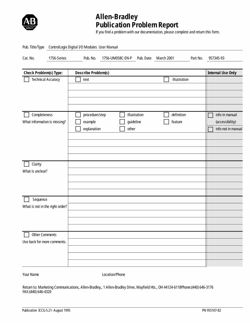
Allen-BradleyPublication Problem ReportIf you find a problem with our documentation, please complete and return this form.
Pub. Title/Type ControlLogix Digital I/O Modules User Manual
Cat. No. 1756-Series Pub. No. 1756-UM058C-EN-P Pub. Date March 2001 Part No. 957345-93
Check Problem(s) Type: Describe Problem(s) Internal Use Only
Technical Accuracy text illustration
Completeness procedure/step illustration definition info in manual
What information is missing? example guideline feature (accessibility)
explanation other info not in manual
Clarity
What is unclear?
Sequence
What is not in the right order?
Other Comments
Use back for more comments.
Your Name Location/Phone
Return to: Marketing Communications, Allen-Bradley., 1 Allen-Bradley Drive, Mayfield Hts., OH 44124-6118Phone:(440) 646-3176FAX:(440) 646-4320
Publication ICCG-5.21- August 1995 PN 955107-82
Other Comments
PLEASE FOLD HERE
NO POSTAGE NECESSARY IF MAILED
IN THE UNITED STATES
BUSINESS REPLY MAILFIRST-CLASS MAIL PERMIT NO. 18235 CLEVELAND OH
POSTAGE WILL BE PAID BY THE ADDRESSEE
1 ALLEN-BRADLEY DRMAYFIELD HEIGHTS OH 44124-9705
PLEASE FASTEN HERE (DO NOT STAPLE)
PLEA
SE R
EMOV
E

3
1756-UM058C-EN-P - March

Publication 1756-UM058C-EN-P - March 2001 1 PN 957345-93Supersedes Publication 1756-6.5.8 - July 1999 © 2001 Rockwell International Corporation. Printed in the U.S.A.