controlling wild bodies using linear temporal logic · controlling wild bodies using linear...
TRANSCRIPT

Robotics: Science and Systems 2011Los Angeles, CA, USA, June 27-30, 2011
1
Controlling Wild BodiesUsing Linear Temporal Logic
Leonardo Bobadilla Oscar Sanchez Justin [email protected] [email protected] [email protected]
Katrina Gossman Steven M. [email protected] [email protected]
Department of Computer ScienceUniversity of Illinois
Urbana, IL 61801 USA
(a) (b)
Fig. 1. a) Our vehicle of study is a $4 weasel ball; b) it consists entirely ofa battery and slowly oscillating motor mounted to a plastic shell.
Abstract—There is substantial interest controlling a group ofbodies from specifications of tasks given in a high-level, human-like language. This paper proposes a methodology that createslow-level hybrid controllers that guarantee that a group of bodiesexecute a high-level specified task without dynamical systemmodeling, precise state estimation or state feedback. We dothis by exploiting the wild motions of very simple bodies in anenvironment connected by gates which serve as the system inputs,as opposed motors on the bodies. We present experiments usinginexpensive hardware demonstrating the practical feasibility ofour approach to solving tasks such as navigation, patrolling, andcoverage.
I. I NTRODUCTION
A fundamental challenge in robotics is the construction ofrobot control strategies from specifications of tasks givenin ahigh-level language. Ideally, we would like to describe taskssuch as navigation, patrolling, coverage, and herding, andhavethem autonomously executed by a team of robots [2]. Thelow level details of the plan should be hidden. Furthermore,new plans must be efficiently constructed and guaranteed tobe correct.
We propose an unusual paradigm as a thought-provokingstep toward meeting this challenge. A common approach tomany problems is to carefully design an autonomous vehicle,which involves steps such as system modeling and identifica-tion, implementing stable controllers, and installing sufficientsensing to ensure state feedback. In contrast, we propose tostart with a “wildly behaving” body for which its precise
equations of motion are unknown, it is far from stable, and haslittle or no sensing capabilities. Our main “vehicle” of studywill be a $4 weasel ball (see Figure 1, which has no sensors,no computation, and one motor, which oscillates constantlyatabout2Hz.
Although used throughout the experiments in this paper,the particular choice of body is not critical. We instead careonly about its high-level motion properties. We informallyconsider a body to bewild if when placed into a boundedregion r ⊂ R
2, it moves along a trajectory that strikes everyopen interval along the boundary ofr infinitely often. Bystrike, we mean that the body contacts the boundary witha non-tangential velocity. A well-studied family of systemsthat have this property is calleddynamical billiards [35](imagine a billiard ball that bounces off of the table sidesforever). A strong system property that arises in that workand achieves our required wild behavior isergodicity.1 Theidea of exploiting wild motions in robotics is reminiscent ofthe randomization work by Erdmann [11] and designing robotsystems with ergodic dynamics by Shell et al. [33].
How do we control such systems? We are first inspired bythe power of abstraction used in hybrid systems [6], [16], [18].Following this, we are inspired by the family of work thatconverts high-level specifications into low-level controllawsfor the hybrid system [21], [30], [36]. In particular, our workuses the Linear Temporal Logic (LTL) framework that hasbeen developed in several recent works [3], [13], [14], [17],[22], [23], [24], [25], [26], [27], [28], [34], [37].
Although we borrow the overall LTL framework, ourmethod of control substantially differs. Whereas it is commonin LTL implementations to derive state-feedback control lawswithin continuous regions [17], [22], [28], [34], we simplylet our “vehicle” behave wildly. To control a wild body,we designgates that appear only along region boundariesand connect to other regions. When a body strikes a gate,the gate will induce our planned behavior, which might beto remain in the region or transition to another region. In
1In this context, ergodicity does not necessarily have anything to do withprobabilities, as in the more commonly seen case of Markov chains.
this sense, we “gently guide” the body. This differs fromprevious LTL implementations because we do not requiresystem identification, state feedback, or a state-feedbackcon-trol law. Our approach instead draws inspiration from severalareas, includingnonprehensile manipulation[12], [19], [31]and vibrating plates [5], [32]. Even more closely related aredesigning virtual fences to control herds of cows [7] anddesigning fire evacuation strategies to safely “herd” humansout of a burning building [8].
Our approach consists of four steps. First, we proposediscrete abstractions for the motion of one or more wildbodies. Second, we use a temporal logic to give descriptionsof tasks. Third, we translate the temporal logic specificationinto a discrete plan. Finally, this discrete plan is converted intoa policy that is executed in our setup involving simple gatesand bodies.
The paper is organized as follows. Section II presents somepreliminary concepts, including the interaction between thewild body, the gates, and the regions. Sections III and IVpresent our approach for the cases of a single and multiplebodies, respectively. Section V presents experiments and Sec-tion V concludes the paper.
II. T HE OVERALL DESIGN
Regions and gates
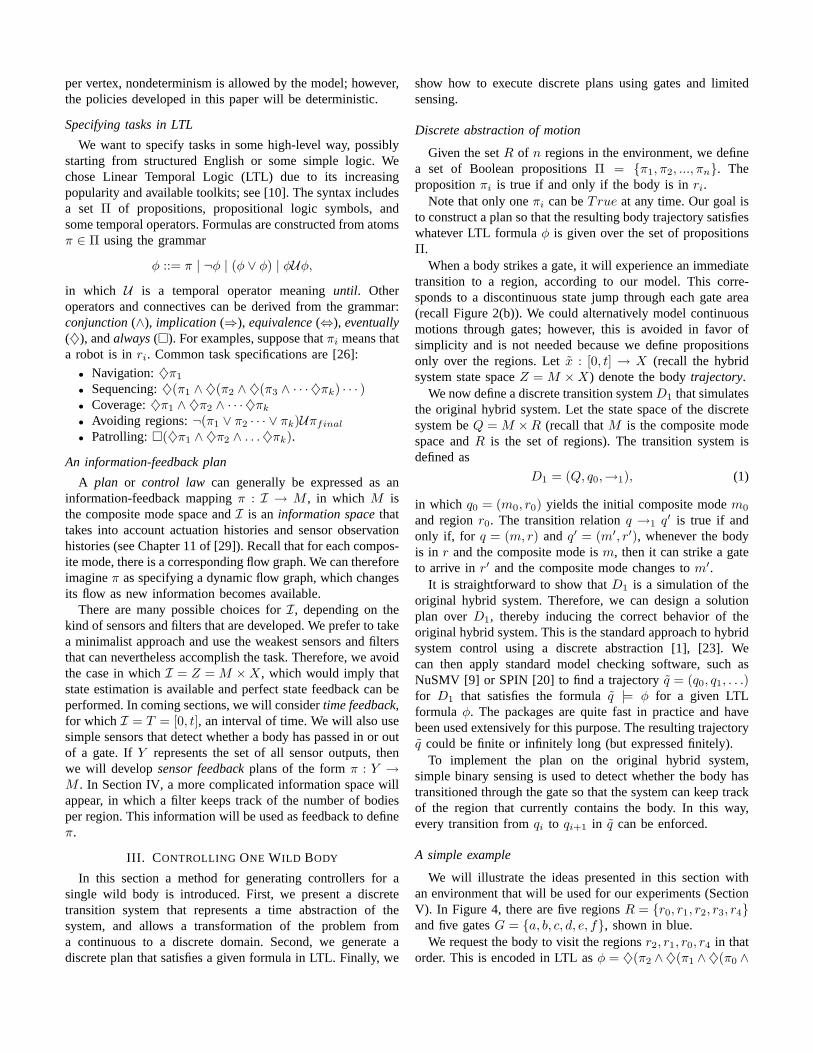
Consider a planar workspaceE ⊂ R2 that is partitioned
into an obstacle setO and a finite set of bounded cells withconnected open interior, each of which is either aregionor a gate; Figure 2 shows a simple example. The followingconditions are imposed: 1) No region shares a boundary withany other region, 2) No gate shares a boundary with any othergate; 3) Every region shares a boundary with at least one gate;4) If a gate and a region share a boundary, then the boundaryis a connected interval (rather than being a point or beingdisconnected). LetR denote the set of all regions andG denotethe set of all gates. The union of allr ∈ R, all g ∈ G, andO
yields E.
g4g1
r1
r2 r3
r5r4
O
O
g2
g3
Fig. 2. An example arrangement of five regions and four gates.
Wild bodies
We now place abody b into the workspace. The body isassumed to be “small” with respect to the sizes of regions,gates, and their shared boundaries. It is therefore modeled
r3g3r2
r1 g2 r4 r5
g1 g4
r3r2
r1 r4 r5
(a) (b)
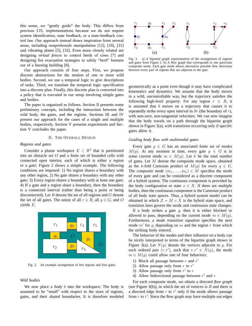
Fig. 3. a) A bipartite graph representation of the arrangement of regionsand gates from Figure 2. b) A flow graph that corresponds to oneparticularcomposite mode. Each gate mode allows alternative possible flowdirectionsbetween every pair of regions that are adjacent to the gate.
geometrically as a point even though it may have complicatedkinematics and dynamics. We assume that the body movesin a wild, uncontrollable way, but the trajectory satisfies thefollowing high-level property: For any regionr ∈ R, itis assumed thatb moves on a trajectory that causes it torepeatedly strike every open interval in∂r (the boundary ofr),with non-zero, non-tangential velocities. We can now imaginethat the body travels on a path through the bipartite graphshown in Figure 3(a), with transitions occurring only if specificgates allow it.
Guiding body flow with multimodal gates
Every gateg ∈ G has an associated finite set ofmodesM(g). At any moment in time, every gateg ∈ G is insome current modem ∈ M(g). Let k be the total numberof gates. LetM denote the composite mode space, obtainedas thek-fold Cartesian product ofM(g) for every g ∈ G.The composite mode(m1, . . . ,mk) ∈ M specifies the modeof every gate and can be considered as a discrete componentof a hybrid system. The continuous component is provided bythe body configuration or statex ∈ X. If there are multiplebodies, then the continuous component is the Cartesian productof all body state spaces. Thus, a hybrid system model can beobtained in whichZ = M ×X is the hybrid state space, andtransition laws govern the mode and continuous state changes.
If a body strikes a gateg, then it is either blocked orallowed to pass, depending on the current modem ∈ M(g).Furthermore, amode transition equationspecifies the nextmodem′ for g, depending onm and the regionr from whichthe striking body entered.
The behavior of the modes and their influence on a body canbe nicely interpreted in terms of the bipartite graph shown inFigure 3(a). LetN(g) denote the vertices adjacent tog. Foreach ordered pair(r, r′), such thatr, r′ ∈ N(g), the modem ∈ M(g) could allow one of four behaviors:
1) Block all passage betweenr andr′
2) Allow passage only fromr to r′
3) Allow passage only fromr′ to r
4) Allow bidirectional passage betweenr′ andr
For each composite mode, we obtain a directedflow graph(see Figure 3(b)), in which the set of vertices isR and there isa directed edge fromr to r′ only if the mode allows passagefrom r to r′. Since the flow graph may have multiple out edges
per vertex, nondeterminism is allowed by the model; however,the policies developed in this paper will be deterministic.
Specifying tasks in LTL
We want to specify tasks in some high-level way, possiblystarting from structured English or some simple logic. Wechose Linear Temporal Logic (LTL) due to its increasingpopularity and available toolkits; see [10]. The syntax includesa set Π of propositions, propositional logic symbols, andsome temporal operators. Formulas are constructed from atomsπ ∈ Π using the grammar
φ ::= π | ¬φ | (φ ∨ φ) | φUφ,
in which U is a temporal operator meaninguntil. Otheroperators and connectives can be derived from the grammar:conjunction(∧), implication (⇒), equivalence(⇔), eventually(♦), andalways(�). For examples, suppose thatπi means thata robot is inri. Common task specifications are [26]:
• Navigation:♦π1
• Sequencing:♦(π1 ∧ ♦(π2 ∧ ♦(π3 ∧ · · · ♦πk) · · · )• Coverage:♦π1 ∧ ♦π2 ∧ · · · ♦πk
• Avoiding regions:¬(π1 ∨ π2 · · · ∨ πk)Uπfinal
• Patrolling:�(♦π1 ∧ ♦π2 ∧ . . .♦πk).
An information-feedback plan
A plan or control law can generally be expressed as aninformation-feedback mappingπ : I → M , in which M isthe composite mode space andI is an information spacethattakes into account actuation histories and sensor observationhistories (see Chapter 11 of [29]). Recall that for each compos-ite mode, there is a corresponding flow graph. We can thereforeimagineπ as specifying a dynamic flow graph, which changesits flow as new information becomes available.
There are many possible choices forI, depending on thekind of sensors and filters that are developed. We prefer to takea minimalist approach and use the weakest sensors and filtersthat can nevertheless accomplish the task. Therefore, we avoidthe case in whichI = Z = M × X, which would imply thatstate estimation is available and perfect state feedback can beperformed. In coming sections, we will considertime feedback,for which I = T = [0, t], an interval of time. We will also usesimple sensors that detect whether a body has passed in or outof a gate. IfY represents the set of all sensor outputs, thenwe will developsensor feedbackplans of the formπ : Y →M . In Section IV, a more complicated information space willappear, in which a filter keeps track of the number of bodiesper region. This information will be used as feedback to defineπ.
III. C ONTROLLING ONE WILD BODY
In this section a method for generating controllers for asingle wild body is introduced. First, we present a discretetransition system that represents a time abstraction of thesystem, and allows a transformation of the problem froma continuous to a discrete domain. Second, we generate adiscrete plan that satisfies a given formula in LTL. Finally,we
show how to execute discrete plans using gates and limitedsensing.
Discrete abstraction of motion
Given the setR of n regions in the environment, we definea set of Boolean propositionsΠ = {π1, π2, ..., πn}. Thepropositionπi is true if and only if the body is inri.
Note that only oneπi can beTrue at any time. Our goal isto construct a plan so that the resulting body trajectory satisfieswhatever LTL formulaφ is given over the set of propositionsΠ.
When a body strikes a gate, it will experience an immediatetransition to a region, according to our model. This corre-sponds to a discontinuous state jump through each gate area(recall Figure 2(b)). We could alternatively model continuousmotions through gates; however, this is avoided in favor ofsimplicity and is not needed because we define propositionsonly over the regions. Letx : [0, t] → X (recall the hybridsystem state spaceZ = M × X) denote the bodytrajectory.
We now define a discrete transition systemD1 that simulatesthe original hybrid system. Let the state space of the discretesystem beQ = M ×R (recall thatM is the composite modespace andR is the set of regions). The transition system isdefined as
D1 = (Q, q0,→1), (1)
in which q0 = (m0, r0) yields the initial composite modem0
and regionr0. The transition relationq →1 q′ is true if andonly if, for q = (m, r) and q′ = (m′, r′), whenever the bodyis in r and the composite mode ism, then it can strike a gateto arrive inr′ and the composite mode changes tom′.
It is straightforward to show thatD1 is a simulation of theoriginal hybrid system. Therefore, we can design a solutionplan overD1, thereby inducing the correct behavior of theoriginal hybrid system. This is the standard approach to hybridsystem control using a discrete abstraction [1], [23]. Wecan then apply standard model checking software, such asNuSMV [9] or SPIN [20] to find a trajectoryq = (q0, q1, . . .)for D1 that satisfies the formulaq |= φ for a given LTLformula φ. The packages are quite fast in practice and havebeen used extensively for this purpose. The resulting trajectoryq could be finite or infinitely long (but expressed finitely).
To implement the plan on the original hybrid system,simple binary sensing is used to detect whether the body hastransitioned through the gate so that the system can keep trackof the region that currently contains the body. In this way,every transition fromqi to qi+1 in q can be enforced.
A simple example
We will illustrate the ideas presented in this section withan environment that will be used for our experiments (SectionV). In Figure 4, there are five regionsR = {r0, r1, r2, r3, r4}and five gatesG = {a, b, c, d, e, f}, shown in blue.
We request the body to visit the regionsr2, r1, r0, r4 in thatorder. This is encoded in LTL asφ = ♦(π2 ∧♦(π1 ∧♦(π0 ∧

Fig. 4. An example of an arrangement of five regions and five gates.
♦π4))).2
Running a model checker produces a sequence that sets thegate modes as follows:
1) Set gatec to allow passage fromr2 to r1.2) Set gateb to allow passage fromr1 to r0.3) Set gatea to allow passage fromr0 to r4.
After each step, a sensor can be used to ensure that the bodyhas passed the gate and transition to the next stage occurs.This example is actually so simple that the gate modes can beall set in advance and remain static during execution. This willoccur for any trajectoryq that does not revisit any regions. Inthis case, the gates can be made from pieces of paper, as shownin Figure 4 and no sensing is even needed. More complicatedexamples, which require sensing and the greater expressivepower of LTL are given in Section V.
IV. CONTROLLING MULTIPLE WILD BODIES
This section builds on the concepts of the previous sectionsand extends them to multiple wild bodies. We will achievecontrol of the bodies without assume any communication orcoordination between the bodies or any central source. Thisis quite unusual for the control of multi-robot systems. Weallow bodies to collide with each other, thereby eliminatingcollision avoidance overhead in terms of sensing and control.We do, however, assume that the bodies remain sufficient wildso that the region boundary is struck by at least one of them infinite time. Our experimental observations are that the wildnessproperties actually improve as more bodies are placed in theenvironment. Gates are struck more quickly and frequently.
Discrete abstraction for multiple bodies
Suppose thatn identical, indistinguishable bodies are placedinto the environment. The only information relevant for taskswill be the number of bodies per region at any instant. Onceagain, we will not care about the precise location of bodieswith each region. Furthermore, bodies are interchangeabledueto their indistinguishability.
Consider defining a discrete transition system
Dn = (Qn, q0,→n). (2)
2Note this is nonstandard because ourπi represents the subset ofQ thatincludesq = (m, ri) for all m ∈ M . By contrast, in [26],πi correspondsto a singleton subset ofQ because there are no gate modes.
Let Qn = M × C, in which M is once again the spaceof composite modes. We wantC to correspond to set ofpossible body positions, recording only which region theyare in. If the bodies were distinguishable, thenC wouldbe an n-fold Cartesian product ofR, the set of regions.However, due to indistinguishability,C is defined as the setof all m dimensional vectorsc = (c1, . . . , cj) for which eachci ∈ N∪{0} andc1+· · ·+cn = j andj = |R|. In other words,c ∈ C encodes the number of bodies occupying each of theregions. The size ofC is
(
j+n−1
n
)
, which from combinatoricsis the number of ways to placen balls (bodies) intoj boxes orurns (regions). Eachc ∈ C will be referred to as adistributionof balls.
In (2), q0 = (m0, c0), in which m0 is the initial compositemode andc0 is the initial body distribution. The transitionrelation q →n q′ is true if and only if, forq = (m, c) andq′ = (m′, c′), whenever the body distribution isc and thecomposite mode ism, then when a body strikes a gate, thedistribution changes toc′ and the composite mode changes tom′.
Following by analogy to Section III, we have proved thatDn is a simulation of the original hybrid system ofn bodiesmoving among regions and gates. It is assumed that the initialdistribution of bodies is given. To express multi-body tasksin LTL, we define the setΠ of propositions to correspondto every possible distribution inC. An LTL formula φ canthen be defined to express any task that involves distributionsof bodies across the regions. Furthermore, standard modelchecking software is once again applied to produce a trajectoryq = (q0, q1, . . . , qk) for Dn that satisfiesq |= φ. The trajectoryis implemented by once again using simple binary sensors nearthe gates to ensure that each transition has occurred beforechanging the gate modes. A sequence of body distributions isobtained in practice that satisfies the desired LTL formula.
A simple example
Figure 5(a) shows an example that has three regionsR ={r1, r2, r3} and three gatesG = {a, b, c}. Suppose thateach gate allows the bodies to transition in either direction,depending on its mode. The discrete transition systemD2 isgiven by (2) forn = 2. Any trajectoryq for D2 correspondsto a walk through the graph shown in Figure 5(b). The gatethat is crossed by a body is labeled on each edge.
Consider the following task. Suppose that both bodiesare initially in r1, as shown in Figure 5(a). The task is tobring them tor3, then r2, and then return tor1. Supposethat propositionsπi means that both bodies are inri. Thecorresponding LTL formula is
♦(π1 ∧ ♦(π3 ∧ ♦(π2 ∧ ♦π1))). (3)
A possible solution trajectory forD2 is depicted in Figure 6as a sequence of body distributions for which transitions arecaused by setting gate directions.
V. EXPERIMENTS
We performed several experiments on low-cost hardware toillustrate the methodology and to show its practical feasibility.

a
cb
2
1 3
c
b aa b
c
c
a b
(a) (b)
Fig. 5. a) An example with three regions, three gates, and two bodies; b) agraph that for which the vertices areC, the set of possible distributions, andthe edges correspond to possible transitions.
c
a b
c
a b
c2 c3 c4
c5
c6c0
c1
Fig. 6. An example trajectory that satisfies the LTL formula given in (3). Asequence(c0, . . . , c6) of distributions is visited.
The printed frames in this section do not due justice to theexecution of the system. Full videos appear at
http://msl.cs.uiuc.edu/rss11/
The hardware
Recall from Figure 1 in Section I that we implement thewild bodies using weasel balls. Each one costs around $4 USand consists of a plastic ball of radius8.5cm that has onlya single offset motor inside that oscillates at about2Hz Weperformed hundreds of experiments that consisted of placingone or more balls into regions and observing their motions.Without fail, they are easily able to strike our gates, whichwill be explained shortly. Therefore, we believe the sufficientsatisfy our condition of wildness from Section II to be suitablefor our experiments.
Now consider the design of gates. Various kinds are in-troduced in [4]. As mentioned at the end of Section III, sometasks do not require changing the gate mode during execution.For these cases, we can implement astatic gate[4], whichallows one-way motion from region to region and is fixed inadvance.
A simple way to engineer a successful static gate is illus-trated in Figure 7(a). A body moving from the bottom regionto the top region can pass through the right side by bendingthe paper; a body moving in the other direction is blocked.
(a) (b)
Fig. 7. a) A static, directional gate can be implemented making aflexible“door” from a stack of paper; in this case, the body can transition only fromthe bottom region to the top; b) this works much like a “doggie door”.
(a) (b) (c)
Fig. 8. The three gate configurations: a) the gate allows a body to cross inthe left to right direction, b) the gate prevents bodies fromcrossing in eitherdirection, and c) the gate allows an body to cross in the rightto left direction.
This simple setup proved to be reliable in implementing thedirectional gate in some of our experiments.
For many experiments involving translating LTL formulasinto low level controllers, static gates are insufficient. In thesecases, we need be able to control the gate modes externallyduring execution based on sensor feedback. We will call thisa controllable gate.
Our controllable gate is made from a piece of acrylic inthe form of aramp. By tilting the ramp, the direction of thegate is altered, and we can obtain three gate configurations toexecute the gate actions, as seen in Figure 8.
The acrylic ramp element is attached to Futaba S3003 servomotors using standard servo horns. Servo motors were chosenfor this application because they are inexpensive (around $8US each) and allow precise control of output angle by theuse of negative feedback. Additionally, the only control inputrequired is a Pulse-Width Modulation (PWM) signal, which iseasily generated by most microcontrollers.
Now consider the simple sensor feedback mentioned in theprevious sections. Body crossing feedback is achieved throughthe use of optical emitter-detector pairs. Laser pointers werechosen because they are inexpensive (about $3 US each) andeasily aimed. The laser pointers were modified to run onexternal battery packs and held in place by simple armaturemounts (about $3 US each). Simple photodiodes (about $2 USeach) were mounted on the opposite side to detect the laserbeams.
A change in voltage is observed when a body crossesthe beam, thereby blocking the laser beam from reachingthe photodetector. As can be seen in Figure 9, the laserbeam/photodetector pairs are placed so that only an bodywhich has just crossed a gate causes a beam crossing.
As previously mentioned, the ramp-type gates are imple-

(a) (b)
Fig. 9. a) A ball that has just crossed the gate interrupts thelaser beam,while b) a body simply moving within a region does not interruptthe laserbeam.
(a) (b)
(c) (d)
Fig. 10. “Starting inr2, go to r4”: a) The weasel ball is placed initially inr4 (leftmost); b) after30 seconds strikes gated and entersr3; c) after105seconds it strikes gatee and d) moves intor4, which completes the task.
mented using servo motors. The angular position of theseservo motors is determined by the duty cycle of the PWMsignal they receive. For this purpose, we used an ArduinoMega microcontroller board based on the Atmel ATmega1280microcontroller. This platform was chosen as it is easy to con-figure and inexpensive (about $35 US), Additionally, Arduinodocumentation and code examples are plentiful.
Single body experiments
We show several experiments for a single weasel ball.We chose typical tasks specified using LTL, as mentionedin Section II and [26]. Even though all experiments can beeasily implemented using controllable gates, we use staticgates whenever possible to show the simplest implementation.
We implemented the navigation approach for a weasel ballin an environment of approximately2 by 3 meters and fivegates; see Figure 10. For the region and gate names, recallFigure 4. The specification of the task that we would liketo achieve is: “Starting inr2, go to r4”. An LTL formulathat captures this specification is♦π4. We entered the discretetransition system and the LTL specification using the modelchecker NuSMV [9]. The output region sequence implies thatgatesd and e are enabled to allow transitions fromr2 to r3
and from r3 to r4. The experimental execution is shown inFigure 10.
(a) (b)
(c) (d)
Fig. 11. “Patrol regionsr0, r3 and r1”: a) The ball starts its route; b)after107 seconds it has entered two new regions; c) after212 seconds it hasvisited most regions; d) after225 seconds, it completes a tour of all regions,and continues.
(a) (b)
(c) (d)
Fig. 12. A programmable coverage task: a) The body crosses intothe upper-left region; b) after15 seconds, the body crosses into the lower-right region,completing the coverage; c) after50 seconds, the body crosses into the upper-left region on the return trip; d) after240 seconds, the body returns to theupper-right region.
We also created an experiment to demonstrate patrolling.We defined the LTL formula
�(♦π0 ∧ ♦π3 ∧ ♦π1), (4)
and an infinite trajectory was found by the model checker. Agate configuration that implements the sequence is shown inFigure 11 along with part of the actual execution. The ballvisits attemps to visit the required regions infinitely often (inreality, its battery dies).
The next example uses programmable gates to implementsequencing. See Figure 12. Suppose that we want to visitregions in the following order:r0 (upper right),r1 (upper left),r2 (lower left), r3 (lower right), r2, r1, r0.
The LTL formula to achieve this is
♦(π0∧♦(π1∧♦(π2∧♦(π3∧♦(π2∧♦(π1∧♦π0)))))). (5)
The experiment for this example appears in Figure 12.

(a) (b)
(c) (d)
Fig. 13. Navigation with multiple balls: a) Four weasel ballsare started inthe left-most region; b) after48 seconds some progress is made; c) after262seconds, all but one ball have arrived at the destination; after 270 seconds,all four balls have arrived.
Fig. 14. In this experiment,50 weaselballs were successfully manipulatedfrom a source region into a destination region.
Multiple bodies
The programmable get setup shown in Figures 8 and 9 issufficient to implement any sequence of body distributionsproduced by a model checker. In cases, however, for whicha cheaper setup of static gates suffices to satisfy the LTLformula, we implemented that instead. We solved a navigationtask with 4 bodies using the specification: “Move all fourbodies fromr4 (leftmost) tor2 (rightmost)”; see Figure 13.
In another experiment, shown in Figure 14, we moved50weasel balls from from a starting to a goal region, in anenvironment with6 regions and6 gates. The regions arecomplicated shapes, some with interior obstacles, and the gatesare narrow. It took around40 minutes for all50 balls to arrivein the goal due in part to a long tail distribution on arrivals.
Using the programmable gates, we implemented more com-plicated tasks, such as: “Starting with all four bodies inr0
(upper-right), cover all four regions simultaneously and thenmeet again inr3 (lower-right)”; see Figure 15.
(a) (b)
(c) (d)
Fig. 15. A group splitting and coverage example: a) The 4 bodies begintogether in the upper-right region; b) after 37 seconds the bodies begin to split;c) after 45 seconds bodies have split completely into independent regions; d)after 240 seconds bodies reconvene in the lower-left region.
CONCLUSIONS ANDFUTURE WORK
We have presented a methodology to translate Linear Tem-poral Logic formulas to low level controllers for simple bodiesthat achieve tasks such as navigation, patrolling, and coverage.A unique aspect of our approach is that the bodies behavewildly and cannot be directly controlled. The desired behavioris induced through the use of controllable gates that gentlyguide them from region to region. This avoids many traditionalissues such as heaving sensing, state estimation, state feed-back, system identification, communication, and coordination.The system was implemented using low-cost, widely availablehardware and dozens of experiments were performed.
One direction for future research, which we have alreadybegun to explore is the use of other platforms for implementingour methodology. We have performed some experiments inwhich the vibrating Hexbug Nano toy was controlled fromregion to region using simple directional gates. We have alsodeveloped a small differential drive robot for about $30 USthat moves straight, contacts a boundary, rotates a randomamount, and then moves straight again. This behavior againseems sufficiently wild to yield the desired performance. Animportant direction of future research is to analyze the timeit takes to enter the gate for various motion models, regionshapes, and gate widths. Can objective criteria be formulatedfor the motion and then optimized through a simple motionstrategy for the body? Furthermore, statistical analysis mightenable us to predict the expected time to completion for a task,which is currently a weakness of our approach.
To achieve more useful tasks, we envision enhancing thebodies with limited amounts of sensing, controllable actuation,and computation. As a step in this direction, we have equippedone weasel ball with a small WiFi module and microcontroller,allowing it to use Wi-Fi connections while wilding movingaround. This enables more interesting tasks to be performed,such as Wi-Fi SLAM [15]. We imagine that a collection ofwild bodies would be useful for exploration and mapping if
equipped with appropriate sensors for this purpose. As anothertask, we could equip each body with an Annoy-a-tron circuitboard, which costs $13 US and emits a loud, piercing soundat irregular intervals, without warning. We could programthe bodies to diffuse in a hostile indoor environment andthen switch into an “annoy” mode during which the buildinginhabitants are constantly distracted by tiny devices stationedin unknown locations.
We are also considering other gate and sensor designs.Several gate varieties are shown in [4], includingpliant gateswith change their mode using only the energy from the ball.Very interesting behaviors can be prescribed in this way(imagine a compliant revolving door). Furthermore, there aremany ways to make “virtual” gates, much in the same way thatartificial walls can be set up when using the popular Roombavacuum. We have performed some early experiments in whichan iRobot Create equipped with a cheap color sensor can moveover colored tape on the floor, deciding whether to “bounce”from the tape or pass through it, depending on the mode. Thetape and color sensor simulate the gate.
Acknowledgments:This work was supported in part by NSF grant 0904501
(IIS Robotics), NSF grant 1035345 (CNS Cyberphysical Systems), DARPA SToMPgrant
HR0011-05-1-0008, and MURI/ONR grant N00014-09-1-1052. The authors are grateful
for the helpful suggestions of Hadas Kress-Gazit and the anonymous reviewers.
REFERENCES
[1] R. Alur, T. A Henzinger, G. Lafferriere, and G. J. Pappas.Discreteabstractions of hybrid systems.Proceedings of the IEEE, 88(7):971984,2002.
[2] C. Belta, A. Bicchi, M. Egerstedt, E. Frazzoli, E. Klavins, and G. J. Pap-pas. Symbolic planning and control of robot motion [Grand challengesof robotics]. IEEE Robotics & Automation Magazine, 14(1):6170, 2007.
[3] A. Bhatia, L. E. Kavraki, and M. Y. Vardi. Sampling-based motionplanning with temporal goals. InProceedings IEEE InternationalConference on Robotics & Automation, pages 2689–2696, 2010.
[4] L. Bobadilla, K. Gossman, and S. M. LaValle. Manipulatingergodicbodies through gentle guidance. InRoMoCo 2011 : 8th Workshop onRobot Motion and Control, 2011.
[5] K.-F. Bohringer, V. Bhatt, B. R. Donald, and K. Goldberg. Algorithmsfor sensorless manipulation using a vibrating surface.Algorithmica,26:389–429, 2000.
[6] M. S. Branicky, V. S. Borkar, and S. K. Mitter. A unified framework forhybrid control: Model and optimal control theory.IEEE Transactionson Automatic Control, 43(1):31–45, 1998.
[7] Z. Butler, P. Corke, R. Peterson, and D. Rus. Virtual fences forcontrolling cows. InIEEE International Conference on Robotics andAutomation, page 44294436, 2004.
[8] L. G. Chalmet, R. L. Francis, and P. B. Saunders. Network models forbuilding evacuation.Fire Technology, 18(1):90113, 1982.
[9] A. Cimatti, E. Clarke, E. Giunchiglia, F. Giunchiglia, M.Pistore,M. Roveri, R. Sebastiani, and A. Tacchella. Nusmv 2: An opensourcetool for symbolic model checking. InComputer Aided Verification, page241268, 2002.
[10] E. A. Emerson. Temporal and modal logic.Handbook of theoreticalcomputer science, 8:9951072, 1990.
[11] M. A. Erdmann. Randomization in robot tasks.International Journalof Robotics Research, 11(5):399–436, October 1992.
[12] M. A. Erdmann and M. T. Mason. An exploration of sensorlessmanipulation.IEEE Transactions on Robotics & Automation, 4(4):369–379, August 1988.
[13] G. E. Fainekos. Revising temporal logic specifications for motionplanning. InProceedings IEEE International Conference on Robotics& Automation, 2011.
[14] G. E. Fainekos, A. Girard, H. Kress-Gazit, and G. J. Pappas. Tem-poral logic motion planning for dynamic mobile robots.Automatica,45(2):343–352, February 2009.
[15] B. Ferris, D. Haehnel, and D. Fox. WiFi-SLAM using Gaussian processlatent variable models. InInternational Joint Conference on ArtificialIntelligence, 2007.
[16] R. Fierro, A. Das, V. Kumar, and J. P. Ostrowski. Hybrid control offormations of robots. InProceedings IEEE International Conference onRobotics & Automation, pages 157–162, 2001.
[17] C. Finucane, G. Jing, and H. Kress-Gazit. LTLMoP: Experimentingwith language, temporal logic and robot control. InProceedingsIEEE/RSJ International Conference on Intelligent Robots and Systems,pages 1988–1993, 2010.
[18] E. Frazzoli, M. A. Dahleh, and E. Feron. Robust hybrid controlfor autonomous vehicles motion planning. Technical Report LIDS-P-2468, Laboratory for Information and Decision Systems, MassachusettsInstitute of Technology, 1999.
[19] K. Y. Goldberg. Orienting polygonal parts without sensors. Algorith-mica, 10:201–225, 1993.
[20] G. J. Holzmann.The SPIN model checker: Primer and reference manual.Addison Wesley Publishing Company, 2004.
[21] M. Kloetzer and C. Belta. Temporal logic planning and control of roboticswarms by hierarchical abstractions.Robotics, IEEE Transactions on,23(2):320330, 2007.
[22] M. Kloetzer and C. Belta. Automatic deployment of distributed teamsof robots from temporal logic motion specifications.IEEE Transactionson Robotics and Automation, 26(1):48–61, 2010.
[23] H. Kress-Gazit.Transforming high level tasks to low level controllers.PhD thesis, University of Pennsylvania, 2008.
[24] H. Kress-Gazit, G. E. Fainekos, and G. J. Pappas. Translating structuredenglish to robot controllers.Advanced Robotics, 22(12):1343–1359,2008.
[25] H. Kress-Gazit, G. E. Fainekos, and G. J. Pappas. Temporal-logic-basedreactive mission and motion planning.IEEE Transactions on Roboticsand Automation, 25(6):1370–1381, December 2009.
[26] H. Kress-Gazit, G.E. Fainekos, and G.J. Pappas. Temporal logicmotion planning for mobile robots. InProceedings IEEE InternationalConference on Robotics and Automation, 2005.
[27] H. Kress-Gazit, G.E. Fainekos, and G.J. Pappas. Where’sWaldo?sensor-based temporal logic motion planning. InProceedings IEEEInternational Conference on Robotics and Automation, 2007.
[28] M. Lahijanian, J. Wasniewski, S. B. Andersson, and C. Belta. Motionplanning and control from temporal logic specifications withprob-abilistic satisfaction guarantees. InProceedings IEEE InternationalConference on Robotics & Automation, pages 3227–3232, 2010.
[29] S. M. LaValle. Planning Algorithms. Cambridge University Press,Cambridge, U.K., 2006. Also available at http://planning.cs.uiuc.edu/.
[30] S. G. Loizou and K. J. Kyriakopoulos. Automatic synthesis of multi-agent motion tasks based on ltl specifications. InProceedings IEEEConference Decision and Control, page 153158, 2005.
[31] M. T. Mason. Mechanics of Robotic Manipulation. MIT Press,Cambridge, MA, 2001.
[32] D. Reznik, E. Moshkoich, and J. Canny. Building a universal planarmanipulator. In K. F. Bohringer and H. Choset, editors,DistributedManipulation, page 147171. Kluwer, Norwell, MA, 2000.
[33] D. A. Shell, C. V. Jones, and M. J. Mataric. Ergodic dynamics by design:A route to predictable multirobot systems. InMulti-Robot Systems: FromSwarms to Intelligent Automata, pages 291–297, 2005.
[34] S. L. Smith, J. Tumova, C. Belta, and D. Rus. Optimal path planningunder temporal logic constraints. InProceedings IEEE/RSJ InternationalConference on Intelligent Robots and Systems, pages 3288–3293, 2010.
[35] S. Tabachnikov. Geometry and Billiards. American MathematicalSociety, Providence, Rhode Island, 2005.
[36] P. Tabuada and G. J. Pappas. Linear time logic control of discrete-time linear systems. Automatic Control, IEEE Transactions on,51(12):18621877, 2006.
[37] M. Wu, G. Yan, Z. Lin, and Y. Lan. Synthesis of output feedbackcontrol for motion planning based on LTL specifications. InProceedingsIEEE/RSJ International Conference on Intelligent Robots and Systems,pages 5071–5075, 2009.