controlling via indralogic xlc l45 - lap laser€¦ · · 2016-08-19as the communication of its...
TRANSCRIPT

Please read carefully prior to commissioning! Keep this document for future reference.
Translation of the original
Controlling a SERVOLASER Xpert via a Bosch Rexroth
IndraLogic XLC L45 using the Ethernet/IP protocol
White paper
© LA
P Gm
bH, M
AN-1
367 R
ev 2
en-G
B, 20
16-0
7

SERVOLASER Xpert positioning system
2 © LAP GmbH, MAN-1367 Rev 2 en-GB, 2016-07
All brand names and product names are trademarks or registered trademarks of the respective title holder.
© LAP GmbH Laser Applikationen, Lüneburg, 2016
The reproduction, distribution and utilisation of this document as well as the communication of its contents to others without express authori-sation are prohibited. Offenders will be held liable for the payment of damages. All rights reserved in the event of the grant of a patent, utility model or design.
This document is intended to be used by the owner of the LAP prod-uct, his/her users and contractual partners of LAP. It must not be handed to other persons or made available to third parties.
This document is subject to a document content service and subject to change without prior notice.
LAP can assume no liability for the correctness, completeness or up-to-dateness of any laws, regulations or guidelines (e.g. DIN, VDE, ...) referenced directly or indirectly or quotes taken from such sources in this publication. We recommend that the complete regulation or guide-line in the latest valid version be consulted for work to be carried out, where applicable.
Subject to technical changes.

SERVOLASER Xpert Controlling via IndraLogic XLC L45
© LAP GmbH, MAN-1367 Rev 2 en-GB, 2016-07 3
Table of contents 1 Introduction ................................................................................................................................................. 4
1.1 System configuration and purpose of the white paper .................................................................... 4 2 Configuring the Ethernet/IP connection ................................................................................................... 7
2.1 Assigning an IP address for the programming PC .......................................................................... 7 2.2 Assigning an IP address to the Xpert using BOOTP/DHCP Server ................................................ 9 2.3 Downloading the Xpert EDS file .................................................................................................... 11 2.4 Cabling and configuration of the overall system ............................................................................ 12
3 Creating an IndraWorks project .............................................................................................................. 13 4 Application example ................................................................................................................................. 21
4.1 Creating the variable table ............................................................................................................ 21 4.2 Uploading the program to the PLC ................................................................................................ 22
5 Summary ................................................................................................................................................... 23 6 References ................................................................................................................................................ 24
SERVOLASER Xpert positioning system
4 © LAP GmbH, MAN-1367 Rev 2 en-GB, 2016-07
1 Introduction
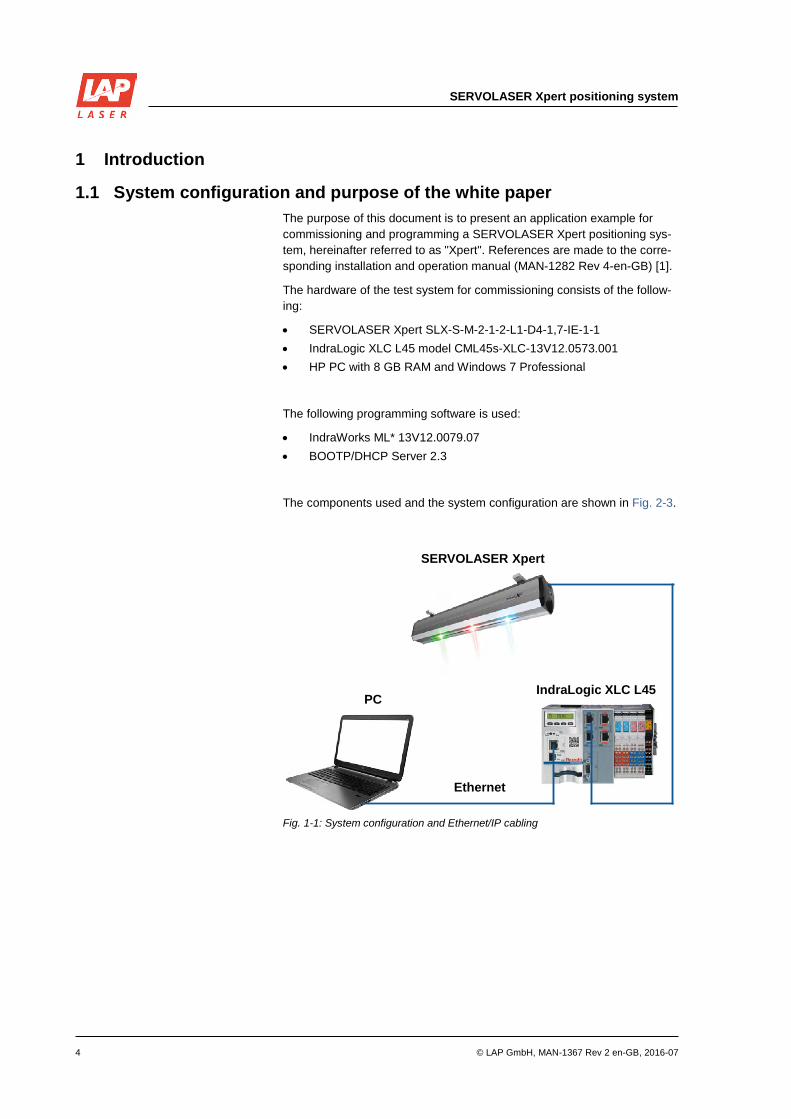
1.1 System configuration and purpose of the white paper The purpose of this document is to present an application example for commissioning and programming a SERVOLASER Xpert positioning sys-tem, hereinafter referred to as "Xpert". References are made to the corre-sponding installation and operation manual (MAN-1282 Rev 4-en-GB) [1].
The hardware of the test system for commissioning consists of the follow-ing:
• SERVOLASER Xpert SLX-S-M-2-1-2-L1-D4-1,7-IE-1-1 • IndraLogic XLC L45 model CML45s-XLC-13V12.0573.001 • HP PC with 8 GB RAM and Windows 7 Professional
The following programming software is used:
• IndraWorks ML* 13V12.0079.07 • BOOTP/DHCP Server 2.3
The components used and the system configuration are shown in Fig. 2-3.
Fig. 1-1: System configuration and Ethernet/IP cabling
SERVOLASER Xpert
IndraLogic XLC L45PC
Ethernet

SERVOLASER Xpert Controlling via IndraLogic XLC L45
© LAP GmbH, MAN-1367 Rev 2 en-GB, 2016-07 5
The Xpert has its own controller with an Ethernet/IP port and two movable laser modules (Fig. 1-2). Two devices can be connected to form a system with up to four movable lasers.
An additional fixed laser, which is installed in the centre, is optional. This fixed laser is positioned above the linear rail. This enables the movable la-ser modules to use the entire travel range.
Three different laser colours are available, i.e. can be configured (red, green, blue). The laser colours can be combined in any way. Maximum visibility in different lighting conditions and on different projection surfaces can be ensured by the choice of laser colour.
The laser modules are available with different aperture angles. The stand-ard aperture angle is 90° for red and green lasers and 70° for blue lasers.
The different laser classes provide different levels of laser power. The maximum possible laser output power of the Xpert is 40 mW. Models with a maximum laser output power corresponding to the permitted limit are available for each laser class. The dimming function allows you to set each individual laser module separately to your optimum visibility.
Fig. 1-2: SERVOLASER Xpert

SERVOLASER Xpert positioning system
6 © LAP GmbH, MAN-1367 Rev 2 en-GB, 2016-07
This white paper is structured to follow the procedure during commission-ing. In principle, a different sequence of steps would be possible in some places, but a modified order of steps during Ethernet/IP configuration and the assignment of IP addresses has generally led to problems. Therefore, it is recommended that you adhere to the sequence of steps specified here.
First you must connect the Xpert directly to the programming PC. This step is necessary because when the Xpert is subsequently connected with the PLC, you will no longer be able to access the integrated web server. Then you assign an IP address for the programming PC and the Xpert as well as check the Ethernet/IP connection.
In the second step, download an electronic data sheet (EDS file) of the Xpert via the Xpert web server. The EDS file contains all communication parameters of the device as well as the available objects. The DeviceNet configuration tool imports the EDS files of the devices available in the net-work and uses them to calculate the configuration data which are subse-quently loaded onto the DeviceNet participants.
In the third step, connect the system cables as shown in Fig. 1-1. You then assign an IP address for the programmable logic controller. After that the IP address of the programming PC must be adapted to the IP address of the PLC.
In the fourth step, create a new IndraWorks project and add the hardware. Select the IndraLogic XLC L45 used here as the device type and define the IP address. Only the two real-time Ethernet interfaces X7E3/X7E4 are needed for the interfaces. Next to the port designation, select an Ether-net/IP scanner, which functions as a master here. Once you have com-pleted the configuration, you must set the Ethernet/IP scanner parameters and import the previously downloaded EDS file.
The last chapter of the white paper shows an application example for con-trolling the movements. It deals with the creation of a variable table for controlling the incoming data packets and for reading the outgoing data packets of the Xpert. It also describes the procedure for loading the project onto the programmable logic controller.
All steps from configuring the Ethernet/IP to creating the finished program are described in detail in the following chapters.

SERVOLASER Xpert Controlling via IndraLogic XLC L45
© LAP GmbH, MAN-1367 Rev 2 en-GB, 2016-07 7
2 Configuring the Ethernet/IP connection
2.1 Assigning an IP address for the programming PC First you must connect the Xpert directly to the programming PC as shown in Fig. 2-1. This is the only way to access the integrated web server of the Xpert and download the EDS file.
Fig. 2-1: Connection between Xpert and programming PC
To assign IP addresses, in this case the IP address of the Xpert, you must first appropriately set the IP address of the programming PC. In this appli-cation example the IP address 192.168.200.20 was assigned to the pro-gramming PC. This is done as shown in Fig. 2-2:
Control Panel > Network and Internet > Network and Sharing Center > Change adapter settings > Local Area Connection > Properties – Internet Protocol Version 4 (TCP/IPv4) > Properties > Use the following IP address: 192.168.200.20 > OK
Ethernet
PC
SERVOLASER Xpert

SERVOLASER Xpert positioning system
8 © LAP GmbH, MAN-1367 Rev 2 en-GB, 2016-07
Fig. 2-2: LAN connection and Internet protocol properties on the PC

SERVOLASER Xpert Controlling via IndraLogic XLC L45
© LAP GmbH, MAN-1367 Rev 2 en-GB, 2016-07 9
2.2 Assigning an IP address to the Xpert using BOOTP/DHCP Server Next, assign an IP address to the Xpert via the BOOTP/DHCP Server software. When the BOOTP/DHCP Server 2.3 software is started, it scans the MAC addresses of all connected devices (Fig. 2-3). The identified par-ticipants and their MAC addresses are displayed in the Request History window. Select the Xpert MAC address and click Add to Relation List to confirm.
Fig. 2-3: Search for the Xpert MAC address using BOOTP/DCHP Server 2.3
Then BOOTP/DHCP prompts you to enter the IP address (Fig. 2-4), which must be in the same subnet as the programming PC. In our application example IP address 192.168.200.21 was assigned to the Xpert. If the en-try has been confirmed, the MAC address and IP address are displayed in the Relation List window. If everything was successful, the [Enable DHCP] Command successful message is displayed in the Status window at the bottom left of the screen (Fig. 2-5).
Following this message, a ping can be sent from the DOS window to the Xpert to check accessibility (Fig. 2-6).

SERVOLASER Xpert positioning system
10 © LAP GmbH, MAN-1367 Rev 2 en-GB, 2016-07
Fig. 2-4: Assigning an IP address to the Xpert using BOOTP/DHCP Server 2.3
Fig. 2-5: BOOTP/DHCP Server after DHCP activation
Fig. 2-6: Checking the accessibility of the Xpert by sending a "ping"

SERVOLASER Xpert Controlling via IndraLogic XLC L45
© LAP GmbH, MAN-1367 Rev 2 en-GB, 2016-07 11
2.3 Downloading the Xpert EDS file In order to include the Xpert EDS file in the IndraWorks project later, you must first download it from the integrated Xpert web server. To do so, open a web browser and enter the IP address of the Xpert (see chapter 2.2) as the web address.
Right-click the file and select Save target as to download the EDS file (Fig. 2-7 and Fig. 2-8).
Fig. 2-7: Xpert web server
Fig. 2-8: Downloading the Xpert EDS file

SERVOLASER Xpert positioning system
12 © LAP GmbH, MAN-1367 Rev 2 en-GB, 2016-07
2.4 Cabling and configuration of the overall system After you have successfully downloaded the EDS file from the integrated web server, connect the cables of the overall system as shown in Fig. 1-1. Then set the Ethernet X7E5 programming interface to which the pro-gramming PC is connected to the programmable logic controller using the arrow buttons (Fig. 2-9) [2,3]. In our application example IP address 192.168.1.32 is assigned to the programming interface. It is important that this IP address be located in a different subnet to the IP address of the Xpert, since otherwise IP communication conflicts could occur.
Fig. 2-9: Configuration of the Ethernet X7E5 programming interface
Then you must reassign the IP address of the programming PC in the subnet of the programmable logic controller. The procedure for assigning a new IP address to the programming PC is described in chapter 2.1. In our application example the new IP address 192.168.1.10 is assigned to the programming PC. Tab. 2-1 shows all assigned IP addresses and the corresponding systems.
System IP address
Programming PC 192.168.1.10
Programmable logic controller 192.168.1.33
SERVOLASER Xpert 192.168.200.21
Tab. 2-1: All assigned IP addresses

SERVOLASER Xpert Controlling via IndraLogic XLC L45
© LAP GmbH, MAN-1367 Rev 2 en-GB, 2016-07 13
3 Creating an IndraWorks project If the cables of the overall system have been connected and an IP ad-dress has been assigned to each system, you can then open the In-draWorks software and create a new project [4,5]. In the Project Ex-plorer in the left column, right-click the project name and select Add > IndraLogic XLC L45 (Fig. 3-1).
Fig. 3-1: Creating a new project in IndraWorks

SERVOLASER Xpert positioning system
14 © LAP GmbH, MAN-1367 Rev 2 en-GB, 2016-07
This automatically opens a window for configuring IndraLogic XLC L45 (Fig. 3-2).
In the Step 2: Configuration window, specify the firmware version as well as the IP address and type of the device. The IP address was already as-signed in chapter 2.4 and must only be copied to the software. In our ap-plication example IP address 192.168.1.33 is entered. You can then exe-cute a connection test in this window.
Fig. 3-2: Configuring IndraLogic XLC L45
When you have copied the settings and successfully executed the connec-tion test, you configure the ports in the next window, Step 3: Interfaces (Fig. 3-3). In our application example only the two Realtime Ethernet interfaces X7E3/X7E4 are needed. In the selection list next to the port designation, select an Ethernet/IP Scanner, which functions as a master here. Then click Finish to complete the configuration.

SERVOLASER Xpert Controlling via IndraLogic XLC L45
© LAP GmbH, MAN-1367 Rev 2 en-GB, 2016-07 15
Fig. 3-3: Configuring the interfaces
You have successfully created the project and now you can open it in the Project Explorer. The Ethernet/IP scanner was also created (Fig. 3-4). You need only to set its parameters.
Fig. 3-4: Ethernet/IP Scanner has been created successfully
Double-click the Ethernet/IP scanner to open the Scanner settings tab (Fig. 3-5). Select the Used fixed IP-Address: option. The IP address must be in the same subnet as the IP address of the Xpert. In our applica-tion example the address 192.168.200.100 is selected, since the address 192.168.200.21 was assigned to the Xpert in chapter 2.2.

SERVOLASER Xpert positioning system
16 © LAP GmbH, MAN-1367 Rev 2 en-GB, 2016-07
Fig. 3-5: Configuring the Ethernet/IP scanner
After a new IndraWorks project has been created and the Ethernet/IP scanner has been configured, you can now import the Xpert EDS file. To do so, from the main menu select Tools and then the Device Data-base tab (Fig. 3-6).
Fig. 3-6: Opening the device database
You can install and uninstall device description files in the device data-base. The devices which are currently installed are listed in the Available devices section. To add a new device, click Add Devices (Fig. 3-7).

SERVOLASER Xpert Controlling via IndraLogic XLC L45
© LAP GmbH, MAN-1367 Rev 2 en-GB, 2016-07 17
Fig. 3-7: Device database
First select the EDS and DCF files search option. Then select the Xpert EDS file and click Open to add it (Fig. 3-8).
Fig. 3-8: Opening the Xpert EDS file
The Xpert has now been automatically added to the list of available devic-es.

SERVOLASER Xpert positioning system
18 © LAP GmbH, MAN-1367 Rev 2 en-GB, 2016-07
Fig. 3-9: Updated device database
To add the Xpert to the project, right-click the Ethernet/IP scanner in the Project Explorer and select the following path (Fig. 3-10):
Add > Add device > Generic Device > ServoXpert Ether-Net/IP
Fig. 3-10: Adding the Xpert to the project
The device has now been added. Double-click the ServoX-pert_Ethernet/IP in the Project Explorer to set the Xpert param-eters. The IP address here must match the configured address of the Xpert (Fig. 3-11). In our example, the IP address is 192.168.200.21.

SERVOLASER Xpert Controlling via IndraLogic XLC L45
© LAP GmbH, MAN-1367 Rev 2 en-GB, 2016-07 19
Fig. 3-11: Configuring the Xpert
Then select the Connections tab and click Add Connection (Fig. 3-12).
Fig. 3-12: Add Connection
Here you must click the Exclusive Owner row. In the New connection window, make the following settings as shown in Fig. 3-13:
• Due to the program cycle time, set RPI to 20ms • Set the Target to Scanner text box to 256 bytes
Leave the default values for the remaining setting options.

SERVOLASER Xpert positioning system
20 © LAP GmbH, MAN-1367 Rev 2 en-GB, 2016-07
Fig. 3-13: Connection settings
When you create a new connection with the settings shown, the input and output words on the EthernetIP I/O Mapping tab are also automati-cally created. The Always update variables option must always be ticked (Fig. 3-14). The definition and structure of the input and output data words for controlling and monitoring the Xpert are described in the rele-vant installation and operation manual (MAN-1282 Rev 4-en-GB). This ends the hardware configuration. The last chapter of the white paper shows an application example for controlling the Xpert.
Fig. 3-14: EthernetIP I/O Mapping

SERVOLASER Xpert Controlling via IndraLogic XLC L45
© LAP GmbH, MAN-1367 Rev 2 en-GB, 2016-07 21
4 Application example
4.1 Creating the variable table The Xpert can be controlled only byte by byte via the EthernetIP I/O Mapping of the Ethernet/IP scanner. For this reason a variable table is created in this step. With this table you can more easily and more conven-iently control and read the individual variables of the incoming and out-going data packets.
To create the table, in the Project Explorer double-click the PlcProg (PRG) module (Fig. 4-1).
Fig. 4-1: Creating the variable table in the PlcProg module
You declare the input and output variables in this module. The variables are described in the relevant installation and operation manual (MAN-1282 Rev 4-en-GB). Fig. 4-2 and Fig. 4-3 show the declared input and output variables.
Fig. 4-2: Declared output variables
SERVOLASER Xpert positioning system
22 © LAP GmbH, MAN-1367 Rev 2 en-GB, 2016-07
Fig. 4-3: Declared input variables
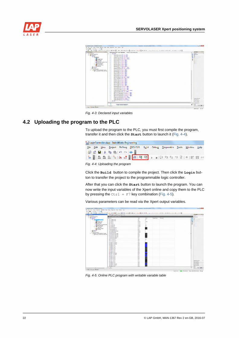
4.2 Uploading the program to the PLC To upload the program to the PLC, you must first compile the program, transfer it and then click the Start button to launch it (Fig. 4-4).
Fig. 4-4: Uploading the program
Click the Build button to compile the project. Then click the Login but-ton to transfer the project to the programmable logic controller.
After that you can click the Start button to launch the program. You can now write the input variables of the Xpert online and copy them to the PLC by pressing the Ctrl + F7 key combination (Fig. 4-5).
Various parameters can be read via the Xpert output variables.
Fig. 4-5: Online PLC program with writable variable table

SERVOLASER Xpert Controlling via IndraLogic XLC L45
© LAP GmbH, MAN-1367 Rev 2 en-GB, 2016-07 23
5 Summary This white paper presents an application example for commissioning and programming a SERVOLASER Xpert positioning system in connection with a Bosch Rexroth IndraLogic XLC L45 control system.
The first chapter describes the hardware and software used as well as the purpose of the white paper. It also provides general information about the Xpert.
The second chapter describes the settings of the Ethernet/IP connection on the programming PC as well as the assignment of IP addresses using the BOOTP/DHCP Server software. It then describes the downloading of the Xpert EDS file from the integrated web server to the programming PC. The last part of the second chapter describes the cabling and configura-tion of the overall Ethernet/IP network.
The third chapter describes the creation of a new IndraWorks project, which contains the configuration of the programmable logic controller, the configuration of the Ethernet/IP scanner which functions as the master, as well as incorporation of the downloaded EDS file in the IndraWorks pro-ject. In addition it describes the settings and adding of a new connection with the Xpert.
The last chapter describes an application example for controlling the Xpert. It deals with the creation of a variable table for controlling the in-coming data packets and for reading the outgoing data packets of the Xpert. In addition it describes the procedure for uploading data to the pro-grammable logic controller. In principle the Xpert and the Bosch Rexroth IndraLogic XLC L45 software have always worked together without prob-lems or errors when the Ethernet/IP protocol is used and when the rele-vant installation and operation manual (MAN-1282 Rev 4-en-GB) and the points described in this white paper are adhered to.

SERVOLASER Xpert positioning system
24 © LAP GmbH, MAN-1367 Rev 2 en-GB, 2016-07
6 References [1] Installation and Operation Manual "MAN-1282 Rev 4-en-GB", LAP
GmbH, Lüneburg, 2015
[2] Rexroth IndraLogic XLC 11 VRS – First Steps, Bosch Rexroth AG, Lohr am Main, 2010
[3] Rexroth IndraLogic XLC 11 VRS – System Overview, Bosch Rexroth AG, Lohr am Main, 2011
[4] Rexroth IndraWorks 11 VRS – Software Installation, Bosch Rexroth AG, Lohr am Main, 2010
[5] Rexroth IndraWorks 11 VRS – Engineering, Bosch Rexroth AG, Lohr am Main, 2011