controlled/‘living’ polymerization methods -...
TRANSCRIPT

Controlled/‘living’ polymerizationmethods
WAY N E H AY E S a n d S T E V E R A N NA R D
1. IntroductionChain-growth polymerizations such as free-radical polymerizations are char-acterized by four key processes:(i) initiation, (ii) propagation, (iii) chaintransfer, and (iv) termination.1 If it is possible to minimize the contribution ofchain transfer and termination during the polymerization, it is possible toachieve a level of control over the resulting polymer and achieve a predeter-mined number average molecular weight and a narrow molecular weight dis-tribution (polydispersity). If such an ideal scenario can be created, thenumber of polymer chains that are produced is equal to the number of initi-ator groups; the polymerization will proceed until all of the monomer hasbeen consumed and the polymer chain ends will remain active so that furtheraddition of monomer will lead to continued polymerization. This type ofpolymerization was termed a ‘living’ polymerization by Szwarc2 in 1956 andrepresents one of the ultimate goals of synthetic polymer chemists. Flory3
determined that in the absence of termination, the number of propagatingpolymer chains must remain constant and that the rate of polymerization foreach growing chain must be equal. In this situation, the number averagedegree of polymerization (DPn) and hence the molecular weight of the poly-mer can be predicted by simple consideration of the monomer to initiatorratio (see eqns (1) and (2), respectively).
(1)
Number average molecular weight (polymer) �DPn � molecular weight (monomer) (2)
Several key criteria are used to elucidate the ‘living’ nature of apolymerization.4 For a polymerization to be considered ‘living’, the rate ofinitiation must exceed the rate of propagation. Therefore, all the propagatingpolymer chains are formed simultaneously and grow at the same rate. If this
DPn �[monomer][initiator]
3

situation did not occur, the first chains formed would be longer than thoseinitiated later and the molecular weight distribution of the propagating chainswould broaden. In addition, an ideal ‘living’or ‘immortal’polymerization mustnot exhibit any termination of the propagating polymer chains over the lifetimeof the reaction. Consequently, ‘living’ polymerizations are characterized byvery narrow molecular weight distributions (Mw/Mn � 1.2). The ability of thepropagating species to undergo polymerization until full monomer conversion
W. Hayes and S. Rannard
100
X
Functional group
Polymer X
Functional groups
PolymerX
End-functionalized polymers Bifunctional/telechelic polymers
AB block copolymers ABA block copolymers
Polymer A
Polymer B
Polymer B
Polymer A
Graft/brush polymers Ladder-type polymers
Star polymers
A ABA B
Fig. 3.1 The variety of polymer and copolymer architectures that can be synthesized by‘living’ polymerization techniques.
and then to continue polymerizing upon addition of another monomerfeed is another key feature of ‘living’ polymerizations (i.e. the active chainends are stable enough to enable synthesis of block copolymers via sequentialmonomer addition). If all of these criteria have been satisfied, polymers andblock copolymers exhibiting Poisson-type molecular weight distributions willbe produced and a linear relationship exists between the number averagemolecular weight (Mn) of the resultant polymer and monomer conversion.
As a consequence of the development of ‘living’ polymerization methodo-logies, synthetic polymer chemists are now able to construct, in a precise man-ner, a wide variety of polymer architectures5 (Figure 3.1) that were previouslyinaccessible using uncontrolled chain-growth methods such as free-radicalpolymerizations that employed initiators such as azobisisobutyronitrile(AIBN) or benzoyl peroxide.6 For example, in light of recent developments in‘living’ anionic polymerization techniques, ABA block copolymers such asstyrene–butadiene–styrene for use in thermoplastic elastomers can be pro-duced in a reliable fashion on an industrial scale.5 The implications of ‘living’polymerization methods upon materials science are enormous, as syntheticpolymer chemists now have a range of powerful synthetic tools available tothem to facilitate the construction of well-defined polymers almost to order. Inthis respect, meaningful structure–property relationships (analogous to thoseemployed in drug discovery by the pharmaceutical industry) can be carried outfor the first time, enabling detailed development of high technology polymericmaterials.
2. Covalent ‘living’ polymerization: group transferpolymerization
Several ‘living’ polymerization techniques have been shown to initiate andpropagate by the reaction of an active covalent end group with monomers.One such method is the Group Transfer Polymerization (GTP). This poly-merization technique, first described by Webster and co-workers7 from theresearch laboratories of DuPont, employs silyl ketene acetals in the covalent‘living’ polymerization of a variety of alkylated methacrylates (Scheme 1).Initiation involves Michael-type addition of the monomer to the silyl keteneacetal. The monomer adduct thus formed rapidly adds more monomer in arepetitive Michael-type addition process to afford the desired polymer. Theterm GTP was adopted to indicate that the silyl group of the silyl keteneacetal initiator system has been transferred to the terminal moiety of thepropagating polymer and subsequently to the monomer that is undergoingaddition. Each transfer of the silyl group to the monomer regenerates a silylketene acetal group at the end of the propagating chain. The polymerizationmechanism has received extensive investigation and, to date, a definitivemechanism is yet to receive universal acceptance. Several mechanisms torationalize the polymerization characteristics have been proposed, including
3: Controlled/‘living’ polymerization methods
101

associative and dissociative and pseudo anionic pathways. However, the focusof this chapter does not permit an extensive discussion of the various mecha-nistic proposals and the reader is referred to the literature for more details.7–12
W. Hayes and S. Rannard
102
ORO+ +
OSiMe3MeO
OR
RO O
OSiMe3
MeO2C
MeO2C
OSiMe3
OR
n
OROn
CatalystInitiator
Methacrylic polymer
Nu–
Scheme 1 GTP of methacrylic monomers.
Silyl ketene acetals are relatively stable species and require activation by acatalyst in order to initiate polymerization of ,�-unsaturated monomers.Numerous catalysts for GTP polymerizations have been examined7,13,14 andthese studies have revealed that bifluorides and bioxyanions such astris(dimethylamino) sulfonium bifluoride (TASHF2) and tetra-n-butyl ammo-nium bibenzoate (TBABB), respectively, afford optimum polymerizationcharacteristics. (Note: Bifluoride based catalysts are not soluble in tetra-hydrofuran (THF) and thus acetonitrile is used as the solvent in these cases;in general TBABB is the optimum catalyst as it is readily soluble in THF andaffords better control of molecular weight, conversion, and polydispersity.)GTP has been shown to be robust (Mw/Mn � 1.1) and is compatible withnumerous ,�-unsaturated monomers including acrylates, ketones, lactones,and polyunsaturated esters such as ethyl sorbate. Many of these polymeriza-tions can be carried out at ambient temperatures, but the method can also beperformed using elevated temperatures. In addition, GTP is suitable for usewith a wide range of reaction solvents of varying polarity (ranging from n-heptane to THF, although note that the protic and electron donor solventsare not suitable for GTP).
Although GTP demonstrates the fundamental characteristics of a ‘living’polymerization, namely narrow molecular weight distribution, control ofmolecular weight derived from the monomer/initiator stoichiometry, and the

ability to construct block copolymers, the technique is not foolproof and isinhibited by the presence of moisture and inherent termination reactions suchas isomerization and backbiting.
Protocol 1.
Synthesis of the GTP catalyst TBABB (Scheme 2)
This method for the preparation of TBABB is based upon the proceduredescribed by Dicker et al .13,14
Scheme 2 Preparation of TBABB catalyst.
Caution! Carry out all procedures in a well-ventilated fume-cupboard, wearappropriate disposable gloves, a lab-coat, and safety glasses. All vacuum-linework should be performed while standing behind a protective Perspex screen.Never use flat-bottomed flasks with rotary evaporators.
Equipment● Separating funnel (250 mL)● Erlenmeyer flask (250 mL)● Sintered-glass filter funnel (porosity 2)● Single-necked round-bottomed flask (500 mL)
Materials● Benzoic acid, 20.0 g, 164 mmol irritant, harmful if swallowed and by inhalation● Tetra n-butyl ammonium hydroxide, 40% w/v aq., causes burns, harmful by inhalation
80 mL● Dichloromethane, 3 � 50 mL carcinogen, harmful by inhalation● Anhydrous magnesium sulfate, ca. 15 g harmful by inhalation● THF solvent, 250 mL irritant, highly flammable may form explosive peroxides● Diethyl ether for precipitation, 300 mL irritant, highly flammable
Method
1. To a separating funnel (250 mL), add benzoic acid (10 g, 82 mmol) and tetra-n-butyl ammonium hydroxide solution (40% w/v aq., 80 mL) and vigorouslyshake the mixture until all of the acid has dissolved. Vent the separating fun-nel at regular intervals to prevent the build-up of excessive pressure in theseparating funnel.
2. Extract the aqueous phase with dichloromethane (3 � 50 mL) and combinethe organic extracts in an Erlenmeyer flask (250 mL).
3. Add benzoic acid (10 g, 82 mmol) to the organic extracts and stir with a glassrod to ensure complete dissolution of the acid.
4. Dry the organic phase with anhydrous magnesium sulfate (ca. 15 g, 30 min).
O
OH(n Bu)4NOH
++
CH2Cl2 O
O
O
OH(nBu)4N
+––
3: Controlled/‘living’ polymerization methods
103
Protocol 1. Continued
5. Filter the ‘dried’ organic phase at the pump through a sintered-glass filterfunnel, transfer the solution to a single-necked, round-bottomed flask(500 mL) and concentrate the solution in vacuo using a rotary evaporator.
6. Dissolve the residual solid in warm THF (ca. 250 mL) and concentrate the solu-tion until half of the volume of solvent remains using a rotary evaporator.
7. To this concentrated solution, slowly add diethyl ether (ca. 250 mL) until afine white crystalline product is observed. Filter the organic phase at thepump through a sintered-glass filter funnel and wash the product withdiethyl ether (ca. 50 mL).
8. Transfer the white crystalline product to a clean, dry single-necked, round-bottomed flask (100 mL) and dry using a vacuum line. Yields ca. 90% aretypical.
Protocol 2.
GTP of methyl methacrylate (Scheme 1)
Caution! Carry out all procedures in a well-ventilated fume-cupboard,wear appropriate disposable gloves, a lab-coat, and safety glasses. All vacuum-line work should be performed while standing behind a protective Perspexscreen.
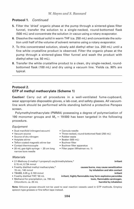
Polymethylmethacrylate (PMMA) possessing a degree of polymerization of190 monomer groups and Mn � 19 000 has been targeted in the followingprocedure.
Equipment● Dual manifold (nitrogen/vacuum) ● Cannula needle● Vacuum source ● Three-necked, round-bottomed flask (250 mL)● Source of dry nitrogen ● Rubber septa● Hotplate stirrer ● Beaker (500 mL)● Teflon-coated magnetic stirrer bar ● Buchner filter● Contact thermocouple ● Buchner filter apparatus● 20 mL gas-tight syringe � 20 cm long ● Filter paper (Whatman no. 1)
narrow bore needle
Materials● [(1-Methoxy-2-methyl-1-propenyl) oxy]trimethylsilane,a irritant
0.15 ml, 0.734 mmol● Freshly distilled methyl methacrylate,b causes burns, may cause sensitization
15 mL, 140 mmol by inhalation and skin contact● TBABB, 0.05 g, 0.103 mmol irritant● Freshly distilled THF,c 50 mL irritant, highly flammable may form explosive peroxides● Methanol for precipitation, ca. 700 mL toxic, flammable carcinogen,
Chloroform, ca. 20 mL harmful by inhalation
Note: Silicone grease should not be used to seal reaction vessels used in GTP methods. Employapiezon type greases or fine teflon tape instead.
W. Hayes and S. Rannard
104

Method
1. Vacuum distil THF (50 mL) directly into a clean, dry three-necked, round-bottomed flask (250 mL)—the reaction flask. Purge the flask with dry nitrogenand allow the solvent to warm to room temperature. Remove a stopper andseal with an appropriate rubber septum.
2. Cannulate [(1-methoxy-2-methyl-1-propenyl)oxy]trimethylsilane (0.15 ml,0.734 mmol) from a graduated 2 mL Schlenk flask using a transfer needle (orcannula) (using this technique it is possible to add the initiator to an accuracyof �0.05 mL) by applying pressure from the nitrogen supply as shown inFigure 3.2.
3. Remove the septum and add tetra n-butyl ammonium bibenzoate (seeProtocol 1) (0.05 g, 0.103 mmol) to the solution whilst maintaining a positivenitrogen pressure. Once the addition is complete, seal the flask with anappropriate rubber septum.
4. Stir the solution for approximately 2 min before adding freshly distilledmethyl methacrylate (15 mL, 140 mmol) in a dropwise fashion via a cannulaor a gas-tight syringe to the reactor flask at a rate of approximately 1 mL/min.
5. Monitor the exotherm using a contact thermometer (attach the contactthermometer to the side of the reactor)—typical temperatures reached varybetween 45 and 60�C.
6. Once the reaction has cooled to room temperature, add methanol (ca. 5 mL)to the reaction mixture in order to terminate the polymerization.
7. Purify and recover the resultant polymer by precipitation using drop-wiseaddition of the THF solution into the vortex walls of a rapidly stirred ten-foldexcess of cold methanol (ca. 500 mL). A brilliant white fine precipitate should
3: Controlled/‘living’ polymerization methods
105
xx.x°C
N2N2
Freshly distilled[(1Methoxy-2-methyl-1-propenyl)
oxy] trimethylsilane
Cannulaneedle
GraduatedSchlenk tube
Contactthermometer
Rubbersepta
Rubberseptum
Inletneedle
Outletneedle
Stirrerbar
Reactionflask
Fig. 3.2 Transfer of initiator/catalyst/solvent to reaction flask.

Protocol 2. Continued
be produced. Filter the polymer at the pump through a sintered-glass filterfunnel, transfer the solid obtained to a large watch glass and dry it in a vacuumoven at 50�C for at least 4 h. Once a consistent weight is achieved, record thecrude yield. Yields �95% are typical.
8. Transfer the crude polymer into a 100 mL beaker and dissolve it in chloro-form (ca. 10–20 mL). Precipitate the polymer in the same manner asdescribed in step 7 by drop-wise addition of the chloroform solution to a ten-fold excess of cold methanol. Filter the polymer at the pump through asintered-glass filter funnel, transfer the solid obtained to a large watch glassand dry it in a vacuum oven at 50�C for at least 8 h. Once a constant weight isachieved, record the yield of the brilliant white powder.
9. Analyse the product using gel permeation chromatography (GPC) calibratedwith a range of PMMA narrow standards to determine Mn and Mw/Mn.
aThe group transfer initiator [(1-methoxy-2-methyl-1-propenyl)oxy]trimethylsilane is commerciallyavailable although it can be synthesized from methyl isobutyrate by following the procedure firstdescribed by Ainsworth et al.15 and the modification developed by Eastmond and Grigor.16 The initi-ator, either synthesized or purchased, should be distilled under vacuum into a 2 mL graduated Schlenkflask with 0.1 mL graduations and stored under nitrogen.bMethyl methacrylate should be passed through a basic alumina column directly into a Schlenk flaskcontaining CaH2 and stored in the fridge. Methyl methacrylate should be distilled with care, directlyfrom the CaH2 under high vacuum and used immediately.cTHF is distilled as follows: allow the solvent to stand over sodium wire until no further evolution of gasis observed. Transfer the pre-dried THF to a still containing sodium wire/benzophenone and bring thesolvent to reflux under a stream of dry nitrogen until the deep purple colour of the sodium benzophe-none ketyl persists—this indicates that the THF is anhydrous. Under a flow of dry nitrogen, collect thedry THF into a clean dry flask that contains sodium wire and then distill the required volume directlyinto the polymerization vessel under vacuum immediately prior to use.
Protocol 3.
Block copolymer synthesis using GTP: synthesis of poly(methyl
methacrylate-b-n-butyl methacrylate) (Scheme 3)
Caution! Carry out all procedures in a well-ventilated fume-hood, wearappropriate disposable gloves, a lab-coat, and safety glasses. All vacuum-linework should be performed while standing behind a protective Perspexscreen.
This procedure is carried out in exactly the same way as described in Protocol 2.However, in this approach, once complete conversion of the initial monomerfeed has been attained (as determined by GPC analysis) a second monomer isadded to the reactor flask. Since the polymerization exhibits ‘living’ character-istics, active polymer chain ends still exist in the monomer ‘starved’ flask andfurther addition of another monomer enables the polymerization to continue,therefore producing an AB block copolymer.
W. Hayes and S. Rannard
106

Scheme 3 Synthesis of poly(methyl methacrylate b-n-butyl methacrylate) using GTP.
Equipment● Dual manifold (nitrogen/vacuum) ● Cannula needle● Vacuum source ● Three-necked, round-bottomed flask (250 mL)● Source of dry nitrogen ● Rubber septa● Hotplate stirrer ● Beaker (500 mL)● Teflon-coated magnetic stirrer bar ● Buchner filter● Contact thermocouple ● Buchner filter apparatus● 0.5 mL gas-tight syringe � 20 cm long narrow ● Filter paper (Whatman no. 1)
bore needle
Materials● (1-Methoxy-2-methyl-1-propenyl)oxy]trimethylsilane,a irritant
0.15 mL, 0.734 mmol● Freshly distilled methyl methacrylate,b causes burns, may cause sensitization
15 mL, 140 mmol by inhalation and skin contact● TBABB, 0.05 g, 0.103 mmol irritant● Freshly distilled n-butyl methacrylate,b causes burns, may cause sensitization
22.5 mL, 140 mmol by inhalation and skin contact● Freshly distilled THF,c 150 mL irritant, flammable● Methanol for precipitation, ca. 700 mL toxic, highly flammable may form explosive peroxides● Chloroform, ca. 20 mL carcinogen, harmful by inhalation
Method
1. Vacuum distil THF (50 mL) directly into a clean, dry three-necked, round-bottomed flask (250 mL)—the reaction flask. Purge the flask with dry nitro-gen and allow the solvent to warm to room temperature. Remove a stopperand seal with an appropriate rubber septum.
2. Cannulate [(1-methoxy-2-methyl-1-propenyl)oxy]trimethylsilane (0.15 mL,0.734 mmol) from a graduated 2 mL Schlenk flask using a transfer needle(or cannula) (using this technique it is possible to add the initiator to anaccuracy of �0.05 mL) by applying pressure from the nitrogen supply asshown in Figure 3.2.
O
O
O
OH(nBu)4N
OMeO
+OSiMe3MeO OMe
MeO O
OSiMe3MeO2C
MeO2C
n
O OBun
n
CatalystInitiatorPoly(methyl methacrylate)
MeO On
m
OBun
OSiMe3
BunO Om
Poly(methyl methacrylate-b-n-butyl methacrylate)
+
3: Controlled/‘living’ polymerization methods
107

Protocol 3. Continued
3. Remove the septum and add TBABB (see Protocol 1) (0.05 g, 0.103 mmol) tothe solution whilst maintaining a positive nitrogen pressure. Once the addi-tion is complete, seal the flask with an appropriate rubber septum.
4. Stir the solution for approximately 2 min before adding freshly distilledmethyl methacrylate (15 mL, 140 mmol) in a drop-wise fashion via a cannulaor a gas-tight syringe to the reactor flask at a rate of approximately 1 mL/min.
5. Monitor the exotherm using a contact thermometer (attach the contactthermometer to the side of the reactor)—typical temperatures reached varybetween 45 and 60�C.
6. Once the reaction has cooled to room temperature, remove an aliquot of thereaction mixture and add it to a small amount of methanol to terminate thepolymerization of the aliquot. Analyse the aliquot by GPC to determine the success of the initial polymerization.
7. Add freshly distilled n-butyl methacrylate (22.5 mL, 140 mmol) in a drop-wisefashion via a cannula to the reactor flask.
8. Determine successful reinitiation by monitoring the exotherm of the secondpolymerization. When the reaction mixture has returned to room temperatureadd methanol (ca. 5 mL) in order to terminate the polymerization.
9. Purify and recover the resultant polymer by precipitation using drop-wiseaddition of the THF solution into the vortex walls of a rapidly stirred ten-foldexcess of cold methanol (ca. 500 mL). A brilliant white fine precipitateshould be produced. Filter the polymer at the pump through a sintered-glass filter funnel, transfer the solid obtained to a large watch glass and dryit in a vacuum oven at 50�C for at least 4 h. Once a consistent weight isachieved, record the crude yield. Yields �95% are typical.
10. Transfer the crude polymer into a 100 mL beaker and dissolve it in chloro-form (ca. 10–20 mL). Precipitate the polymer in the same manner asdescribed in step 9 by drop-wise addition of the chloroform solution to a ten-fold excess of cold methanol. Filter the polymer at the pump through a sintered-glass filter funnel, transfer the solid obtained to a large watchglass and dry it in a vacuum oven at 50�C for at least 8 h. Once a constantweight is achieved, record the yield of the brilliant white powder.
11. Analyse the product using GPC calibrated with a range of PMMA narrowstandards to determine Mn and Mw/Mn and also compare the product Mn tothe homopolymer aliquot removed after the first polymerization.
aSee Protocol 2.bMethacrylate monomers should be passed through a basic alumina column directly into a Schlenkflask containing CaH2 and stored in the fridge. The monomer should be directly distilled carefully fromthe CaH2 under high vacuum and used immediately.cSee Protocol 2.
W. Hayes and S. Rannard
108

3. Controlled free-radical polymerizations mediated by nitroxides
The nature of free-radical polymerization has traditionally hindered attemptsto produce an ideal ‘living’ free radical polymerization technique. It is verydifficult to prevent chain transfer and termination reactions in free-radicalpolymerizations and although several methods have afforded polymers withvery low polydispersities (Mw/Mn � 1.1), these approaches are often referredto as ‘controlled’ polymerizations rather than ‘living’ in the literature.
In the early 1980s, Moad et al.17 initially attempted to control free-radicalpolymerization using stable free radicals such as nitroxides. Following devel-opmental work by Georges et al. at Xerox,18 the approach has led to the real-ization of a diverse range of polymer architectures19–21 that were previouslyunobtainable using traditional anionic or cationic polymerization techniques.
Polymerizations of this type involve interactions between two types ofradical species:(i) transient and (ii) stable (or persistent). The stable radicalscan combine with highly reactive transient radicals to form the so-called‘dormant’ adducts as part of a dynamic equilibrium. In this dormant state,both radical species are effectively inactive and cannot participate inreactions with other reactive radicals. The dormant species, however, may becontrollably dissociated to yield the transient and stable species. After disso-ciation, the transient radical at the end of the growing polymer chain reactsrapidly with vinyl monomers to form polymer chains. If the concentration ofthe stable radical species is high enough, the transient radical at the end of thegrowing chain reacts with the free stable radical to ‘cap’ the growing end ofthe polymer chain and reform the dormant species. The continued formationand capping of the transient species during polymerization, minimizes itsconcentration and, therefore, reduces the occurrence of termination reactionsand produces ‘living’ conditions.
In contrast to the GTP polymerization methods described above, con-trolled free-radical polymerizations involving nitroxides typically employa unimolecular initiator22,23 (as shown in Scheme 4) with the monomer with-out the need for a catalyst. The unimolecular initiator incorporates a latentnitroxide free radical that is more stable than the propagating polymer rad-ical. The C–O bond between the nitroxide unit and the ‘masked’ initiatingcarbon centre is thermally labile (dissociation occurs at approximately125�C). Therefore, polymerizations of this type are simply carried out by dis-solving the initiator in the bulk monomer and heating the mixture to tempera-tures �125�C. The highly reactive vinylic radical liberated can thusparticipate in propagation with the monomer and the stable free nitroxideradical ‘mediates’ the polymerization by repetitive recombination and disso-ciation with the growing polymer chain. Consequently, a degree of control ofthe free-radical polymerization is achieved with defined molecular weightand narrow polydispersities (Mw/Mn � 1.1) of the polymers being obtained.
3: Controlled/‘living’ polymerization methods
109

Scheme 4 Polymerization of styrene using a nitroxide-based unimolecular initiator.
Alternative bimolecular methods have been reported17 that involve mixingappropriate ratios of monomer with free-radical initiators (such as benzoylperoxide) and an excess of the nitroxide stable free-radical moiety. Suchbimolecular methods do not afford the same degree of control of molecularweight and polydispersity since the stoichiometry of the mediating systemcannot be accurately defined, which is a crucial factor in these controlledpolymerization systems. A wide variety of unimolecular nitroxide basedinitiator systems have been described in the literature with those based uponthe 2,2,6,6-tetramethylpiperidinyl-1-oxy (TEMPO) group proving to be themost commonly used.
While possessing many of the key advantages of controlled/‘living’ poly-merization methods, nitroxide-mediated free-radical polymerizations doexhibit several limitations. The range of monomers that have been polymer-ized using nitroxide-mediated techniques include styrenics, acrylamides and(meth)acrylates but these have predominantly been reported in bulk polymer-izations (i.e. without solvent) and are conducted at elevated temperature forlong time periods. In addition, synthesis of the unimolecular initiator canprove troublesome (dependent upon the type required) and often requiresextensive purification in order to attain sufficient purity levels to allow molecu-lar weight control.
Protocol 4.
Synthesis of nitroxide unimolecular initiator using
benzoyl peroxide (Scheme 5)
This method for the preparation of a TEMPO-based unimolecular initiatingsystem is based upon the procedure described by Hawker and co-workers.22
O
O
O N O
O
O N+
O
O
O N
n
>125°C
Dissociation
Polymerizationand
end-capping
Nitroxidestable free radical
Activestyryl-type radical
W. Hayes and S. Rannard
110

Caution! Carry out all procedures in a well-ventilated fume-hood, wear appro-priate disposable gloves, a lab-coat, and safety glasses. All vacuum-line workshould be performed while standing behind a protective Perspex screen.
3: Controlled/‘living’ polymerization methods
111
O
O
O
N~125°C
NO
O
O
2
+ +
Scheme 5 Synthesis of nitroxide unimolecular initiator using benzoyl peroxide.
Equipment● Dual manifold (nitrogen/vacuum) ● Contact thermocouple● Source of dry nitrogen ● 25 mL gas-tight syringe � 20 cm long narrow
bore needle● Three-necked, round-bottomed flask (100 mL) ● Single-necked round-bottomed flask
(2 � 250 mL)● Rubber septa ● Chromatographic column (ca. 30 cm long,
ca. 50 mm i.d.)● Teflon-coated magnetic stirrer bar ● Scintillation vials (50 � 20 mL)● Hotplate stirrer ● Oil-bath
Materials● Benzoyl peroxide, 1.14 g, 4.25 mmol risk of explosion by shock, friction, fire, or other ignition
sources, may cause fire, irritating to eyes,
may cause sensitization by skin contact● TEMPO, 1.48 g, 9.5 mmol causes burns, harmful by inhalation● Freshly distilled styrene,a 50 mL, flammable, harmful by inhalation,
0.436 mol irritating to eyes and skin● Dichloromethane, ca. 500 mL carcinogen, harmful by inhalation● Hexane, ca. 250 mL highly flammable, irritating to the skin, vapours may
cause drowsiness and dizziness, harmful to lungs,
possible risk of impaired fertility, toxic● Silica, ca. 150 g harmful by inhalation, irritating to respiratory system
Method
1. Into a dry three-necked, round-bottomed flask (100 mL) that is equippedwith a condenser add freshly distilled styrenea (50 mL, 0.436 mol) directlyvia a gas-tight syringe through the side-arm of the flask and then flush theflask with nitrogen.
2. While maintaining the reaction flask under a positive pressure of nitrogen,add TEMPO (1.48 g, 9.5 mmol) to the styrene.
3. Note: Care required in this step! While maintaining the reaction flask undera positive pressure of nitrogen, add benzoyl peroxide (1.14 g, 4.25 mmol) tothe styrenic solution. Once the addition is complete, seal the flask with anappropriate rubber septum.
Protocol 4. Continued
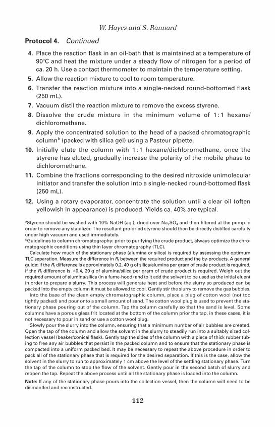
4. Place the reaction flask in an oil-bath that is maintained at a temperature of90�C and heat the mixture under a steady flow of nitrogen for a period ofca. 20 h. Use a contact thermometer to maintain the temperature setting.
5. Allow the reaction mixture to cool to room temperature.
6. Transfer the reaction mixture into a single-necked round-bottomed flask(250 mL).
7. Vacuum distil the reaction mixture to remove the excess styrene.
8. Dissolve the crude mixture in the minimum volume of 1 : 1 hexane/dichloromethane.
9. Apply the concentrated solution to the head of a packed chromatographiccolumnb (packed with silica gel) using a Pasteur pipette.
10. Initially elute the column with 1 : 1 hexane/dichloromethane, once thestyrene has eluted, gradually increase the polarity of the mobile phase todichloromethane.
11. Combine the fractions corresponding to the desired nitroxide unimolecularinitiator and transfer the solution into a single-necked round-bottomed flask(250 mL).
12. Using a rotary evaporator, concentrate the solution until a clear oil (oftenyellowish in appearance) is produced. Yields ca. 40% are typical.
aStyrene should be washed with 10% NaOH (aq.), dried over Na2SO4 and then filtered at the pump inorder to remove any stabilizer. The resultant pre-dried styrene should then be directly distilled carefullyunder high vacuum and used immediately.bGuidelines to column chromatography: prior to purifying the crude product, always optimize the chro-matographic conditions using thin layer chromatography (TLC).
Calculate how much of the stationary phase (alumina or silica) is required by assessing the optimumTLC separation. Measure the difference in Rf between the required product and the by-products. A generalguide: if the Rf difference is approximately 0.2, 40 g of silica/alumina per gram of crude product is required;if the Rf difference is �0.4, 20 g of alumina/silica per gram of crude product is required. Weigh out therequired amount of alumina/silica (in a fume-hood) and to it add the solvent to be used as the initial eluentin order to prepare a slurry. This process will generate heat and before the slurry so produced can bepacked into the empty column it must be allowed to cool. Gently stir the slurry to remove the gas bubbles.
Into the base of the clean empty chromatographic column, place a plug of cotton wool (not tootightly packed) and pour onto a small amount of sand. The cotton wool plug is used to prevent the sta-tionary phase pouring out of the column. Tap the column carefully so that the sand is level. Somecolumns have a porous glass frit located at the bottom of the column prior the tap, in these cases, it isnot necessary to pour in sand or use a cotton wool plug.
Slowly pour the slurry into the column, ensuring that a minimum number of air bubbles are created.Open the tap of the column and allow the solvent in the slurry to steadily run into a suitably sized col-lection vessel (beaker/conical flask). Gently tap the sides of the column with a piece of thick rubber tub-ing to free any air bubbles that persist in the packed column and to ensure that the stationary phase iscompacted into a uniform packed bed. It may be necessary to repeat the above procedure in order topack all of the stationary phase that is required for the desired separation. If this is the case, allow thesolvent in the slurry to run to approximately 1 cm above the level of the settling stationary phase. Turnthe tap of the column to stop the flow of the solvent. Gently pour in the second batch of slurry andreopen the tap. Repeat the above process until all the stationary phase is loaded into the column.
Note: If any of the stationary phase pours into the collection vessel, then the column will need to bedismantled and reconstructed.
W. Hayes and S. Rannard
112

Once all the stationary phase has been loaded into the column and has settled such that the bed iscompact, level, and stable (mark the side of the column with a marker pen to record the level of the sta-tionary phase as it settles), pour a small amount of sand carefully onto the head of the stationaryphase. This is used to prevent disruption of the top few centimetres of the stationary phase when freshmobile phase solvents are added to the column.
The column can now be used to purify the crude product. Allow the solvent level in the column todrop to just above (ca. 1 mm) the level of the stationary phase. Apply the crude mixture as a concen-trated solution in a solvent system that is less polar than the solvent system to be used as the initial col-umn mobile phase. Allow the level of the crude product solution to drop to the top of the stationaryphase, but do not allow the column to become dry.
Carefully pour in the first aliquot of mobile phase and allow that to run at a steady rate through thecolumn. Once the flow of solvent has started through the column, the separation must not be stopped
3: Controlled/‘living’ polymerization methods
113
Solvent
Sand
Sample
Silica/alumina gel
SandCotton wool/glass frit
Conical flask / test tube
Solventreservoir
Ground glass/Quick-fit joint
Compressedgas
Solvent flowcontroller
Fig. 3.3 Experimental set-up for flash column chromatography.

Protocol 4. Continueduntil all of the required products have been eluted. Never allow the column to run dry. Collect regular-sized fractions (use scintillation vials ca. 20 mL) and use TLC analysis to monitor the components elut-ing from the column.
For Flash column chromatography, the column preparation is analogous to that described above,however, the stationary phase material is of finer grade and requires pressure in order to force thesolvent through the column (Figure 3.3).
Protocol 5.
Bulk polymerization of styrene using a TEMPO-based unimolecular
initiator (Scheme 4)
Caution! Carry out all procedures in a well-ventilated fume-hood, wearappropriate disposable gloves, a lab-coat, and safety glasses. All vacuum-line work should be performed while standing behind a protective Perspexscreen.
Polystyrene possessing a degree of polymerization of 192 monomer units andMn � 20 300 has been targeted in the following procedure described by Hawkerand co-workers.22
Equipment● Dual manifold (nitrogen/vacuum) ● Schlenk flask (10 mL)● Vacuum source ● Three-way tap, gas-tight and equipped
with ground-glass joint● Source of dry nitrogen ● Rubber septa● Hotplate stirrer ● Beaker (1500 mL)● Teflon-coated magnetic stirrer bar ● Buchner filter● Contact thermocouple ● Buchner filter apparatus● 0.5 mL gas-tight syringe � 20 cm long narrow ● Filter paper (Whatman no. 1)
bore needle ● Oil-bath
Materials● Freshly distilled styrene,a 5.21 g, 50 mmol flammable, harmful by inhalation,
irritating to eyes and skin● TEMPO-based unimolecular initiator, 0.099 g, 0.26 mmol treat as toxic● THF for precipitation, ca. 20 mL irritant, highly flammable may form
explosive peroxides ● Methanol for precipitation, 2 � ca. 500 mL irritant, flammable
Method
1. To a clean, dry Schlenk flask (10 mL) that is maintained under positive nitro-gen pressure via the side-arm (that is equipped with an appropriate rubberseptum) (Figure 3.4), add the TEMPO-based unimolecular initiator (0.099 g,0.26 mmol).
2. Seal the Schlenk flask by attaching the three-way tap that is equipped with aground-glass joint. Use either high-quality vacuum grease or preferably,Teflon tape to create a vapour-tight seal on the flask. Redirect the nitrogen
W. Hayes and S. Rannard
114

purge by connecting the nitrogen inlet to the three-way tap and opening thevent on the side-arm of the Schlenk tube.
3. To the above mixture, add freshly distilled styrene (5.21 g, 50 mmol) directlyvia a gas-tight syringe through the side-arm of the Schlenk tube. Once theaddition is complete, seal the flask by closing the side-arm tap.
4. Degas the mixture by using repetitive freeze–pump–thaw cyclesb (repeat thecycle at least three times).
5. Seal the tube under a nitrogen atmosphere and then place it in an oil-baththat is maintained at a temperature of 123�C. Upon immersion in the hot oil-bath, the polymerization mixture will become homogeneous and willdevelop a yellowish-red colour.
6. The polymerization mixture will eventually solidify and at this point (typic-ally �24 h) the Schlenk flask should be removed from the hot oil-bath andallowed to cool to room temperature.
7. Dissolve the solid in the minimum volume of THF (�10 mL).
8. Precipitate the polystyrene by dropping the concentrated THF solution usingPasteur pipette into the vortex walls of a rapidly stirred ten-fold excess ofcold methanol (ca. 500 mL). Contain the methanol in a large beaker (1500 mL)to carry out this operation. A fine white precipitate should result.c
3: Controlled/‘living’ polymerization methods
115
Heat source
~110°C
N2
Schlenk tube
Contactthermometer
Rubberseptum
Stirrerbar
Vacuum
Three-waytap
Monomer+initiating system
Fig. 3.4 Experimental apparatus for bulk polymerization of styrene using TEMPO-basedunimolecular initiators.

Protocol 5. Continued
9. Filter the suspension and dry the white powder obtained in a vacuumoven (set to 50�C). Following drying, record the mass of polystyrene obtained.
10. Dissolve the polystyrene obtained in THF so as to obtain a viscous solutionand then repeat steps 8 and 9.
11. Analyse the product using GPC calibrated with a range of polystyrene nar-row standards to determine Mn andMw/Mn.
aSee Protocol 4.bFreeze–pump–thaw degassing is carried out as follows: (i) Ensure that the Schlenk flask has been thor-oughly purged with nitrogen. (ii) Freeze the solution by immersing the Schlenk flask in a bath of liquidnitrogen (care required when handling liquefied gases) that is contained in a nitrogen Dewar. (iii) Oncethe solution is completely frozen, keep the flask submerged in the liquid nitrogen and then apply highvacuum to it by rotating the three-way tap to the appropriate position. After a short period (typically1 min), seal the Schlenk flask by again rotating the three-way tap to the appropriate position. (iv) Remove the flask from the liquid nitrogen bath. Allow the contents of the flask to warm up to roomtemperature and the solution will melt (as this occurs, small gas bubbles will appear and dissipate intothe void above the surface of the solution). (v) Increase the nitrogen gas pressure (so as to avoid suckback) and then backfill the Schlenk tube with nitrogen by slowly rotating the three-way tap to theappropriate position. Repeat steps 2–5 at least three times.cIf an opaque white solution is obtained, the crude polystyrene solution is too dilute. Remove moreTHF from this solution using rotary evaporation and then re-continue the precipitation. Alternatively, ifwhite ‘string-like’ material results from the initial addition of the polymer solution to the methanol,then the crude polystyrene solution is too concentrated and will require dilution by the addition of THF.At the end of the addition of the crude polymer solution to the methanol, if a fine white dispersion thatcan be readily filtered has not been obtained, then simply remove all of the solvent by rotary evapora-tion and repeat the process, in this case adjusting the concentration of the crude polymer solution andthe volume of methanol used.
4. Controlled free-radical polymerizations: atom transfer free-radical polymerizations (ATRP) and aqueous ATRP
Atom transfer free-radical polymerization24 (ATRP) proceeds by a transient/stable radical mechanism analagous to nitroxide-mediated free-radicalpolymerizations (see Section 3). This controlled polymerization concept wasfirst described25,26 independently by two research groups in 1995, andexhibits a high degree of control over the molecular weight of the desiredpolymer and more remarkably, the ability to realize very narrow molecularweight distributions (Mw/Mn � 1.05). ATRP methodologies involve (seeScheme 6) the one-electron oxidation of a transition metal (‘MLn’ where ‘L’is a ligand) with concomitant abstraction of a halide atom from a stableorganic halide (the dormant species ‘RX’) to lead to the generation of ahighly reactive organic radical (the transient species ‘R•’). This organic rad-ical can freely propagate in the presence of monomer. Subsequent reductiveabstraction of the halide from the metal by the transient (propagating) radical‘P•’m�x leads to the generation of a dormant polymer ‘Pm�xX’.
W. Hayes and S. Rannard
116

Scheme 6 Simplified general mechanism for ATRP.
A wide variety of transition metals have been studied and, in addition,numerous ligand systems have also been investigated.24 Of those studied, thecopper(I)/copper(II) redox couple has proved to be the most popular trans-ition metal in combination with either 2,2�-bipyridine or 2-pyridinecarbalde-hyde imine27 ligand systems. ATRP has been shown to be a very versatilecontrolled polymerization system and compatible with a diverse set ofmonomers (styrene, methyl methacrylate, acrylates etc). The methodologyhas recently been adapted to allow the controlled room temperature polymer-ization of hydrophilic monomers in aqueous solvent,28–31 thus becoming thefirst ‘living’ polymerization to tolerate large amounts of water and allow awide range of water-soluble block copolymer syntheses. In addition, ATRPhas also enabled the synthesis of a wide range of hydrophilic and hydro-phobic polymer architectures that could not be realized via more conventionalpolymerization techniques.32,33
RX MLn R XMLn+ +
Monomer
Pm X MLn Pm XMLn+ +
Monomer
Pm+1 X MLn Pm+1 XMLn+ +
x (Monomer)
Propagation continues until [monomer]~0
Pm+x X MLn Pm+x XMLn+ +
Dormant Transient
3: Controlled/‘living’ polymerization methods
117

Protocol 6.
Bulk polymerization of styrene using ATRP
Caution! Carry out all procedures in a well-ventilated fume-hood, wear appro-priate disposable gloves, a lab-coat, and safety glasses. All vacuum-line workshould be performed while standing behind a protective Perspex screen.
Polystyrene possessing a degree of polymerization of 95 monomer units andMn � 10 000 has been targeted in the following bulk polymerization procedurereported by Matyjaszewski and co-workers24,26 (Scheme 7).
Scheme 7 Polymerization of styrene using ATRP.
Equipment● Dual manifold (nitrogen/vacuum) ● 0.5 mL gas-tight syringe � 20 cm long narrow bore needle● Vacuum source ● Short chromatographic column (ca. 15 cm long,
ca. 20 mm i.d.)● Source of dry nitrogen ● Scintillation vials (50 � 20 mL)● Hotplate stirrer ● Beaker (2 � 1500 mL)● Contact thermocouple ● Single-necked round-bottomed flask (250 mL)● Teflon-coated magnetic stirrer bar ● Buchner filter● Schlenk flask (10 mL) equipped ● Buchner filter apparatus
with side-arm and gas-tight tap● Three-way tap, gas-tight and equipped ● Filter paper (Whatman no. 1)
with ground-glass joint● Small rubber septa ● Oil-bath
Note: Use the same experimental set-up as described in Protocol 5.
Materials● Freshly distilled styrene,a 6.01 g, 57.7 mmol flammable, harmful by inhalation,
irritating to eyes and skin● Copper(I) bromide, 0.088 g, 0.61 mmol irritating to eyes, respiratory system, and skin● Benzyl bromide, 0.103 g, 0.60 mmol irritating to eyes, respiratory system, and skin● 2,2�-Bipyridine, 0.196 g, 1.26 mmol toxic by inhalation, in contact with skin, and
if swallowed, irritating to eyes,
respiratory system, and skin● THF for precipitation and alumina column, irritant, highly flammable may form
ca. 250 mL explosive peroxides● Neutral alumina, ca. 15 g harmful by inhalation, irritating to respiratory system● Methanol for precipitation, 2 � ca. 500 mL irritant, flammable
Method
1. To a clean, dry Schlenk flask (10 mL) that is maintained under positive nitro-gen pressure via the side-arm, add copper(I) bromide (0.088 g, 0.734 mmol),
Br
n
Br
110°CN
N Cu(I)Br+ +n 2
W. Hayes and S. Rannard
118

2,2�-bipyridine (0.196 g, 0.734 mmol) and benzyl bromide (0.103 g,0.734 mmol).
2. Seal the Schlenk flask by attaching the three-way tap that is equipped with aground-glass joint. Use either high-quality vacuum grease or preferably,Teflon tape to create a vapour-tight seal on the flask. Redirect the nitrogenpurge by connecting the nitrogen inlet to the three-way tap and opening thevent on the side-arm of the Schlenk tube.
3. To the above mixture, add freshly distilled styrene (6.01 g, 57.7 mmol)directly via a gas-tight syringe through the side-arm of the Schlenk tube.Once the addition is complete, seal the flask by closing the side-arm tap andequip it with an appropriate rubber septum.
4. Degas the mixture by using repetitive freeze–pump–thaw cyclesb (repeat thecycle at least three times).
5. Seal the tube under a nitrogen atmosphere and then place it in an oil-baththat is maintained at a temperature of 110�C. Upon immersion in the hot oil-bath, the polymerization mixture will become homogeneous and willdevelop a deep red/brown colour.
6. The polymerization mixture will eventually solidify and at this point (typ-ically 18–24 h) the Schlenk flask should be removed from the hot oil-bathand allowed to cool to room temperature.
7. Dissolve the solid in the minimum volume of THF (ca. 3–5 mL) and applythis concentrated solution to a short alumina columnc (ca. 15 cm long,�20 mm i.d. containing approximately 10 g alumina packed in THF). PassTHF through the column and collect an appropriate number of fractions (ca.5 mL fractions) until all of the polystyrene has eluted (using a short glasscapillary, place approximately 1 �L of each fraction onto a small silica TLCplate and visualize the plate under a UV lamp—if polystyrene is present, adark blue spot will be apparent).
8. Transfer all of the THF fractions that contain the polystyrene into a single-necked round-bottomed flask (ca. 100 mL) and concentrate the solutionusing a rotary evaporator until the viscosity of the solution increases (thevolume of the solution will be ca. 10 mL).
9. Precipitate the polystyrene by dropping the concentrated THF solution usingPasteur pipette into the vortex walls of a rapidly stirred ten-fold excess ofcold methanol (ca. 500 mL). Contain the methanol in a large beaker (1500 mL)to carry out this operation. A fine white precipitate should result.d
10. Filter the suspension and dry the white powder obtained in a vacuum oven(set to 50�C). Following drying, record the mass of polystyrene obtained.
11. Dissolve the polystyrene obtained in THF so as to obtain a viscous solutionand then repeat steps 9 and 10.
12. Once a constant weight is achieved, record the yield of the brilliant whitepowder.
3: Controlled/‘living’ polymerization methods
119

Protocol 6. Continued
13. Analyse the product using GPC calibrated with a range of polystyrene nar-row standards to determine Mn and Mw/Mn.
aSee Protocol 4.bSee Protocol 5.cSee Protocol 4.dSee Protocol 5.
Protocol 7.
Synthesis of the 2-bromoisobutyrate ester of poly(ethylene oxide)
(PEG-Br): an aqueous ATRP initiator
This method for the preparation of the PEG-Br initiator is based upon the proced-ure described by Wang and Armes34 (Scheme 8).
Scheme 8 Preparation of the PEG-Br.
Caution! Carry out all procedures in a well-ventilated fume-cupboard, wearappropriate disposable gloves, a lab-coat, and safety glasses. All vacuum-linework should be performed while standing behind a protective Perspex screen.Never use flat-bottomed flasks with rotary evaporators.
Equipment● Dean–Stark apparatus ● Glass stoppers● Vacuum source ● Beaker (500 mL)● Three-necked round-bottomed flask (500 mL) ● 5 mL gas-tight syringe � 10 cm narrow
bore needle● Hotplate stirrer ● Filter paper (Whatman no. 1)● Teflon-coated magnetic stirrer bar ● Buchner filter apparatus● Pressure-equalizing addition funnel (10 mL) ● Buchner funnel● Dry nitrogen source ● Water condensor● Rubber septa ● Oil-bath
Materials● Monomethoxy-capped poly(ethylene glycol) irritant, harmful if swallowed and by inhalation
Mn � 1100, 20.0 g, 18.3 mmol● Triethylamine, 4.7 mL, 36.7 mmol flammable, irritant, harmful by inhalation● 2-Bromoisobutyryl bromide corrosive, irritant, harmful by inhalation● Toluene, 250 mL irritant, flammable● Diethyl ether for precipitation, 2 � 250 mL irritant, highly flammable
Method
1. Add monomethoxy-capped poly(ethyleneglycol) (Mn � 1100, 20.0 g, 18.3 mmol)to a clean, dry three-necked flask (500 mL) under a positive pressure of dry
MeOO
OHn
+Br O
Br
PhMe / Et3NMeO
OO
n
O
Br
W. Hayes and S. Rannard
120

nitrogen. Transfer toluene (250 mL) to the flask and add the stirrer bar. Fit theDean and Stark apparatus and condenser to the flask and stopper the remainingnecks. Heat the mixture gently until a homogeneous solution has been formed.
2. Increase the temperature of the oil-bath until the solution begins to reflux.Collect the initial fraction in the Dean–Stark apparatus. This is the water/toluene azeotrope and removal of this fraction will ensure a dry toluenesolution of poly(ethylene glycol). Allow the solution to cool.
3. Whilst maintaining a positive pressure of dry nitrogen, remove the Dean–Stark apparatus and refit the condenser and nitrogen supply to the flask.Replace one stopper with a rubber septum and fit a pressure-equalizing addi-tion funnel (10 mL) to the other neck of the flask.
4. Using a gas-tight syringe (5 mL), add triethylamine (4.7 mL, 36.7 mmol) tothe room temperature solution and stir. Add 2-bromoisobutyryl bromide(4.54 mL, 36.7 mmol) to the addition funnel. Add the 2-bromisobutyryl brom-ide to the reaction dropwise, over 15 min, so that any exotherm is controlled.Stir the reaction at room temperature for a further 48 h whilst maintaininga positive pressure of dry nitrogen.
5. Filter the white precipitate using a Buchner filtration apparatus and discardthe precipitate. Concentrate the remaining clear solution to approximately50 mL using a rotary evaporator. Precipitate the product from the concentrateby drop-wise addition into the vortex walls of rapidly stirred cold diethylether (250 mL). Filter the white precipitate from the solvent using a Buchnerfiltration apparatus. Dissolve the precipitate in toluene (50 mL) and repeatthe precipitation process. Filter the white precipitate again and dry undervacuum to remove all traces of solvent. The final product should be storedunder dry nitrogen in the dark. Yields �90% are usual.
6. Analyse the PEG-Br product using 1H NMR, 13C NMR, and FT-IR spectro-scopies and MALDI-TOF mass spectrometry.35
Protocol 8.
Polymerization of oligo(ethylene glycol) methacrylate using
aqueous ATRP
This method for aqueous ATRP is based upon the procedure described by Wangand Armes34 (Scheme 9).Caution! Carry out all procedures in a well-ventilated fume-cupboard, wearappropriate disposable gloves, a lab-coat, and safety glasses. All vacuum-linework should be performed while standing behind a protective Perspex screen.
Poly(oligoethylene glycol methacrylate) possessing a degree of polymeriza-tion of 20 repeat units and a molecular weight Mn � 9000 has been targeted inthe following polymerization procedure.
3: Controlled/‘living’ polymerization methods
121

Protocol 8. Continued
Scheme 9 Polymerization of oligo(ethylene glycol) methacrylate using aqueous ATRP(RBr � PEG-Br).
Equipment● Two-necked round-bottomed flask (100 mL) ● Sintered-glass filter funnel (porosity 2)● Hotplate stirrer ● Teflon-coated magnetic stirrer bar● Dry nitrogen source ● Rubber septa● 10 cm narrow bore needle ● 2 cm narrow bore needle● Buchner filter apparatus ● 5 mL sample vial● Glass stopper ● Vacuum source
Materials● Oligo(ethylene glycol) methacrylate [average harmful, irritating to eyes and skin,
degree of polymerization � 7], 10 g, 23.8 mmol possible sensitizer● PEG-Br,a 0.5 g, 1.20 mmol treat as toxic● Copper(I) Bromide, 0.172 g, 1.20 mmol irritating to eyes, respiratory system, and skin● 2,2�-bipyridine, 0.375 g, 2.40 mmol harmful, irritating to eyes and skin, harmful● Deionized water, 5 mL non-toxic● Silica irritating to the respiratory system
Method
1. Add deionized water (5 mL), PEG-Br initiatora (0.5 g, 1.20 mmol), oligo(ethyl-ene glycol) methacrylate (10 g, 23.8 mmol) and magnetic stirrer bar to a100 mL two-necked round-bottomed flask. Fit a rubber septum to each neck.Place the small needle into one septum to act as a vent.
2. Attach the 10 cm needle to the end of a rubber tube joined to a dry nitrogensource. Place the needle into the second septum and bubble dry nitrogenthrough the solution for 30 min to remove all oxygen.
3. After degassing the solution, remove the needle from the solution but do notremove from the septum. Remove the small vent needle from the first septum.
4. Fill a sample vial (5 mL) with dry nitrogen and replace the cap. Weigh theCu(I)Br (0.172 g, 1.20 mmol) and 2,2�-bipyridine (0.375 g, 2.40 mmol) into thenitrogen-filled sample vial and replace cap.
5. Remove the first septum from the reaction flask while maintaining a positivepressure of dry nitrogen through the second septum. Empty the contents ofthe sample vial (Cu(I)Br/2,2�-bipyridine) into the flask, stopper the open neck
O
Me
O
O
Me m
OO
O
Me m
Me
n
OEGMA poly(OEGMA)
RBr/Cu(I)ClBipy/H2O
W. Hayes and S. Rannard
122

with a glass stopper, and stir at room temperature for 1 h under the drynitrogen pressure.
6. The reaction mixture will become dark brown indicating the predominantpresence of the Cu(I) species. An exotherm (5–10�C) may be noted. (Kineticdata have shown that �99% conversion of monomer is achieved within25 min.)
7. Add the sintered-glass funnel to the Buchner filter system and attach thevacuum source. Fill the funnel to a depth of 2 cm using anhydrous silica.Filter the aqueous polymer solution through the silica. A blue colour willappear, indicating the Cu(II) species that is formed in the presence of oxygen.The solution of polymer must be freeze-dried overnight to remove all waterand leave a white solid polymer product. Yields �90% are typical.
8. Analyse the polymer using GPC (THF using PMMA standards), 1H NMR, 13CNMR, and IR spectroscopies.
aSee Protocol 7.
The controlled polymerization techniques that have been described abovedo not, in general (with the exception of GTP), require exhaustive exclusionof moisture and purification of monomers and reagents. Several of the ‘liv-ing’ polymerization methods reported so far do suffer these experimentalrestrictions and, thus, uptake of these techniques by the polymer communityhas been limited. There are several notable examples of ‘living’ polymeriza-tions that merit recognition, including anionic methods,36 cationic polymer-izations,37 ‘immortal’ polymerizations mediated by metalloporphyrinreagents,38 reversible addition fragmentation chain transfer (RAFT)39 tech-niques and ring-opening metathesis polymerizations (ROMP).40 Each ofthese ‘living’ polymerization methods has its own beneficial attributes andmonomer compatibility characteristics and, therefore, careful considerationmust be taken when selecting a ‘living’ polymerization process.
References1. For an excellent description of the mechanism of chain-growth polymerization,
see: Odian, G. In Principles of Polymerization, 3rd edn., Wiley-Interscience:New York; 1991, Ch. 3.
2. (a) Szwarc, M.; Levy, M.; Milkovich, R. J. Am. Chem. Soc. 1956, 78, 2656.(b) Szwarc, M. J. Polym. Sci., Part A: Polym. Chem. 1998, 36, ix.
3. Flory, P. J. Principles of Polymer Chemistry; Cornell University Press: New York;1953.
4. Quirk, R. P.; Lee, B. Polym. Int. 1992, 27, 359.5. Webster, O. W. Science 1991, 251, 887.6. Sorenson, W. R.; Campbell, T. W. Preparative Methods of Polymer Chemistry,
2nd edn., Wiley-Interscience: New York; 1968, Ch. 4.
3: Controlled/‘living’ polymerization methods
123
7. Webster, O. W.; Hertler, W. R.; Sogah, D. Y.; Farnham, W. B.; Rajanbabu, T. V.J. Am. Chem. Soc. 1983, 105, 5706.
8. Sogah, D. Y.; Farnham, W. B. In Organosilicon and BioorganosiliconChemistry: Structure, Bonding, Reactivity and Synthetic Applications; Sakurai, H.,ed., John Wiley & Sons: New York; 1985, Ch. 20.
9. Farnham, W. B.; Sogah, D. Y. ACS Polym. Prepr. 1982, 27(1), 167.10. Quirk, R. P.; Bidinger, G. Polym. Bull. 1989, 22, 63.11. Webster, O. W. Makromol. Chem. Macromol. Symp. 1992, 60, 287.12. Jenkins, A. D. Eur. Polym. J. 1993, 29(2/3), 449.13. Dicker, I. B.; Farnham, W. B.; Hertler, W. R.; Laganis, E. D.; Sogah, D. Y.;
Del Pesco, T. W.; Fitzgerald, P. H. US Patent No. 4588795 1986.14. Dicker, I. B.; Cohen, G. M.; Farnham, W. B.; Hertler, W. R.; Laganis, E. D.;
Sogah, D. Y. Macromolecules 1990, 23, 4034.15. Ainsworth, C.; Chen, F.; Kuo, Y. H. J. Organomet. Chem. 1972, 46, 59.16. Eastmond, G. C.; Grigor, J. Makromol. Chem. Rapid Commun. 1986, 7, 37.17. Moad, G.; Rizzardo, E.; Solomon, D. H. Macromolecules, 1982, 15, 909.18. Georges, M. K.; Veregrin, R. P. N.; Kazmaier, P. M.; Hamer, G. K.
Macromolecules 1993, 26, 2987.19. Hawker, C. J. Acc. Chem. Res. 1997, 30, 373.20. Malmström, E. E.; Hawker, C. J. Macromol. Chem. Phys. 1998, 199, 923.21. Emrick, T.; Hayes, W.; Fréchet, J. M. J. J. Polym. Sci., Part A: Polym. Chem.
1999, 37, 3748.22. Hawker, C. J.; Barclay, G. C.; Dao, J. J. Am. Chem. Soc. 1996, 118, 11 467.23. Dao, J.; Benoit, D.; Hawker, C. J. J. Polym. Sci., Part A: Polym. Chem. 1998, 36,
2161.24. Patten, T. E.; Matyjaszewski, K. Acc. Chem. Res. 1999, 32, 895.25. Kato, M.; Kamigaito, M.; Sawamoto, M.; Higashimura, T. Macromolecules
1995, 28, 1721.26. Wang, J. S.; Matyjaszewski, K. J. Am. Chem. Soc. 1995, 117, 5614.27. Haddleton, D. M.; Jasieczek, C. B.; Hannon, M. J.; Shooter, A. J.
Macromolecules 1997, 30, 2190.28. Gaynor, S. G.; Qiu, J.; Matyjaszewski, K. Macromolecules 1998, 31, 5951.29. Ashford, E. J.; Naldi, V.; O’Dell, R.; Billingham, N. C.; Armes, S. P. J. Chem.
Soc., Chem. Commun. 1999, 1285.30. Wang, X. S.; Lascelles, S. F.; Jackson, R. A.; Armes, S. P. J. Chem. Soc., Chem.
Commun. 1999, 1817.31. Wang, X. S.; Malet, F. L. G.; Armes, S. P.; Haddleton, D. M.; Perrier, S. M.
Macromolecules 2001, 34, 162.32. Grubbs, R. B.; Hawker, C. J.; Dao, J.; Fréchet J. M. J. Angew. Chem., Int. Ed.
Engl. 1997, 36, 270.33. Leduc, M. R.; Hayes, W.; Fréchet J. M. J. J. Polym. Sci., Part A: Polym. Chem.
1998, 36, 1.34. Wang, X.-S.; Armes, S. P. Macromolecules 2000, 33, 6640.35. Yu, D.; Vladimirov, N.; J. M. J. Fréchet, J. M. J. Macromolecules 1999,
32, 5186.36. Fontanille, M. In Comprehensive Polymer Science; Pergammon Press: Oxford;
1989, Vol. 3, Ch. 25, p. 365.
W. Hayes and S. Rannard
124

37. Miyamoto, M.; Sawamoto, M.; Higashimura, T. Macromolecules 1984, 17, 265.38. Inoue, S.; Aida, T.; Kuroki, M.; Hosokawa, Y. Makromol. Chem. Macromol.
Symp. 1992, 32, 255.39. Chiefari, J.; Chong, Y. K.; Ercole, F.; Krstina, K.; Jeffrey, J.; Le, T. P. T.;
Mayadunne, R. T. A.; Meijs, G. F.; Moad, C. L.; Moad, G.; Rizzardo, E.; Thang, S. H. Macromolecules 1998, 31, 5559.
40. Grubbs, R. H.; Gilliom, L. R. J. Am. Chem. Soc. 1986, 108, 733.
3: Controlled/‘living’ polymerization methods
125