controlled environment solutions
TRANSCRIPT

Controlled environment solutionsProduct datasheet
At a glance:
Self supporti ng internal structuresSingle spanning capabilityPrecision jointi ng detailIndustry leading airti ghtnessExcellent thermal U values up to 0.10 W/m2KUp to 60-minute fi re resistanceFood safe and hygienic steel coati ngs

Rev: 0620-A
Hemsec Controlled Environment Solutions Pg: 1 / 10
Applications Hemsec steel faced polyisocyanurate insulated sandwich panels for controlled environments, utilised in applications such as:
Food processing and preparation Blast and Spiral freezers Fruit ripening rooms Storage and warehousing Distribution centres Retail solutions and dual compartment rooms Internal fire rated builds including fire walls Spray booths Drying rooms Data centres Clean rooms Pharmaceutical and laboratory environments Internal column cladding
Typically designed for specific internal operating temperatures and conditions which usually range between +30°C and -40 °C.
About Hemsec Hemsec have quietly and diligently become one of the largest manufacturers of composite insulated panels in the UK. We work in partnership across the supply chain and are trusted by companies who need absolute confidence in the timely delivery of high quality, durable building materials.
Everything we manufacture, either keeps cold air inside a structure, or firmly shuts it out.
Our aim is, and always has been, to create trusted partnerships with our customers, and to supply them with the best quality insulated panels in the world, keeping excellent delivery times. As a consequence of doing this, we remain responsible, and make a positive impact in the world.
Core values of Quality, Responsibility, Trust, and Partnerships influence our organisation at every level meaning every person involved in the manufacturing of our panels, takes great pride in their work.
Rev: 0620-A
Pg: 2 / 10
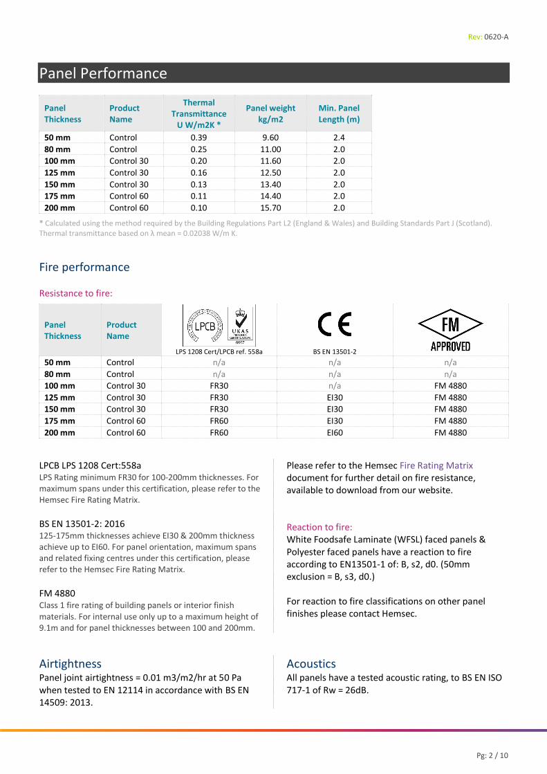
Panel Performance
Panel Thickness
Product Name
Thermal Transmittance
U W/m2K *
Panel weight kg/m2
Min. Panel Length (m)
50 mm Control 0.39 9.60 2.4 80 mm Control 0.25 11.00 2.0 100 mm Control 30 0.20 11.60 2.0 125 mm Control 30 0.16 12.50 2.0 150 mm Control 30 0.13 13.40 2.0 175 mm Control 60 0.11 14.40 2.0 200 mm Control 60 0.10 15.70 2.0
* Calculated using the method required by the Building Regulations Part L2 (England & Wales) and Building Standards Part J (Scotland). Thermal transmittance based on λ mean = 0.02038 W/m K.
Fire performance Resistance to fire:
Panel Thickness
Product Name
LPS 1208 Cert/LPCB ref. 558a
BS EN 13501-2
50 mm Control n/a n/a n/a 80 mm Control n/a n/a n/a 100 mm Control 30 FR30 n/a FM 4880 125 mm Control 30 FR30 EI30 FM 4880 150 mm Control 30 FR30 EI30 FM 4880 175 mm Control 60 FR60 EI30 FM 4880 200 mm Control 60 FR60 EI60 FM 4880
LPCB LPS 1208 Cert:558a LPS Rating minimum FR30 for 100-200mm thicknesses. For maximum spans under this certification, please refer to the Hemsec Fire Rating Matrix. BS EN 13501-2: 2016 125-175mm thicknesses achieve EI30 & 200mm thickness achieve up to EI60. For panel orientation, maximum spans and related fixing centres under this certification, please refer to the Hemsec Fire Rating Matrix. FM 4880 Class 1 fire rating of building panels or interior finish materials. For internal use only up to a maximum height of 9.1m and for panel thicknesses between 100 and 200mm.
Please refer to the Hemsec Fire Rating Matrix document for further detail on fire resistance, available to download from our website. Reaction to fire: White Foodsafe Laminate (WFSL) faced panels & Polyester faced panels have a reaction to fire according to EN13501-1 of: B, s2, d0. (50mm exclusion = B, s3, d0.) For reaction to fire classifications on other panel finishes please contact Hemsec.
Airtightness Panel joint airtightness = 0.01 m3/m2/hr at 50 Pa when tested to EN 12114 in accordance with BS EN 14509: 2013.
Acoustics All panels have a tested acoustic rating, to BS EN ISO 717-1 of Rw = 26dB.
Rev: 0620-A
Hemsec Controlled Environment Solutions Pg: 3 / 10
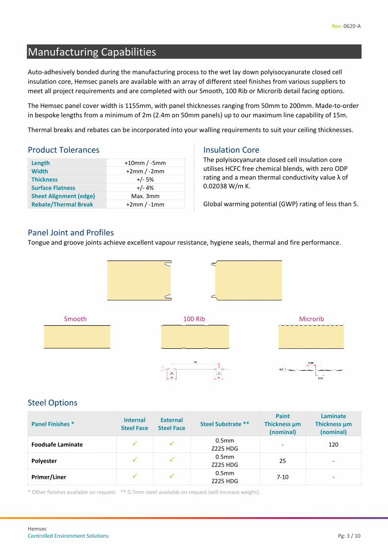
Manufacturing Capabilities Auto-adhesively bonded during the manufacturing process to the wet lay down polyisocyanurate closed cell insulation core, Hemsec panels are available with an array of different steel finishes from various suppliers to meet all project requirements and are completed with our Smooth, 100 Rib or Microrib detail facing options.
The Hemsec panel cover width is 1155mm, with panel thicknesses ranging from 50mm to 200mm. Made-to-order in bespoke lengths from a minimum of 2m (2.4m on 50mm panels) up to our maximum line capability of 15m.
Thermal breaks and rebates can be incorporated into your walling requirements to suit your ceiling thicknesses.
Panel Joint and Profiles Tongue and groove joints achieve excellent vapour resistance, hygiene seals, thermal and fire performance.
Smooth 100 Rib Microrib
Steel Options
Panel Finishes * Internal Steel Face
External Steel Face Steel Substrate **
Paint Thickness µm
(nominal)
Laminate Thickness µm
(nominal)
Foodsafe Laminate 0.5mm
Z225 HDG - 120
Polyester 0.5mm
Z225 HDG 25 -
Primer/Liner 0.5mm
Z225 HDG 7-10 -
* Other finishes available on request. ** 0.7mm steel available on request (will increase weight).
Product Tolerances
Length +10mm / -5mm Width +2mm / -2mm Thickness +/- 5% Surface Flatness +/- 4% Sheet Alignment (edge) Max. 3mm Rebate/Thermal Break +2mm / -1mm
Insulation Core The polyisocyanurate closed cell insulation core utilises HCFC free chemical blends, with zero ODP rating and a mean thermal conductivity value λ of 0.02038 W/m K.
Global warming potential (GWP) rating of less than 5.

Rev: 0620-A
Pg: 4 / 10
Rebates & Thermal Breaks
Maximum 200mm rebate positioned at the top of the panel to suit ceiling panel thicknesses (a). Landing depths of 40mm for 80mm wall panels or 50mm for 100 - 200mm wall panels (b). 50mm wall panels cannot be rebated. 20mm saw cut depth, thermal break (c). Positioned between 80 - 300mm from base of panel (d).
Quality & Durability Hemsec steel faced panels are made from the highest and most robust quality materials, on a state-of-the-art continuous production line within the UK.
Our company is BS EN ISO 9001:2015 certified, quantifying our quality management system and demonstrating our ability to consistently provide products and services that meet customer and regulatory requirements.
Further to this, we operate within our Quality Plan to strict Factory Production Control (FPC) measures, defining documentation and Quality Control Procedures which ensure our conformity with CE marking to BS EN 14509:2013.
Guarantee Here at Hemsec we are so confident in the quality of our panels that we offer an industry leading guarantee of up to 40 years on metal faced panels (limited only by the guarantee on the steel facings).
Panel guarantee covering the following:
25-year thermal performance; 25-year Hemsec panel performance; 15-year internal coating guarantee, subject to
project specific information. Up to 40-year external coating guarantee,
subject to project specific information. Please contact Hemsec for more information on our
Environmental Hemsec recognise our responsibilities in working towards a sustainable future and demonstrate excellent performance in minimising the environmental impact of our manufacturing processes. Maximising the environmental benefits of our products contributes to the well-being of the communities we operate and conduct our business within, in the most economically viable manner.
Energy consumption within buildings which utilise our Insulated panel systems is reduced over much of the buildings life due to the long lifespan of our products, which typically exceeds 40 years.
A guide outlining the options for end-of-life procedures of insulated panels whether for reuse, recycling or waste disposal has been developed by EPIC (Engineered Panels in Construction). Available from www.epic.uk.com
For further information, our Metal Faced Sustainability Statement is available to download from our website.
a b
d
c

Rev: 0620-A
Hemsec Controlled Environment Solutions Pg: 5 / 10
Structural Data Internal Ceilings The below information and span table are for the design of insulated ceiling panels that are classified as "ceilings accessible for installation, occasional inspection and maintenance, minor repairs and cleaning" only.
The load / span tables are designed for concentrated loads of 0.9kN, 1.2kN or 1.5kN.
Under CDM legislation there is a requirement to appoint a Principal Designer, who is responsible for the full design and all the safety aspects related to safety during construction and thereafter enclosure operation. The Principal Designer is also responsible for the production of the building manual and the safety of operatives during maintenance and access activities.
In respect of access and maintenance it is the responsibility of the Principal Designer to post notices, that limits loads applied to a ceiling and the time those loads are applied. If necessary, upon the principal designer’s advice a signed permit system may operate for access and maintenance.
Spans are based on a dead load plus imposed load, giving a total combined (dead & imposed) of 0.25kN/m2. It is the principal designer responsibility to confirm the maximum permitted imposed loads including UDL and point loads during construction and the maximum loads permitted for access and maintenance when the enclosure is complete in operation. Details of permitted imposed loads must be incorporated into any Operating and Maintenance manual (O&M). The designer should decide the loadings based on the panel capacity details provided by Hemsec.
The ability of the panel to resist the imposed load, is dependent on the end support connection i.e. support bearing width, number of fasteners used and the support thickness, as well as the type of fastener. The allowable steelwork tolerance between bearing planes of adjacent supports is +/- 5mm.
Hemsec strongly recommend referring to our Metal Faced Ceiling Care Instructions for greater detail, available to download from our website. The maximum ceiling spans are governed by a uniformly distributed service load. In the absence of any specified imposed loads, a conservative recommendation would be that the ceiling panels and associated structural elements are designed for a concentrated load of 0.9kN and a uniformly distributed service load of 0.25kN/m2.

Rev: 0620-A
Pg: 6 / 10
Internal Ceiling Span Table: The spans identified in the below table are separated by the following temperature differences:
Δ18 or Delta 18, includes ambient and chill applications which are typically above 0°C (where the difference between the internal and external temperatures is no more than 18⁰C – i.e. +1⁰C to +19⁰C).
Δ50 or Delta 50, includes freezer applications which are typically below 0°C (where the difference between the internal and external temperatures is no more than 50⁰C – i.e. -40⁰C to +10⁰C).
Please utilise the span provided for your temperature controlled applications: For fire rated projects: Please refer to the Hemsec Fire Rating Matrix and reference the maximum spans under the certification body you require.
Span (m) based on L/200
Panel Thickness
Product Name
Load 0.9 kN point + 0.25kN kg/m2 UDL
Load 1.2 kN point + 0.25 kN/m2 UDL
Load 1.5 kN point + 0.25 kN/m2 UDL
Δ18 (chill)
Δ50 (freeze)
Δ18 (chill)
Δ50 (freeze)
Δ18 (chill)
Δ50 (freeze)
50 mm Control 3.73 3.30 3.30 3.30 2.93 2.93 80 mm Control 5.77 5.30 5.30 5.30 4.89 4.89 100 mm Control 30 6.94 6.63 6.44 6.45 6.00 6.00 125 mm Control 30 8.24 8.30 7.71 7.23 7.23 7.22 150 mm Control 30 9.54 9.51 8.96 8.96 8.45 8.45 175 mm Control 60 10.71 10.70 10.13 10.13 9.60 9.60 200 mm Control 60 11.87 11.87 11.28 11.28 10.74 10.74
Table Notes: The assumptions below have been made in the calculation of the above span table and designers should ensure that these assumptions are valid for their project requirements. If different loading parameters (deflection, loads and temperatures) are appropriate for the project, please contact Hemsec.
1. Spans are based on BS EN 14509:2013 (supported by ECCS Document 115 Part 1: 2001 and BS EN 1991-1-1:2002). 2. The UDL is the combination of the dead load plus imposed load giving a combined load of 0.25kN/m2. 3. Spans allow for a single point load mid span of the panel. 4. Spans are from mid-points of the supporting walls. 5. The load / span tables apply to short-term imposed loads on simply supported panels (supported at each end of the panel)
generally used for ceilings. 6. Calculations are only for ceilings without apertures. 7. Maximum deflection: Short-term is L/200 and long-term is L/100. 8. Load span tables are unfactored and based on 0.5mm nominally thick metal internal and 0.5mm nominally thick metal external
facings. 9. All panel thicknesses have been calculated with a minimum bearing/support width of 100mm. Consult Hemsec for further
information on permitted bearing loads and edge supports.
Rev: 0620-A
Hemsec Controlled Environment Solutions Pg: 7 / 10
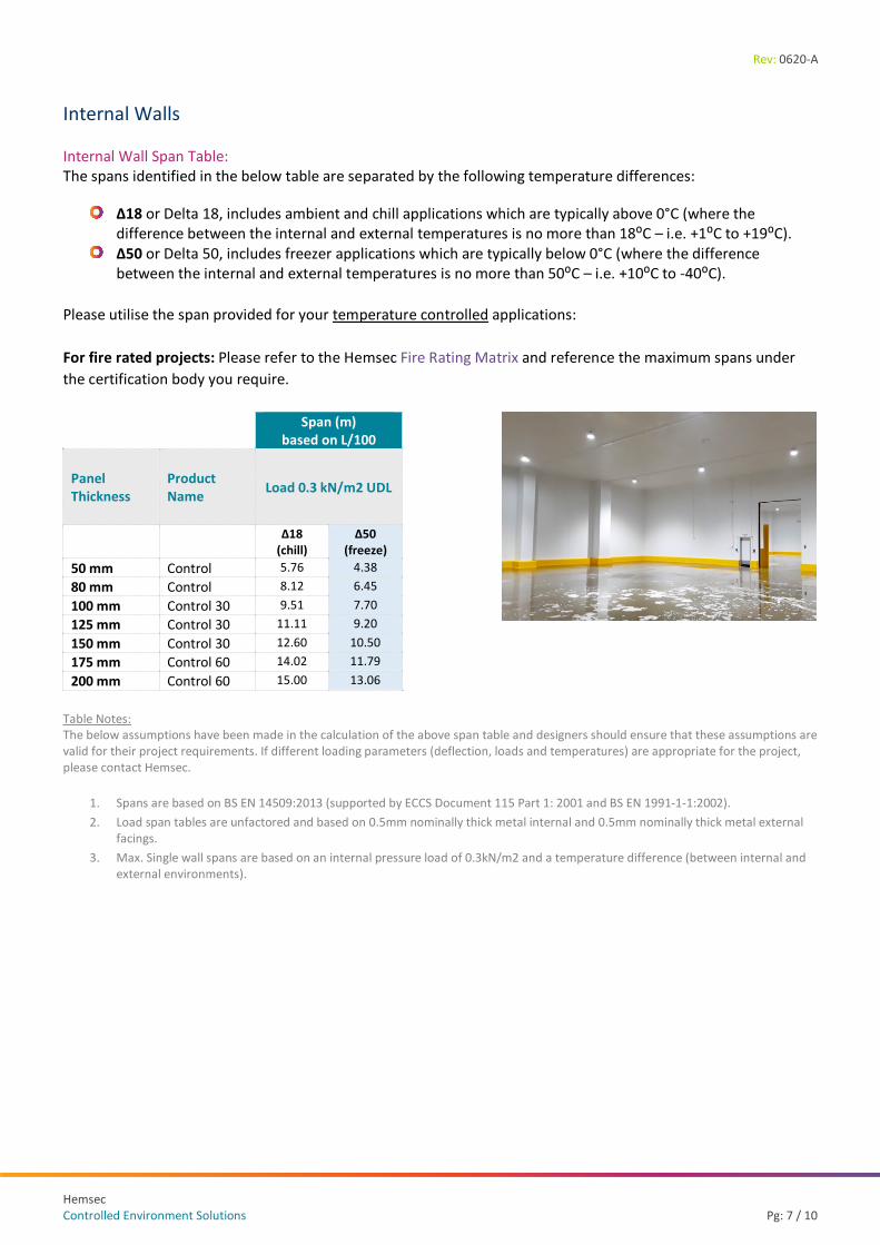
Internal Walls Internal Wall Span Table: The spans identified in the below table are separated by the following temperature differences:
Δ18 or Delta 18, includes ambient and chill applications which are typically above 0°C (where the difference between the internal and external temperatures is no more than 18⁰C – i.e. +1⁰C to +19⁰C).
Δ50 or Delta 50, includes freezer applications which are typically below 0°C (where the difference between the internal and external temperatures is no more than 50⁰C – i.e. +10⁰C to -40⁰C).
Please utilise the span provided for your temperature controlled applications: For fire rated projects: Please refer to the Hemsec Fire Rating Matrix and reference the maximum spans under the certification body you require.
Span (m) based on L/100
Panel Thickness
Product Name Load 0.3 kN/m2 UDL
Δ18 (chill)
Δ50 (freeze)
50 mm Control 5.76 4.38 80 mm Control 8.12 6.45 100 mm Control 30 9.51 7.70 125 mm Control 30 11.11 9.20 150 mm Control 30 12.60 10.50 175 mm Control 60 14.02 11.79 200 mm Control 60 15.00 13.06
Table Notes: The below assumptions have been made in the calculation of the above span table and designers should ensure that these assumptions are valid for their project requirements. If different loading parameters (deflection, loads and temperatures) are appropriate for the project, please contact Hemsec.
1. Spans are based on BS EN 14509:2013 (supported by ECCS Document 115 Part 1: 2001 and BS EN 1991-1-1:2002). 2. Load span tables are unfactored and based on 0.5mm nominally thick metal internal and 0.5mm nominally thick metal external
facings. 3. Max. Single wall spans are based on an internal pressure load of 0.3kN/m2 and a temperature difference (between internal and
external environments).

Rev: 0620-A
Pg: 8 / 10
Delivery & Site Procedures All deliveries are made by road transport to the project site, subsequent offloading and storage is the responsibility of the customer. Please refer to the Hemsec Metal Faced Panel Care Instructions document for further detail, available to download from our website, and are attached to each pack of delivered panels.
Packaging Hemsec steel faced insulated sandwich panels are stacked horizontally with protective jiffy foam laid between the ends of each panel; they are then wrapped in polythene and strapped on top of a 3mm hardboard sheet to prevent forklift damage and to protect against the weather. The pack is supported by a number of polystyrene bearers, (150mm x 100mm), regularly spaced under the hardboard to keep the panels elevated from the floor avoiding dirt and possible damage.
The number of panels in each pack depends on panel length and weight. Typical pack height is 1100mm.
Panel Thickness 50mm 80mm 100mm 125mm 150mm 175mm 200mm No. panels/pack (max) 10 10 9 7 6 5 4
Maximum pack weight is 1000kg. Each pack is labeled with project information and customer panel references.
Traceability We make our panels traceable via a date print on the panel joint and each pack contains a label stating the product name and details on included panels.
Indicative Detail Drawings Our drawings should be considered indicative only, as Hemsec do not underwrite project design. Please visit our website for the latest Controlled Environment Detail Drawings set which can also be supplied in both PDF and DWG formats, on request from Hemsec.
Please also refer to the IACSC Design Guide for Temperature Controlled Environments, an industry standard installation guide providing details and advice.
Flashings and Ancillaries Flashings can be manufactured to match all your technical specifications, with the same steel coil to match any panels ordered from Hemsec. Various designs are available, folded to a maximum length of 3000mm, inclusive of safety folds where required (excluding galvanised and five-bar aluminium). Hemsec can also source a range of stock ancillary items suitable for various applications. Please contact Hemsec for further information.
Channels
External Angles
Internal Angles
Cover Strips
Various Sheets
Rev: 0620-A
Hemsec Controlled Environment Solutions Pg: 9 / 10
Advice & Guidance Definitions Δ18 / Δ50 Δ18 or Delta 18, includes ambient and chill applications which are typically above 0°C (where the difference between the internal and external temperatures is no more than 18⁰C – i.e. +1⁰C to +19⁰C). Δ50 or Delta 50, includes freezer applications which are typically below 0°C (where the difference between the internal and external temperatures is no more than 50⁰C – i.e. +10⁰C to -40⁰C). The position of the temperature difference on the above continuums make no difference to the panel spans provided, but, the absolute difference might.
Airtightness Airtightness primarily focuses on the elimination of all unintended gaps and cracks, an essential part of creating a healthy, comfortable, energy-efficient environment. The greater the airtightness at a given pressure difference across the envelope, the lower the infiltration. Air permeability is the physical property used to measure the airtightness of the building fabric and is defined as air leakage rate per hour per square metre of envelope area.
CDM legislation Construction (Design and Management) Regulations. This is a set of health and safety regulations that apply to every construction project in Great Britain.
Concentrated load (or point load) The load that acts as a point on the ceiling over an area of 125mm x 125mm, such as the action of walking on the upper surface of the ceiling panels by the full weight of a person plus any carried items.
Dead load Loads that are relatively constant over time, including the weight of the structure itself, and immovable fixtures. Also known as permanent or static loads.
Deflection The degree to which a structural element is displaced under a load (bending or sag caused by loading). It may refer to an angle or a distance. Allowable deflection is generally expressed as a fraction of the span.
Extended field of application A report defined by a notified body in order to extend the coverage of existing fire test evidence contained within one or more fire test reports which were conducted to the BS EN series of standards in order for a Classification Report to be written for CE marking purposes.
Factory production control (FPC) Factory Production Control (FPC) covers the procedures which are put in place to allow a manufacturer to maintain consistency in quality and to keep records of non-conforming products, processes or materials, in order to make improvements. The need for FPC comes as a result of the requirement for CE marking, which is needed to satisfy the essential requirements of the Construction Products Directive.
Imposed load The load assumed to be produced by the intended occupancy or use, are usually temporary, changeable and dynamic including distributed and concentrated loads but excluding wind loads. May involve impact, vibration or acceleration. Also known as live loads.
Reaction to fire An expression of a material’s behaviour (under the Euroclass System to EN13501-1). A reaction-to-fire test assesses how easily a product can be ignited and contribute to a fire growth. It relates mostly to the early stages of fire development and is arguably mostly relevant to products directly exposed to the fire source. Building products are tested for reaction to fire and divided into seven Euroclasses (A1, A2, B, C, D, E & F). Further classifications are used to indicate smoke production (s1, s2 & s3), and burning droplets (d0, d1 & d2).
Resistance to fire The ability of a structural element to sustain the performance of its structural duty, whilst being exposed to the temperatures likely to be encountered in a developed fire for specified periods of time. It is a measure of its ability to withstand the effects of fire including resistance to collapse (maintain loadbearing capacity), resistance to fire penetration (maintain the integrity of the element) and resistance to excessive heat transfer (provide insulation from high temperatures).
Thermal transmittance (U value) Thermal transmittance, also known as U-value, is the rate of transfer of heat through a structure (single material or a composite), divided by the difference in temperature across that structure. Thermal performance is measured in terms of heat loss, U-values measure how effective a material is an insulator and the better insulated a structure is, the lower the U-value will be.
Uniformly Distributed Load (UDL) A uniformly distributed service load per square metre (kN/m2), distributed or spread across the whole region of an element, providing for situations such as the stacking of materials used during maintenance.

Rev: 0620-A
Pg: 10 / 10
Guides / Associations CEBA – Controlled Environment Building Association Publishers of the design guide for Temperature Controlled Environments (IACSC). Find experienced designers, contractors, manufacturers and suppliers for your next project. www.gcca.org/ceba
EPIC – Engineered Panels in Construction Publishers of the Insulated Panels Identification and Disposal guide. Not-for-profit trade association representing the PIR rigid urethane insulated panel industry in the UK. www.epic.uk.com
MPBA – Modular and Portable Building Association Playing a key role in connecting all sectors of the modular and portable building industry together. www.mpba.biz
LPCB – Loss Prevention Certification Board Working with industry and insurers to set the standards needed to ensure that fire and security products and services perform effectively. Part of BRE Global. www.redbooklive.com
CE Marking How a product complies with EU safety, health and environmental requirements. www.gov.uk/guidance/ce-marking
FM Global When you have higher loss protection product testing and certification standards, you’ll prevent more losses. That’s the philosophy behind FM Approvals. www.fmglobal.com
BASF The world leader in isocyanates, key components for producing rigid foam insulation. www.basf.com/gb
Made in Britain Celebrating the diversity of British manufacturing and promoting creativity, high standards and sustainable growth to the world. www.madeinbritain.org

www.hemsec.com
Hemsec Manufacturing LtdStoney Lane
RainhillPrescot
MerseysideL35 9LL
Tel: 0151 426 7171Email: [email protected]