controlled differential forced convection heating for glass tempering processes
TRANSCRIPT
ELSEVIER Journal of Non-Crystalline Solids 218 (1997) 235-241
] O U R H A L O F
Controlled differential forced convection heating for glass tempering processes
Kenneth R. Kormanyos *
Glasstech, Inc., Perrysburg, OH, USA
Abstract
A forced convection heater (FCH) based tempering system capable of heating glass loads 2.13 m by 3.66 m was developed and successfully demonstrated. Performance of the system was verified through processing glasses ranging in thickness from 2.3 mm to 19 mm. The heat transfer generated by the convective flow of the heated working fluid (hot air) can be adjusted by changing the impingement velocity of the fluid, the temperature of the fluid, or both. The controls are independent of each other so a large flow with lower temperature air or a small flow with higher temperature air can be set on the heating fluids of the top and bottom of the ceramic roller bed. The independence of control allows the heater to be tuned so glasses with a variety of colors or surface treatments can be processed effectively. © 1997 Elsevier Science B.V.
I. Introduct ion
Heating glass sheets to tempering temperatures for the safety glass industry is typical ly accom- plished in electric radiation roller hearth furnaces [1-3]. These conventional systems employ radiation heat transfer to the glass top surface and a combina- tion of radiation and conduction heat transfer to the bottom surfaces in contact with the rollers in the furnaces. Top-to-bot tom thermal imbalance due to differential total heat transfer causes mechanical warping of the glass sheets during the heating pro- cess [4,2]. Heater temperatures are normally set higher on the top to attempt a balance of total heat transfer since the glass top surface does not have the conduction heat transfer component added by the contact of the glass with the rollers. The traditional techniques have proven adequate for the production of clear glass tempered articles [4,2], but the method
* Tel.: + 1-419 661 9500; fax: + 1-419 666 5751.
is not responsive to variations in glass processing rates, tempered product color variations, or surface treatments.
The use of high performance reflective coatings on the surface of glass is becoming increasingly important to the end users of tempered glass prod- ucts. The products are referred to as low-E glasses; a glass sheet with one surface treated to have a low emissivity coating to reflect infrared heat. The needs of the end users are being met by the float glass manufacturers in the form of pyrolytic films applied as part of their process and by the glass tempering groups in the form of post processing film applica- tions. The infrared reflective qualities of the coatings cause additional thermal warping and increased heat- ing process time in radiation heated tempering sys- tems.
The glass tempering industry has evolved several methods to address the problems of heating low-E glasses [5-7]. Typical practice for heating the f i lmed glasses is to decrease the heater temperature set
0022-3093/97/$17.00 © 1997 Elsevier Science B.V. All rights reserved. Pll S0022-3093(97)00279-2
236 K.R. Korman yos / Journal of Non-Crystalline Solids 218 (1997) 235-241
points, increase the heating time of the process, attempt to increase the differential upper-to-lower radiation heater temperature set points, and introduce small streams of cold compressed air to generate a small level of convective flow on the surface of the glass [5-7]. These practices are counterproductive to the goals of maximizing process throughput and maintenance of product optical quality.
(a)
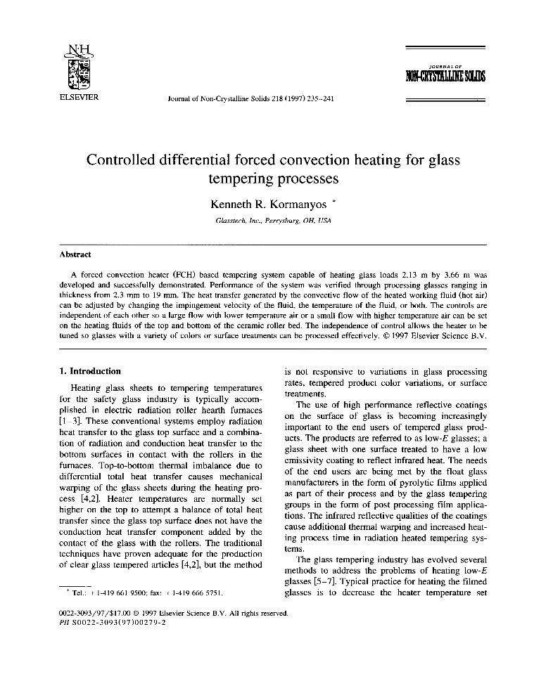
Properly controlled forced convective heat trans- fer can be tuned to balance the heating rates on the top and bottom glass surfaces. Convective heat trans- fer tuning capability coupled with sufficient avail- able heating power from natural gas burners have been combined in the FCH system to yield a well controlled high productivity glass heating technol- ogy.
CONTROLLED CONVECTIVE FLOW I OF HEATED AIR I
4. 4. 4. 4. 4. A 4. 4, 4. 4. 4. 4.
IBURIN
. . . . . . . :. . . . . . . . : . . . . . . . . :.:
ERI
i | |
RETURI~ OF SPENT AIR """ ~ I FOR RE-HEATING
o .,"" _. S°
o - ' ' " *o . . . . . . ' *
(b)
Fig. 1. Forced convection heated (FCH) tempering system used for the flat glass tempering demonstrations. The glass loading conveyor is shown at the lower right of the figure; product flow is toward the upper left through the FCH heater. (a) Sketch of a lower section of the FCH showing approximate distribution and return flows of the heated air working fluid.
K.R. Kormanyos / Journal of Non-Crystalline Solids 218 (1997) 235-241 237
2. Experimental
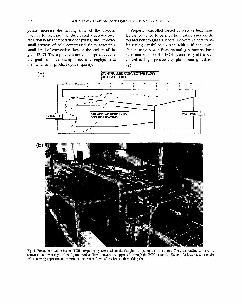
A natural gas fired forced convection heater (FCH) was designed and fabricated to heat glass for flat glass tempering demonstrations. Figs. 1 and 2 show the production sized FCH demonstration system and its internal active heater area. Fig. 1 a shows a sketch of the lower FCH heater section with approximate flows described for both the controlled convective heated working fluid flow and return of the spent working fluid for re-heating. The FCH system was designed to meet the physical requirements of uni- formly heating glass sheets to their required tempera- ture through the application of a well controlled flow of heated working fluid (hot air) to the surfaces of the in-process glass. The fluid's temperature in the recirculating system is maintained by a single control loop feed-back system in each heater zone which monitors the working fluid temperature in the system and adds hot combustion products from the burner as required to maintain the fluid's set point temperature. The system recirculates its working fluid volume approximately one time per second in each of the multiple control zones providing fast response to temperature changes as the glass is heated.
Surface decorations on tempered glass products continue to be requested by the glass end users which when combined with the reflective surface coatings make the heating process more difficult. Patterned decorations on the top surface of glass to be heated cause variations in top surface heating rates to occur because the decorated regions absorb a greater amount of radiant heat than do the undeco- rated regions. The variations in top surface heating result in mechanical warping of the glass sheet dur- ing the initial stages of heating. The forced convec- tion heating process overcomes the variation in top surface heating since the major mode of heat transfer is controlled by the uniform application of a heated working fluid stream to the glass surface.
3. Results
3.1. Glass tempering studies
Glass surface coating variations and glass body color variations were successfully processed to ac- ceptable temper levels for 1.1 m X 1.1 m X 6 mm samples including: clear, gray, bronze, reflective
Fig. 2. Internal view of the FCH roller hearth.
238 K.R. Kormanyos /Journal of Non-Crystalline Solids 218 (1997) 235-241
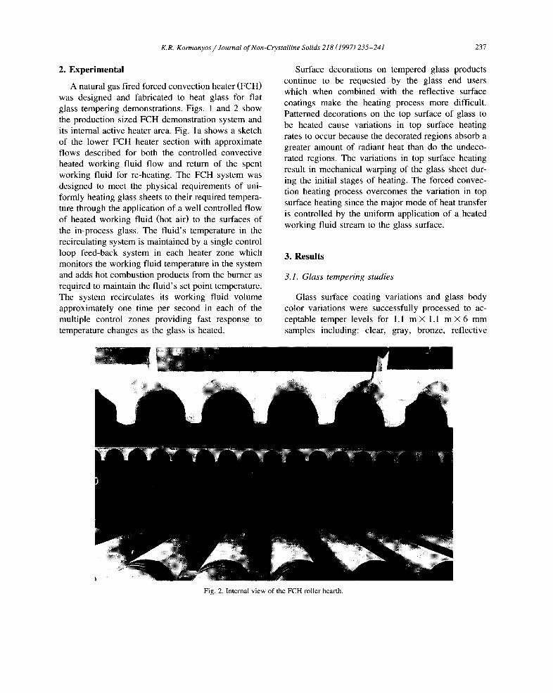
bronze and clear low-E. The FCH heater was mea- sured to heat the glass to the ~ 625°C temperature in about 160 s at a set point of 650°C. Fig. 3 shows the results of heating trials at heater set points of 630, 650 and 670°C for clear glass. All of the 6 mm glass samples regardless of color or surface coating were processed at a 160 s heating time with resulting exit temperatures of 620-625°C. The heating time was ~ 67% of the time required by a typical radia- tion heater [8,9].
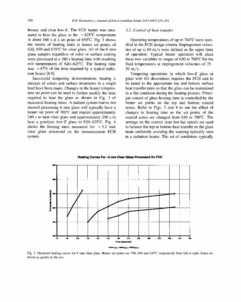
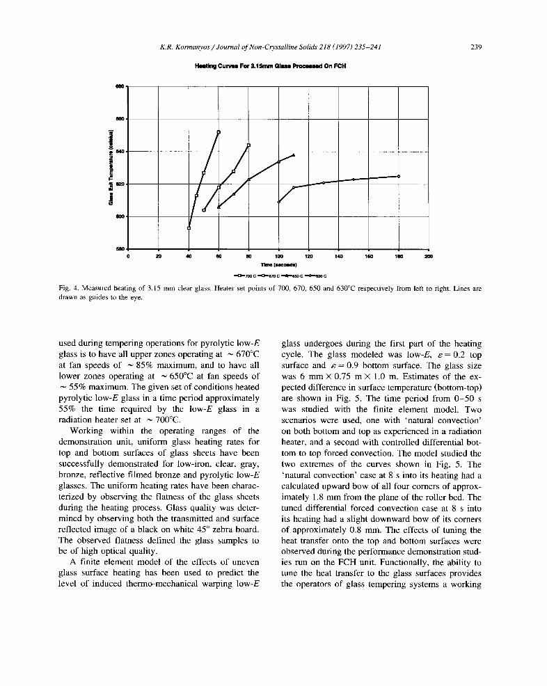
Successful tempering demonstrations heating a mixture of colors and surface treatments in a single load have been made. Changes in the heater tempera- ture set point can be used to further modify the time required to heat the glass as shown in Fig. 3 of measured heating times. A radiant system (curve not shown) processing 6 mm glass will typically have a heater set point of 700°C and require approximately 240 s to heat clear glass and approximately 290 s to heat a pyrolytic low-E glass to 620-625°C. Fig. 4 shows the heating rates measured for ~ 3.2 mm clear glass processed on the demonstration FCH system.
3.2. Control of heat transfer
Operating temperatures of up to 760°C were spec- ified in the FCH design criteria. Impingement veloci- ties of up to 60 m / s were defined as the upper limit of operation. Typical heater operation will place these two variables in ranges of 630 to 700°C for the fluid temperatures at impingement velocities of 2 5 - 50 m / s .
Tempering operations in which low-E glass or glass with frit decorations requires the FCH unit to be tuned to the appropriate top and bottom surface heat transfer rates so that the glass can be maintained in a flat condition during the heating process. Princi- pal control of glass heating time is controlled by the heater set points on the top and bottom control zones. Refer to Figs. 3 and 4 to see the effect of changes in heating time as the set points of the control zones are changed from 630 to 700°C. The settings on the control zone hot fan speeds are used to balance the top to bottom heat transfer so the glass heats uniformly avoiding the warping typically seen in a radiation heater. The set of conditions typically
Heating Curves For -6 mm Clear Glass Processed On FCH
/ /
f _ _ _ _ _ _
m
8807O g0 "110 130 180 170 1gO 210 23O 2S0 ~ 2gO 310
Time (seconds)
==0.=7ao c ~o-.~=o c . . ~ c
Fig. 3. Measured heating curves for 6 mm clear glass. Heater set points are 700, 650 and 630°C respectively from left to right. Lines are drawn as guides to the eye.
68o
K.R. Kormanyos /Journal of Non-Crystalline Solids 218 (1997) 235-241
Heat ing C u r v m For 3 . 1 5 m m G l m m Processed On FCH
239
J i / X ! j
/ / / f _
58O 0 20 40 60 80 100 120 140 160 180 200
Time ( ~ o n d s )
• -(3--7o0 C ..,43--67o C . -~, -65o C ,-(1~63o C
Fig. 4. Measured heating of 3.15 mm clear glass. Heater set points of 700, 670, 650 and 630°C respectively from left to right. Lines are drawn as guides to the eye.
used during tempering operations for pyrolytic low-E glass is to have all upper zones operating at ~ 670°C at fan speeds of ~ 85% maximum, and to have all lower zones operating at ~ 650°C at fan speeds of
55% maximum. The given set of conditions heated pyrolytic low-E glass in a time period approximately 55% the time required by the low-E glass in a radiation heater set at ~ 700°C.
Working within the operating ranges of the demonstration unit, uniform glass heating rates for top and bottom surfaces of glass sheets have been successfully demonstrated for low-iron, clear, gray, bronze, reflective f i lmed bronze and pyrolytic low-E glasses. The uniform heating rates have been charac- terized by observing the flatness of the glass sheets during the heating process. Glass quality was deter- mined by observing both the transmitted and surface reflected image of a black on white 45 ° zebra board. The observed flatness defined the glass samples to be of high optical quality.
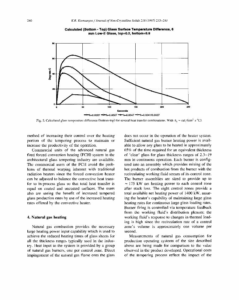
A finite element model of the effects of uneven glass surface heating has been used to predict the level of induced thermo-mechanical warping low-E
glass undergoes during the first part of the heating cycle. The glass modeled was low-E, e = 0.2 top surface and e = 0.9 bottom surface. The glass size was 6 mm X 0.75 m X 1.0 m. Estimates of the ex- pected difference in surface temperature (bottom-top) are shown in Fig. 5. The time period from 0 - 5 0 s was studied with the finite element model. Two scenarios were used, one with 'natural convection' on both bottom and top as experienced in a radiation heater, and a second with controlled differential bot- tom to top forced convection. The model studied the two extremes of the curves shown in Fig. 5. The 'natural convect ion ' case at 8 s into its heating had a calculated upward bow of all four comers of approx- imately 1.8 mm from the plane of the roller bed. The tuned differential forced convection case at 8 s into its heating had a slight downward bow of its corners of approximately 0.8 mm. The effects of tuning the heat transfer onto the top and bottom surfaces were observed during the performance demonstration stud- ies run on the FCH unit. Functionally, the ability to tune the heat transfer to the glass surfaces provides the operators of glass tempering systems a working
240 K.R. Kormanyos / Journal of Non-Crystalline Solids 218 (1997) 235-241
Calculated (Bottom - Top) Glass Surface Temperature Difference, 6 mm Low-E Glass, top=0.2, bottom=0.9
"1
20.
0 0 SO I SO I SO 200 250
Seconds
" ¢ ~ h = 0 . 0 0 0 7 " I : ~ h = 0 . 0 0 2 7 " ~ " h - - 0 . 0 0 4 7 " ¢ D h = 0 . 0 0 4 1 / 0 . 0 0 2 7
Fig. 5. Calculated glass temperature difference (bottom-top) for several heat transfer combinations. With h c ~ cal/(cm 2 s °C).
method of increasing their control over the heating portion of the tempering process to maintain or increase the productivity of the operation.
Commercial units of the advanced natural gas fired forced convection heating (FCH) system in the architectural glass tempering industry are available. The commercial users of the FCH avoid the prob- lems of thermal warping inherent with traditional radiation heaters since the forced convection heater can be adjusted to balance the convective heat trans- fer to in-process glass so that total heat transfer is equal on coated and uncoated surfaces. The users also are seeing the benefit of increased tempered glass production rates by use of the increased heating rates offered by the convective heater.
4. Natural gas heating
Natural gas combustion provides the necessary large heating power input capability which is used to achieve the reduced heating times of glass sheets for all the thickness ranges typically used in the indus- try. Heat input to the system is provided by a group of natural gas burners, one per control zone. Direct impingement of the natural gas flame onto the glass
does not occur in the operation of the heater system. Sufficient natural gas burner heating power is avail- able to allow any glass to be heated in approximately 65% of the time required for an equivalent thickness of 'clear' glass for glass thickness ranges of 2.3-19 mm in continuous operation. Each burner is config- ured into an assembly which provides mixing of the hot products of combustion from the burner with the recirculating working fluid stream of its control zone. The burner assemblies are sized to provide up to
175 kW net heating power to each control zone after stack loss. The eight control zones provide a total available net heating power of 1400 kW, assur- ing the heater's capability of maintaining large glass heating rates for continuous large glass loading rates. Burner firing is controlled via temperature feedback from the working fluid's distribution plenum; the working fluid's response to changes in thermal load- ing is high since the recirculation rate of a control zone's volume is approximately one volume per second.
Measurements of natural gas consumption for production operating systems of the size described above are being made for comparison to the value observed in the product developed. Operational costs of the tempering process reflect the impact of the
K.R. Korrnanyos / Journal of Non-C~. stalline Solids 218 (1997) 235-241 241
differences normally seen between the cost of deliv- ered energy for electric versus natural gas sources [8,9]. Depending upon the relative costs, an operat- ing FCH unit will cost approximately 0.3 to 0.5 as much per hour as an electric radiant heater [8,9]. The cost savings when combined with the increased glass production rates due to faster heating provide a significant increase in overall process productivity.
tional radiation heater. The FCH tempering system is in production at two commercial sites.
Acknowledgements
Glasstech expresses its thanks to the Gas Re- search Institute for their financial support in the co-funding of the development of the FCH concept.
5. Conclusions
Controlled differential forced convection heating (FCH) is a method of providing the tempering indus- try a tool with which difficult to heat glass products can be more efficiently processed. A controlled dif- ferential forced convection heating system powered with natural gas burners has been assembled and demonstrated as a viable glass heating device. Glass samples of several colors, surface coatings, and thickness variations have been successfully pro- cessed on the FCH unit. The use of the FCH reduces the heating time required for a given piece of clear glass to ~ 66% the time required by a conventional radiation heater. Pyrolytic low-E glass is processed in ~ 55% of the time normally required in a conven-
References
[ 1 ] What you should know about electrically heated furnaces used in glass tempering systems, US Glass, Metal&Glazing (May/June 1984) 77.
[2] Flat glass tempering-how it works, Glass Ind. (June 10, 1989) 10.
[3] How glass tempering practices affect product quality, Glass Ind. (June 1984) 14
[4] Glass annealing and tempering, The Handbook of Glass Man- ufacture, 3rd Ed., vol. II, Sept. 1984, pp. 832-2-832-13.
[5] J. Vitkala, Glass Technol. Int. I 5 (4) (1994) 79. [6] C. Morin, Glass Technol. Int. (Jan. 1996) 126. [7] J. Vitkala, R. Karvinen, Tampere University of Technology,
How to temper low-E glass, Tamglass Engineering Oy, Glass Production Technol. Int. (1996) 157.
[8] G. Abecassis, Verre 2 (5) (1996) 17. [9] R. Meheux, Verre F1 (4) (1995) 12.