control valve - polna corp val… · · 2012-05-21– during temporary period the flanges may be...
TRANSCRIPT

CONTROL VALVE
www.polnacorp.com
SERIES BR11®
version 09/2011

2
control valve series BR11®
Nominal dimension• DN 15 - DN 250
• 1/2” - 10”
Nominal pressure• PN 10 - 40
• Class 150, Class 300
Construction• single seat valve with balanced plug option
• metal or soft seat
Working temperature range• -180°C ... +400°C
Flow characteristic, Kvs value• linear, equipercentage or on/off
• 0,01 - 630 [m3/h]
Tightness class (IEC 60534 - 4)• class IV - standard, metal seat
• class V - optional for metal seat
• class VI - optional with soft seat
Body material• grey cast iron, ductile iron, carbon steel, stainless steel
according to EN, DIN or ASTM
Plug and seat material• stainless steel
• stellit or plasma nitridation possibility
End connection• flange
Actuators• pneumatic with diaphragm
• electro-hydraulic
• electric
• hydraulic
• manual operated
BR 11 - DiRect contRol valve

3
control valve series BR11®
USe
Single-ported globe control valves type BR11 are used in automatic and remote control systems to control flow of gases and liquids. Wide range of material and design versions make the valves widely sought-after in chemical industry, heat and power generation industry, pa-per industry, food industry, metallurgy and coal mining, etc.
cHaRacteRiStic
• Range of nominal sizes from DN15 to DN250 for pressures up to PN50 (ANSI300).• Wide range of flow ratios and control characteristics.• High level of valve tightness due to use of soft seal (with PTFE seal) in whole range of flow and control characteristic for balanced and
unbalanced plug.• Identical flow ratio and control characteristic for “hard” seats (metal-to-metal) and “soft” seats (metal-PTFE), for balanced and
unbalanced plug.• High durability and reliability due to application of top-class materials and surface treatment processes (burnishing, stelliting, heat
treatment, CrN coatings).• Reliable actuator-stem and valve seat-body connection.• Reduced acting force due to use of balanced plug for valves DN 40 to DN 250.• Top class flat seals and bonnet packings.• Assembly with pneumatic actuator, series P/R with reverse operation and possibility of spring range change - without need of any
additional parts (keeping the number of springs).• Possibility of special designs: – for Oxygen – for liquid or gas fuels – for low temperature media (liquid Oxygen, Nitrogen etc.).• Competitive prices – due to simple and functional design of valves and actuators and applied materials.
BR 11® – Product trademark registered at the Patent Office.
DeSiGn anD tecHnical SPeciFication
Valve body (1) – flanged, single-ported, casting in cast iron or cast steel.
Nominal sizes: DN15; 20; 25; 32; 40; 50; 65; 80; 100; 150; 200; 250
Nominal pressure and connection depends on material design:
– according to EN 1092-1; EN 1092-2; ANSI B16.5
– During temporary period the flanges may be made according to ISO 7005-1
Table 1.
Material Pressure
connection
Raised face Groove Recess Ring joint
identification
Grey Cast Iron PN10; 16B – – –
Ductile Iron PN10; 16; 25; 40
Cast Steel
PN10; 16; 25; 40 B D F –
PN20 *)
B1– –
JPN50 *) D1 F1
*) Connection marking according to ISO 7005-1
Body length: according to EN 60534-3-1; 2000y. – fig. 7; table 13 and 14.
Bonnet (2) – bonnet body - rolled steel connected to valve body by assembling plate (fig. 1.a)
– cast (fig. 1.b)
• standard
• extended
• bellows

4
control valve series BR11®
Valve Plug (3) contoured, balanced or unbalanced • control characteristic: – linear (L) – equipercentage (P) – quick opening (S) • rangeability: – 50:1
Standardowa Mieszkowa
DN15…50 DN65…100
Standardowa MieszkowaStandard Extension Bellow seal
Fig. 1. Bonnets DN15...100
TA LUFT packing (all types)
Standardowa MieszkowaStandard Extension Bellow seal

5
control valve series BR11®
Valve seat (4) – screwed, with centering cone and sealing. With unscrewing locking:
• hard
• soft (with PTFE sealing), see table 4
Stem (5) - burnished or quenched and tempered, polished sealing contact surface.
Drain plug (6) – steel or stainless steel: allows cleaning of body interior (delivered on request).
Body gasket (7) – asbestos-free, see table 2:
• flat – aramid and hardened graphite (1.4571); in metallic casing (1.4571), multiple edges
• bonnet: – packing formed from various materials (PTFE-V; PTFE+graphite; expanded graphite; braided graphite)
– with TA Luft compression springs (PTFE-V; graphite)
Table 2 – Packing types and application ranges.
Packing type Pn
temperature °c
Bonnet type
Standard extended Bellows
PVTFE-V
10 ... 50
-46 ... +200 -198 ... -46+200 ... +300 -100 ... +200PVTFE + Graphite
PVTFE-V / TA-LUFT
Graphite+200 ... +300 +300 ... +450 +200 ... +400
Graphite / TA-LUFT
Leakage class: • basic: class IV according to IEC 60534-4 – hard seat
• bubble-tight: class VI according to IEC 60534-4 – soft seat
Rys. 2. Rodzaje grzybów
Kvs 0,01…1DN15…50
Kvs 0,01…1 (DM/DW)Kvs 1,6…16DN15…50
Kvs 25…160DN40…100
Kvs 63…630DN150…250
Kvs 25…160DN40…100
Kvs 250…630DN150…250
Fig. 2. Valve plugs
Balanced valve plugs
Unbalanced valve plugs

6
control valve series BR11®
Table 3. Component list with material specification.
item Part name Material
1 Body EN-GJL 250 (EN-JL 1040)
EN-GJS 400-18 LT (EN-JS 1025)
GP 240 GH (1.0619) WCB GX5CrNiMo 19-11-2
(1.4408) CF8M
2 BonnetDN15...100 S 355 J2G3 (1.0570) X6CrNiMoTi 17-12-2 (1.4571)
DN15...250 EN-GJL 250 (EN-JL 1040)
EN-GJS 400-18 LT (EN-JS 1025)
GP 240 GH (1.0619) WCB GX5CrNiMo 19-11-2
(1.4408) CF8M
3 PlugX6CrNiMoTi 17-12-2 (1.4571)
X6CrNiMoTi 17-12-2 (1.4571) + stellit + CrN X17CrNi 16-2; (1.4057) + heat treatment
4 Seat
X6CrNiMoTi 17-12-2 (1.4571) X6CrNiMoTi 17-12-2 (1.4571) + stellit X6CrNiMoTi 17-12-2 (1.4571) + PTFE
X17CrNi 16-2; (1.4057) + heat treatment
5 StemX6CrNiMoTi 17-12-2 (1.4571)
X6CrNiMoTi 17-12-2 (1.4571) + stellit + CrN X17CrNi 16-2; (1.4057) + heat treatment
6 Drain plug S 355 J2G3 (1.0570) X6CrNiMoTi 17-12-2 (1.4571)
7 Body gasket With metal housing X6CrNoMoTi 17-12-2 (1.4571); NOVATEC PREMIUM; SIGRAFLEX HOCHDRUCK; NWK-50 SPETOMET
8 Guiding sleeveX6CrNiMoTi 17-12-2 (1.4571)
X6CrNiMoTi 17-12-2 (1.4571) + stellit + CrN X17CrNi 16-2; (1.4057) + heat treatment
9 Compression plate C45 (1.0503); X30Cr13 (1.4028); X6CrNiMoTi 17-12-2 (1.4571)
10 Bolt 8.8 A4 - 70
11 Nut 8 A4 - 70
12 Packing PTFE + GRAPHITE; PTFE - “V”; GRAPHITE
13 Spring 12R10 (SANDVIK)
14 „O“ ring Fluorine rubber (FKM)
15 Guiding sleeveX6CrNiMoTi 17-12-2 (1.4571)
X6CrNiMoTi 17-12-2 (1.4571) + stellit + CrN X17CrNi 16-2; (1.4057) + heat treatment
16 Seal ring KEFLOY 25
17 Bellow X6CrNiMoTi 17-12-2 (1.4571)
Material norms
Material Norm nr.
EN-GJL 250; (EN-JL 1040) EN 1561
EN-GJS 400-18 LT; (EN-JS 1025) EN 1563
GP 240 GH; (1.0619) EN 10213-2
G20Mn5, (1.6220) EN 10213-3
WCB ASTM A 216
GX5CrNiMo 19-11-2; (1.4408) EN10213-4
CF8M ASTM A 351
S 355 J2G3 (1.0570) EN 10025
P355 NL2; (1.1106) EN 10028-3
X6CrNiMoTi 17-12-2 (1.4571) EN 10088
X17CrNi 16-2; (1.4057) EN 10088
C45; (1.0503) EN 10083-1
X30Cr13; (1.4028) EN 10088
Note:Hardening method used for hardening of valve internal parts comprises:
a) stelliting – padding of surfaces with stellite: ~40HRC
b) CrN coating – introducing chromium nitride to external layer of detail, to the depth of ca.0.1 mm;~950HV
c) heat treatment: plug (~45HRC), seat (~35HRC), stem (~35HRC), guide sleeve (~45HRC)
d) max operating temperature -200..+250°C (for material KEFLOY 25), higher temperatures should be discussed with manufacturer.
Material normsMaterial norms
Max working pressure [Mpa]Min. Max.
with balanced plug -50+200
4
with soft seat (PTPE) -100 3,5
with bellows bonnet -100 +400 3,5
Table 4. Operation parameters for special design valves

7
control valve series BR11®
a) with standard valve plug b) with balanced plug
Fig. 3. Control valve DN15-100
a) with standard valve plug b) with balanced plug
Fig. 4. Control valve DN15-100
8
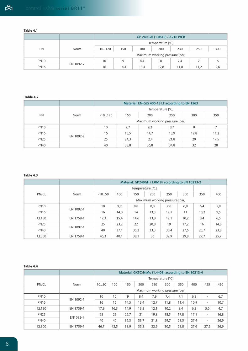
control valve series BR11®
GP 240 GH (1.0619) / a216 WcB
PN Norm
Temperature [°C]
-10...120 150 180 200 230 250 300
Maximum working pressure [bar]
PN10EN 1092-2
10 9 8,4 8 7,4 7 6
PN16 16 14,4 13,4 12,8 11,8 11,2 9,6
Table 4.1
Material: en-GJS 400-18 lt according to en 1563
PN Norm
Temperature [°C]
-10...120 150 200 250 300 350
Maximum working pressure [bar]
PN10
EN 1092-2
10 9,7 9,2 8,7 8 7
PN16 16 15,5 14,7 13,9 12,8 11,2
PN25 25 24,3 23 21,8 20 17,5
PN40 40 38,8 36,8 34,8 32 28
Table 4.2
Material: GX5crniMo (1.4408) according to en 10213-4
PN/CL Norm
Temperature [°C]
10...50 100 150 200 250 300 350 400 425 450
Maximum working pressure [bar]
PN10EN 1092-1
10 10 9 8,4 7,9 7,4 7,1 6,8 - 6,7
PN16 16 16 14,5 13,4 12,7 11,8 11,4 10,9 - 10,7
CL150 EN 1759-1 17,9 16,3 14,9 13,5 12,1 10,2 8,4 6,5 5,6 4,7
PN25EN1092-1
25 25 22,7 21 19,8 18,5 17,8 17,1 - 16,8
PN40 40 40 36,3 33,7 31,8 29,7 28,5 27,4 - 26,9
CL300 EN 1759-1 46,7 42,5 38,9 35,3 32,9 30,5 28,8 27,6 27,2 26,9
Table 4.4
Table 4.3
Material: GP240GH (1.0619) according to en 10213-2
PN/CL Norm
Temperature [°C]
-10...50 100 150 200 250 300 350 400
Maximum working pressure [bar]
PN10EN 1092-1
10 9,2 8,8 8,3 7,6 6,9 6,4 5,9
PN16 16 14,8 14 13,3 12,1 11 10,2 9,5
CL150 EN 1759-1 17,3 15,4 14,6 13,8 12,1 10,2 8,4 6,5
PN25EN 1092-1
25 23,2 22 20,8 19 17,2 16 14,8
PN40 40 37,1 35,2 33,3 30,4 27,6 25,7 23,8
CL300 EN 1759-1 45,3 40,1 38,1 36 32,9 29,8 27,7 25,7

9
control valve series BR11®
Material: G20Mn5 (1.6220) according to en 10213-3
PN Norm
Temperature [°C]
-40 100 150 200 250 300
Maximum working pressure [bar]
PN10
-
6 6 3,8 3,6 3,48 3,4
PN16 16 16 10,1 9,6 9,28 9,07
PN25 25 25 15,8 15 14,5 14,2
PN40 40 28 28 27 26 25
Table 4.5
Material: WcB according to aStM a216
PN/CL Norm
Temperature [°C]
-10...50 100 150 200 250 300 350 375 400
Maximum working pressure [bar]
PN10EN 1092-1
10 10 9,7 9,4 9 8,3 7,9 7,7 6,7
PN16 16 16 15,6 15,1 14,4 13,4 12,8 12,4 10,8
CL150 EN 1759-1 19,3 17,7 15,8 14 12,1 10,2 8,4 7,4 6,5
PN25EN1092-1
25 25 24,4 23,7 22,5 20,9 20 19,4 16,9
PN40 40 40 39,1 37,9 36 33,5 31,9 31,1 27
CL300 EN 1759-1 50 46,4 45,1 43,9 41,8 38,9 36,9 36,6 34,6
Table 4.6
Material: cF8M according to aStM a351
PN/CL Norm
Temperature [°C]
-10...50 100 150 200 250 300 350 375 400 425 450
Maximum working pressure [bar]
PN10EN 1092-1
8,9 7,8 7,1 6,6 6,1 5,8 5,6 5,5 5,4 5,4 5,3
PN16 14,3 12,5 11,4 10,6 9,8 9,3 9 8,8 8,7 8,6 8,5
CL150 EN 1759-1 18,4 16 14,8 13,6 12 10,2 8,4 7,4 6,5 5,6 4,6
PN25EN1092-1
22,3 19,5 17,8 16,5 15,5 14,6 14,1 13,8 13,6 13,5 13,4
PN40 35,6 31,3 28,5 26,4 24,7 23,4 22,6 22,1 21,8 21,6 21,4
CL300 EN 1759-1 48,1 42,3 38,6 35,8 33,5 31,6 30,4 29,6 29,3 29 29
Table 4.7

10
control valve series BR11®
Table 5. Flow ratio Kvs [m3/h] – for unbalanced plugs
Kvs[m3/h]
Stroke[mm]
Seatdiam.
a [cm3]
FD [kn] nominal valve size Dn characteristic
Hard seat
Soft seat 15 20 25 32 40 50 65 80 100 150 200 250 l P S
0,010
20
6,35 0,3 0,1 0,16
0,016
0,025
0,040
0,063
0,10
0,16
0,25
0,40
0,63
1,0
1,6 9,52 0,7 0,15 0,25
2,512,70 1,3 0,2 0,3
4,0
6,3 19,05 2,9 0,3 0,5
10 20,64 3,3 0,35 0,5
16 25,25 5,0 0,4 0,6
25 31,72 7,9 0,5 0,8
40 41,25 13,4 0,7 1,0
63
38
50,80 20,3 0,8 1,3
94 66,70 34,9 1,1 1,7
12588,90 62,1 1,4 2,2
160
25050
107,92 91,5 1,7 2,7
320 126,95 126,6 2,0 3,2
50063
158,72 197,9 2,5 4,0
630 195,00 198,6 3,1 4,9
Calculated ratios: FL=0,9; XT=0,72; Fd=0,46; xFz=0,65
Table 5. Flow ratio Kvs [m3/h] – for balanced plugs
Kvs[m3/h]
Stroke[mm]
nominal valve size Dn characteristic
40 50 65 80 100 150 200 250 l P S
2520
40
63
3894
125
160
25050
320
50063
630
Note:Valve seat diameter for balanced valve plug flow ratio Kvs 250 is 126.95 mm.

11
control valve series BR11®
Dia
gram
1: E
quip
erce
ntag
e flo
w c
hara
cter
isti
c of
con
trol
val
ves
Kvs=
0,25
...63
0 m
3 /h
9

12
control valve series BR11®
alloWeD PReSSURe DRoP Δp.
Pressure drops Δp [MPa] are valid for closed valve and are calculated related to actuator parameters. Real pressure drops should not ex-ceed 70% of allowable working pressures for given nominal pressure, material design and working temperature according to tables 4.1 to 4.7.
where: Δp [MPa] – calculated pressure drop
Fs [kN] – actuator available force (tab. 7)
FD [kN] – valve plug to valve seat pressure (tab. 5)
A – seat area ratio for seat with diameter D [cm2];
D – valve seat diameter [mm] (tab. 5)
Table 7. Available force Fs [kN] of pneumatic actuators
10 (Fs - FD)Δp = A
πD2
A = [cm2] 400
Note:1. For direct actuators P adopted spring range is 20 – 100 kPa.
2. For electric and other actuators Δp value can be calculated using above formula, available actuator force taken from the actuator datasheet.
3. For balanced valve plugs available force Fs at least equal to FD value for soft valve seats in Table 5 should be adopted.
actuator size
Direct function actuator - P Reverse function actuator - R
Supply pressure [kPa] Spring range [kPa]
140 250 400 20 - 100 40 - 120; 40 - 200 60 - 140 80 - 240 120 - 280 180 - 380
160 0,64 2,4 4,8 0,32 0,64 0,96 1,28 1,92 -
250 1,0 3,8 7,5 0,5 1,0 1,5 2,0 3,0 -
400 1,6 6,0 12,0 0,8 1,6 2,4 3,2 4,8 -
630 2,5 9,5 18,9 1,3 2,5 3,8 5,0 7,6 11,3
1000 4,0 15,0 30,0 2,0 4,0 6,0 8,0 12,0 18,0

13
control valve series BR11®
Table 8. Allowable pressure drops ∆p [bar] for valves with unbalanced plugs and hard seats, with pneumatic actuators.
Flow ratioKvs
[m3/h]
nominalvalve size
DnStroke[mm]
control pressure increase – air to close control pressure increase – air to open
actuator Δp [MPa] actuator
Δp [bar]Size
Spring range [kPa]
Supply pressure [kPa]Size
Spring range [kPa]140 250 400
do 4 15; 20; 25; 32; 40; 50
20
160
20 - 100
34 - -
160
20 - 100 40 - 200
9 34
6,3 20; 25; 32; 40; 50 11 40 -
20 - 100 40 - 200 60 - 140
7 11 23
10 25; 32; 40; 50 9 40 -
20 - 100 40 - 200 60 - 140 80 - 240
0,7 9
19 28
16 32; 40; 50 4 40 -
20 - 100 40 - 200 60 - 140 80 - 240
120 - 280
- 4
11 17 30
do 4 15; 20; 25; 32; 40; 50
250
40 - -
250
20 - 100 40 - 200
23 40
6,3 20; 25; 32; 40; 50 24 40 -
20 - 100 40 - 200 60 - 140
7 24 40
10 25; 32; 40; 50 20 40 -
20 - 100 40 - 200 60 - 140 80 - 240
5 20 34 40
1632; 40; 50 12 40 -
20 - 100 40 - 200 60 - 140 80 - 240
120 - 280
2 12 22 32 40
65
400
24 40 -
400
20 - 100 40 - 200 60 - 140
8 24 40
25 40; 50; 65; 80 14 40 -
20 - 100 40 - 200 60 - 140 80 - 240
120 - 280
4 14 24 34 40
40 50; 65; 80; 100 6,5 38 40
40 - 200 60 - 140 80 - 240
120 - 280
6 12 18 29
6365; 80; 100
38
630 8,5 40 - 630
40 - 200 60 - 140 80 - 240
120 - 280 180 - 380
9 15 21 34 40
150 1000 16 40 - 100040 - 200 80 - 240
120 - 280
16 36 40
94
80; 100 630 4 24 40 630
40 - 200 60 - 140 80 - 240
120 - 280 180 - 380
4 8
11 18 29
150; 200 1000 8 32 40 100040 - 200 80 - 240
120 - 280 180 - 380
8 20 31 40
125; 160
100 630 2 13 28 630
40 - 200 60 - 140 80 - 240
120 - 280 180 - 380
2 4 6
10 16
150; 200; 250
1000
4 22 40
1000
40 - 200 80 - 240
120 - 280 180 - 380
4 10 17 26
250 150; 200; 250
50
2,5 14 3040 - 200 80 - 240
120 - 280 180 - 380
2,5 6,5 11
17,5
320 150; 200; 250 1,5 10 22
40 - 200 80 - 240
120 - 280 180 - 380
1,5 4,5 8
12,5
500 200; 250
63
- 6 1440 - 200 80 - 240
120 - 280 180 - 380
- 2,5 5
7,5
630 250 - 4 940 - 200 80 - 240
120 - 280 180 - 380
- 1,5 3 5
Note: 1. In the table theoretical acceptable pressure drops are included. Actual pressure drops with consideration of tolerance of spring
manufacture and friction of internal parts of the actuator are lower than those given by 20%. Pressure drops chosen that way guarantee internal tightness of closing of the valves.
2. In air-to-open valves actuator with spring range of 40-200 [kPa] can be replaced with actuator with spring range of 40-120 [kPa], at the same pressure drops.
3. In valves with balanced valve plugs and hard seats for pressure drops up to Δp=40 [bar], actuators are to be selected as below: - for air-to-close action: spring range 20-100 [kPa], supply pressure 140 [kPa] - for air-to-open action: spring range 40-120 [kPa], or 40-200 [kPa]

14
control valve series BR11®
Table 9. Allowable pressure drops ∆p [bar] for valves with unbalanced plugs and soft seats, with pneumatic actuators.
Flow ratioKvs
[m3/h]
nominalvalve size
DnStroke[mm]
control pressure increase – air to close control pressure increase – air to open
actuator Δp [MPa] actuator
Δp [bar]Size
Spring range[kPa]
Supply pressure [kPa]Size
Spring range [kPa]140 250 400
do 4 15; 20; 25; 32; 40; 50
20
160
20 - 100
25 - -
160
20 - 100 40 - 200
- 25
6,3 20; 25; 32; 40; 50 5 35 - 40 - 200
60 - 1405
16
10 25; 32; 40; 50 3 35 -
40 - 200 60 - 140 80 - 240
3 13 22
16 32; 40; 50 - 35 -40 - 200 60 - 140 80 - 240
120 - 280
- 6
12 25
do 4 15; 20; 25; 32; 40; 50
250
35 - -
250
20 - 100 40 - 200
15 35
6,3 20; 25; 32; 40; 50 17 35 - 40 - 200
60 - 14017 35
10 25; 32; 40; 50 12 35 -
40 - 200 60 - 140 80 - 240
12 26 35
1632; 40; 50 6 35 -
40 - 200 60 - 140 80 - 240
120 - 280
6 16 26 35
65
400
18 35 -
400
40 - 200 60 - 140 80 - 240
18 34 35
25 40; 50; 65; 80 10 35 -
40 - 200 60 - 140 80 - 240
120 - 280
10 20 30 35
40 50; 65; 80; 100 3,5 35 -
40 - 200 60 - 140 80 - 240
120 - 280
3,5 9
15 26
6365; 80; 100
38
630 6 35 - 630
40 - 200 60 - 140 80 - 240
120 - 280 180 - 380
6 12 19 31 35
150 1000 13 35 100040 - 200 80 - 240
120 - 280
13 33 35
94
80; 100 630 3 23 35 630
40 - 200 60 - 140 80 - 240
120 - 280 180 - 380
3 7
10 18 28
150; 200 1000 7 35 - 100040 - 200 80 - 240
120 - 280 180 - 380
7 19 30 35
125; 160
100 630 - 11 26 630
40 - 200 60 - 140 80 - 240
120 - 280 180 - 380
- 2 4 8
14
150; 200; 250
1000
2,5 20 35
1000
40 - 200 80 - 240
120 - 280 180 - 380
2 9
15 25
250 150; 200; 250
50
1,2 13 2940 - 200 80 - 240
120 - 280 180 - 380
1 5
10 16
320 150; 200; 250 - 9 21
40 - 200 80 - 240
120 - 280 180 - 380
- 3,5 6,5
11,5
500 200; 250
63
- 5 840 - 200 80 - 240
120 - 280 180 - 380
- 2 4 7
630 250 - 3 840 - 200 80 - 240
120 - 280 180 - 380
- 1 2 4
Note:1. In Table, theoretical acceptable pressure drops are included. Actual pressure drops with consideration of tolerance of spring
manufacture and friction of internal parts of the actuator are lower than those given by 20%. Pressure drops chosen that way guarantee internal tightness of closing of the valves.
2. In air-to-open valves actuator with spring range of 40-200 [kPa] can be replaced with actuator with spring range of 40-120 [kPa], at the same pressure drops.
3. In valves with balanced valve plugs and soft valve seats for pressure drops up to Δp=35 [bar], actuators are to be selected as below: - for air-to-close action: spring range 20-100 [kPa], supply pressure 140 [kPa] - for air-to-open action: spring range 40-120 [kPa], or 40-200 [kPa]
4. For rotary actuators – R, supply pressure is to be 40 kPa higher than upper spring range [kPa].

15
control valve series BR11®
actUatoRS
• Pneumatic multispring actuators with diaphragm without manual drive series P/R or with manual drive series P/R-N– according to table 10 and 13.
Table 10. Pneumatic actuators types.
Size Diaphragm effective area [cm2] Stroke [mm] number of manual actuatorturns
for full stroke
160 160 20 5
250 250 20 5
400 400 20 5
630 630 38 9
1000 1000 38; 50; 63 8; 10; 13
cHaRacteRiSticS
• complete reversibility of operation allows changing function P (direct action) and R (reverse action) with no additional parts,• option of changing spring range (tension) with no additional parts,• option of pre-tensioning of springs,• option of using fittings with NAMUR connections,• option of fitting with top-mounted handwheel.
DeSiGn anD tecHnical SPeciFication:
- see fig. no.: 5
conStRUction:
Actuator diaphragm cases (1) and (2) of steel sheets making pressure chamberDiaphragm (3) of constant effective area, linear relationship between control actuator pressure and plug movement. Executed in neoprene with polyester spacer.Diaphragm plate (4) stamped from steel sheet, with spring seats.Support (6) is used for tightening and operating the stem.Springs (7) of construction spring steel. There are 3, 6 or 12 springs regarding the required range.Bushing (8) and spacers (9) – used for altering actuator action from direct to reverse and altering spring range.Warning plates (10) with information on safe disassembly.
PneUMatic actUatoR tecHnical SPeciFication:
Control air connection: NPT 1/4”
• pipe diameter: ∅ 6x1 (or ∅ 8x1 – as per request)
• spring ranges: À 20...100 kPa; Â 40...120 kPa; Ä 60...140 kPa – 3 springsÁ 40...200 kPa; Ã 80...240 kPa; Å 120...280 kPa – 6 springsÆ 180...380 kPa; – 12 springs, (only for sizes 630…1000).
Max supply pressure: actuator size 160…630 - 600 kPa, for actuator size 1000 - 500 kPa.
Actuator ambient temperature range: -40…+80°C.
oPtional acceSSoRieS:
• top-mounted handwheel• pneumatic positioner• electro-pneumatic positioner• air-set• three-way solenoid valve• lock-up• limit switches• quick exhaust valve

16
control valve series BR11®
Obr.6. Připojovací rozměry ventilu
Obr 5 Vícepružinový pohon typ P/R
Electric actuatorsThere is a possibility of employing any electric or electro-hydraulic actuator following adjustment of connecting elements. Details and technical specifications of electric actuators as per separate catalog charts.
NN manual drivesDrives allowing manual operation of valve, adapted to direct assembly on valve (with no extra parts).
Table 11. Drive sizes.
Size Stroke [mm] turns for rated stroke
250 20 5
400 20 5
630 38 9
1000 38; 50; 63 8; 10; 13
DiMenSionS anD WeiGHt:
Table 12. Valve connection diameters [mm]
Obr.6. Připojovací rozměry ventilu
Obr 5 Vícepružinový pohon typ P/R
Note:1. R and ∅P can be as per customer request
2. R=160 - for electrical actuators
3. L and L1 - for valve plug location – valve closed
4. L=138 - for electric actuators.
Dn d1 d3 e l l1 P R
15...25
M12x1,2512 44
125 11112,5 110
32...50 118 102 16,5 132
20,5 160
65...100 16 50 122 104 16,5 132
20,5 160150...250 M16x1,5 20
95 200 180
80 138 118 24,5 216
Fig. 5. P/R multispring pneumatic actuator
Type “P“ Type “R“
Fig. 6. Valve connection dimensions

17
control valve series BR11®
Obr. 7 Rozměry ventilu
Ventil se stadardní ucpávkoua pneumatickým pohonem
Ventil s prodlouženou nebo vlnovcovou ucpávkou a pneumatickým pohonem
Ventil s ručním pohonem typu NN
Table 13. Valve dimensions incl. actuators [mm].
Dna G F D
HPn20 anSi 150
Pn50 anSi 300
Pn 10...40
ucpávkastandardní
ucpávkaprodlouženáa vlnovcová
P/R 160
P/R 250
P/R 400
P/R 630
P/R 1000
n/n 250
n/n 400
n/n 630
n/n 1000
P/R 160
P/R 250
P/R 400
P/R 630
P/R 1000
n/n 250
n/n 400
n/n 630
n/n 1000
15 184 190 130 107 241 288 306 - - - 290 - - - 210 240 - - - 225 - - - 162
20 184 194 150 107 241 288 306 - - - 290 - - - 210 240 - - - 225 - - - 162
25 184 197 160 107 241 288 306 - - - 290 - - - 210 240 - - - 225 - - - 162
32 200 213 180 114 243 288 306 - - - 290 - - - 210 240 - - - 225 - - - 162
40 222 235 200 118 253 288 306 312 - - 290 290 - - 210 240 305 - - 225 225 - - 162
50 254 267 230 122 257 288 306 312 - - 290 290 - - 210 240 305 - - 225 225 - - 162
65 276 292 290 166 410 - - 312 402 - - 290 308 - - - 305 375 - - 225 305 - 162
80 298 317 310 166 410 - - 312 402 - - 290 308 - - - 305 375 - - 225 305 - 162
100 352 368 350 173 417 - - 312 402 - - 290 308 - - - 305 375 - - 225 305 - 162
150 451 473 480 305 510 - - - - 585 - - - 510 - - - - 477 - - - 450 240
200 543 568 600 458 623 - - - - 585 - - - 510 - - - - 477 - - - 450 240
250 673 708 730 475 623 - - - - 585 - - - 510 - - - - 477 - - - 450 240
Note:Dimension A for CL150 and CL300 refers to bodies with valve face B or RF. For other body versions you can calculate A1 dimension using formulas in Table 14.
Table 14.
BodyMarking
a1Pn anSiGroove PN50 / ANSI300 D1 GF
A1= A+5 x 2Recess PN50 / ANSI300 F1 FF
Ring-joint PN50 / ANSI 300 DN15
J RTJ
A1= A+5,5 x 2Ring-joint PN20 / ANSI 150
A1= A+6,5 x 2Ring-joint PN50 / ANSI 300 DN20...40
Ring-joint PN50 / ANSI 300 DN50...250 A1= A+8 x 2
Dn
valve with bonnet
standard extended and bellow
15 6 9
20 7 10
25 7,5 11
32 9,5 13
40 11,5 16
50 14,5 20
65 20 28
80 28,5 36,5
100 42 50
150 120 135
200 180 195
250 320 335
Table 15.Valve weights w/o drives [kg].
actuatorWeight
Standard w. manual drive
P/R - 160 9 13,5
P/R - 250 10 14,5
P/R - 400 16 20,5
P/R - 630 30 37
P/R - 1000 74 100
Table 16. Actuator weights [kg]
Drive WeightNN - 250 5,5
NN - 400 6,5
NN - 630 8,5
NN - 1000 40
Table 17. Manual drive weights [kg]
Fig. 7. Valve external dimensions
Standard bonnet valve with pneumatic actuator
Expansion or bellows seal valve with pneumatic actuator
Manual drive valve NN

18
control valve series BR11®
PaRtition anD MaRKinG:
actuator type
• pneumatic, direct action P
• pneumatic, reverse action R
• electric E
• manual drive N
version
• without handwheel: S
• with handwheel: top N
Bonnet:
• standard 1
• extended 2
• bellow 3
• other X
Packing:
• PTFE, braided A
• PTFE, V-type B
• PTFE, for oxygen C
• graphite, braided D
• graphite, expanded E
• TA-Luft, PTFE F
• TA-Luft, graphite G
leakage class:
• basic: class IV 4
• bubble: class IV 6
nominal size Dn/inch
• see table 5
nominal pressure Pn/anSi
• see table 1
Flow ratio Kvs
• see table 5
Body material:
• grey cast iron 1
• ductile iron 2
• carbon steel 3
• stainless steel 5
• other X
Plug characteristic and type:
• linear, contoured L
• equal percentage P
• quick opening, (ON/OFF) S
• other X
choke cages:
• no choke cages 0
valve plug:
• unbalanced plug 7
• balanced plug 8
H H - BR 11 - H H H H H H H Dnxxx Pnxxx Kvsxxx
MaRKinG eXaMPle:
Control valve type BR 11 with reverse action pneumatic actuator with top-mounted handwheel, standard bonnet with braided PTFE packing, leakage class IV, unbalanced equal percentage plug, body material carbon steel:
RN - BR 11 - 1A470P3 DN25 PN16 Kvs4Marking is shown on valve nameplate.
Additional information:• max working temperature [TS]• max working pressure [PS]• test pressure [PT]• plug stroke [H]• fluid group [1 or 2]• serial number and year of manufacture

19
control valve series BR11®

www.polnacorp.com
POLNA corp. s.r.o.
Headquarters:
Oldřichovice 738739 61 Třinec-OldřichoviceCzech Republictel.: +420 558 321 088-9fax: +420 558 338 330e-mail: [email protected]: www.polnacorp.com
Office:
Velká Hradební 484/2400 01 Ústí nad LabemCzech Republictel./fax: +420 475 209 105e-mail: [email protected]
Office SK:
Framborská 18010 01 ŽilinaSlovakiatel./fax: +421 415 620 106e-mail: [email protected]