control systems - upgnet · control systems system & component wiring diagrams master reference...
TRANSCRIPT

Control Systems
System & Component Wiring Diagrams
Master Reference
Clea
rWind
owAr
ea
65
4
DEC
7
MINU
S
0
CLEA
R
98
1
32
MEN
U
Over
ride
Com
mun
icat
ion
ENTE
R
ESC
Alar
m
Syst
emM
anag
er
-
Mer
idian
Plus
05/1
7/00
03:3
8PM
WED
OCCU
PIED
NOAL
ARMS
Heati
ngan
dAirC
ondit
ioning
®
Com
m
Lin
kII
Com
m
Lin
kII
LOOP
STATUS
COMP
SDLNK
Heating and Air Conditioning
®
035-18352-000 Rev. A (0602)

Wiring Reference2
Meridian Control Systems 035-18352-001 Rev. A (0602)
Form: 035-18352-001 Rev. A (0602) Supersedes: NothingCopyright 2002 York International Corp..
Meridian is a registered trademarkof York International Corp.York International Corp. assumes no responsibility for errors, or omissions.
This document is subject to change without notice.All rights reserved.

3Wiring Reference
Meridian Control Systems035-18352-001 Rev. A (0602)
Table of Contents
Components Technical Specifications ................................................................................. 4
24VAC Power - Transformer & Wire Sizing Considerations ............................................... 5
Installation And Commissioning Information ...................................................................... 6
CV System Wiring Diagrams ........................................................................................ 8 to 11
CV-EX System Wiring Diagrams ................................................................................ 14 to 18
Basic System Wiring Diagrams .................................................................................. 20 to 25
Plus System Wiring Diagrams .................................................................................... 28 to 36
Add-On Devices Wiring Diagrams ............................................................................. 38 to 42
Miscellaneous Wiring Diagrams ................................................................................ 44 to 59
Appendix ...................................................................................................................... 62 to 65
Wiring diagrams for all of the various Meridian Systems and components have been compiledinto a comprehensive manual that can be used by the system designer, installer, and the servicetechnician. York has tried to make this manual as user friendly and comprehensive as possible.
We look forward to our customers comments on how we can improve and enhance our technicalmanuals and documentation.
Thanks for choosing York Meridian Control Systems

York Controls4
Meridian Control Systems 035-18352-001 Rev. A (0602)
SYSTEM MANAGERPower .................... 24 VAC 25 VA Max.Dimensions ............. 9"W x 6.3”H x 2"DOperating Temp. ............. 10ºF - 149º FDisplay ............. 4 Line by 20 Character
Backlighted LCDKeypad .................... 20 Key MembraneCommunications .... RS-485/9600 BaudWeight ......................................... 1.5 lb.
ZONE MANAGERPower ............ 24 VAC 25 VA MaximumDimensions ........ 7.75"W x 9”H x 2.5"DOperating Temp. ............. 10ºF - 149º FOperating Humidity ......... Max 90% RH
non-condensingInputs-Thermistor (Type III)Outside Air Sensor ........ -30º F - 180º FSupply Air Sensor ......... -30º F - 180º FReturn Air Sensor ......... -30º F - 180º FInputs-AnalogPressure Sensor ................ 0 to 5” WCBypass Actuator
Feedback Range .......... 500 to 7300 ΩInputs-DigitalEconomizer Disable .......... Dry ContactChange Filter Alarm .......... Dry ContactForced Occupied Mode..... Dry ContactOutputs-Digital (2 amp @ 24 VAC)*Fan ...................................... N.O. RelayCooling Stage #1 ................ N.O. RelayCooling Stage #2 ................ N.O. RelayHeating Stage #1 ................ N.O. RelayHeating Stage #2 ................ N.O. RelayBypass Actuator ...................... Tri-stateExhaust Fan ........................ N.O. RelayOutput-Analog
(1kΩ min. load)Economizer Actuator ............ 0-10 VDCCommunication ...... RS-485/9600 BaudWeight ............................... Approx. 4 lb
ACTUATORPower ................... 24VAC 3.0 VA Max.Dimensions .. 4.53H x 2.56"W x 2.32"DOperating Temp ............ -22º F - 122º F
Mounting ...................... Direct CoupledRotation ................. 0º to 95º AdjustableWiring ...................RJ11 - Modular JackRunning Torque........................35 in-lb.Run Time ....... 80 to 110 Sec./0-35 in-lb
Feedback Resistance .... 0 to10KΩ/95ºWeight ......................................... 1.2 lb.
BYPASS PRESSURE SENSORPower ......................................... 5 VDC
Powered from Zone ManagerRange ................................ 0” to 5” WC
Accuracy .................................. . ±0.5%Operating Temp ............. 57ºF to 284ºFDimensions .............. Approx. 2.25” x 3”Weight ........................................ 2.5 oz.
COMM LINK IIPower ............ 24 VAC 14 VA MaximumDimensions ..... 1-5/8”H x 5.25"W x 7"DOperating Temp ............. 10º F - 140º FCommunications:Computer ............... RS-232/9600 BaudNetwork ............... RS-485/19,200 BaudProtocol .................. HSI Open Protocol
Token PassingConnections:Power ....... Quick Disconnect TerminalsRS-485 ..... Quick Disconnect TerminalsComputer .................... 9 Pin/DB9 MaleModem ........................ 9 Pin/DB9 MaleWeight ......................................... 1.2 lb.
ZONE CONTROLLERPower ................... 24 VAC 10 VA Max.
Including ActuatorDimensions ............ 7"W x 4”H x 1.5" DOperating Temp ........... 10º F to 149º FOperating Humidity ......... Max 90% RH
non-condensingInputsRoom Sensor ............... 40º F to 120º FAir Flow Sensor* .............. 0-5000 CFM* For Pressure Independent operation onlyOutputsDamper Actuator ...........Tri-State Relay
Modular Jack ConnectionExpansion Port ... Optional Relay Board
CV CONTROLLERPower .................... 24 VAC 20 VA Max.Dimensions ................ 5.75"W x 7.25"H
x 1.5"DOperating Temp ............. 10º F - 149º FOperating Humidity ......... Max 90% RH
non-condensingInputsRoom Sensor ................. 40º F - 120º FOutside Air Sensor ........ -30º F - 180º FSupply Air Sensor ......... -30º F - 180º FChange Filter Alarm .......... Dry ContactOutputs-Digital (2 amp @ 24 VAC)*Fan ...................................... N.O. RelayCooling Stage #1 ................ N.O. RelayCooling Stage #2 ................ N.O. RelayHeating Stage #1 ................ N.O. RelayHeating Stage #2 ................ N.O. RelayOutput-AnalogEconomizer Control .............. 0-10 VDCWeight ......................................... 1.5 lb.
WETBULB MODULEPower .................... 24 VAC 20 VA Max.Dimensions ... 5.75"W x 7.25"H x 1.5"DOperating Temp ............. 10º F - 149º FOperating Humidity ......... Max 90% RH
non-condensingInputsHumidity Sensor .......... 0% - 100% R.H.Outside Air Sensor ........ -30º F - 180º FOutputs - N/AWeight ......................................... 1.5 lb.
Components Technical SpecificationsCV-C CONTROLLERPower .................... 24 VAC 20 VA Max.Dimensions ... 5.75"W x 7.25"H x 1.5"DOperating Temp ............. 10º F - 149º FOperating Humidity ......... Max 90% RH
non-condensingInputsUser Configurable ..... 0-5VDC, 4-20mA
Type III Thermistor, Dry ContactOutputs-Digital (2 amp @ 24 VAC)*Fan ...................................... N.O. Relay(4) User Configurable ....... N.O. RelaysOutput-AnalogUser Configurable ................. 0-10 VDCWeight ......................................... 1.5 lb.
GPC CONTROLLERPower .................... 24 VAC 20 VA Max.Dimensions ... 5.75"W x 7.25"H x 1.5"DOperating Temp ............. 10º F - 149º FOperating Humidity ......... Max 90% RH
non-condensingInputsUser Configurable ..... 0-5VDC, 4-20mA
Type III Thermistor, Dry ContactOutputs-Digital (2 amp @ 24 VAC)*(5) User Configurable ....... N.O. RelaysOutput-Analog(1) User Configurable ........... 0-10 VDCWeight ......................................... 1.5 lb.
LIGHTING PANEL CONTROLLERPower .................... 24 VAC 25 VA Max.Dimensions ... 5.75"W x 7.25"H x 1.5"DOperating Temp ............. 10º F - 149º FOperating Humidity ......... Max 90% RH
non-condensingInputs(7) Momentary Pushbutton ..... OverrideInputs-Thermistor (Type III)(1) Light SensorOutputs-Digital (2 amp @ 24 VAC)*(7) Lighting Circuit ............. N.O. RelaysWeight ......................................... 2.5 lb.
OPTIMAL START SCHEDULERPower .................... 24 VAC 25 VA Max.Dimensions ... 5.75"W x 7.25"H x 1.5"DOperating Temp ............. 10º F - 149º FOperating Humidity ......... Max 90% RH
non-condensingInputs(7) Momentary Pushbutton ..... OverrideOutputs-Digital (2 amp @ 24 VAC)*(7) Equipment Control ....... N.O. RelaysWeight ......................................... 2.5 lb.

5York Controls
Meridian Control Systems035-18352-001 Rev. A (0602)
FILENAME
DATE: B. CREWS
DESCRIPTION:PAGE
DRAWN BY:
Wire & Transformer Sizing
JOB NAME
11/30/99
MWIRSIZ1.CDR
Meridian1
24VAC Power - Transformer & Wire Sizing Considerations
Component Power Requirements
120 / 24VAC
120 / 24VAC
ZONECONTROLLER
ZONECONTROLLER
ZONECONTROLLER
ZONECONTROLLER
ZONECONTROLLER
ZONECONTROLLER
ZONECONTROLLER
ZONECONTROLLER
ZONECONTROLLER
ZONECONTROLLERZONE
CONTROLLER
ZONECONTROLLER
ZONECONTROLLER
ZONECONTROLLER
ZONECONTROLLER
ZONECONTROLLER
ZONECONTROLLER
ZONECONTROLLERZONE
CONTROLLER
ZONECONTROLLER
ZONECONTROLLER
ZONECONTROLLER
ZONECONTROLLER
ZONECONTROLLER
Distance A to B cannot exceed 46.30 Ft. Distance from A to B cannot exceed 92.60 Ft.Distance from A to C cannot exceed 92.60 Ft.
Distance from A to B cannot exceed 185.20 Ft.Distance from A to C cannot exceed 185.20 Ft.Distance from A to D cannot exceed 185.20 Ft.Distance from A to E cannot exceed 185.20 Ft.
120 / 24VAC
Some installers like to use one large 24VAC transformer to power several controllers. This is allowable as long as polarity is maintained to eachcontroller on the transformer circuit.
Usingseparate transformers also allows redundancy in case of a transformer failure. Instead of having 8 controllers inoperative because of a malfunctioningtransformer you have only 1 controller off line. If the installer does decide to use a large transformer to supply power to several controllers, thefollowing transformer and wire sizing information is presented to help the installer correctly supply 24VAC power to the controllers.
Following is a typical example to help the installer to correctly evaluate transformer and wiring designs.
Each Zone Controller with actuator requires 10 VA @ 24VAC power. In the examples below we have a total of 8 Zone Controllers.
8 Zone Controllers @ 10VA each................ 8 x 10VA = 80VA.
The above calculation determines that our transformer will need to be sized for a minimum of 80VA if we are to use one transformer to power all thecontrollers.
Next we must determine the maximum length of run allowable for the wire gauge we wish to use in the installation. Each wire gauge below has avoltage drop per foot value we use to calculate total voltage drop.
18ga wire.................................0.00054 = voltage drop per 1’ length of wire16ga wire.................................0.00034 = voltage drop per 1’ length of wire14ga wire.................................0.00021 = voltage drop per 1’ length of wire
For our example we will use 18 gauge wire. York recommends 18 gauge as a minimum wire size for all power wiring.
Next use the voltage drop per foot value for 18 gauge wire from the list above and multiply by the total VA load of the 8 controllers to be installed.
0.00054 (Voltage drop per foot for 18 gauge wire) x 80VA controller load = Volts/Ft.
Meridian controllers will operate efficiently with a voltage drop no greater than 2 Volts. Divide the total allowable voltage drop of 2 Volts by the numberyou arrived at above and you have the maximum number of feet you can run the 18 gauge wire with an 80VA transformer with no more than a 2 Voltdrop at the farthest controller from the transformer..
2 (Volts total allowable voltage drop)=
0.0432 (Voltage drop per 1 ft. @ 80VA load)
Parallel circuiting of the wiring instead of wiring all 8 controllers in series allows for longer wire runs to be used with the same size wire (as shown inour examples below).
Warning: If polarity is not maintained, severe damage to the controllers may result. York recommendsusing a separate transformer for each controller in order to eliminate the potential for damaging controllers due to incorrect polarity.
0.0432
46.30 feet
It is often necessary for the installer to calculate and weigh the cost and installation advantages and disadvantages of wire size,transformer size, multiple transformers, circuiting, etc., when laying out an installation. No matter what layout scheme is decided upon, it is mandatorythat the farthest controller on the circuit is supplied with a minimum of 22 Volts.
System Manager ......................25VA GPC Controller .........................20VA
Zone Manager..........................25VA Wetbulb Module .......................20VA
Zone Controller ........................10VA Lighting Panel Controller ..........25VA
CV Controller............................20VA Zone Relay Expansion Board ...10VA
CV-C Controller ........................20VA Staging Expansion Board .........20VA
Optimal Start Scheduler ...........25VA
A
A
A
B C D EBB C
Wiring Reference6
Meridian Control Systems 035-18352-001 Rev. A (0602)
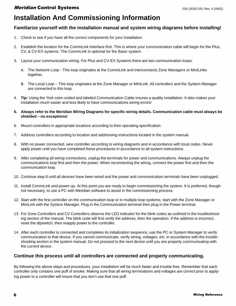
Familiarize yourself with the installation manual and system wiring diagrams before installing!
1. Check to see if you have all the correct components for your installation.
2. Establish the location for the CommLink Interface first. This is where your communication cable will begin for the Plus,CV, & CV-EX systems. The CommLink is optional for the Basic system.
3. Layout your communication wiring. For Plus and CV-EX Systems there are two communication loops:
A. The Network Loop - This loop originates at the CommLink and interconnects Zone Managers or MiniLinkstogether.
B. The Local Loop – This loop originates at the Zone Manager or MiniLink. All controllers and the System Managerare connected to this loop.
4. Tip: Using the York color-coded and labeled Communication Cable insures a quality installation. It also makes yourinstallation much easier and less likely to have communications wiring errors!
5. Always refer to the Meridian Wiring Diagrams for specific wiring details. Communication cable must always beshielded – no exceptions!
6. Mount controllers in appropriate locations according to their operating specification.
7. Address controllers according to location and addressing instructions located in the system manual.
8. With no power connected, wire controller according to wiring diagrams and in accordance with local codes. Neverapply power until you have completed these procedures in accordance to all system instructions.
9. After completing all wiring connections, unplug the terminals for power and communications. Always unplug thecommunications loop first and then the power. When reconnecting the wiring, connect the power first and then thecommunication loop.
10. Continue step 8 until all devices have been wired and the power and communication terminals have been unplugged.
11. Install CommLink and power-up. At this point you are ready to begin commissioning the system. It is preferred, thoughnot necessary, to use a PC with Meridian software to assist in the commissioning process.
12. Start with the first controller on the communication loop or in multiple loop systems; start with the Zone Manager orMiniLink with the System Manager. Plug in the Communication terminal then plug in the Power terminal.
13. For Zone Controllers and CV Controllers observe the LED indicator for the blink codes as outlined in the troubleshoot-ing section of the manual. The blink code will first verify the address, then the operation. If the address is incorrect,reset the dipswitch, then reapply power to the controller.
14. After each controller is connected and completes its initialization sequence, use the PC or System Manager to verifycommunication to that device. If you cannot communicate, verify wiring, voltages, etc. in accordance with the trouble-shooting section in the system manual. Do not proceed to the next device until you are properly communicating withthe current device.
Continue this process until all controllers are connected and properly communicating.
By following the above steps and procedures, your installation will be much faster and trouble free. Remember that eachcontroller only contains one puff of smoke. Making sure that all wiring terminations and voltages are correct prior to apply-ing power to a controller will insure that you don’t use that one puff.
Installation And Commissioning Information

7Wiring Reference
Meridian Control Systems035-18352-001 Rev. A (0602)
CV SystemCV SystemCV SystemCV SystemCV System
WWWWWiring Diairing Diairing Diairing Diairing Diagggggrrrrramsamsamsamsams

Wiring Reference8
Meridian Control Systems 035-18352-001 Rev. A (0602)
Computer(Optional)
CommLink IISingle LoopInterface
#30#1
RS-4859600 Baud
SupplyAir
Sensor
RS-485Local Loop RS-485
Local LoopEconomizer
(Actuator By Others)
Generic AlarmDirty Filter Alarm Shown
Room Sensorwith OptionalOverride & Adj.
F
Typical CV Controller Wiring
* Only One Outside Air SensorIs Required Per CV System
110/24 VAC
110/9 VAC
Local Loop
Power Pak(14 VA@24VAC)
Power Pak
Typical Local Loop Wiring2 Conductor Twisted Pair With Shield(Belden #82760 Or Equivalent)
*Outside AirSensor
Loop #1
24VAC(20 VA)
24VAC(20 VA)
24VAC
24VAC(20 VA)
CVControllers
System Manager
Notes:
1.)24 VAC Must Be ConnectedSo That All Ground WiresRemain Common.
RELAY
OUTPUT
COM
1-3
OUT
OUT1
2
COM4-5
OUT
OUT
OUT
3
4
5
24VAC
GNDPWR
COMM
T
SHLD
LD4
REC.
12V
AIN1
2
3
4
5
GND
GND
AOUT
AIN
AIN
AIN
AIN
4-5
OUT
COMM
TEST
32K
8K
RAM EPROM
ADDRESS ADD
PRESSURE
SENSOR
485
COMM
R
YS101564
EWDOG
0-5
VDC
0-1
VDC
CPU
RELAY
OUTPUT
COM
1-3
OUT
OUT1
2
COM4-5
OUT
OUT
OUT
3
4
5
24VAC
GNDPWR
COMM
T
SHLD
LD4
REC.
12V
AIN1
2
3
4
5
GND
GND
AOUT
AIN
AIN
AIN
AIN
4-5
OUT
COMM
TEST
32K
8K
RAM EPROM
ADDRESS ADD
PRESSURE
SENSOR
485
COMM
R
YS101564
EWDOG
0-5
VDC
0-1
VDC
CPU
RELAY
OUTPUT
COM
1-3
OUT
OUT1
2
COM4-5
OUT
OUT
OUT
3
4
5
24VAC
GNDPWR
COMM
T
SHLD
LD4
REC.
12V
AIN1
2
3
4
5
GND
GND
AOUT
AIN
AIN
AIN
AIN
4-5
OUT
COMM
TEST
32K
8K
RAM EPROM
ADDRESS ADD
PRESSURE
SENSOR
485
COMM
R
YS101564
EWDOG
0-5
VDC
0-1
VDC
CPU
COMMLINKII
COMMLINKII
L
C
M
M
O
O
O
O
M
D
P
PE
3.)The Local Loop May Have Up To 30CV Controllers Connected To It.
5.)For Individual Component Wiring SeeSpecific Component Wiring Diagram.
6.)It Is Recommended That All CVControllers Address Switches AreSet Before Installation To TheirRespective Constant Volume Units. FILENAME
JOB NAME
DATE: 02/22/01 B. CREWS
DESCRIPTION:PAGE
DRAWN BY:
MCVSYW1.CDR
Meridian CV
System Wiring Diagram
See Drawing Filename: MCVSYW3.CDR for CV Controller Wiring Details
SeeFor
Commlink WiringDetails
Drawing Filename:MCVSYW4.CDR
SeeFor System Manager Wiring Details
Drawing Filename: MCVSYW2.CDR
1
2.)All Wiring To Be In AccordanceWith Local And National ElectricalCodes and Specifications.
4.)All Communication Wiring To Be 18Ga. Minimum, 2 Conductor TwistedPair With Shield. Belden #82760 OrEquivalent.
Remote Link(Optional)
Remote
Link
C
O
N
T
R
O
L
S
C
O
N
T
R
O
L
S
SIG
DET
RDY
SND
REC
PWR
24VAC(25 VA)
Clear WindowArea
65
4
DEC
7MINU
S
0
CLEA
R98
1
32
MEN
U
Override
Communication
ENTER
ESC
Alarm
System
Manager
-
Heatingand Air C
onditioning
®

9Wiring Reference
Meridian Control Systems035-18352-001 Rev. A (0602)
Notes:
FILENAME
DATE: B. CREWS
DESCRIPTION:PAGE
DRAWN BY:
System Manager Wiring2
JOB NAME1.)24 VAC Must Be Connected So
That All Ground Wires RemainCommon.
2.)All Wiring To Be In AccordanceWith Local And National ElectricalCodes And Specifications.
3.) All Communication Wiring To Be2 Conductor Twisted Pair WithShield. Use Belden #82760 OrEquivalent.
06/11/01
MCVSYW2.CDR
Meridian CV
The Ideal Recommended Location For The System Manager Is As TheFirst Device On The Local Loop. The System Manager May Be Connected To TheLocal Loop At Any Point On The Local Loop.
System Manager
654
DEC
7
MINUS0 CLEAR
98
1 32 MENU
Override
Communication
ENTER
ESC
Alarm
To MiniLink, Or Next DeviceOn Local Loop
Line Voltage
See Note 1
See Note 324VAC
GND
Required VA For TransformerSystem Manager = 25VA Max.
MADE IN
THE USA
EP
RO
M
1000uF10v
YS101806 REV. 1
DSPY1
UNIVERSAL SMART DISP. UNIT
SYSTEM MANAGER
SERIAL # :
U13SERIAL #
1000uF10v
C9
470uF50v
D2
PC
B80C
552-5
-16W
P
442860=2/5
DfD
9722V
7Y
PH
ILIP
S
CX
13
LD8
CX
9
SS0017
vx.xx 1234
V62C518256L-70P
U9
U8
LD7
RN
1
LD6
U7
CX7
74H
C573
LD5
LD4
74HC573
CX
8
RN2
X2
CX
4
470uF50v
TB
2
GND
24VAC
R10
75176
RS-485
COMM
U12
CX
12
RA
M
SC1
T
TB
1
SHLD
C7
C11
L1
C4
R
D6
8583
U6
CX6C3
D3
24C
128
U5
R7
VAR1
D4
PJ1
R3
U1
74HC259
LD3
LD2
LD1
R2
R1
EW
DO
G
PH
ILIP
S
U3
U2
CX
1
82B715CX5
CX
3
U3
DSPY1
R5
D1
R6
MC
34064A
C6
R11
9936 C8
R9
U10
U11
R8
R12
C5
74H
C923
CX10
P1
R4
RV1
C2
C1
X1

Wiring Reference10
Meridian Control Systems 035-18352-001 Rev. A (0602)
Notes:
FILENAME
DATE: B. CREWS
DESCRIPTION:PAGE
DRAWN BY:
Line Voltage
Line Voltage
See Note 1
See Note 1
Wx or Yx (Htg or Clg Stage x)
Wx or Yx (Htg or Clg Stage x)
Wx or Yx (Htg or Clg Stage x)
Wx or Yx (Htg or Clg Stage x)
G (Fan-On/Off)
R (24VAC)
Constant VolumeUnit Connections
CV Controller
R
SH
T
R
SH
T
R
SH
T
R
SH
T
All Comm Loop Wiring IsStraight Thru
Required VA For TransformerEach CV Controller = 20VA Max.
24VAC
24VAC
GND
GND
Mount In HVACUnit SupplyAir Duct
Auxiliary AlarmInput
Switch SuppliedBy Others
DischargeAir Temp.Sensor
AOUT
GND
GND
AIN5
AIN1AIN2AIN3AIN4
12V
GND
AUX
TMP
NORMAL
OVR
RELO
C
REMR
O
AW
COMM
REC.
LD4
T
R
SHLD
GND
24VAC
PWR
COMM
TEST
16
8421
RELAYOUTPUTS
COM4-5
OUT1
OUT2
OUT3
OUT4
OUT5
COM1-3
Caution!CV Controllers Must Have Address Switches SetBetween 1 And 30 ( Up To 30 Units Per Local Loop ).
Room Sensor
Diagnostic Blink Code LED
RAM
EPROM
Local LoopRS-485
9600 Baud(See Note 3).
Connect ToNext Controller
And/OrMiniLink OnLocal Loop
Address Switch Shown IsSet For Address 1
Address Switch Shown IsSet For Address 13
ControllerAddress Switch
This Switch Must BeIn The ON PositionAs Shown
These Switches Should BeIn The OFF PositionAs Shown
Note:The Power To The CV Controller Must Be RemovedAnd Reconnected After Changing The AddressSwitch Settings In Order For Any Changes To TakeEffect.
Caution:Disconnect All Communication Loop WiringFrom The CV Controller Before Removing PowerFrom The CV Controller. Reconnect Power AndThen Reconnect Communication Loop Wiring.
ADDRESS ADD
ADDRESS ADD
ADDRESSADD
ADDRESSADD
The Address For Each ControllerMust Be Unique To The Other Controllers
On The Local Loop
Connection ToAUX Terminal is ReqdOnly When SensorIs Specified WithSlide Adjust Option
JOB NAME1.)24 VAC Must Be Connected SoThat All Ground Wires RemainCommon.
2.)All Wiring To Be In AccordanceWith Local And National ElectricalCodes And Specifications.
3.)All Communication Wiring To Be2 Conductor Twisted Pair WithShield. Use Belden #82760 OrEquivalent.
01/10/01
3
EconomizerActuator
(Belimo Shown)Consult Factory ForOther ManufacturersWiring Connections
Note:Up To 4 Stages Of Heating Or Cooling Or AnyCombination Of Each Is Allowed And ProgrammableVia The System Manager or ZoneView Software. If TheUnit Has Heat, Heating Stages Must Be Connected ToThe First Outputs in Consecutive Order And CoolingStages To The Remaining Outputs In Consecutive Order.
Outside AirTemp. Sensor(See Note 4)
4.)Only One Outside Air Sensor IsRequired Per System. It May BeConnected To Any CV Controller Or OnThe System. If A Wetbulb ModuleController Is Used The OA Sensor MustBe Connected To The Wetbulb Module.
CV Controller Wiring
MCVSYW3.CDR
Meridian CV
Y 3
+ 2
COM 1
11Wiring Reference
Meridian Control Systems035-18352-001 Rev. A (0602)
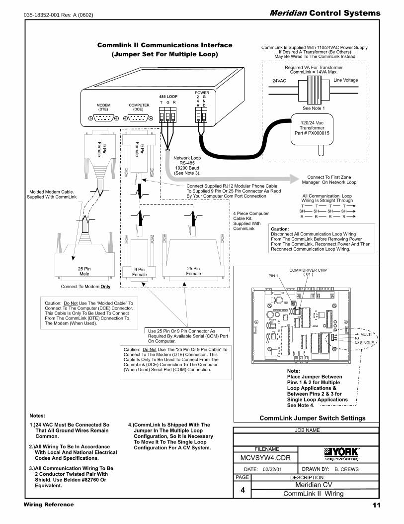
Commlink II Communications Interface
(Jumper Set For Multiple Loop)
Caution: Use The “Molded Cable” ToConnect To The Computer (DCE) Connector.This Cable Is Only To Be Used To ConnectFrom The CommLink (DTE) Connection ToThe Modem (When Used).
Do Not
Caution:Disconnect All Communication Loop WiringFrom The CommLink Before Removing PowerFrom The CommLink. Reconnect Power And ThenReconnect Communication Loop Wiring.
Use 25 Pin Or 9 Pin Connector AsRequired By Available Serial (COM) PortOn Computer.
JOB NAME
Caution: Use The “25 Pin Or 9 Pin Cable” ToConnect To The Modem (DTE) Connector.. ThisCable Is Only To Be Used To Connect From TheCommLink (DCE) Connection To The Computer
Serial Port (COM) Connection.
Do Not
(When Used) Note:Place Jumper BetweenPins 1 & 2 for MultipleLoop Applications &Between Pins 2 & 3 forSingle Loop ApplicationsSee Note 4.
COMM DRIVER CHIP( U1 )PIN 1
MULTI
SINGLE
123
CommLink Jumper Switch SettingsNotes:
FILENAME
DATE: B. CREWS
DESCRIPTION:PAGE
DRAWN BY:
CommLink II Wiring4
R
SH
T
R
SH
T
R
SH
T
R
SH
T
All Communication LoopWiring Is Straight Through
Connect To First ZoneManager On Network Loop
Network LoopRS-485
19200 Baud(See Note 3).
Line Voltage
See Note 1
24VAC
Required VA For TransformerCommLink = 14VA Max.
CommLink Is Supplied With 110/24VAC Power Supply.If Desired A Transformer (By Others)
May Be Wired To The CommLink Instead
Molded Modem Cable.Supplied With CommLink
(DTE)MODEM COMPUTER
(DCE)
GT R
POWER
4 Piece ComputerCable Kit.Supplied WithCommLink
Connect To Modem .Only
9Pin
Female
9 PinFemale
25 PinFemale
9Pin
Female
120/24 VacTransformer
Part # PX000015
25 PinMale
Connect Supplied RJ12 Modular Phone CableTo Supplied 9 Pin Or 25 Pin Connector As ReqdBy Your Computer Com Port Connection
1.)24 VAC Must Be Connected SoThat All Ground Wires RemainCommon.
2.)All Wiring To Be In AccordanceWith Local And National ElectricalCodes And Specifications.
3.)All Communication Wiring To Be2 Conductor Twisted Pair WithShield. Use Belden #82760 OrEquivalent.
02/22/01
MCVSYW4.CDR
Meridian CV
4.)CommLink Is Shipped With TheJumper In The Multiple LoopConfiguration, So It Is NecessaryTo Move It To The Single LoopConfiguration For A CV System.
485 LOOP 24V
GND

Wiring Reference12
Meridian Control Systems 035-18352-001 Rev. A (0602)
Notes:

13Wiring Reference
Meridian Control Systems035-18352-001 Rev. A (0602)
CV-EX SystemCV-EX SystemCV-EX SystemCV-EX SystemCV-EX System
WWWWWiring Diairing Diairing Diairing Diairing Diagggggrrrrramsamsamsamsams

Wiring Reference14
Meridian Control Systems 035-18352-001 Rev. A (0602)
Computer(Optional)
CommLink IIMultiple LoopInterface
System Manager
#30
#30
#30
#30
#1
#1
#1
#1
RS-48519200 Baud
RS-48519200 Baud
RS-4859600 Baud
RS-4859600 Baud
RS-4859600 Baud
RS-4859600 Baud
SupplyAir
Sensor
RS-485Local Loop RS-485
Local LoopEconomizer
(Actuator By Others)
Generic AlarmDirty Filter Alarm Shown
Room Sensorwith OptionalOverride & Adj.
F
Typical CV Controller Wiring
* Only One Outside Air SensorIs Required Per CV-EX System
110/24 VAC
Loop # 1MiniLink
Loop # 2MiniLink
Loop # 3MiniLink
Loop # 4MiniLink
Network Loop
Network Loop
Power Pak(14 VA@24VAC)
Local Loop
Local Loop
Typical Network & Local Loop Wiring2 Conductor Twisted Pair With Shield(Belden #82760 Or Equivalent)
Local Loop
Local Loop
*Outside AirSensor
Loop #1
Loop #2
Loop #3
Loop #4
24VAC(25 VA)
24VAC(20 VA)
24VAC(20 VA)
24VAC(20 VA)
24VAC(20 VA)
24VAC(14 VA)
24VAC(14 VA)
24VAC(14 VA)
24VAC(14 VA)
24VAC(20 VA)
24VAC(20 VA)
24VAC
24VAC(20 VA)
24VAC(20 VA)
24VAC(20 VA)
CVControllers
CVControllers
CVControllers
CVControllers
SeeFor
Commlink WiringDetails
Drawing Filename:MCVEXSYW5.CDR
MCVEXSYW4.CDR ForMiniLink Wiring Details
SeeFor System
Manager Wiring Details
Drawing Filename:MCVEXSYW2.CDR
See For CV Controller WiringDrawing Filename: MCVEXSYW3.CDR
110/9 VACPower Pak
Remote Link(Optional)
Remote
Link
C
O
N
T
R
O
L
S
SIG
DET
RDY
SND
REC
PWR
Notes:
1.)24 VAC Must Be Connected SoThat All Ground Wires RemainCommon.
RELAY
OUTPUT
COM
1-3
OUT
OUT1
2
COM4-5
OUT
OUT
OUT
3
4
5
24VAC
GNDPWR
COMM
T
SHLD
LD4
REC.
12V
AIN1
2
3
4
5
GND
GND
AOUT
AIN
AIN
AIN
AIN
4-5
OUT
COMM
TEST
32K
8K
RAM EPROM
ADDRESS ADD
PRESSURE
SENSOR
485
COMM
R
YS101564
EWDOG
0-5
VDC
0-1
VDC
CPU
RELAY
OUTPUT
COM
1-3
OUT
OUT1
2
COM4-5
OUT
OUT
OUT
3
4
5
24VAC
GNDPWR
COMM
T
SHLD
LD4
REC.
12V
AIN1
2
3
4
5
GND
GND
AOUT
AIN
AIN
AIN
AIN
4-5
OUT
COMM
TEST
32K
8K
RAM EPROM
ADDRESS ADD
PRESSURE
SENSOR
485
COMM
R
YS101564
EWDOG
0-5
VDC
0-1
VDC
CPU
RELAY
OUTPUT
COM
1-3
OUT
OUT1
2
COM4-5
OUT
OUT
OUT
3
4
5
24VAC
GNDPWR
COMM
T
SHLD
LD4
REC.
12V
AIN1
2
3
4
5
GND
GND
AOUT
AIN
AIN
AIN
AIN
4-5
OUT
COMM
TEST
32K
8K
RAM EPROM
ADDRESS ADD
PRESSURE
SENSOR
485
COMM
R
YS101564
EWDOG
0-5
VDC
0-1
VDC
CPU
RELAY
OUTPUT
COM
1-3
OUT
OUT1
2
COM4-5
OUT
OUT
OUT
3
4
5
24VAC
GNDPWR
COMM
T
SHLD
LD4
REC.
12V
AIN1
2
3
4
5
GND
GND
AOUT
AIN
AIN
AIN
AIN
4-5
OUT
COMM
TEST
32K
8K
RAM EPROM
ADDRESS ADD
PRESSURE
SENSOR
485
COMM
R
YS101564
EWDOG
0-5
VDC
0-1
VDC
CPU
RELAY
OUTPUT
COM
1-3
OUT
OUT1
2
COM4-5
OUT
OUT
OUT
3
4
5
24VAC
GNDPWR
COMM
T
SHLD
LD4
REC.
12V
AIN1
2
3
4
5
GND
GND
AOUT
AIN
AIN
AIN
AIN
4-5
OUT
COMM
TEST
32K
8K
RAM EPROM
ADDRESS ADD
PRESSURE
SENSOR
485
COMM
R
YS101564
EWDOG
0-5
VDC
0-1
VDC
CPU
RELAY
OUTPUT
COM
1-3
OUT
OUT1
2
COM4-5
OUT
OUT
OUT
3
4
5
24VAC
GNDPWR
COMM
T
SHLD
LD4
REC.
12V
AIN1
2
3
4
5
GND
GND
AOUT
AIN
AIN
AIN
AIN
4-5
OUT
COMM
TEST
32K
8K
RAM EPROM
ADDRESS ADD
PRESSURE
SENSOR
485
COMM
R
YS101564
EWDOG
0-5
VDC
0-1
VDC
CPU
RELAY
OUTPUT
COM
1-3
OUT
OUT1
2
COM4-5
OUT
OUT
OUT
3
4
5
24VAC
GNDPWR
COMM
T
SHLD
LD4
REC.
12V
AIN1
2
3
4
5
GND
GND
AOUT
AIN
AIN
AIN
AIN
4-5
OUT
COMM
TEST
32K
8K
RAM EPROM
ADDRESS ADD
PRESSURE
SENSOR
485
COMM
R
YS101564
EWDOG
0-5
VDC
0-1
VDC
CPU
RELAY
OUTPUT
COM
1-3
OUT
OUT1
2
COM4-5
OUT
OUT
OUT
3
4
5
24VAC
GNDPWR
COMM
T
SHLD
LD4
REC.
12V
AIN1
2
3
4
5
GND
GND
AOUT
AIN
AIN
AIN
AIN
4-5
OUT
COMM
TEST
32K
8K
RAM EPROM
ADDRESS ADD
PRESSURE
SENSOR
485
COMM
R
YS101564
EWDOG
0-5
VDC
0-1
VDC
CPU
RELAY
OUTPUT
COM
1-3
OUT
OUT1
2
COM4-5
OUT
OUT
OUT
3
4
5
24VAC
GNDPWR
COMM
T
SHLD
LD4
REC.
12V
AIN1
2
3
4
5
GND
GND
AOUT
AIN
AIN
AIN
AIN
4-5
OUT
COMM
TEST
32K
8K
RAM EPROM
ADDRESS ADD
PRESSURE
SENSOR
485
COMM
R
YS101564
EWDOG
0-5
VDC
0-1
VDC
CPU
COMMLINKII
COMMLINKII
L
C
M
M
O
O
O
O
M
D
P
PE
LOOP
LOOP
3232
1616
8
4
1
2
MINILINKMINILINK
NETWORK
NETWORK
T
SHSH
R
24V24VAACC
GNDGND
T
SHSH
R
LOOP
LOOP
3232
1616
8
4
1
2
MINILINKMINILINK
NETWORK
NETWORK
T
SHSH
R
24V24VAACC
GNDGND
T
SHSH
R
LOOP
LOOP
3232
1616
8
4
1
2
MINILINKMINILINK
NETWORK
NETWORK
T
SHSH
R
24V24VAACC
GNDGND
T
SHSH
R
LOOP
LOOP
3232
1616
8
4
1
2
MINILINKMINILINK
NETWORK
NETWORK
T
SHSH
R
24VAC24VAC
GNDGND
T
SHSH
R
3.)Each Local Loop May Have Up To 30CV Controllers Connected To It. EachLocal Loop Requires A Minlink.
4.)All Communication Wiring To Be 18Ga. Minimum, 2 Conductor TwistedPair With Shield. Belden #82760 OrEquivalent.
5.)Systems May Consist Of Up To 4Local Loops (120 CV Controllers).Consult Factory For Systems ThatExceed These Quantities.
6.)For Individual Component Wiring SeeSpecific Component Wiring Diagram.
7.)It Is Recommended That All CVControllers Address Switches AreSet Before Installation To TheirRespective Constant Volume Units.
2.)All Wiring To Be In Accordance WithLocal And National Electrical Codesand Specifications. FILENAME
JOB NAME
DATE: 02/22/01 B. CREWS
DESCRIPTION:PAGE
DRAWN BY:
MCVEXSYW1.CDR
Meridian CV-EX
System Wiring Diagram1
C
O
N
T
R
O
L
S
Clear WindowArea
65
4
DEC
7MINU
S
0
CLEA
R98
1
32
MEN
U
Override
Communication
ENTER
ESC
Alarm
System
Manager
-
Heatingand Air C
onditioning
®

15Wiring Reference
Meridian Control Systems035-18352-001 Rev. A (0602)
FILENAME
DATE: B. CREWS
DESCRIPTION:PAGE
DRAWN BY:
System Manager Wiring2
JOB NAME
06/11/01
MCVEXSYW2.CDR
Meridian CV-EX
Notes:
1.)24 VAC Must Be Connected SoThat All Ground Wires RemainCommon.
2.)All Wiring To Be In AccordanceWith Local And National ElectricalCodes And Specifications.
3.) All Communication Wiring To Be2 Conductor Twisted Pair WithShield. Use Belden #82760 OrEquivalent.
The Ideal Recommended Location For The System Manager Is As TheFirst Device On The Local Loop, (Connect To MiniLink Local Loop Terminals)Although The System Manager May Be Connected To Any Local Loop AtAny Point On The Local Loop.The System Manager Will Not Operate Correctly If Attached To The Network Loop.
DO NOT CONNECT TO THE NETWORK LOOP.
System Manager
654
DEC
7
MINUS0 CLEAR
98
1 32 MENU
Override
Communication
ENTER
ESC
Alarm
To MiniLink, Or Next DeviceOn Local Loop
Line Voltage
See Note 1
See Note 324VAC
GND
Required VA For TransformerSystem Manager = 25VA Max.
MADE IN
THE USA
EP
RO
M
1000uF10v
YS101806 REV. 1
DSPY1
UNIVERSAL SMART DISP. UNIT
SYSTEM MANAGER
SERIAL # :
U13SERIAL #
1000uF10v
C9
470uF50v
D2
PC
B80C
552-5
-16W
P
442860=2/5
DfD
9722V
7Y
PH
ILIP
S
CX
13
LD8
CX
9
SS0017
vx.xx 1234
V62C518256L-70P
U9
U8
LD7
RN
1
LD6
U7
CX7
74H
C573
LD5
LD4
74HC573
CX
8
RN2
X2
CX
4
470uF50v
TB
2
GND
24VAC
R10
75176
RS-485
COMM
U12
CX
12
RA
M
SC1
T
TB
1
SHLD
C7
C11
L1
C4
R
D6
8583
U6
CX6C3
D3
24C
128
U5
R7
VAR1
D4
PJ1
R3
U1
74HC259
LD3
LD2
LD1
R2
R1
EW
DO
G
PH
ILIP
S
U3
U2
CX
1
82B715CX5
CX
3
U3
DSPY1
R5
D1
R6
MC
34064A
C6
R11
9936 C8
R9
U10
U11
R8
R12
C5
74H
C923
CX10
P1
R4
RV1
C2
C1
X1

Wiring Reference16
Meridian Control Systems 035-18352-001 Rev. A (0602)
Notes:
FILENAME
DATE: B. CREWS
DESCRIPTION:PAGE
DRAWN BY:
Line Voltage
Line Voltage
See Note 1
See Note 1
Wx or Yx (Htg or Clg Stage x)
Wx or Yx (Htg or Clg Stage x)
Wx or Yx (Htg or Clg Stage x)
Wx or Yx (Htg or Clg Stage x)
G (Fan-On/Off)
R (24VAC)
Constant VolumeUnit Connections
CV Controller
R
SH
T
R
SH
T
R
SH
T
R
SH
T
All Comm Loop Wiring IsStraight Thru
Required VA For TransformerEach CV Controller = 20VA Max.
24VAC
24VAC
GND
GND
Mount In HVACUnit SupplyAir Duct
Auxiliary AlarmInput
Switch SuppliedBy Others
DischargeAir Temp.Sensor
AOUT
GND
GND
AIN5
AIN1AIN2AIN3AIN4
12V
GND
AUX
TMP
NORMAL
OVR
RELO
C
REMR
O
AW
COMM
REC.
LD4
T
R
SHLD
GND
24VAC
PWR
COMM
TEST
16
8421
RELAYOUTPUTS
COM4-5
OUT1
OUT2
OUT3
OUT4
OUT5
COM1-3
Caution!CV Controllers Must Have Address Switches SetBetween 1 And 30 ( Up To 30 Units Per Local Loop ).
Room Sensor
Diagnostic Blink Code LED
RAM
EPROM
Local LoopRS-485
9600 Baud(See Note 3).
Connect ToNext Controller
And/OrMiniLink OnLocal Loop
Address Switch Shown IsSet For Address 1
Address Switch Shown IsSet For Address 13
ControllerAddress Switch
This Switch Must BeIn The ON PositionAs Shown
These Switches Should BeIn The OFF PositionAs Shown
Note:The Power To The CV Controller Must Be RemovedAnd Reconnected After Changing The AddressSwitch Settings In Order For Any Changes To TakeEffect.
Caution:Disconnect All Communication Loop WiringFrom The CV Controller Before Removing PowerFrom The CV Controller. Reconnect Power AndThen Reconnect Communication Loop Wiring.
ADDRESS ADD
ADDRESS ADD
ADDRESSADD
ADDRESSADD
The Address For Each ControllerMust Be Unique To The Other Controllers
On The Local Loop
Connection ToAUX Terminal is ReqdOnly When SensorIs Specified WithSlide Adjust Option
JOB NAME1.)24 VAC Must Be Connected SoThat All Ground Wires RemainCommon.
2.)All Wiring To Be In AccordanceWith Local And National ElectricalCodes And Specifications.
3.)All Communication Wiring To Be2 Conductor Twisted Pair WithShield. Use Belden #82760 OrEquivalent.
01/10/00
3
EconomizerActuator
(Belimo Shown)Consult Factory ForOther ManufacturersWiring Connections
Note:Up To 4 Stages Of Heating Or Cooling Or AnyCombination Of Each Is Allowed And ProgrammableVia The System Manager or ZoneView Software. If TheUnit Has Heat, Heating Stages Must Be Connected ToThe First Outputs in Consecutive Order And CoolingStages To The Remaining Outputs In Consecutive Order.
Outside AirTemp. Sensor(See Note 4)
4.)Only One Outside Air Sensor IsRequired Per System. It May BeConnected To Any CV Controller Or OnThe System. If A Wetbulb ModuleController Is Used The OA Sensor MustBe Connected To The Wetbulb Module.
CV Controller Wiring
MCVEXSYW3.CDR
Meridian CV-EX
Y 3
+ 2
COM 1

17Wiring Reference
Meridian Control Systems035-18352-001 Rev. A (0602)
Notes:
FILENAME
DATE: B. CREWS
DESCRIPTION:PAGE
DRAWN BY:
MiniLink Wiring4
R
SH
T
R
SH
T
R
SH
T
R
SH
T
All Communication LoopWiring Is Straight Through
1632
8421
Caution!The MiniLinks Must Have Address Switches Set Between 1And 4 (Up To 4 MiniLinks Are Allowed Per CV-EX System).The MiniLinks Should Be Addressed In Consecutive OrderStarting With Address #1. Address #1 Must Be Present OnThe Loop For The System To Function.
Address Switch Shown IsSet For Address 1
Address Switch Shown IsSet For Address 4
MiniLinkAddress Switch
These Switches Must BeIn The OFF PositionAs Shown
Required VA For TransformerMiniLink = 10VA Max.
See Note 1.
Note:The Power To The MiniLink Must Be Removed AndReconnected After Changing The Address Switch
Caution:Disconnect All Communication Loop WiringFrom The MiniLink Before Removing PowerFrom The MiniLink. Reconnect Power And ThenReconnect Communication Loop Wiring.
ADD
ADD ADD
The Address For Each MiniLinkMust Be Unique To The Other MiniLinksOn The Network Loop. Loop #1 MiniLink
Should Be Addressed As #1Loop #2 MiniLink Should Be Addressed
As #2 Etc..
LOOP
MINILINK
24VAC
GND
T
SH
R
32
16
8
4
1
2
OFF >
RockerDown
Local LoopRS-485
9600 Baud(See Note 3).
Connect To NextController or
System ManagerOn Local Loop
Connect To NextMiniLink And/OrCommLink OnNetwork Loop
Network LoopRS-485
19200 Baud(See Note 3).
Line Voltage24VAC
Minilink Communications Interface
JOB NAME1.)24 VAC Must Be Connected So
That All Ground Wires RemainCommon.
2.)All Wiring To Be In AccordanceWith Local And National ElectricalCodes And Specifications.
3.) All Communication Wiring To Be2 Conductor Twisted Pair WithShield. Use Belden #82760 OrEquivalent.
07/20/98
MCVEXSYW4.CDR
Meridan CV-EX
ADD
NETWORK
SH
T
R

Wiring Reference18
Meridian Control Systems 035-18352-001 Rev. A (0602)
Commlink II Communications Interface
(Jumper Set For Multiple Loop)
Caution: Use The “Molded Cable” ToConnect To The Computer (DCE) Connector.This Cable Is Only To Be Used To ConnectFrom The CommLink (DTE) Connection ToThe Modem (When Used).
Do Not
Caution:Disconnect All Communication Loop WiringFrom The CommLink Before Removing PowerFrom The CommLink. Reconnect Power And ThenReconnect Communication Loop Wiring.
Use 25 Pin Or 9 Pin Connector AsRequired By Available Serial (COM) PortOn Computer.
JOB NAME
Caution: Use The “25 Pin Or 9 Pin Cable” ToConnect To The Modem (DTE) Connector.. ThisCable Is Only To Be Used To Connect From TheCommLink (DCE) Connection To The Computer
Serial Port (COM) Connection.
Do Not
(When Used) Note:Place Jumper BetweenPins 1 & 2 for MultipleLoop Applications &Between Pins 2 & 3 forSingle Loop ApplicationsSee Note 4.
COMM DRIVER CHIP( U1 )PIN 1
MULTI
SINGLE
123
CommLink Jumper Switch SettingsNotes:
FILENAME
DATE: B. CREWS
DESCRIPTION:PAGE
DRAWN BY:
CommLink II Wiring5
R
SH
T
R
SH
T
R
SH
T
R
SH
T
All Communication LoopWiring Is Straight Through
Connect To First ZoneManager On Network Loop
Network LoopRS-485
19200 Baud(See Note 3).
Line Voltage
See Note 1
24VAC
Required VA For TransformerCommLink = 14VA Max.
CommLink Is Supplied With 110/24VAC Power Supply.If Desired A Transformer (By Others)
May Be Wired To The CommLink Instead
Molded Modem Cable.Supplied With CommLink
(DTE)MODEM
485 LOOP485 LOOP
COMPUTER(DCE)
GT R
G2
V4
DN
POWER
4 Piece ComputerCable Kit.Supplied WithCommLink
Connect To Modem .Only
9Pin
Female
9 PinFemale
25 PinFemale
9Pin
Female
120/24 VacTransformer
25 PinMale
Connect Supplied RJ12 Modular Phone CableTo Supplied 9 Pin Or 25 Pin Connector As ReqdBy Your Computer Com Port Connection
1.)24 VAC Must Be Connected SoThat All Ground Wires RemainCommon.
2.)All Wiring To Be In AccordanceWith Local And National ElectricalCodes And Specifications.
3.)All Communication Wiring To Be2 Conductor Twisted Pair WithShield. Use Belden #82760 OrEquivalent.
12/29/00
MCVEXSYW5.CDR
Meridian CV-EX
4.)CommLink Is Shipped With TheJumper In The Multiple LoopConfiguration, So It Is Not NecessaryTo Move It For A CV-EX System.

19Wiring Reference
Meridian Control Systems035-18352-001 Rev. A (0602)
Basic SystemBasic SystemBasic SystemBasic SystemBasic System
WWWWWiring Diairing Diairing Diairing Diairing Diagggggrrrrramsamsamsamsams

Wiring Reference20
Meridian Control Systems 035-18352-001 Rev. A (0602)
ZoneManager
SupplyAir TempSensor
To HVAC UnitControl Panel
ReturnAir TempSensor
Bypass AirDamper
Economizer(Actuator By Others)
Outside AirTemp Sensor
StaticPressureSensor
Local Loop
Zone Air DampersUp to 16 Zone Air Dampers Allowed
#1 #16
24VAC(25 VA)
24VAC(10 VA)
24VAC(10 VA)
Remote Link(Optional)
Computer(Optional)
CommLink IISingle LoopInterface(Optional)
RS-4859600 Baud
110/24 VAC
110/9 VAC
Power Pak(14 VA@24VAC)
Power Pak
W
C
LI
ATTMASTER
ONTRO
S,NC
W
C
LI
ATTMASTER
ONTRO
S,NC
COMMLINKII
COMMLINKII
L
C
M
M
O
O
O
O
M
D
P
PE
Notes:
1.)24 VAC Must Be Connected SoThat All Ground Wires RemainCommon.
3.)The Local Loop May Have Up To 16Zone Controllers Connected.
4.)All Communication Wiring To Be 18Ga. Minimum, 2 Conductor TwistedPair With Shield. Belden #82760 OrEquivalent.
5.)For Individual Component Wiring SeeSpecific Component Wiring Diagram.
6.)It Is Recommended That AllControllers Address Switches AreSet Before Installation.
2.)All Wiring To Be In Accordance WithLocal And National Electrical Codesand Specifications.
SeeFor
Zone Manager WiringDetails
Drawing Filename:MBAWRNEW3.CDR
See
For CommLink WiringDetails
Drawing Filename:MBAWRNEW6.CDR
See
For Zone ControllerWiring Details
Drawing Filename:MBAWRNEW4.CDR
Remote
Link
C
O
N
T
R
O
L
S
SIG
DET
RDY
SND
REC
PWR
FAN
COOL1
COOL2
HEAT
1
HEAT
2
BYPA
SSOPE
N
BYPA
SSCL
OSE
COMMUN
ICATION
ALAR
M
A=AL
LZO
NES
B=EA
CHZO
NE
C=HV
ACUN
IT/CLEAR
D=AL
ARMS
#=STEP
/ENT
ER
* =DE
CIMAL
+
+
+
+
Meridian
Cool
Mode
08-08-01
03:48PMFRI
OCCUPIED
NOALARMS
2
8
5
0
A
C
B
D
1
7
4
*
3
9
6
#
Heatingand Air C
onditioning
®
FILENAME
DATE: B. CREWS
DESCRIPTION:PAGE
DRAWN BY:
System Wiring Diagram1
JOB NAME
02/01/01
MBAWRNEW1.CDR
Meridian Basic

21Wiring Reference
Meridian Control Systems035-18352-001 Rev. A (0602)
If The Actuator WiringInterface You Have On YourSystem Looks Different FromThe One Shown Please SeePage 62 For Correct WiringInformation.
Zone Manager
Notes:
1.)24 VAC Must Be Connected SoThat All Ground Wires RemainCommon.
3.)All Communication Wiring To Be 18Ga. Minimum, 2 Conductor TwistedPair With Shield. Belden #82760 OrEquivalent.
4.)For Individual Component Wiring SeeSpecific Component Wiring Diagram.
5.)It Is Recommended That AllControllers Address Switches AreSet Before Installation
2.)All Wiring To Be In Accordance WithLocal And National Electrical Codesand Specifications.
RS-485Communications To Zone
Controllers
Return Air Temp.Sensor
Supply Air Temp.Sensor
LineVoltage
HVACUnit
24VAC Only
Red
Blk
To Relief / Exhaust Fans
Grn
StaticPick-up
StaticPressureSensor
Splice AsRequired
LO HI
GND
24VAC
Belimo Actuator Wiring Shown.Consult Factory For Other
Models Of Economizer Actuators.Some Actuators Require IsolationTransformers In Order To PreventDamage To The Controller Board.
WARNING!
Use Extreme Care When WiringEconomizer Actuators
Never Connect Or DisconnectWiring With Power Applied!
Never Apply Power If TheGnd ( 1 Com ) Terminal On TheActuator Is Not Connected.
See Note 1 &2
Outdoor Air Temp.Sensor
(See Note 4)
Aux3ForcedOccupiedMode
Aux1EconomizerDisable
Aux2FilterAlarm
Auxiliary Inputs( Dry Contacts )
R
G
Y1
Y2
W1
W2
Economizer Actuator
133 IN-LB
AF24-SR
1 COM
2 +
3 Y1
4 Y2
5 UBELIMO
For Detailed ConnectionsAnd Slave WiringSee Bypass ActuatorWiring Drawing Filename:MBAWRNEW3.CDR
Bypass Air DamperActuator
10
FILENAME
DATE: B. CREWS
DESCRIPTION:PAGE
DRAWN BY:
Zone Manager Wiring2
JOB NAME
02/01/01
MBAWRNEW2.CDR
Meridian Basic
C987
CABLE
R6
R5
HEAT 2 SW1
W2
W1
Y2
HEAT2
HEAT1
COOL2
COOL1
FAN
HEAT 1
COOL 2
COOL 1
C 1992
1
1632
BNET
248
ADD
COMM DRIVER
RS-485
75176
MADE IN U.S.A.
D17
D18
D19
D20
D21
D22
D23
D24
0* # D
R
SH
T
COMM
C1C2
+
P1
RIBBON
GND
G
Y1V6
V5
CLOSE
V4
V3
OPEN
GND
FDBK
FAN
CLOSE
OPEN
+
REC
+
GND
NE5090
4 5 6
KEYPAD
1 2 3
B
A
LCD DISPLAY
&
++
24VAC
TB2
POWER
+
++
ADJUST
5.11V
PJ1
++PRESSURE
SENSORJACK
+5V
SIG
BUSS
EXP
TB2
A2
G
OUTPUTS
ANALOG
A1
N.O.
CONTACTS
EXHAUST
AUX3
GND
GND
AUX2
AUX1
ANALOG
SAT
OAT
RAT
INPUTS
+12V
TB12
BYPASS
BYPASS
Local Loop
Address Switch Must Always Be SetTo Address 0 on Zone Manager Board
As Shown
Zone ManagerAddress Switch
These Switches Must BeIn The OFF PositionAs Shown
ADD
12
481632B
NET
ADD
32BNET
16 8 4 12
OFF
>
OFF
>
RockerDown
RockerDown
FROMZONE
CONTROLLER
BYPASSAND
SLAVEINTERFACE
YS101824
TOACTUATOR
OPEN
CLOSE
OPEN
GND
PJ1
PJ2LD2
LD1
CLOSE
TB
1T
B2
Bypass Interface Card
OPEN
CLOSE
FDBK
GND

Wiring Reference22
Meridian Control Systems 035-18352-001 Rev. A (0602)
BYPASS ACTUATOR #3 (SLAVE)(WHEN USED) BYPASS ACTUATOR #2 (SLAVE)
BYPASS ACTUATOR #1(MASTER)
MODULAR CABLE
MODULARCABLE
1 10 0
10
ZONE MANAGER BOARD
FROMZONE
CONTROLLER
BYPASSAND
SLAVEINTERFACE
YS101824
TOACTUATOR
OPEN
CLOSE
FDBK
OPEN
GND
GND
PJ1
PJ2LD2
LD1
OPEN
CLOSE
CLOSE
TB
1T
B2
FROMZONE
CONTROLLER
BYPASSAND
SLAVEINTERFACE
YS101824
TOACTUATOR
OPEN
CLOSE
FDBK
OPEN
GND
GND
PJ1
PJ2LD2
LD1
OPEN
CLOSE
CLOSE
TB
1T
B2
V4
V3
REC
CLOSE
OPENK1
K2
NETWORK
SH
R
T
NE5090
FDBK
GND
OPEN
CLOSE
NOT USED FORTHIS APPLICATION NOT USED FOR
THIS APPLICATION
NOT USED FORTHIS APPLICATION
FILENAME
DATE: B. CREWS
DESCRIPTION:PAGE
DRAWN BY:
Bypass -Slave Wiring3
JOB NAME
02/01/01
MBAWRNEW3.CDR
Meridian Basic
FROMZONE
CONTROLLE
R
BYPASSAND
SLAVEINTERFACE
YS101824
TOACTUATOR
OPEN
CLOSE
FDBK
OPEN
GND
GND
PJ1
PJ2 LD2
LD1
OPEN
CLOSE
CLOSE
TB
1T
B2
BYPASS ANDSLAVE INTERFACE CARD
BYPASS ANDSLAVE INTERFACE CARD
BYPASS ANDSLAVE INTERFACE CARD
HZ000095
If The Actuator WiringInterface You HaveOn Your SystemLooks Different FromThe One ShownPlease See Page 64For Correct WiringInformation.

23Wiring Reference
Meridian Control Systems035-18352-001 Rev. A (0602)
Notes:
FILENAME
DATE: B. CREWS
DESCRIPTION:PAGE
DRAWN BY:
Zone Controller Wiring
Line Voltage
See Note 1
R
SH
T
R
SH
T
R
SH
T
R
SH
T
All Comm Loop Wiring IsStraight Thru
Required VA For TransformerEach Zone Controller = 10 VA Max.
(Includes Actuator)
24VAC
GND
GND
AUX
TMP
NORMAL
OVR
RELO
C
REMR
O
AW
1632TOKENNET
8421
Caution!Zone Controllers Must Have Address Switches Set Between1 And 16 ( Up To 16 Zone Controllers On Local Loop ).
Room Sensor
Diagnostic Blink Code LED
Zone Actuator
Local LoopRS-485
9600 Baud(See Note 3).
Airflow Sensor (Optional)Only Used For PressureIndependent Applications
Connect ToNext ControllerAnd/Or ZoneManager OnLocal Loop
Address Switch Shown IsSet For Address 9
Address Switch Shown IsSet For Address 13
ControllerAddress Switch
This Switch Must BeIn The ON PositionAs Shown
Switches Labeled 32 AndToken Should Be In TheOFF Position As Shown
Note:The Power To The Zone Controller Must BeRemoved And Reconnected After Changing TheAddress Switch Settings In Order For Any ChangesTo Take Effect.
Caution:Disconnect All Communication Loop WiringFrom The Zone Controller Before Removing PowerFrom The Zone Controller. Reconnect Power AndThen Reconnect Communication Loop Wiring.
ADDRESS ADD
ADDRESSADD
ADDRESSADD
The Address For Each ControllerMust Be Between 1 And 16 And BeUnique To The Other Controllers
On The Local Loop
Connection To AUXTerminal Required OnlyWhen Sensor Is SpecifiedWith Slide Adjust Option
JOB NAME1.)24 VAC Must Be Connected SoThat All Ground Wires RemainCommon.
2.)All Wiring To Be In AccordanceWith Local And National ElectricalCodes And Specifications.
3.)All Communication Wiring To Be2 Conductor Twisted Pair WithShield. Use Belden #82760 OrEquivalent.
07/11/01
MBAWRNEW4.CDR
Meridian Basic4
10
FLOW
COMM
24VAC24VAC
GNDGND
AUX
REV.0
REV.0
YS101470
YS101470
F1F1
SHIELD
R
T
TEMP
GND
GND
AUX1
+VS
AUX2
C12
C12
3406334063VR1
VR1
TB4
TB4
IIGO GO
7824
7824
K2
K1
U7
U7
U5
U5
LD1
LD1
NET
POWER
SCANSCAN++L1L1
RECREC
++
LD2
LD2
LD3LD3
TB3
TB3
75176
CX10CX10
SW1
SW1
4488
32TOKEN
1616
ADDRESSON
EWDOG
1122
C6
C6
9346
9346
CX6
CX6
U6
U6
PJ1
PJ1
TB2
RV1
RV1
ADJ
VREF
CX9CX9
++
358
358
U9U9
TB1
TB1
RAMRAM
HC259
80C55280C552
EPROMEPROM
CX2CX2
16L816L8
ACTUATO
RACTUATO
REXPANSION
EXPANSION
U2
CX8
PJ3
HC573
HC573
U8
U4
32KCX4
U3CX3 CX1CX1
RAM8K
HiLo
Airflow
SeeFor
Slaved-Zone WiringDetails
Drawing Filename:MBAWRNEW5.CDR

Wiring Reference24
Meridian Control Systems 035-18352-001 Rev. A (0602)
SLAVED- ZONE ACTUATOR #2(WHEN USED) SLAVED-ZONE ACTUATOR #1
ZONE ACTUATOR #1(MASTER)
MODULAR CABLE
MODULAR CABLE
MODULARCABLE
MODULARCABLE
1 10 0
10
BYPASS ANDSLAVE INTERFACE CARD
BYPASS ANDSLAVE INTERFACE CARD
BYPASS ANDSLAVE INTERFACE CARD
ZONE CONTROLLER BOARD
FROMZONE
CONTROLLER
BYPASSAND
SLAVEINTERFACE
YS101824
TOACTUATOR
OPEN
CLOSE
FDBK
OPEN
GND
GND
PJ1
PJ2LD2
LD1
OPEN
CLOSE
CLOSE
TB
1T
B2
FROMZONE
CONTROLLER
BYPASSAND
SLAVEINTERFACE
YS101824
TOACTUATOR
OPEN
CLOSE
FDBK
OPEN
GND
GND
PJ1
PJ2LD2
LD1
OPEN
CLOSE
CLOSE
TB
1T
B2
NOT USED FORTHIS APPLICATION NOT USED FOR
THIS APPLICATION
FILENAME
DATE: B. CREWS
DESCRIPTION:PAGE
DRAWN BY:
Slaved-Zone Wiring5
JOB NAME
02/01/01
MBAWRNEW5.CDR
Meridiane Basic
FROMZONE
CONTROLLE
R
BYPASSAND
SLAVEINTERFACE
YS101824
TOACTUATOR
OPEN
CLOSE
FDBK
OPEN
GND
GND
PJ1
PJ2 LD2
LD1
OPEN
CLOSE
CLOSE
TB
1T
B2PJ2PJ1
ACTUATOREXPANSION
Note:1.) A Slave Wiring Adapter consisting of a bypass & slave interface cardand modular cable is supplied with the Round Slaved-Zone Damper,Rectangular Slaved-Zone Damper Kit and the Slaved Zone Package. It isrequired when attaching slave actuator(s) to the master zone damper.The bypass & slave interface card should be mounted in the controlenclosure of the master zone damper. It is mounted by fastening theplastic snap-track to the control enclosure with sheet metal screws.Connect modular cables to the bypass and slave interface card and themaster zone actuator as shown.
If The Actuator WiringInterface You HaveOn Your SystemLooks Different FromThe One ShownPlease See Page 65For Correct WiringInformation.

25Wiring Reference
Meridian Control Systems035-18352-001 Rev. A (0602)
Commlink II Communications Interface
(Jumper Set For Multiple Loop)
Caution: Use The “Molded Cable” ToConnect To The Computer (DCE) Connector.This Cable Is Only To Be Used To ConnectFrom The CommLink (DTE) Connection ToThe Modem (When Used).
Do Not
Caution:Disconnect All Communication Loop WiringFrom The CommLink Before Removing PowerFrom The CommLink. Reconnect Power And ThenReconnect Communication Loop Wiring.
Use 25 Pin Or 9 Pin Connector AsRequired By Available Serial (COM) PortOn Computer.
JOB NAME
Caution: Use The “25 Pin Or 9 Pin Cable” ToConnect To The Modem (DTE) Connector.. ThisCable Is Only To Be Used To Connect From TheCommLink (DCE) Connection To The Computer
Serial Port (COM) Connection.
Do Not
(When Used) Note:Place Jumper BetweenPins 1 & 2 for MultipleLoop Applications &Between Pins 2 & 3 forSingle Loop ApplicationsSee Note 4.
COMM DRIVER CHIP( U1 )PIN 1
MULTI
SINGLE
123
CommLink Jumper Switch SettingsNotes:
FILENAME
DATE: B. CREWS
DESCRIPTION:PAGE
DRAWN BY:
CommLink II Wiring6
R
SH
T
R
SH
T
R
SH
T
R
SH
T
All Communication LoopWiring Is Straight Through
Connect To First ZoneManager On Network Loop
Network LoopRS-485
19200 Baud(See Note 3).
Line Voltage
See Note 1
24VAC
Required VA For TransformerCommLink = 14VA Max.
CommLink Is Supplied With 110/24VAC Power Supply.If Desired A Transformer (By Others)
May Be Wired To The CommLink Instead
Molded Modem Cable.Supplied With CommLink
(DTE)MODEM COMPUTER
(DCE)
GT R
POWER
4 Piece ComputerCable Kit.Supplied WithCommLink
Connect To Modem .Only
9Pin
Female
9 PinFemale
25 PinFemale
9Pin
Female
120/24 VacTransformer
25 PinMale
Connect Supplied RJ12 Modular Phone CableTo Supplied 9 Pin Or 25 Pin Connector As ReqdBy Your Computer Com Port Connection
1.)24 VAC Must Be Connected SoThat All Ground Wires RemainCommon.
2.)All Wiring To Be In AccordanceWith Local And National ElectricalCodes And Specifications.
3.)All Communication Wiring To Be2 Conductor Twisted Pair WithShield. Use Belden #82760 OrEquivalent.
02/01/01
MBAWRNEW6.CDR
Meridian Basic
4.)CommLink Is Shipped With TheJumper In The Multiple LoopConfiguration, So It Is NecessaryTo Move It To The Single LoopConfiguration For A Basic System.
485 LOOP 24V
GND

Wiring Reference26
Meridian Control Systems 035-18352-001 Rev. A (0602)
Notes:

27Wiring Reference
Meridian Control Systems035-18352-001 Rev. A (0602)
Plus SystemPlus SystemPlus SystemPlus SystemPlus System
WWWWWiring Diairing Diairing Diairing Diairing Diagggggrrrrramsamsamsamsams
Wiring Reference28
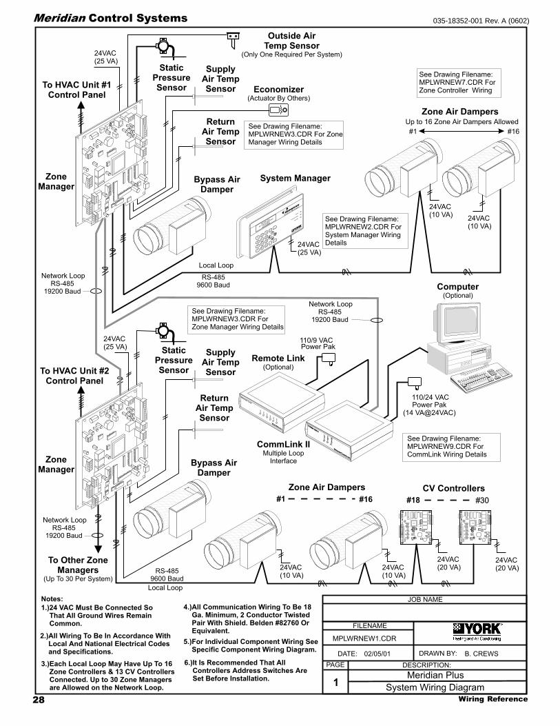
Meridian Control Systems 035-18352-001 Rev. A (0602)
To Other ZoneManagers
(Up To 30 Per System)
ZoneManager
ZoneManager
SupplyAir TempSensor
SupplyAir TempSensor
To HVAC Unit #2Control Panel
To HVAC Unit #1Control Panel
ReturnAir TempSensor
ReturnAir TempSensor
Bypass AirDamper
Bypass AirDamper
Economizer(Actuator By Others)
Outside AirTemp Sensor
(Only One Required Per System)
StaticPressureSensor
StaticPressureSensor
CV Controllers
Local Loop
Local Loop
Zone Air DampersUp to 16 Zone Air Dampers Allowed
Zone Air Dampers
#1
#18#1 #16
#16
System Manager
#30
24VAC(25 VA)
24VAC(20 VA)
24VAC(20 VA)24VAC
(10 VA)
24VAC(25 VA)
24VAC(25 VA)
24VAC(10 VA)
24VAC(10 VA)
24VAC(10 VA)
RELAY
OUTPUT
COM
1-3
OUT
OUT1
2
COM4-5
OUT
OUT
OUT
3
4
5
24VAC
GNDPWR
COMM
T
SHLD
LD4
REC.
12V
AIN1
2
3
4
5
GND
GND
AOUT
AIN
AIN
AIN
AIN
4-5
OUT
COMM
TEST
32K
8K
RAM EPROM
ADDRESS ADD
PRESSURE
SENSOR
485
COMM
R
YS101564
EWDOG
0-5
VDC
0-1
VDC
CPU
RELAY
OUTPUT
COM
1-3
OUT
OUT1
2
COM4-5
OUT
OUT
OUT
3
4
5
24VAC
GNDPWR
COMM
T
SHLD
LD4
REC.
12V
AIN1
2
3
4
5
GND
GND
AOUT
AIN
AIN
AIN
AIN
4-5
OUT
COMM
TEST
32K
8K
RAM EPROM
ADDRESS ADD
PRESSURE
SENSOR
485
COMM
R
YS101564
EWDOG
0-5
VDC
0-1
VDC
CPU
See Drawing Filename:MPLWRNEW3.CDR For ZoneManager Wiring Details
See Drawing Filename:MPLWRNEW3.CDR ForZone Manager Wiring Details
See Drawing Filename:MPLWRNEW9.CDR ForCommLink Wiring Details
See Drawing Filename:MPLWRNEW2.CDR ForSystem Manager WiringDetails
See Drawing Filename:MPLWRNEW7.CDR ForZone Controller Wiring
Computer(Optional)
CommLink IIMultiple LoopInterface
RS-48519200 Baud
RS-48519200 Baud
RS-48519200 Baud
RS-4859600 Baud
RS-4859600 Baud
110/24 VAC
Network Loop
Network Loop
Network Loop
Power Pak(14 VA@24VAC)
W
C
LI
ATTMASTER
ONTRO
S,NC
W
C
LI
ATTMASTER
ONTRO
S,NC
COMMLINKII
COMMLINKII
L
C
M
M
O
O
O
O
M
D
P
PE
Notes:
1.)24 VAC Must Be Connected SoThat All Ground Wires RemainCommon.
3.)Each Local Loop May Have Up To 16Zone Controllers & 13 CV ControllersConnected. Up to 30 Zone Managersare Allowed on the Network Loop.
4.)All Communication Wiring To Be 18Ga. Minimum, 2 Conductor TwistedPair With Shield. Belden #82760 OrEquivalent.
5.)For Individual Component Wiring SeeSpecific Component Wiring Diagram.
6.)It Is Recommended That AllControllers Address Switches AreSet Before Installation.
2.)All Wiring To Be In Accordance WithLocal And National Electrical Codesand Specifications.
FILENAME
DATE: B. CREWS
DESCRIPTION:PAGE
DRAWN BY:
System Wiring Diagram1
JOB NAME
02/05/01
MPLWRNEW1.CDR
Meridian Plus
Remote Link(Optional)
110/9 VACPower Pak
Remote
Link
C
O
N
T
R
O
L
S
SIG
DET
RDY
SND
REC
PWR
Clear WindowArea
65
4
DEC
7MINU
S
0
CLEA
R98
1
32
MEN
U
Override
Communication
ENTER
ESC
Alarm
System
Manager
-
Heatingand Air C
onditioning
®

29Wiring Reference
Meridian Control Systems035-18352-001 Rev. A (0602)
Notes:
FILENAME
DATE: B. CREWS
DESCRIPTION:PAGE
DRAWN BY:
System Manager Wiring2
JOB NAME1.)24 VAC Must Be Connected So
That All Ground Wires RemainCommon.
2.)All Wiring To Be In AccordanceWith Local And National ElectricalCodes And Specifications.
3.) All Communication Wiring To Be2 Conductor Twisted Pair WithShield. Use Belden #82760 OrEquivalent.
06/11/01
MPLWRNEW2.CDR
Meridian Plus
The Ideal Recommended Location For The System Manager Is As TheFirst Device On The Local Loop, (Connect To MiniLink Local Loop Terminals)Although The System Manager May Be Connected To Any Local Loop AtAny Point On The Local Loop.The System Manager Will Not Operate Correctly If Attached To The Network Loop.
DO NOT CONNECT TO THE NETWORK LOOP.
System Manager
654
DEC
7
MINUS0 CLEAR
98
1 32 MENU
Override
Communication
ENTER
ESC
Alarm
To MiniLink, Or Next DeviceOn Local Loop
Line Voltage
See Note 1
See Note 324VAC
GND
Required VA For TransformerSystem Manager = 25VA Max.
MADE IN
THE USA
EP
RO
M
1000uF10v
YS101806 REV. 1
DSPY1
UNIVERSAL SMART DISP. UNIT
SYSTEM MANAGER
SERIAL # :
U13SERIAL #
1000uF10v
C9
470uF50v
D2
PC
B80C
552-5
-16W
P
442860=2/5
DfD
9722V
7Y
PH
ILIP
S
CX
13
LD8
CX
9
SS0017
vx.xx 1234
V62C518256L-70P
U9
U8
LD7
RN
1
LD6
U7
CX7
74H
C573
LD5
LD4
74HC573
CX
8
RN2
X2
CX
4
470uF50v
TB
2
GND
24VAC
R10
75176
RS-485
COMM
U12
CX
12
RA
M
SC1
T
TB
1
SHLD
C7
C11
L1
C4
R
D6
8583
U6
CX6C3
D3
24C
128
U5
R7
VAR1
D4
PJ1
R3
U1
74HC259
LD3
LD2
LD1
R2
R1
EW
DO
G
PH
ILIP
S
U3
U2
CX
1
82B715CX5
CX
3
U3
DSPY1
R5
D1
R6
MC
34064A
C6
R11
9936 C8
R9
U10
U11
R8
R12
C5
74H
C923
CX10
P1
R4
RV1
C2
C1
X1

Wiring Reference30
Meridian Control Systems 035-18352-001 Rev. A (0602)
If The Actuator WiringInterface You Have OnYour System LooksDifferent From The OneShown Please SeePage 63 For CorrectWiring Information.
Zone Manager
Notes:
1.)24 VAC Must Be Connected SoThat All Ground Wires RemainCommon.
3.)All Communication Wiring To Be 18Ga. Minimum, 2 Conductor TwistedPair With Shield. Belden #82760 OrEquivalent.
5.)For Individual Component Wiring SeeSpecific Component Wiring Diagram.
6.)It Is Recommended That AllControllers Address Switches AreSet Before Installation.
2.)All Wiring To Be In Accordance WithLocal And National Electrical Codesand Specifications.
RS-485Communications To ZoneControllers, CV ControllersAnd/Or System Manager
Return Air Temp.Sensor
Supply Air Temp.Sensor
LineVoltage
HVACUnit
24VAC Only
Red
Blk
To Relief / Exhaust Fans
Grn
StaticPick-up
StaticPressureSensor
Splice AsRequired
LO HI
GND
24VAC
Belimo Actuator Wiring ShownConsult Factory For Other
Models Of Economizer ActuatorsSome Actuators Require IsolationTransformers In Order To PreventDamage To The Controller Board.
WARNING!
Use Extreme Care When WiringEconomizer Actuators
Never Connect Or DisconnectWiring With Power Applied!
Never Apply Power If TheGnd ( 1 Com ) Terminal On TheActuator Is Not Connected.See Note 1 &2
+
+
++
+
++
+ +
HEAT2
HEAT1
COOL2
COOL1
FAN
R
2
8C
SW1
16AB 24
ADD
LOCALLOOP
Local Loop
T
SH
RTB3
COMM
T
SH
R
32
16
8
4
1
2
MINILINK
R9
R10
R8
I CEXPPORT
PWR
V4
V3
CLOSE
OPEN
FDBK
REC
GND
GND
24VAC
AUX1
OPEN
K1
NETWORKLOOP
Network Loop RS-485
To Other ZoneManagers and/orCommLink onSystem
SH
R
T
CLOSE
K2
NE5090
ANALOGOUTPUTS
A2
G
TB2
A1
N.O.
EXHAUSTCONTACTS
GND
GND
AUX3
AUX2
7824
D25
U14
VR3
R40
ADJUST5.11V
C27
7812 C26
VR2
D1
D3
D4
D2
PJ1
PRESSURE
SENSORJACK
+5V
R7
OAT
RAT
+12V
SAT
ANALOGINPUTS
GND
SIG
T
R
SHIELD
T
R
SHIELD
Outdoor Air Temp.Sensor
(See Note 4)
Aux3ForcedOccupiedMode
Aux1EconomizerDisable
Aux2FilterAlarm
Auxiliary Inputs( Dry Contacts )
R
G
Y1
Y2
W1
W2
Economizer Actuator
133 IN-LB
AF24-SR
1 COM
2 +
3 Y1
4 Y2
5 UBELIMO
For Detailed ConnectionsAnd Slave WiringSee Bypass Actuator WiringDrawing Filename:MPLWRNEW4.CDR
See Drawing Filename:MPLWRNEW5.CDR ForAddress Switch Settings
Bypass Air DamperActuator
10
4.)Only One Outside Air Sensor IsRequired Per System. It May BeConnected To Any CV Controller OrZone Manager On The System. If AWetbulb Module Controller Is Used TheOA Sensor Must Be Connected To TheWetbulb Module.
FILENAME
DATE: B. THRALL
DESCRIPTION:PAGE
DRAWN BY:
Zone Manager Wiring3
JOB NAME
02/05/01
MPLWRNEW3.CDR
Meridian Plus
FROMZONE
CONTROLLER
BYPASSAND
SLAVEINTERFACE
YS101824
TOACTUATOR
OPEN
CLOSE
OPEN
GND
PJ1
PJ2LD2
LD1
CLOSE
TB
1T
B2
Bypass Interface Card
OPEN
CLOSE
FDBK
GND

31Wiring Reference
Meridian Control Systems035-18352-001 Rev. A (0602)
If The Actuator WiringInterface You Have OnYour System LooksDifferent From The OneShown Please SeePage 64 For CorrectWiring Information.
BYPASS ACTUATOR #3 (SLAVE)(WHEN USED) BYPASS ACTUATOR #2 (SLAVE)
BYPASS ACTUATOR #1(MASTER)
MODULAR CABLE
MODULARCABLE
MODULARCABLE
1 10 0
10
ZONE MANAGER BOARD
FROMZONE
CONTROLLER
BYPASSAND
SLAVEINTERFACE
YS101824
TOACTUATOR
OPEN
CLOSE
FDBK
OPEN
GND
GND
PJ1
PJ2LD2
LD1
OPEN
CLOSE
CLOSE
TB
1T
B2
FROMZONE
CONTROLLER
BYPASSAND
SLAVEINTERFACE
YS101824
TOACTUATOR
OPEN
CLOSE
FDBK
OPEN
GND
GND
PJ1
PJ2LD2
LD1
OPEN
CLOSE
CLOSE
TB
1T
B2
V4
V3
REC
CLOSE
OPENK1
K2
NETWORK
SH
R
T
NE5090
FDBK
GND
OPEN
CLOSE
NOT USED FORTHIS APPLICATION NOT USED FOR
THIS APPLICATION
NOT USED FORTHIS APPLICATION
FILENAME
DATE: B. CREWS
DESCRIPTION:PAGE
DRAWN BY:
Bypass -Slave Wiring4
JOB NAME
02/28/01
MPLWRNEW4.CDR
Meridian Plus
FROMZONE
CONTROLLE
R
BYPASSAND
SLAVEINTERFACE
YS101824
TOACTUATOR
OPEN
CLOSE
FDBK
OPEN
GND
GND
PJ1
PJ2 LD2
LD1
OPEN
CLOSE
CLOSE
TB
1T
B2
BYPASS ANDSLAVE INTERFACE CARD
BYPASS ANDSLAVE INTERFACE CARD
BYPASS ANDSLAVE INTERFACE CARD

Wiring Reference32
Meridian Control Systems 035-18352-001 Rev. A (0602)
Notes:
FILENAME
DATE: B. CREWS
DESCRIPTION:PAGE
DRAWN BY:
Zone Manager Address Switch Settings5
1632
8421
Caution!The MiniLinks Must Have Address Switches Set Between 1And 30 (Up To 30 MiniLinks (Mounted on Zone Managers)Are Allowed Per Auto-Zone Plus System). The MiniLinksShould Be Addressed In Consecutive Order Starting WithAddress #1. Address #1 Must Be Present On The Loop ForThe System To Function.
Address Switch Shown IsSet For Address 1
Address Switch Must Always Be SetTo Address 17 on Zone Manager Board
As Shown
Address Switch Shown IsSet For Address 4
Zone ManagerAddress Switch
MiniLinkAddress Switch
These Switches Must BeIn The OFF PositionAs Shown
These Switches Must BeIn The OFF PositionAs Shown
Caution:The Power To The Zone Manager Must BeRemoved And Reconnected After Changing TheMiniLink Or Zone Manager Address Switch SettingsIn Order For Any Changes To Take Effect.
Caution:Disconnect All Communication Loop Wiring FromThe Zone Manger Before Removing Power.Reconnect Power And Then ReconnectCommunication Loop Wiring To Zone Manager.
ADD
ADD
ADD
12
481632B
NET
ADD
All Zone Managers On System Must BeAddressed As 17
Network Switch As ShownMust Be ON
The Address For Each MiniLinkMust Be Unique To The Other MiniLinksOn The Network Loop. Loop #1 MiniLink
Should Be Addressed As #1Loop #2 MiniLink Should Be Addressed
As #2 Etc..
ADD
ADD
ADD
32
32
32B
BNET
NET
16
1616
8
88
4
4
4
1
1
1
2
2
2
OFF >
OFF
>
OFF
>
RockerDown
RockerDown
RockerDown
JOB NAME
02/28/01
MPLWRNEW5.CDR
Meridian Plus
HEAT2
HEAT1
COOL2
COOL1
FAN
R
LOCALLOOPT
SH
RTB3
COMM
T
SH
R
MINILINKV4
V3
CLOSE
OPEN
FDBK
GND
OPEN
K1
NETWORKLOOP
SH
R
T
CLOSE
K2
ANALOGOUTPUTS
A2
G
TB2
A1
Zone Manager Board(Under MiniLink Board)
MiniLink Address Switch Setting
Zone Manager Address Switch Setting
MiniLink Board(Mounted On Top Of Zone Manager Board)

33Wiring Reference
Meridian Control Systems035-18352-001 Rev. A (0602)
16
8421
Address Switch Shown IsSet For Address 18
Address Switch Shown IsSet For Address 28
ControllerAddress Switch
This Switch Must BeIn The ON PositionAs Shown
These Switches Should BeIn The OFF PositionAs Shown
ADDRESS ADD
ADDRESSADD
ADDRESSADD
The Address For Each ControllerMust Be Between 18 And 30 And BeUnique To The Other Controllers
On The Local Loop
Line Voltage
Line Voltage
See Note 1
See Note 1
Wx or Yx (Htg or Clg Stage x)
Wx or Yx (Htg or Clg Stage x)
Wx or Yx (Htg or Clg Stage x)
Wx or Yx (Htg or Clg Stage x)
G (Fan-On/Off)
R (24VAC)
Constant VolumeUnit Connections
CV Controller
R
SH
T
R
SH
T
R
SH
T
R
SH
T
All Comm Loop Wiring IsStraight Thru
Required VA For TransformerEach CV Controller = 20VA Max.
24VAC
24VAC
GND
GND
Mount In HVACUnit SupplyAir Duct
Auxiliary AlarmInput
Switch SuppliedBy Others
DischargeAir Temp.Sensor
Outside AirTemp. Sensor
AOUT
GND
GND
AIN5
AIN1AIN2AIN3AIN4
12V
GND
AUX
TMP
NORMAL
OVR
RELO
C
REMR
O
AW
COMM
REC.
LD4
T
R
SHLD
GND
24VAC
PWR
COMM
TEST
RELAYOUTPUTS
COM4-5
OUT1
OUT2
OUT3
OUT4
OUT5
COM1-3Room Sensor
Diagnostic Blink Code LED
RAM
EPROM
Local LoopRS-485
9600 Baud(See Note 3).
Connect ToNext Controller
And/OrMiniLink OnLocal Loop
Note:The Power To The CV Controller Must Be RemovedAnd Reconnected After Changing The AddressSwitch Settings In Order For Any Changes To TakeEffect.
Caution:Disconnect All Communication Loop WiringFrom The CV Controller Before Removing PowerFrom The CV Controller. Reconnect Power AndThen Reconnect Communication Loop Wiring.
ADDRESS ADD
Connection ToAUX Terminal is ReqdOnly When SensorIs Specified WithSlide Adjust Option
EconomizerActuator
(Belimo Shown)Consult Factory ForOther ManufacturersWiring Connections
Note:Up To 4 Stages Of Heating Or Cooling Or AnyCombination Of Each Is Allowed And ProgrammableVia The System Manager or ZoneView Software. If TheUnit Has Heat, Heating Stages Must Be Connected ToThe First Outputs in Consecutive Order And CoolingStages To The Remaining Outputs In Consecutive Order.
Outside AirTemp. Sensor(See Note 4)
Caution!CV Controllers Must Have Address Switches SetBetween 18 And 30 ( Up To 13 Units Per Local Loop ).
Note:The Power To The CV Controller Must Be RemovedAnd Reconnected After Changing The AddressSwitch Settings In Order For Any Changes To TakeEffect.
Caution:Disconnect All Communication Loop WiringFrom The CV Controller Before Removing PowerFrom The CV Controller. Reconnect Power AndThen Reconnect Communication Loop Wiring.
Notes:1.)24 VAC Must Be Connected So
That All Ground Wires RemainCommon.
4.)Only One Outside Air Sensor IsRequired Per System. It May BeConnected To Any CV Controller OrZone Manager On The System. If AWetbulb Module Controller Is Used TheOA Sensor Must Be Connected To TheWetbulb Module.
2.)All Wiring To Be In AccordanceWith Local And National ElectricalCodes And Specifications.
3.)All Communication Wiring To Be2 Conductor Twisted Pair WithShield. Use Belden #82760 OrEquivalent.
Y 3
+ 2
COM 1
FILENAME
DATE: B. CREWS
DESCRIPTION:PAGE
DRAWN BY:
CV Controller Wiring
JOB NAME
02/28/01
MPLWRNEW6.CDR
Meridian Plus6

Wiring Reference34
Meridian Control Systems 035-18352-001 Rev. A (0602)
Notes:
FILENAME
DATE: B. CREWS
DESCRIPTION:PAGE
DRAWN BY:
Zone Controller Wiring
Line Voltage
See Note 1
R
SH
T
R
SH
T
R
SH
T
R
SH
T
All Comm Loop Wiring IsStraight Thru
Required VA For TransformerEach Zone Controller = 10 VA Max.
(Includes Actuator)
24VAC
GND
GND
AUX
TMP
NORMAL
OVR
RELO
C
REMR
O
AW
1632TOKENNET
8421
Caution!Zone Controllers Must Have Address Switches Set Between1 And 16 ( Up To 16 Zone Controllers Per Local Loop ).
Room Sensor
Diagnostic Blink Code LED
Zone Actuator
Local LoopRS-485
9600 Baud(See Note 3).
Airflow Sensor (Optional)Only Used For PressureIndependent Applications
Connect ToNext ControllerAnd/Or ZoneManager OnLocal Loop
Address Switch Shown IsSet For Address 9
Address Switch Shown IsSet For Address 13
ControllerAddress Switch
This Switch Must BeIn The ON PositionAs Shown
Switches Labeled 32 AndToken Should Be In TheOFF Position As Shown
Note:The Power To The Zone Controller Must BeRemoved And Reconnected After Changing TheAddress Switch Settings In Order For Any ChangesTo Take Effect.
Caution:Disconnect All Communication Loop WiringFrom The Zone Controller Before Removing PowerFrom The Zone Controller. Reconnect Power AndThen Reconnect Communication Loop Wiring.
ADDRESS ADD
ADDRESSADD
ADDRESSADD
The Address For Each ControllerMust Be Between 1 And 16 And BeUnique To The Other Controllers
On The Local Loop
Connection To AUXTerminal Required OnlyWhen Sensor Is SpecifiedWith Slide Adjust Option
JOB NAME1.)24 VAC Must Be Connected SoThat All Ground Wires RemainCommon.
2.)All Wiring To Be In AccordanceWith Local And National ElectricalCodes And Specifications.
3.)AllCommunication Wiring To Be2 Conductor Twisted Pair WithShield. Use Belden #82760 OrEquivalent.
02/28/01
MPLWRNEW7.CDR
Meridian Plus7
10
FLOW
COMM
24VAC24VAC
GNDGND
AUX
REV.0
REV.0
YS101470
YS101470
F1F1
SHIELD
R
T
TEMP
GND
GND
AUX1
+VS
AUX2
C12
C12
3406334063VR1
VR1
TB4
TB4
IIGO GO
7824
7824
K2
K1
U7
U7
U5
U5
LD1
LD1
NET
POWER
SCANSCAN++L1L1
RECREC
++
LD2
LD2
LD3LD3
TB3
TB3
75176
CX10CX10
SW1
SW1
4488
32TOKEN
1616
ADDRESSON
EWDOG
1122
C6
C6
9346
9346
CX6
CX6
U6
U6
PJ1
PJ1
TB2
RV1
RV1
ADJ
VREF
CX9CX9
++
358
358
U9U9
TB1
TB1
RAMRAM
HC259
80C55280C552
EPROMEPROM
CX2CX2
16L816L8
ACTUATO
RACTUATO
REXPANSION
EXPANSION
U2
CX8
PJ3
HC573
HC573
U8
U4
32KCX4
U3CX3 CX1CX1
RAM8K
HiLo
Airflow

35Wiring Reference
Meridian Control Systems035-18352-001 Rev. A (0602)
If The Actuator WiringInterface You Have OnYour System LooksDifferent From The OneShown Please SeePage 65 For CorrectWiring Information.
SLAVED- ZONE ACTUATOR #2(WHEN USED) SLAVED-ZONE ACTUATOR #1
ZONE ACTUATOR #1(MASTER)
MODULAR CABLE
MODULAR CABLE
MODULARCABLE
MODULARCABLE
1 10 0
10
BYPASS ANDSLAVE INTERFACE CARD
BYPASS ANDSLAVE INTERFACE CARD
BYPASS ANDSLAVE INTERFACE CARD
ZONE CONTROLLER BOARD
FROMZONE
CONTROLLER
BYPASSAND
SLAVEINTERFACE
YS101824
TOACTUATOR
OPEN
CLOSE
FDBK
OPEN
GND
GND
PJ1
PJ2LD2
LD1
OPEN
CLOSE
CLOSE
TB
1T
B2
FROMZONE
CONTROLLER
BYPASSAND
SLAVEINTERFACE
YS101824
TOACTUATOR
OPEN
CLOSE
FDBK
OPEN
GND
GND
PJ1
PJ2LD2
LD1
OPEN
CLOSE
CLOSE
TB
1T
B2
NOT USED FORTHIS APPLICATION NOT USED FOR
THIS APPLICATION
FILENAME
DATE: B. CREWS
DESCRIPTION:PAGE
DRAWN BY:
Slaved-Zone Wiring8
JOB NAME
02/28/01
MPLWRNEW8.CDR
Meridian Plus
FROMZONE
CONTROLLE
R
BYPASSAND
SLAVEINTERFACE
YS101824
TOACTUATOR
OPEN
CLOSE
FDBK
OPEN
GND
GND
PJ1
PJ2 LD2
LD1
OPEN
CLOSE
CLOSE
TB
1T
B2PJ2PJ1
ACTUATOREXPANSION
Note:1.) A Slave Wiring Adapter consisting of a bypass & slave interface cardand modular cable is supplied with the Round Slaved-Zone Damper,Rectangular Slaved-Zone Damper Kit and the Slaved Zone Package. It isrequired when attaching slave actuator(s) to the master zone damper.The bypass & slave interface card should be mounted in the controlenclosure of the master zone damper. It is mounted by fastening theplastic snap-track to the control enclosure with sheet metal screws.Connect modular cables to the bypass and slave interface card and themaster zone actuator as shown.

Wiring Reference36
Meridian Control Systems 035-18352-001 Rev. A (0602)
Commlink II Communications Interface
(Jumper Set For Multiple Loop)
Caution: Use The “Molded Cable” ToConnect To The Computer (DCE) Connector.This Cable Is Only To Be Used To ConnectFrom The CommLink (DTE) Connection ToThe Modem (When Used).
Do Not
Caution:Disconnect All Communication Loop WiringFrom The CommLink Before Removing PowerFrom The CommLink. Reconnect Power And ThenReconnect Communication Loop Wiring.
Use 25 Pin Or 9 Pin Connector AsRequired By Available Serial (COM) PortOn Computer.
JOB NAME
Caution: Use The “25 Pin Or 9 Pin Cable” ToConnect To The Modem (DTE) Connector.. ThisCable Is Only To Be Used To Connect From TheCommLink (DCE) Connection To The Computer
Serial Port (COM) Connection.
Do Not
(When Used) Note:Place Jumper BetweenPins 1 & 2 for MultipleLoop Applications &Between Pins 2 & 3 forSingle Loop ApplicationsSee Note 4.
COMM DRIVER CHIP( U1 )PIN 1
MULTI
SINGLE
123
CommLink Jumper Switch SettingsNotes:
FILENAME
DATE: B. CREWS
DESCRIPTION:PAGE
DRAWN BY:
CommLink II Wiring9
R
SH
T
R
SH
T
R
SH
T
R
SH
T
All Communication LoopWiring Is Straight Through
Connect To First ZoneManager On Network Loop
Network LoopRS-485
19200 Baud(See Note 3).
Line Voltage
See Note 1
24VAC
Required VA For TransformerCommLink = 14VA Max.
CommLink Is Supplied With 110/24VAC Power Supply.If Desired A Transformer (By Others)
May Be Wired To The CommLink Instead
Molded Modem Cable.Supplied With CommLink
(DTE)MODEM COMPUTER
(DCE)
GT R
4 Piece ComputerCable Kit.Supplied WithCommLink
Connect To Modem .Only
9Pin
Female
9 PinFemale
25 PinFemale
9Pin
Female
120/24 VacTransformer
25 PinMale
Connect Supplied RJ12 Modular Phone CableTo Supplied 9 Pin Or 25 Pin Connector As ReqdBy Your Computer Com Port Connection
1.)24 VAC Must Be Connected SoThat All Ground Wires RemainCommon.
2.)All Wiring To Be In AccordanceWith Local And National ElectricalCodes And Specifications.
3.)All Communication Wiring To Be2 Conductor Twisted Pair WithShield. Use Belden #82760 OrEquivalent.
02/28/01
MPLWRNEW9.CDR
Meridian Plus
4.)CommLink Is Shipped With TheJumper In The Multiple LoopConfiguration, So It Is Not NecessaryTo Move It For A Plus System.
485 LOOPPOWER24V
GND

37Wiring Reference
Meridian Control Systems035-18352-001 Rev. A (0602)
AdAdAdAdAdd-On Ded-On Ded-On Ded-On Ded-On Devicesvicesvicesvicesvices
WWWWWiring Diairing Diairing Diairing Diairing Diagggggrrrrramsamsamsamsams

Wiring Reference38
Meridian Control Systems 035-18352-001 Rev. A (0602)
12V
T4
T3
T1
LINE
VOLTAGE
250OHM
RESISTOR
(ShippedWithSensor)
TobeInstalledBetween
AIN2andGND
Note: Terminal That Is Labeled 12V on theTerminal Block Has Been Electrically Modified
and Is Actually 24 VDC
When WetbulbEconomizer
Module is UsedOutdoor Air
Sensor Must BeConnected As
Shown
T2 AIN1
2
3
4
5
GND
GND
AIN
AIN
AIN
AIN
RELAYOUTPUT
COM1-3
OUT
OUT1
2
COM4-5
OUT
OUT
OUT
3
4
5
24VAC 24VAC
GNDGND
PWR
COMM
TT
SHLDSHLD
LD4
REC.
AOUT
4-5
OUT
COMM
TEST
32K
8K
RAM EPROM
ADDRESS ADD
PRESSURESENSOR
485COMM
RR
YS101564
EWDOG
0-5
VDC
0-1
VDC
PU1
PU2
PU3
PU4
PU5
The Pull-up Resistor (Pu2)Must Be Removed
When Using A 4-20ma Device
DIGITAL OUTPUTSNOT USED
4-20 mAHumidity Sensor
10 kohmOutdoor AirSensor
FILENAME
DATE: B. CREWS
DESCRIPTION:PAGE
DRAWN BY:
Wetbulb Module Wiring1
JOB NAME
06/06/01
MWBWIR1.CDR
2ZOH0047004524
Wetbulb Module Address Switch Setting
Local Loop9600 Baud
See Note 1
16
8421
Caution!Wetbulb Controller Must Have AddressSwitch Set Between 18 And 30 On theMeridian Plus SystemAnd Between 1 to 30 On The CV or CV-EXSystems
Caution!Wetbulb Controller Must Have Address Switch SetBetween 18 And 30 On the Meridian Plus SystemAnd Between 1 to 30 On The CV or CV-EX Systems.
Address Switch Shown IsSet For Address 9
Address Switch Shown IsSet For Address 28
ControllerAddress Switch
This Switch Must BeIn The ON PositionAs Shown
These Switches Should BeIn The OFF PositionAs Shown
Note:The Power To The Wetbulb Controller MustBe Removed And Reconnected AfterChanging The Address Switch Settings InOrder For Any Changes To Take Effect.
Caution:Disconnect All Communication Loop WiringFrom The Wetbulb Controller BeforeRemoving Power From The WetbulbController. Reconnect Power And ThenReconnect Communication Loop Wiring.
ADDRESS ADD
ADDRESSADD
ADDRESSADD
1.)24 VAC Must Be Connected So That AllGround Wires Remain Common.
2.)All Wiring To Be In Accordance With Local AndNational Electrical Codes And Specifications.
3.)AllCommunication Wiring To Be 2 Conductor TwistedPair With Shield. Use Belden #82760 Or Equivalent.
Required VA ForTransformer
For Wetbulb Controller= 20VA Max.
Suggested Wetbulb Economizer SettingsThe Wetbulb Temperature value is 65 F forEconomizer Enable. The Mechanical CoolingLockout setpoint is 60 F. The Economizer Enable WetbulbTemperature should be set lower than the MechanicalCooling Lockout Setpoint. If you allow the Economizer WetbulbEnable Setpoint to drop below the Mechanical Cooling LockoutSetpoint the unit can enter a mode where cooling is required inthe space but both the mechanical cooling and the economizerare disabled at the same time. Basically, you can economicallycool outside air that is below 78 F if the wetbulb temperature is65 F or lower. In the case of the Meridian system, theEconomizer is always considered the first stage of cooling. Ifthe outside air is above 78 but the wetbulb temperature is stillenabling the economizer, the outside air dampers willimmediately move to the full 100% open position. This allowsthe mechanical cooling to activate after a short two minutedelay and begin cooling the low moisture outside air rather thanthe high moisture content of the return air.
If the wetbulb temperature rises above the Economizer EnableSetpoint while the economizer is currently active and themechanical cooling is active, the economizer will be returned toits minimum position and the unit will maintain strictlymechanical cooling.
suggested
suggested
never
Notes:Note:Set-up, Programming AndMonitoring Of The Wetbulb ModuleRequires The Use Of A PersonalComputer And MeridianViewSoftware.
WM PN: OE330Y-WBF
Wetbulb Controller

39Wiring Reference
Meridian Control Systems035-18352-001 Rev. A (0602)
Relay Output(s) ToDevice(s) AsRequiredBy Application
Analog Input(s)And/Or DigitalInput(s) FromDevicesAs Required ByApplication
Analog OutputTo Device (WhenUsed)(0-10 VDC)
Notes:
FILENAME
DATE: B. CREWS
DESCRIPTION:PAGE
DRAWN BY:
GPC Controller Wiring
GPC Controller 2ZGP004700124
Caution!GPC Controllers Must Have Address Switches SetBetween 1 And 30 When Used With CV or CV-EXSystems. Meridian Plus Systems and Basic SystemsRequire That The Address Switches Be Set Between 18To 30.
Note:The Power To The GPC Controller Must BeRemoved And Reconnected After Changing TheAddress Switch Settings In Order For Any ChangesTo Take Effect.
Caution:Disconnect All Communication Loop WiringFrom The GPC Controller Before Removing PowerFrom The GPC Controller. Reconnect Power AndThen Reconnect Communication Loop Wiring.
JOB NAME1.)24 VAC Must Be Connected SoThat All Ground Wires RemainCommon.
2.)All Wiring To Be In AccordanceWith Local And National ElectricalCodes And Specifications.
4.)Part Number Listed Is ForFahrenheit Temperatures, IfCelsius is Required, The PartNumber is 2ZGP004700224.
06/06/01
MGPCALL2.CDR
2ZGP0047001241
Note:Set-up, Programming And Monitoring Of The GeneralPurpose Controller Requires The Use Of A PersonalComputer And MeridianView Software.
12V
LINE
VOLTAGE
AIN1
2
3
4
5
GND
GND
AIN
AIN
AIN
AIN
RELAYOUTPUT
COM1-3
OUT
OUT1
2
COM4-5
OUT
OUT
OUT
3
4
5
24VAC 24VAC
GNDGND
PWR
COMM
TT
SHLDSHLD
LD4
REC.
AOUT
4-5
OUT
COMM
TEST
32K
8K
RAM EPROM
ADDRESS ADD
PRESSURESENSOR
485COMM
RR
YS101564
EWDOG
0-5
VDC
0-1
VDC
PU1
PU2
PU3
PU4
PU5
GPC Controller Address Switch Setting
Local Loop9600 Baud
16
8421
Caution!GPC Controller Must Have Address Switch SetBetween 18 And 30 On the Meridian Plus SystemAnd Between 1 to 30 On The CV or CV-EX Systems.
Address Switch Shown IsSet For Address 9
Address Switch Shown IsSet For Address 28
ControllerAddress Switch
This Switch Must BeIn The ON PositionAs Shown
These Switches Should BeIn The OFF PositionAs Shown
ADDRESS ADD
ADDRESSADD
ADDRESSADD
Required VA ForTransformer
For Wetbulb Controller= 20VA Max.
WM PN: OE330Y-GPCF
3.)AllCommunication Wiring To Be2 Conductor Twisted Pair WithShield. Use Belden #82760 OrEquivalent.

Wiring Reference40
Meridian Control Systems 035-18352-001 Rev. A (0602)
WM PN: OE310Y-21-OSSF
MOPSTSCD1.CDR
FILENAME
JOB NAME
DESCRIPTION:
2ZOS004700124
DATE DRAWN:
PAGE
1
05/17/01 B. CREWSDRAWN BY:
Note:All Circuit Board Contacts Are N.O.All Contacts Are Rated For 2 Amps @24VAC Pilot Duty OnlyDo Not Apply Any Voltage Greater Than24VAC
Equipment Circuit 1
Equipment Circuit 2
Equipment Circuit 3
Equipment Circuit 4
Equipment Circuit 5
Equipment Circuit 6
Equipment Circuit 7
Line Voltage
C1
C2
C3
C4
C5
C6
C7
Equipment Contactors OrPilot Duty Relays(By Others)
Caution: If Equipment Contactor CoilCurrent Draw Is More Than 2 Amps And/OrDoes Not Use A 24VAC Coil, A Pilot DutyRelay That Has A Current Draw Of LessThan 2 Amps @ 24VAC Must Be Used ToEnergize The Equipment Contactor. ASeparate Transformer Rated For The TotalPilot Relay Current Draw Must Always BeUsed To Power The Circuit.
24V
GND
Note:Set-up, Programming And Monitoring Of The OptimalStart Scheduler Requires The Use Of A PersonalComputer And MeridianView Software.
1.)24 VAC Must Be Connected SoThat All Ground Wires RemainCommon.
3.)All Communication Wiring To Be 18Ga. Minimum, 2 Conductor TwistedPair With Shield. Belden #82760 OrEquivalent.
4.)It Is Recommended That AllControllers Address Switches AreSet Before Installation.
2.)All Wiring To Be In Accordance WithLocal And National Electrical Codesand Specifications.
Local Loop RS-485Communications To ZoneControllers, CV ControllersAnd/Or System Manager
EPROM
RAM
PAL
PIN 1PIN 1
PIN 1PIN 1
CPU
+V
+V
1
3
45678GG
2
ANALOGINPUTS
GND
SIG
+5V
ANALOGOUTPUTS
A1A2
G
T
SH
R
GND
24VAC
Optimal Start Scheduler2ZOS004700124
T
SHR
K1
K2
K3
K4
K5
K6
K7
Momentary Pushbuttons(Optional)Direct Control Of Equipment
(Optional)Override Circuit Schedule #1
Override Circuit Schedule #2
Override Circuit Schedule #3
Override Circuit Schedule #4
Override Circuit Schedule #5
Override Circuit Schedule #6
Override Circuit Schedule #7
Line Voltage
See Note 1
16 8 4 2 1
Address Switch Shown IsSet For Address 1
Address Switch Shown IsSet For Address 13
ControllerAddress Switch
This Switch Must BeIn The ON PositionAs Shown
These Switches Should BeIn The OFF PositionAs Shown
ADD
ADDADD
The Address For Each ControllerMust Be Unique To The Other Controllers
On The Local Loop
Required VA For TransformerEach Controller = 25VA Max.
Optimal Start Scheduler Wiring
Caution!Controller Must Have Address Switch Set Between18 And 30 On the Meridian Plus SystemAnd Between 1 to 30 On The CV or CV-EX Systems.
NOTE: The part number listed is for temperaturereading in Fahrenheit, if Celsius is required, thepart number is 2ZOS004700224.

41Wiring Reference
Meridian Control Systems035-18352-001 Rev. A (0602)
WM PN: OE310Y-21-LP
MLITPNLST.CDR
FILENAME
JOB NAME
DESCRIPTION:
Lighting Panel Controller Wiring
2ZLC004700124
DATE DRAWN:
PAGE
1
05/17/01 B. CREWSDRAWN BY:
1.)24 VAC Must Be Connected SoThat All Ground Wires RemainCommon.
3.)All Communication Wiring To Be 18Ga. Minimum, 2 Conductor TwistedPair With Shield. Belden #82760 OrEquivalent.
4.)It Is Recommended That AllControllers Address Switches AreSet Before Installation.
2.)All Wiring To Be In Accordance WithLocal And National Electrical Codesand Specifications.
Local Loop RS-485Communications To ZoneControllers, CV ControllersAnd/Or System Manager
Note:All Circuit Board Contacts Are N.O.All Contacts Are Rated For 2 Amps @24VAC Pilot Duty OnlyDo Not Apply Any Voltage Greater Than24VAC
EPROM
RAM
PAL
PIN 1PIN 1
PIN 1PIN 1
CPU
+V
+V
1
3
45678GG
2
ANALOGINPUTS
GND
SIG
+5V
ANALOGOUTPUTS
A1A2
G
T
SH
R
GND
24VAC
Lighting Panel Controller2ZLC004700124
Light Circuit 1
Light Circuit 2
Light Circuit 3
Light Circuit 4
Light Circuit 5
Light Circuit 6
Light Circuit 7
T
SHR
K1
K2
K3
K4
K5
K6
K7
Light Sensor (Optional) 2ZAS004700224
Momentary Pushbuttons(Optional)
Override Circuit #1
Override Circuit #2
Override Circuit #5
Override Circuit #3
Override Circuit #6
Override Circuit #4
Override Circuit #7
Line Voltage
Line Voltage
See Note 1
16 8 4 2 1
Address Switch Shown IsSet For Address 1
Address Switch Shown IsSet For Address 13
ControllerAddress Switch
This Switch Must BeIn The ON PositionAs Shown
These Switches Should BeIn The OFF PositionAs Shown
ADD
ADDADD
The Address For Each ControllerMust Be Unique To The Other Controllers
On The Local Loop
Required VA For TransformerEach Controller = 25VA Max.
C1
C2
C3
C4
C5
C6
C7
Lighting Contactors OrPilot Duty Relays(By Others)
All Lighting ContactorsMust Be Wired For N.C.Operation So That SystemFails To Lights On Mode.
Caution: If Lighting Contactor Coil CurrentDraw Is More Than 2 Amps And/Or DoesNot Use A 24VAC Coil, A Pilot Duty RelayThat Has A Current Draw Of Less Than 2Amps @ 24VAC Must Be Used To EnergizeThe Lighting Contactor. A SeparateTransformer Rated For The Total LightingContactor(s)Or Pilot Relay Current DrawMust Always Be Used To Power The Circuit.
24V
GND
Note:Set-up, Programming And Monitoring Of The LightingPanel Controller Requires The Use Of A PersonalComputer And MeridianView Software.
Caution!Controller Must Have Address Switch Set Between18 And 30 On the Meridian Plus SystemAnd Between 1 to 30 On The CV or CV-EX Systems.

Wiring Reference42
Meridian Control Systems 035-18352-001 Rev. A (0602)
WM PN: OE310Y-21-LP
MLGTPNLGE.CDR
FILENAME
JOB NAME
DESCRIPTION:
GE Latching Relay Wiring
2ZLC004700124 Lighting Panel Controller
DATE DRAWN:
PAGE
1
05/17/01 B. CREWSDRAWN BY:
Note:Set-up, ProgrammingAnd Monitoring OfThe Lighting PanelController RequiresThe Use Of APersonal ComputerAnd MeridianViewSoftware.
1.)24 VAC Must Be Connected SoThat All Ground Wires RemainCommon.
3.)All Communication Wiring To Be 18Ga. Minimum, 2 Conductor TwistedPair With Shield. Belden #82760 OrEquivalent.
2.)All Wiring To Be In Accordance WithLocal And National Electrical Codesand Specifications.
Local Loop RS-485Communications To Zone
Controllers, CVControllers
And/Or System Manager
Ribbon Connector
Relay Expansion Board2ZEB004701024
Ground
24V
All switches(1 thru 4)must be in the“ON” position
EPROM
RAM
PAL
PIN 1PIN 1
PIN 1PIN 1
CPU
+V
+V
1
3
45678GG
2
ANALOGINPUTS
GND
SIG
+5V
ANALOGOUTPUTS
A1A2
G
T
SH
R
GND
24VAC
Lighting Panel Controller2ZLC004700124
Light Circuit 1
Light Circuit 2
Light Circuit 1
Light Circuit 2
Light Circuit 3
Light Circuit 3
Light Circuit 4
Light Circuit 4
Light Circuit 5
Light Circuit 5
Light Circuit 6
Light Circuit 6
Light Circuit 7
Light Circuit 7
T
SHR
ON
OFF
24VAC
GE Lighting Relay- Circuit #1(By Others)
Typical Wiring Shown For Circuit #1All Other Circuits Are To Be WiredIdentically. Up to 7 Lighting Circuits MayBe Wired To Each Lighting Panel Controller.
K1
R1
R2
R3
R4
R5
R6
R7
R8
K2
K3
K4
K5
K6
K7
Light Sensor(Optional)
Line Voltage
Line Voltage
See Note 1
16 8 4 2 1
Address Switch Shown IsSet For Address 1
Address Switch Shown IsSet For Address 13
ControllerAddress Switch
This Switch Must BeIn The ON PositionAs Shown
These Switches Should BeIn The OFF PositionAs Shown
ADD
ADDADD
The Address For Each ControllerMust Be Unique To The Other Controllers
On The Local Loop
Required VA For TransformerEach Controller = 25VA Max.
Momentary Pushbuttons(Optional)
Override Circuit #1
Override Circuit #2
Override Circuit #5
Override Circuit #3
Override Circuit #6
Override Circuit #4
Override Circuit #7
Caution: If Lighting Contactor Coil Current Draw Is More Than 2Amps And/Or Does Not Use A 24VAC Coil, A Pilot Duty RelayThat Has A Current Draw Of Less Than 2 Amps @ 24VAC MustBe Used To Energize The Lighting Contactor. A SeparateTransformer Rated For The Total Lighting Contactor(s) Or PilotRelay Current Draw Must Always Be Used To Power The Circuit.
Note:All Circuit BoardContacts Are N.O.All Contacts AreRated For 2 Amps@ 24VAC PilotDuty OnlyDo Not Apply AnyVoltage GreaterThan 24VAC
Caution!Controller Must Have Address Switch Set Between18 And 30 On the Meridian Plus SystemAnd Between 1 to 30 On The CV or CV-EX Systems.

43Wiring Reference
Meridian Control Systems035-18352-001 Rev. A (0602)
MiscellaneousMiscellaneousMiscellaneousMiscellaneousMiscellaneous
DiaDiaDiaDiaDiagggggrrrrramsamsamsamsams

Wiring Reference44
Meridian Control Systems 035-18352-001 Rev. A (0602)
Notes:
FILENAME
DATE: B. CREWS
DESCRIPTION:PAGE
DRAWN BY:
CV-C Controller Wiring
Line Voltage
See Note 1
R
SH
T
R
SH
T
R
SH
T
R
SH
T
All Comm Loop Wiring IsStraight Thru
Required VA For TransformerEach CV-C Controller = 20VA Max.
24VAC
GND
16
8421
Caution!CV-C Controllers Must Have Address Switches Set Between 1And 30 When Used With CV or CV-EX Systems. Auto-ZonePlus Systems Require That The Address Switches Be SetBetween 18 And 30.
Local Loop RS-4859600 Baud(See Note 3).
Connect To Next Controller And/OrMiniLink On Local Loop
Address Switch Shown IsSet For Address 1
Address Switch Shown IsSet For Address 13
ControllerAddress Switch
This Switch Must BeIn The ON PositionAs Shown
These Switches Should BeIn The OFF PositionAs Shown
Note:The Power To The CV-C Controller Must Be Removed AndReconnected After Changing The Address Switch Settings In OrderFor Any Changes To Take Effect.
Caution:Disconnect All Communication Loop Wiring From The CV-C ControllerBefore Removing Power From The CV-C Controller. Reconnect PowerAnd Then Reconnect Communication Loop Wiring.
ADDRESS ADD
ADDRESSADD
ADDRESSADD
The Address For Each ControllerMust Be Unique To The Other Controllers
On The Local Loop
JOB NAME
1.)24 VAC Must Be Connected SoThat All Ground Wires RemainCommon.
2.)All Wiring To Be In AccordanceWith Local And National ElectricalCodes And Specifications.
3.)AllCommunication Wiring To Be2 Conductor Twisted Pair WithShield. Use Belden #82760 OrEquivalent.
06/07/01
MCVCWIR1.CDR
2ZRC0047003241
Note:Set-up, Programming And Monitoring Of The CV-C Controller Requires TheUse Of A Personal Computer And ZoneView AZ Software.
EXPANSION
SENSORPRESSURE
GND
7AIN
AOUT2
AOUT1
AIN
GND
GND5
AIN
AIN
AIN
4
3
2
T'STAT
24VAC
NETWORK
16
TOKEN
32
8
4
GND
AIN1
12V
INPUTS
R
SHLD
T
COMM
1
2
YS101718TUC5R PLUS
COM1-3
R5
COM4-5
R4
R3
R2
R1 R - Fan ON/OFF Only
GND
AUX
TMP
NORMAL
OVR
RELO
C
REMR
O
AW
Room Sensor
Connection ToAUX Terminal is ReqdOnly When SensorIs Specified WithSlide Adjust Option
AIN2 Thru AIN5 & AIN7 May Be UserConfigured For The Following:0 - Not Used ( Nothing connected to this input)1 - Slide Offset
(Requires Flush Mount Wall Sensor)2 - Supply Air Temperature3 - Return Air Temperature4 - Mixed Air Temperature5 - Outdoor Air Temperature(Will broadcast to ALL other controllers)
6 - Humidity Sensor (4-20 mA scaling)7 - Humidity Sensor (0-5 VDC scaling)8 - CO² Sensor (4-20 mA scaling)9 - CO² Sensor (0-5 VDC scaling)10- Relief Pressure Sensor(Requires 0-5 VDC ±0.3" WG Sensor)
11 - Dirty Filter Contact (Normally Open)12 - Alarm Contact (Normally Open)13- Alarm Contact (Normally Closed)14- Fan Status Contact (Normally Open)
AIN6 (Phone Jack) Can Only Be ConfiguredFor An Airflow Sensor And Is Used ForStatus or To Verify Fan Operation Only
Relay Outputs R2 Thru R5 May Be UserConfigured For The Following:0 - Not Used (Nothing connected to thisoutput )1 - Heating Stage2 - Cooling Stage3 - Humidifier Enable4 - De-Humidifier Enable5 - Scheduled Relay from Internal Schedule6 - Scheduled Relay from External Schedule(Only 1 Available!)
AOUT1 & AOUT2 May Be User Configured ForThe Following:0 - Not Used (Nothing connected to this output)1 - Economizer
(Requires Supply or Mixed Air Sensor2 - Relief Fan VFD Signal
(Requires Relief Pressure Sensor)3 - Chilled Water Valve(Requires Supply Sensor)
4 - Hot Water Valve (Requires Supply Sensor)5 - Humidification / De-Humidification(Requires Humidity Sensor)
Note: All Temperature Sensors Must Be Thermistor Type IIIWhich Provide 10K Ohms Resistance @77 Deg. F
CV- C Controller 2ZRC004700324
WM PN: OE745Y-F
NOTE: The part number listed is for temperaturereading in Fahrenheit, if Celsius is required, thepart number is 2ZRC004703024.

45Wiring Reference
Meridian Control Systems035-18352-001 Rev. A (0602)
Notes:
FILENAME
DATE: B. CREWS
DESCRIPTION:PAGE
DRAWN BY:
CV-C Relay Expansion Board Wiring
Line Voltage
Line Voltage
See Note 1
See Note 1
Required VA For TransformerEach CV-C Controller = 20VA Max.
Required VA For TransformerRelay Expansion Board = 20VA Max.
24VAC
24VAC
GND
GND
Caution!Relay Expansion Board Must Have Address Switches Set AsShown Or The Board Will Not Function.
Caution:Disconnect The Modular Cable Between The CV-C Controller And TheRelay Expansion Board Before Removing Power From The RelayExpansion Board. Reconnect Power And Then Reconnect The ModularCable Between The CV-C Controller And The Relay Expansion Board.
JOB NAME
1.)24 VAC Must Be Connected SoThat All Ground Wires RemainCommon.
2.)All Wiring To Be In AccordanceWith Local And National ElectricalCodes And Specifications.
07/08/99
MCVCREXP1.CDR
Meridian1
Note:Set-up, Programming And Monitoring Of The CV-C Controller Requires TheUse Of A Personal Computer And MeridianView AZ Software.
EXPANSION
SENSORPRESSURE
T'STAT
24VAC
GND
Relay Outputs R6 Thru R13 May Be UserConfigured For The Following:0 - Not Used (Nothing connected to thisoutput )1 - Heating Stage2 - Cooling Stage3 - Humidifier Enable4 - De-Humidifier Enable5 - Scheduled Relay from Internal Schedule6 - Scheduled Relay from External Schedule(Only 1 Available!)
CV- C Controller
Relay Expansion Board
EXPANSION PORT
24VAC
IN OUT
COM
Connect Expansion Boardto CV-C Controllerwith Modular Cable
Not Used
POWER
U4
U5
U3
U1
RELAY 1
RELAY 2
RELAY 3
ADDRESS
RELAY 4
RELAY 5
RELAY 6
RELAY 7
RELAY 8
N.O.CONTACTS
1-8
RELAYCOMMONS9,10
Warning:If One Transformer Is Used To Power The CV-C Controller And TheRelay Expansion Board, Polarity Must Be Strictly Observed. If ThePolarity Is Reversed, Serious Damage To Both Boards Will Result.

Wiring Reference46
Meridian Control Systems 035-18352-001 Rev. A (0602)
Notes:
FILENAME
DATE: B. CREWS
DESCRIPTION:PAGE
DRAWN BY:
Line Voltage
See Note 1
R
SH
T
R
SH
T
R
SH
T
R
SH
T
All Comm Loop Wiring IsStraight Thru
Required VA For TransformerEach Zone Controller = 10 VA Max.
24VAC
GND
GND
AUX
TMP
NORMAL
OVR
RELO
C
REMR
O
AW
1632TOKENNET
8421
Caution!Controllers Must Have Address Switches Set Between 1And 29 Up To 16 Zone Controllers Per Local Loop ).
Room Sensor
Diagnostic Blink Code LED
Local LoopRS-485
9600 Baud(See Note 3). Connect To
Next ControllerAnd/Or ZoneManager OnLocal Loop
Address Switch Shown IsSet For Address 9
Address Switch Shown IsSet For Address 13
ControllerAddress Switch
This Switch Must BeIn The ON PositionAs Shown
Switches Labeled 32 AndToken Should Be In TheOFF Position As Shown
Note:The Power To The Zone Controller Must BeRemoved And Reconnected After Changing TheAddress Switch Settings In Order For Any ChangesTo Take Effect.
Caution:Disconnect All Communication Loop WiringFrom The Zone Controller Before Removing PowerFrom The Zone Controller. Reconnect Power AndThen Reconnect Communication Loop Wiring.
ADDRESS ADD
ADDRESSADD
ADDRESSADD
The Address For Each ControllerMust Be Between 1 And ?? And BeUnique To The Other Controllers
On The Local Loop
Connection To AUXTerminal Required OnlyWhen Sensor Is SpecifiedWith Slide Adjust Option
JOB NAME1.)24 VAC Must Be Connected SoThat All Ground Wires RemainCommon.
2.)All Wiring To Be In AccordanceWith Local And National ElectricalCodes And Specifications.
3.)All Communication Wiring To Be2 Conductor Twisted Pair WithShield. Use Belden #82760 OrEquivalent.
01/08/01
MZCRHT1STG1A.CDR
Zone Relay Expansion Board Wiring1
10
FLOW
COMM
24VAC24VAC
GNDGND
AUX
REV.0
REV.0
YS101470
YS101470
F1F1
SHIELD
R
T
TEMP
GND
GND
AUX1
+VS
AUX2
C12
C12
34063VR1
VR1
TB4
TB4
IIGO GO
7824
7824
K2
K1
U7
U7
U5
U5
LD1
LD1
NET
POWER
SCANSCAN++L1L1
RECREC
++
LD2
LD2
LD3LD3
TB3
TB3
75176
CX10CX10
SW1
SW1
4488
32TOKEN
1616
ADDRESSON
EWDOG
1122
C6
C6
9346
9346
CX6
CX6
U6
U6
PJ1
PJ1
TB2
RV1
RV1
ADJ
VREF
CX9CX9
++
358
358
U9U9
TB1
TB1
RAMRAM
HC259
80C55280C552
EPROMEPROM
CX2CX2
16L816L8
ACTUATO
RACTUATO
REXPANSION
EXPANSION
U2
CX8
PJ3
HC573
HC573
U8
U4
32KCX4
U3CX3 CX1CX1
RAM8K
HiLo
Airflow
EXPANSION
Relay Expansion Board
Zone Controller Zone Damper ActuatorAirflow Probe
(Used For PI Applications Only)
Transformer(By Others)
C1
Heating Contactor(By Others)
Electric Heat - 1 Stage

47Wiring Reference
Meridian Control Systems035-18352-001 Rev. A (0602)
Notes:
FILENAME
DATE: B. CREWS
DESCRIPTION:PAGE
DRAWN BY:
Line Voltage
See Note 1
R
SH
T
R
SH
T
R
SH
T
R
SH
T
All Comm Loop Wiring IsStraight Thru
Required VA For TransformerEach Zone Controller = 10 VA Max.
24VAC
GND
GND
AUX
TMP
NORMAL
OVR
RELO
C
REMR
O
AW
1632TOKENNET
8421
Caution!Controllers Must Have Address Switches Set Between 1And 29 Up To 16 Zone Controllers Per Local Loop ).
Room Sensor
Diagnostic Blink Code LED
Local LoopRS-485
9600 Baud(See Note 3). Connect To
Next ControllerAnd/Or ZoneManager OnLocal Loop
Address Switch Shown IsSet For Address 9
Address Switch Shown IsSet For Address 13
ControllerAddress Switch
This Switch Must BeIn The ON PositionAs Shown
Switches Labeled 32 AndToken Should Be In TheOFF Position As Shown
Note:The Power To The Zone Controller Must BeRemoved And Reconnected After Changing TheAddress Switch Settings In Order For Any ChangesTo Take Effect.
Caution:Disconnect All Communication Loop WiringFrom The Zone Controller Before Removing PowerFrom The Zone Controller. Reconnect Power AndThen Reconnect Communication Loop Wiring.
ADDRESS ADD
ADDRESSADD
ADDRESSADD
The Address For Each ControllerMust Be Between 1 And ?? And BeUnique To The Other Controllers
On The Local Loop
Connection To AUXTerminal Required OnlyWhen Sensor Is SpecifiedWith Slide Adjust Option
JOB NAME1.)24 VAC Must Be Connected SoThat All Ground Wires RemainCommon.
2.)All Wiring To Be In AccordanceWith Local And National ElectricalCodes And Specifications.
3.)All Communication Wiring To Be2 Conductor Twisted Pair WithShield. Use Belden #82760 OrEquivalent.
02/08/00
MZCSFANWO1A.CDR
Zone Relay Expansion Board Wiring1
10
FLOW
COMM
24VAC24VAC
GNDGND
AUX
REV.0
REV.0
YS101470
YS101470
F1F1
SHIELD
R
T
TEMP
GND
GND
AUX1
+VS
AUX2
C12
C12
34063VR1
VR1
TB4
TB4
IIGO GO
7824
7824
K2
K1
U7
U7
U5
U5
LD1
LD1
NET
POWER
SCANSCAN++L1L1
RECREC
++
LD2
LD2
LD3LD3
TB3
TB3
75176
CX10CX10
SW1
SW1
4488
32TOKEN
1616
ADDRESSON
EWDOG
1122
C6
C6
9346
9346
CX6
CX6
U6
U6
PJ1
PJ1
TB2
RV1
RV1
ADJ
VREF
CX9CX9
++
358
358
U9U9
TB1
TB1
RAMRAM
HC259
80C55280C552
EPROMEPROM
CX2CX2
16L816L8
ACTUATO
RACTUATO
REXPANSION
EXPANSION
U2
CX8
PJ3
HC573
HC573
U8
U4
32KCX4
U3CX3 CX1CX1
RAM8K
HiLo
Airflow
EXPANSION
Relay Expansion Board
Zone Controller Zone Damper ActuatorAirflow Probe
(Used For PI Applications Only)
Transformer(By Others)
R1
Fan Relay(By Others)
Series Flow Fan Terminal - W/O Heat

Wiring Reference48
Meridian Control Systems 035-18352-001 Rev. A (0602)
Notes:
FILENAME
DATE: B. CREWS
DESCRIPTION:PAGE
DRAWN BY:
Line Voltage
See Note 1
R
SH
T
R
SH
T
R
SH
T
R
SH
T
All Comm Loop Wiring IsStraight Thru
Required VA For TransformerEach Zone Controller = 10 VA Max.
24VAC
GND
GND
AUX
TMP
NORMAL
OVR
RELO
C
REMR
O
AW
1632TOKENNET
8421
Caution!Controllers Must Have Address Switches Set Between 1And 29 Up To 16 Zone Controllers Per Local Loop ).
Room Sensor
Diagnostic Blink Code LED
Local LoopRS-485
9600 Baud(See Note 3). Connect To
Next ControllerAnd/Or ZoneManager OnLocal Loop
Address Switch Shown IsSet For Address 9
Address Switch Shown IsSet For Address 13
ControllerAddress Switch
This Switch Must BeIn The ON PositionAs Shown
Switches Labeled 32 AndToken Should Be In TheOFF Position As Shown
Note:The Power To The Zone Controller Must BeRemoved And Reconnected After Changing TheAddress Switch Settings In Order For Any ChangesTo Take Effect.
Caution:Disconnect All Communication Loop WiringFrom The Zone Controller Before Removing PowerFrom The Zone Controller. Reconnect Power AndThen Reconnect Communication Loop Wiring.
ADDRESS ADD
ADDRESSADD
ADDRESSADD
The Address For Each ControllerMust Be Between 1 And ?? And BeUnique To The Other Controllers
On The Local Loop
Connection To AUXTerminal Required OnlyWhen Sensor Is SpecifiedWith Slide Adjust Option
JOB NAME1.)24 VAC Must Be Connected SoThat All Ground Wires RemainCommon.
2.)All Wiring To Be In AccordanceWith Local And National ElectricalCodes And Specifications.
3.)AllCommunication Wiring To Be2 Conductor Twisted Pair WithShield. Use Belden #82760 OrEquivalent.
01/08/01
MZCSFANWH1A.CDR
Zone Relay Expansion Board Wiring1
10
FLOW
COMM
24VAC24VAC
GNDGND
AUX
REV.0
REV.0
YS101470
YS101470
F1F1
SHIELD
R
T
TEMP
GND
GND
AUX1
+VS
AUX2
C12
C12
34063VR1
VR1
TB4
TB4
IIGO GO
7824
7824
K2
K1
U7
U7
U5
U5
LD1
LD1
NET
POWER
SCANSCAN++L1L1
RECREC
++
LD2
LD2
LD3LD3
TB3
TB3
75176
CX10CX10
SW1
SW1
4488
32TOKEN
1616
ADDRESSON
EWDOG
1122
C6
C6
9346
9346
CX6
CX6
U6
U6
PJ1
PJ1
TB2
RV1
RV1
ADJ
VREF
CX9CX9
++
358
358
U9U9
TB1
TB1
RAMRAM
HC259
80C55280C552
EPROMEPROM
CX2CX2
16L816L8
ACTUATO
RACTUATO
REXPANSION
EXPANSION
U2
CX8
PJ3
HC573
HC573
U8
U4
32KCX4
U3CX3 CX1CX1
RAM8K
HiLo
Airflow
EXPANSION
Relay Expansion Board
Zone Controller Zone Damper ActuatorAirflow Probe
(Used For PI Applications Only)
Transformer(By Others)
R1
C1
Fan Relay(By Others)
Heating Contactor(By Others)
Series Flow Fan Terminal - With Heat

49Wiring Reference
Meridian Control Systems035-18352-001 Rev. A (0602)
Notes:
FILENAME
DATE: B. CREWS
DESCRIPTION:PAGE
DRAWN BY:
Line Voltage
See Note 1
R
SH
T
R
SH
T
R
SH
T
R
SH
T
All Comm Loop Wiring IsStraight Thru
Required VA For TransformerEach Zone Controller = 10 VA Max.
24VAC
GND
GND
AUX
TMP
NORMAL
OVR
RELO
C
REMR
O
AW
1632TOKENNET
8421
Caution!Controllers Must Have Address Switches Set Between 1And 29 Up To 16 Zone Controllers Per Local Loop ).
Room Sensor
Diagnostic Blink Code LED
Local LoopRS-485
9600 Baud(See Note 3). Connect To
Next ControllerAnd/Or ZoneManager OnLocal Loop
Address Switch Shown IsSet For Address 9
Address Switch Shown IsSet For Address 13
ControllerAddress Switch
This Switch Must BeIn The ON PositionAs Shown
Switches Labeled 32 AndToken Should Be In TheOFF Position As Shown
Note:The Power To The Zone Controller Must BeRemoved And Reconnected After Changing TheAddress Switch Settings In Order For Any ChangesTo Take Effect.
Caution:Disconnect All Communication Loop WiringFrom The Zone Controller Before Removing PowerFrom The Zone Controller. Reconnect Power AndThen Reconnect Communication Loop Wiring.
ADDRESS ADD
ADDRESSADD
ADDRESSADD
The Address For Each ControllerMust Be Between 1 And ?? And BeUnique To The Other Controllers
On The Local Loop
Connection To AUXTerminal Required OnlyWhen Sensor Is SpecifiedWith Slide Adjust Option
JOB NAME1.)24 VAC Must Be Connected SoThat All Ground Wires RemainCommon.
2.)All Wiring To Be In AccordanceWith Local And National ElectricalCodes And Specifications.
3.)All Communication Wiring To Be2 Conductor Twisted Pair WithShield. Use Belden #82760 OrEquivalent.
02/08/00
MZCPFANWO1A.CDR
Relay Expansion Board Wiring1
10
FLOW
COMM
24VAC24VAC
GNDGND
AUX
REV.0
REV.0
YS101470
YS101470
F1F1
SHIELD
R
T
TEMP
GND
GND
AUX1
+VS
AUX2
C12
C12
34063VR1
VR1
TB4
TB4
IIGO GO
7824
7824
K2
K1
U7
U7
U5
U5
LD1
LD1
NET
POWER
SCANSCAN++L1L1
RECREC
++
LD2
LD2
LD3LD3
TB3
TB3
75176
CX10CX10
SW1
SW1
4488
32TOKEN
1616
ADDRESSON
EWDOG
1122
C6
C6
9346
9346
CX6
CX6
U6
U6
PJ1
PJ1
TB2
RV1
RV1
ADJ
VREF
CX9CX9
++
358
358
U9U9
TB1
TB1
RAMRAM
HC259
80C55280C552
EPROMEPROM
CX2CX2
16L816L8
ACTUATO
RACTUATO
REXPANSION
EXPANSION
U2
CX8
PJ3
HC573
HC573
U8
U4
32KCX4
U3CX3 CX1CX1
RAM8K
HiLo
Airflow
EXPANSION
Relay Expansion Board
Zone Controller Zone Damper ActuatorAirflow Probe
(Used For PI Applications Only)
Transformer(By Others)
R1
Fan Relay(By Others)
Parallel Flow Fan Terminal - W/O Heat

Wiring Reference50
Meridian Control Systems 035-18352-001 Rev. A (0602)
Notes:
FILENAME
DATE: B. CREWS
DESCRIPTION:PAGE
DRAWN BY:
Line Voltage
See Note 1
R
SH
T
R
SH
T
R
SH
T
R
SH
T
All Comm Loop Wiring IsStraight Thru
Required VA For TransformerEach Zone Controller = 10 VA Max.
24VAC
GND
GND
AUX
TMP
NORMAL
OVR
RELO
C
REMR
O
AW
1632TOKENNET
8421
Caution!Controllers Must Have Address Switches Set Between 1And 29 Up To 16 Zone Controllers Per Local Loop ).
Room Sensor
Diagnostic Blink Code LED
Local LoopRS-485
9600 Baud(See Note 3). Connect To
Next ControllerAnd/Or ZoneManager OnLocal Loop
Address Switch Shown IsSet For Address 9
Address Switch Shown IsSet For Address 13
ControllerAddress Switch
This Switch Must BeIn The ON PositionAs Shown
Switches Labeled 32 AndToken Should Be In TheOFF Position As Shown
Note:The Power To The Zone Controller Must BeRemoved And Reconnected After Changing TheAddress Switch Settings In Order For Any ChangesTo Take Effect.
Caution:Disconnect All Communication Loop WiringFrom The Zone Controller Before Removing PowerFrom The Zone Controller. Reconnect Power AndThen Reconnect Communication Loop Wiring.
ADDRESS ADD
ADDRESSADD
ADDRESSADD
The Address For Each ControllerMust Be Between 1 And ?? And BeUnique To The Other Controllers
On The Local Loop
Connection To AUXTerminal Required OnlyWhen Sensor Is SpecifiedWith Slide Adjust Option
JOB NAME1.)24 VAC Must Be Connected SoThat All Ground Wires RemainCommon.
2.)All Wiring To Be In AccordanceWith Local And National ElectricalCodes And Specifications.
3.)AllCommunication Wiring To Be2 Conductor Twisted Pair WithShield. Use Belden #82760 OrEquivalent.
01/08/01
MZCPFANWH1A.CDR
Relay Expansion Board Wiring1
10
FLOW
COMM
24VAC24VAC
GNDGND
AUX
REV.0
REV.0
YS101470
YS101470
F1F1
SHIELD
R
T
TEMP
GND
GND
AUX1
+VS
AUX2
C12
C12
34063VR1
VR1
TB4
TB4
IIGO GO
7824
7824
K2
K1
U7
U7
U5
U5
LD1
LD1
NET
POWER
SCANSCAN++L1L1
RECREC
++
LD2
LD2
LD3LD3
TB3
TB3
75176
CX10CX10
SW1
SW1
4488
32TOKEN
1616
ADDRESSON
EWDOG
1122
C6
C6
9346
9346
CX6
CX6
U6
U6
PJ1
PJ1
TB2
RV1
RV1
ADJ
VREF
CX9CX9
++
358
358
U9U9
TB1
TB1
RAMRAM
HC259
80C55280C552
EPROMEPROM
CX2CX2
16L816L8
ACTUATO
RACTUATO
REXPANSION
EXPANSION
U2
CX8
PJ3
HC573
HC573
U8
U4
32KCX4
U3CX3 CX1CX1
RAM8K
HiLo
Airflow
EXPANSION
Relay Expansion Board
Zone Controller Zone Damper ActuatorAirflow Probe
(Used For PI Applications Only)
Transformer(By Others)
C1
R1
Fan Relay(By Others)
Heating Contactor(By Others)
Parallel Flow Fan Terminal - With Heat

51Wiring Reference
Meridian Control Systems035-18352-001 Rev. A (0602)
FLO
W
COMM
24VAC
24VAC
GND
GND
AUX
REV. 0
YS101470YS101470F1F1
TEMP
GND
GND
AUX1
+VS
AUX2
C12C12
34063
34063
VR1VR1
TB4TB4
IIGO
GO
78247824
K2K1
U7U7U5U5 LD1LD1
NET
POWER
SCAN
++L1L1
REC
++LD2LD2
LD3
LD3
TB3TB3
75176CX10
CX10
SW1SW1
44 88 32
TOKEN
16
16
ADDRESS
ON
EWDOG
11 22
C6C6
93469346
CX6CX6
U6U6
PJ1PJ1
TB2RV1RV1
ADJVREF
CX9
CX9
++
358358 U9
U9
TB1TB1
RAM
RAM
HC259
80C552
80C552
EPROM
EPROM
CX2
CX2
16L8
16L8
ACTUATORACTUATOREXPANSIONEXPANSIONU2
CX8
PJ3
HC573HC573
U8
U4
32K
CX4
U3CX3
CX1
CX1
RAM
8K
Diagnostic Blink Code LED
EXPANSION
SENSORPRESSURE
GND
7AIN
AOUT2
AOUT1
AIN
GND
GND5
AIN
AIN
AIN
4
3
2
T'STAT
24VAC
NETWORK
16
TOKEN
32
8
4
GND
AIN1
12V
INPUTS
R
SHLD
T
COMM
1
2
YS101718TUC5R PLUS
YS101564
TUC5RREV. 3
COM1-3
R5
COM4-5
R4
R3
R2
R1
The CV, CV-C and Zone Controller all use an on board LED to indicate various diagnostic conditionsduring powerup and operation. The CV & CV--C Controller LED is labeled ""COM". The Zone ControllerLED is labeled “SCAN”. Starting with power up the LED blink codes are as follows:
Off for five secondsSCAN LED blinks the board address (Address 14 = 14 blinks)Five second pauseTwenty second time delay - LED blinks twenty timesStatus code is repeatedly blinked every ten seconds to indicate controller status:
Priority No. of Blinks StatusLowest 1 Normal Operation- 2 Override Active- 3 Bad Zone or Airflow Sensor- 4 Damper Failure (Not used on CV Units)Highest 5 Communication Failure
Only the highest priority failure code will be shown. You must correct the highest priority alarm before otherproblems will be indicated.
SENSORPRESSURE
AOUT
AIN
GND
GND5
AIN
AIN
AIN
4
3
2
24VAC
NETWORK
16
TOKEN
32
8
4
GND
LD1
PWR
AIN1
12V
INPUTS
R
SHLD
LD4
REC
T
COMM
1
2
COM1-3
COM
PWR
LED1
LED2
OUT1
COMM
TEST
OUT2OUT3
OUT4
OUT5
COM4-5
RELAY
OUTPUTS
Diagnostic Codes
CV Controller CV-C Controller
Zone Controller
FILENAME
DATE: B. CREWS
DESCRIPTION:PAGE
DRAWN BY:
Diagnostic LED Blink Codes
JOB NAME
02/09/00
MDIAGBLNK1A.CDR
Meridian1

Wiring Reference52
Meridian Control Systems 035-18352-001 Rev. A (0602)
Notes:
FILENAME
DATE: B. CREWS
DESCRIPTION:PAGE
DRAWN BY:
Stand Alone Damper Kit Wiring
Line Voltage
Connect To HandHeld Service Tool ToChange DefaultSetpoints
See Note 1
Required VA For TransformerEach Zone Controller = 10 VA Max.
(Includes Actuator)
24VAC
GND
GND
AUX
TMP
NORMAL
RELO
C
REMR
O
AW
Room Sensor
Zone Actuator
JOB NAME1.)24 VAC Must Be Connected SoThat All Ground Wires RemainCommon.
2.)All Wiring To Be In AccordanceWith Local And National ElectricalCodes And Specifications.
06/07/01
MWDSTABOX1.CDR
Meridian1
10
FLOW
COMM
24VAC24VAC
GNDGND
AUX
REV.0
REV.0
YS101470
YS101470
F1F1
TEMP
GND
GND
AUX1
+VS
AUX2
C12
C12
3406334063
VR1
VR1
TB4
TB4
IIGO GO
7824
7824
K2
K1
U7
U7
U5
U5
LD1
LD1
NET
POWER
SCANSCAN++L1L1
RECREC
++
LD2
LD2
LD3LD3
T
SHLD
RTB3
TB3
75176
CX10CX10
SW1
SW1
4488
32TOKEN
1616
ADDRESSON
EWDOG
1122
C6
C6
9346
9346
CX6
CX6
U6
U6
PJ1
PJ1
TB2
RV1
RV1
Additio
nVREF
CX9CX9
++
358
358
U9U9
TB1
TB1
RAMRAM
HC259
80C55280C552
EPROMEPROM
CX2CX2
16L816L8
ACTUATO
RACTUATO
REXPANSION
EXPANSION
U2
CX8
PJ3
HC573
HC573
U8
U4
32KCX4
U3CX3 CX1CX1
RAM8K
Locate In Supply DuctNear Zone Damper
Zone ControllerSupply Air Temp.
Sensor
Replace SS0021 Labeled E-PromWith E-Prom Labeled SS0001
Important Note:Stand Alone DamperAssembly Does Not ConnectTo The CommunicationsLoop. The Stand AloneDamper Can Only BeProgrammed By Utilizing TheHand Held Service Tool.
WM PN: OE745Y
Factory Default Setpoints:
Setpoint Description Default Value
Cooling Setpoint 74 FHeating Setpoint 70 FMinimum Damper Position 10%
Maximum Damper Position 100%
Slide Effect 3 F
If These Setpoints Are Not Satisfactory, The Hand HeldController Is Required To Change The Default Setpoints.
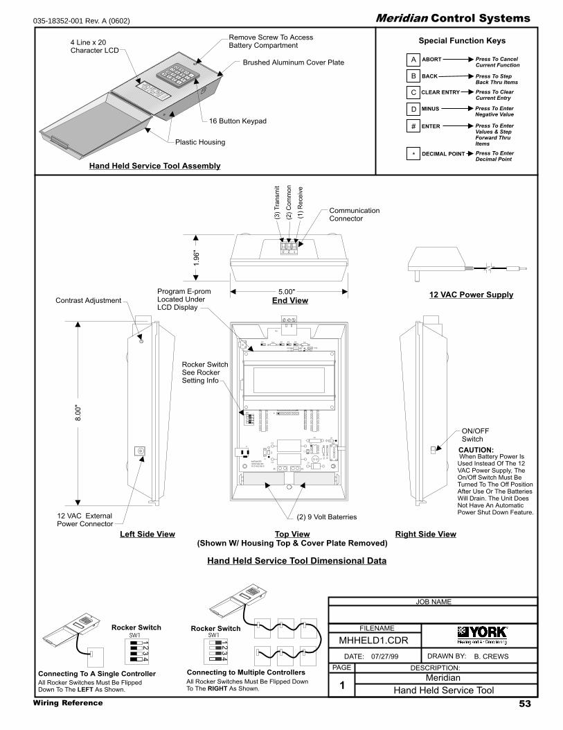
53Wiring Reference
Meridian Control Systems035-18352-001 Rev. A (0602)
1234
Rocker SwitchSee RockerSetting Info
(1)Receive
(2)Common
(3)Transmit
8.00"
5.00"
1.96"
12 VAC ExternalPower Connector
Contrast Adjustment
Program E-promLocated UnderLCD Display
(2) 9 Volt Baterries
2
85
0A
CB
D
1
74
*3
96
#
1)SE
TTI
ME&
DATE
2)RE
AD/R
ESET
UNIT
S
3)GL
OBAL
FORC
EMO
DE
4)AI
RBA
LANC
EMO
DE
P1
J1
R13
X1
BT2BT1
R9
SW2
V1
R7
D1
D3
JP4JP3JP2JP1
CX7
+
C6
+
C5
C4
C1
CX5
CX4
CX3CX2
CX1
SW1
P2
U7
U1
U2 U3
U4
U5
U6
RN1RN2
R1
R2
R3
R4
R5
R6
R8
R10
R11R12
L1
Q1
C3
C2
D2
TB1
WATTMASTER
HAND HELD BD.
YS101552 REV.0
3 2 1
FILENAME
DATE: B. CREWS
DESCRIPTION:PAGE
DRAWN BY:
Hand Held Service Tool1
JOB NAME
07/27/99
MHHELD1.CDR
ON/OFFSwitch
CommunicationConnector
12 VAC Power Supply
Left Side View Right Side ViewTop View(Shown W/ Housing Top & Cover Plate Removed)
End View
Hand Held Service Tool Assembly
Hand Held Service Tool Dimensional Data
Remove Screw To AccessBattery Compartment4 Line x 20
Character LCD
16 Button Keypad
Brushed Aluminum Cover Plate
Plastic Housing
When Battery Power IsUsed Instead Of The 12VAC Power Supply, TheOn/Off Switch Must BeTurned To The Off PositionAfter Use Or The BatteriesWill Drain. The Unit DoesNot Have An AutomaticPower Shut Down Feature.
All Rocker Switches Must Be Flipped DownTo The As Shown.RIGHT
All Rocker Switches Must Be FlippedDown To The As Shown.LEFT
A
B
C
D
#
*
ABORT
BACK
CLEAR ENTRY
MINUS
ENTER
DECIMAL POINT
Special Function Keys
Press To ClearCurrent Entry
Press To StepBack Thru Items
Press To EnterNegative Value
Press To EnterValues & StepForward ThruItems
Press To CancelCurrent Function
Press To EnterDecimal Point
11
22
33
44
SW1SW1
2
85
0A
CB
D
1
74
*3
96
#
2
85
0A
CB
D
1
74
*3
96
#
Connecting to Multiple ControllersConnecting To A Single Controller
CAUTION:
Rocker SwitchRocker Switch
Meridian

Wiring Reference54
Meridian Control Systems 035-18352-001 Rev. A (0602)
Notes:
2.)All Wiring To Be In Accordance With Local AndNational Electrical Codes and Specifications.
1.)The Wiring Diagrams Shown Are For Typical AirTo Air Heat Pump Units. Some Systems MayControl The Reversing Valve Internally WithinThe Air To Air Heat Pump Unit Circuitry. TheseUnits Can Be Wired Per The Standard CVWiring Diagrams. If Your Air To Air Heat PumpDiffers From The Diagrams Depicted PleaseConsult York Technical Support For WiringInformation.
FILENAME
DATE: B. THRALL
DESCRIPTION:PAGE
DRAWN BY:
Typical Air To Air Heat Pump Wiring1
JOB NAME
05/14/02
MCVA2AHPALL.CDR
Meridian CV Controller
Air to Air HeatPump Unit
Air to Air HeatPump Unit
Air to Air HeatPump Unit
Air to Air HeatPump Unit
R1
R1R1
R1
Connect to Ground Sideof Air To Air Heat PumpUnit Transformer
Connect to Ground Sideof Air To Air Heat PumpUnit Transformer
Connect to Ground Sideof Air To Air Heat PumpUnit Transformer
Connect to Ground Sideof Air To Air Heat PumpUnit Transformer
O (Reversing Valve
O (Reversing ValveO (Reversing Valve
O (Reversing Valve
R1-1
R1-1
R1-1
R1-1
R
RR
R
G ( Fan)
G ( Fan)G ( Fan)
G ( Fan)
Y1 (Compressor)
Y1 (Compressor)Y1 (Compressor)
Y2 (Compressor)Y2 (Compressor)
Y1 (Compressor)
W2 (Aux Heat)
W1 (Compressor 1 & 2)W1 (Compressor 1 & 2)
W2 (Aux Heat)W2 (Aux Heat)
W2 (Aux Heat)
W1 W1
Single Compressor UnitReversing Valve Fails To Cool Position
Single Compressor UnitReversing Valve Fails To Heat Position
Dual Compressor UnitReversing Valve Fails To Cool Position
Dual Compressor UnitReversing Valve Fails To Heat Position
CV ControllerWiring Terminals
CV ControllerWiring Terminals
CV ControllerWiring Terminals
CV ControllerWiring Terminals
RELAYOUTPUTS
RELAYOUTPUTS
RELAYOUTPUTS
RELAYOUTPUTS
COM4-5
COM4-5
COM4-5
COM4-5
OUT1
OUT1
OUT1
OUT1
OUT2
OUT2
OUT2
OUT2
OUT3
OUT3
OUT3
OUT3
OUT4
OUT4
OUT4
OUT4
OUT5
OUT5
OUT5
OUT5
COM1-3
COM1-3
COM1-3
COM1-3
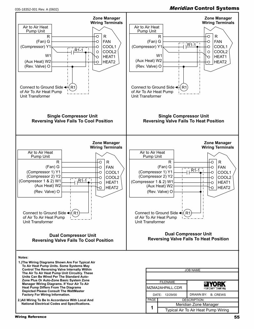
55Wiring Reference
Meridian Control Systems035-18352-001 Rev. A (0602)
Notes:
2.)All Wiring To Be In Accordance With Local AndNational Electrical Codes and Specifications.
1.)The Wiring Diagrams Shown Are For Typical AirTo Air Heat Pump Units. Some Systems MayControl The Reversing Valve Internally WithinThe Air To Air Heat Pump Unit Circuitry. TheseUnits Can Be Wired Per The Standard Auto-Zone Plus Or Auto-Zone Basic System ZoneManager Wiring Diagrams. If Your Air To AirHeat Pump Differs From The DiagramsDepicted Please Consult The WattMasterFactory For Wiring Information.
Air to Air HeatPump Unit
Air to Air HeatPump Unit
Air to Air HeatPump Unit
Air to Air HeatPump Unit
HEAT2
HEAT2 HEAT2
HEAT2
HEAT1
HEAT1 HEAT1
HEAT1
COOL2
COOL2 COOL2
COOL2
COOL1
COOL1 COOL1
COOL1
FAN
FAN FAN
FAN
R
R R
R
FILENAME
DATE: B. CREWS
DESCRIPTION:PAGE
DRAWN BY:
Typical Air To Air Heat Pump Wiring1
JOB NAME
12/29/00
MZMA2AHPALL.CDR
Meridian Zone Manager
R1
R1 R1
R1Connect to Ground Sideof Air To Air Heat PumpUnit Transformer
Connect to Ground Sideof Air To Air Heat PumpUnit Transformer
Connect to Ground Sideof Air To Air Heat PumpUnit Transformer
Connect to Ground Sideof Air To Air Heat PumpUnit Transformer
(Rev. Valve) O
(Rev. Valve) O (Rev. Valve) O
(Rev. Valve) O
R1-1
R1-1
R1-1
R1-1
R
R R
R
(Fan) G
(Fan) G (Fan) G
(Fan) G
(Compressor) Y1
(Compressor 1) Y1 (Compressor 1) Y1(Compressor 2) Y2 (Compressor 2) Y2
(Compressor) Y1
W1
(Compressor 1 & 2) W1 (Compressor 1 & 2) W1
W1
(Aux Heat) W2
(Aux Heat) W2 (Aux Heat) W2
(Aux Heat) W2
Single Compressor UnitReversing Valve Fails To Cool Position
Single Compressor UnitReversing Valve Fails To Heat Position
Dual Compressor UnitReversing Valve Fails To Cool Position
Dual Compressor UnitReversing Valve Fails To Heat Position
Zone ManagerWiring Terminals
Zone ManagerWiring Terminals
Zone ManagerWiring Terminals
Zone ManagerWiring Terminals

Wiring Reference56
Meridian Control Systems 035-18352-001 Rev. A (0602)
WM PN: OE340Y-10-STG
MZMSTGEXP1.CDR
FILENAME
JOB NAME
DESCRIPTION:
Staging Expansion Board Wiring
2ZEB004701024
DATE DRAWN:
PAGE
1
05/18/01 B. CREWSDRAWN BY:
Transformer VA Sizing RequirementsZone Manager = 25VA
Staging Expansion Board = 20VA
LINE 24VAC
GND
WARNING!OBSERVE CORRECT POLARITY
THROUGHOUT SYSTEM!
Zone Manager 21ZMP004700124
3-wayConnectorCable
2ZEB004701024Staging Expansion Board
GND
24VAC
OFF
All switches (1 thru 4)must be in the“ON” position
Minilink Board
R - (24VAC)
+
+
++
+
++
+ +
HEAT2
HEAT1
COOL2
COOL1
FAN
R
2
8C
SW1
16AB 24
ADD
LOCALLOOPT
SH
RTB3
COMM
T
SH
R
32
16
8
4
1
2
MINILINK
R9
R10
R8
I CEXPPORT
PWR
V4
V3
CLOSE
OPEN
FDBK
REC
GND
GND
24VAC
AUX1
OPEN
K1
NETWORKLOOP
SH
R
T
CLOSE
K2
NE5090
ANALOGOUTPUTS
A2
G
TB2
A1
N.O.
EXHAUSTCONTACTS
GND
GND
AUX3
AUX2
7824
D25
U14
VR3
R40
ADJUST5.11V
C27
7812 C26
VR2
D1
D3
D4
D2
PJ1
PRESSURE
SENSORJACK
+5V
R7
OAT
RAT
+12V
SAT
ANALOGINPUTS
GND
SIG
Heat
Heat
Heat
Heat
Cool
Cool
Cool
Cool
G - (Fan)
Y1 - (Cool1)
W1 - (Heat1)
Y3 - (Cool3)
W3 - (Heat3)
W5 - (Heat5)
Y2 - (Cool2)
W2 - (Heat2)
Y4 - (Cool4)
Y5 - (Cool5)
Y6 - (Cool6)
W4 - (Heat4)
W6 - (Heat6)
HVACUnitTerminals
Minilink Board
Zone Manager Board
Staging Expansion Board
Cable Connection Detail
.
Use 3-Way Cable When ConnectingStaging Expansion Board To MinilinkAnd Zone Manager Boards
All Contacts Are N.O.- All Contacts Are Rated For24VAC Pilot Duty Only. Do Not Apply Any VoltageHigher Than 24VAC

57Wiring Reference
Meridian Control Systems035-18352-001 Rev. A (0602)
AOUT
AOUT
GNDGND
GND
AIN5
AIN1AIN2AIN3AIN4
12V
GND
24VAC
PWR
NETTOKEN32168421
TR
T1
P
P1
24VAC24VAC
Zone Manager
CV or CV-C Controller
Wiring 2ZAI004700266 Actuator Interface Module Kit To CV & CV-C Controllers (CV, CV-EX & Plus Systems)
Wiring 2ZAI004700266 Actuator Interface Module Kit To Zone Manager (Basic & Plus Systems)
Installing 2ZAM0047000024 Interface Module To Honeywell M7415 Or 7405 Actuator
Q769C1007 Interface Module(2ZAM0047000024)
Q769C1007 Interface Module(2ZAM0047000024)
Warning:
!
An Isolation TransformerMust Be Used For Connection ToActuator Or Serious Damage WillResult
Warning:
!
An Isolation TransformerMust Be Used For Connection ToActuator Or Serious Damage WillResult
+
TR1
T
-
A1
G
TB2
A2
G
OUTPUTSANALOG
A1
N.O.CONTACTSEXHAUST
AUX3
GND
GND
AUX2
AUX1
ANALOG
SAT
OAT
RAT
INPUTS+12V
Honeywell Series M7415Or M7405 Actuator
Honeywell Series M7415Or M7405 Actuator
Notes:
1.)All Wiring To Be In AccordanceWith Local And National ElectricalCodes And Specifications.
24VAC
24VAC
T1 T1
TR TR
T T
P
P1
TR1
TR1
SENSOR
SENSOR
MINPOSN
M7415A1014
025-26250
M7415A1014
025-26250
TR
T1
P
P1
24VAC24VAC
24 VAC - Isolation Transformer
24 VAC - Isolation Transformer
(?????????????)
(?????????????)
+
TR1
T
-
Honeywell M7415 ActuatorWithout Interface Module
Honeywell M7415 Actuator WithQ769C1007 2ZAM0047000024)Interface Module Installed
Place Interface Module OnTerminals P1 and P
WM PN: OE266Y-01
FILENAME
DATE: B. CREWS
DESCRIPTION:PAGE
DRAWN BY:
Actuator Interface Module Wiring
JOB NAME
07/12/99
MHWACTIFB.CDR
2ZAI0047002661

Wiring Reference58
Meridian Control Systems 035-18352-001 Rev. A (0602)
FILENAME
DATE: B. CREWS
DESCRIPTION:PAGE
DRAWN BY:
Chip Replacement - General Instructions
Socketed I.C.
JOB NAME
07/14/99
MGENCHPR.CDR
1
Small FlatheadScrewdriver
Chip
Chip
Printed CircuitBoard
Printed CircuitBoard
Printed CircuitBoard
Chip
WARNING!
Direction Of Pull
Notch
Dot
Pin1
Be sure the chip you have selected to replace is asocketed chip. Not all driver chips on the boardsare field replaceable. Only socketed chips may beremoved and replaced in the field. All other chipsthat are not socketed will require sending the boardto the YORK factory for repair.
Once you have determined that thechip needing replacement is indeed a socketed chipplease proceed in the following manner.
Remove the communications loop connector andthen the 24VAC power connector on the controllerbefore attempting to change any components.
will occur if components are removed orinstalled with power applied.
If you are unsure how to safely remove the chip orabout the correct pin placement, please consult thefactory before proceeding.
Use extreme care to avoid inserting the screwdriveror I.C. Puller under the socket. You must insert the tipof the screwdriver or ends of the I.C. Puller betweenthe body of the chip and the chip socket.
Each chip be installed with Pin 1 in the correctlocation. Installing the chip “backwards” will in mostcases destroy the device when power is reapplied.
Pin 1 can be located by looking for the notch in the endof the chip. Pin 1 on "some" chips is identified with a dot.
Be certain that pins are lined up in the socketbefore pressing the chip in. Failure to properly lineup the pins will result in damage to the chip.This is a common error -
Only after confirming that the chip has been correctlyinstalled with Pin 1 in the proper position and that thepins are lined up and none are bent or out of the socket,should communication or power wiring be reconnectedto the board. Tp prevent possible damage alwaysreconnect the power wiring first and then thecommunication wiring.
If you try toremove a chip that is not socketed it will destroythe circuit board.
DAMAGE
Damage to the board caused by failure to correctlyremove or install the chip is not covered by theYORK warranty.
MUST
ALL
VERY BE CAREFUL.
Using I.C. Puller To Remove Socketed Chip
Using Screwdriver To Remove Socketed Chip
End View Of Socketed Chip AssemblyTop View Of Socketed Chip Assembly
I.C. Puller
Chip Socket
Chip Socket
Chip Socket
Gently Rock Chip Side To Side And ThenLift Straight Up To Remove Chip FromChip Socket.
Gently Lift The Chip On One End And Rock ChipBack And Forth With Screwdriver As Shown.Repeat This Process On The Other End Of Chip.Alternate This Process On Both Ends Of Chip UntilThe Chip Is Free From The Chip Socket.
Pin 1
Dot
Socket
PrintedCircuitBoard
Typical RS-485 CommunicationsDriver Chip Detail

59Wiring Reference
Meridian Control Systems035-18352-001 Rev. A (0602)
Pin 1
Dot
Socket
PrintedCircuitBoard
Typical RS-485 CommunicationsDriver Chip Detail
Comm Driver Chip( U10 )
Pin 112345678
OFFOFF
124816
ADDRESS
T'STAT
COMM
POWER
Zone ControllerLighting Panel Controller AndOptimal Start Scheduler
System Manager
Comm Driver Chip( U1 )Pin 1
Commlink II
Comm Driver Chip(U2)
Pin 1
CV Controller,CV-C ControllerGPC Contoller, Wetbulb Controller
COMM
T
SHLD
LD4
REC.
RAM485COMM
R
Pin 1
Pin 1
Comm Driver Chip( U5 )
Comm Driver Chip( U3 )
Warning!Use Extreme Caution When Removing Any ChipsTo Avoid Damaging Any Circuit Board Traces WhichAre Under The Chip.
Be Sure That Any Small Screwdriver Or OtherSharp Object Used To Remove The Chip Does NotCome Into Contact With The Printed Circuit BoardSurface.
A Small Screwdriver May Be Inserted Between TheChip And The Socket To Aid In Removal Of The Chip.
Be Very Careful Not To Insert The Screwdriver UnderThe Socket!! Damage To The Board Is Not CoveredBy Warranty.
Zone Manager
Network LoopComm Driver Chip
( U5 )
Local LoopComm Driver Chip
( U8 )
Zone ManagerComm Driver Chip
( U15 )
Pin 1
Pin 1
Pin 1
EPROM
RAM
PAL
T
SH
R
WM PN: ID075176-10
MDRCHPREP.CDR
FILENAME
JOB NAME
DESCRIPTION:
RS-485 Driver Chip Replacement
2ZDC004700124
DATE DRAWN:
PAGE
1
06/06/01 B. CREWSDRAWN BY:

Wiring Reference60
Meridian Control Systems 035-18352-001 Rev. A (0602)
Notes:

61Wiring Reference
Meridian Control Systems035-18352-001 Rev. A (0602)
AAAAAppendixppendixppendixppendixppendix

Wiring Reference62
Meridian Control Systems 035-18352-001 Rev. A (0602)
Zone Manager
Feedback (BK)
Close (GR)
Open (YL)
Gnd (WH)
Notes:
1.)24 VAC Must Be Connected SoThat All Ground Wires RemainCommon.
3.)All Communication Wiring To Be 18Ga. Minimum, 2 Conductor TwistedPair With Shield. Belden #82760 OrEquivalent.
4.)For Individual Component Wiring SeeSpecific Component Wiring Diagram.
5.)It Is Recommended That AllControllers Address Switches AreSet Before Installation.
2.)All Wiring To Be In Accordance WithLocal And National Electrical Codesand Specifications.
RS-485Communications To Zone
Controllers
Return Air Temp.Sensor
Supply Air Temp.Sensor
LineVoltage
HVACUnit
24VAC Only
Red
Blk
To Relief / Exhaust Fans
Grn
StaticPick-up
StaticPressureSensor
Splice AsRequired
LO HI
GND
24VAC
Belimo Actuator Wiring Shown.Consult Factory For Other
Models Of Economizer Actuators.Some Actuators Require IsolationTransformers In Order To PreventDamage To The Controller Board.
WARNING!
Use Extreme Care When WiringEconomizer Actuators
Never Connect Or DisconnectWiring With Power Applied!
Never Apply Power If TheGnd ( 1 Com ) Terminal On TheActuator Is Not Connected.
See Note 1 &2
Outdoor Air Temp.Sensor
(See Note 4)
Aux3ForcedOccupiedMode
Aux1EconomizerDisable
Aux2FilterAlarm
Auxiliary Inputs( Dry Contacts )
R
G
Y1
Y2
W1
W2
Economizer Actuator
133 IN-LB
AF24-SR
1 COM
2 +
3 Y1
4 Y2
5 UBELIMO
For Detailed ConnectionsAnd Slave WiringSee Bypass ActuatorWiring Drawing Filename:MBAWR3.CDR
Actuator WiringInterface
Bypass Air DamperActuator
10
FILENAME
DATE: B. CREWS
DESCRIPTION:PAGE
DRAWN BY:
Zone Manager Wiring2
JOB NAME
12/15/99
MBAWR2OLD.CDR
Meridian Basic
C987
CABLE
R6
R5
HEAT 2 SW1
W2
W1
Y2
HEAT2
HEAT1
COOL2
COOL1
FAN
HEAT 1
COOL 2
COOL 1
C 1992
1
1632
BNET
248
ADD
COMM DRIVER
RS-485
75176
MADE IN U.S.A.
D17
D18
D19
D20
D21
D22
D23
D24
0* # D
R
SH
T
COMM
C1C2
+
P1
RIBBON
GND
G
Y1V6
V5
CLOSE
V4
V3
OPEN
GND
FDBK
FAN
CLOSE
OPEN
+
REC
+
GND
NE5090
4 5 6
KEYPAD
1 2 3
B
A
LCD DISPLAY
&
++
24VAC
TB2
POWER
+
++
ADJUST
5.11V
PJ1
++PRESSURE
SENSORJACK
+5V
SIG
BUSS
EXP
TB2
A2
G
OUTPUTS
ANALOG
A1
N.O.
CONTACTS
EXHAUST
AUX3
GND
GND
AUX2
AUX1
ANALOG
SAT
OAT
RAT
INPUTS
+12V
TB12
BYPASS
BYPASS
Local Loop
Address Switch Must Always Be SetTo Address 0 on Zone Manager Board
As Shown
Zone ManagerAddress Switch
These Switches Must BeIn The OFF PositionAs Shown
ADD
12
481632B
NET
ADD
32BNET
16 8 4 12
OFF
>
OFF
>
RockerDown
RockerDown

63Wiring Reference
Meridian Control Systems035-18352-001 Rev. A (0602)
Zone Manager
Notes:
1.)24 VAC Must Be Connected SoThat All Ground Wires RemainCommon.
3.)All Communication Wiring To Be 18Ga. Minimum, 2 Conductor TwistedPair With Shield. Belden #82760 OrEquivalent.
5.)For Individual Component Wiring SeeSpecific Component Wiring Diagram.
6.)It Is Recommended That AllControllers Address Switches AreSet Before Installation.
2.)All Wiring To Be In Accordance WithLocal And National Electrical Codesand Specifications.
RS-485Communications To ZoneControllers, CV ControllersAnd/Or System Manager
Return Air Temp.Sensor
Supply Air Temp.Sensor
LineVoltage
HVACUnit
24VAC Only
Red
Blk
To Relief / Exhaust Fans
Grn
StaticPick-up
StaticPressureSensor
Splice AsRequired
LO HI
GND
24VAC
Belimo Actuator Wiring ShownConsult Factory For Other
Models Of Economizer ActuatorsSome Actuators Require IsolationTransformers In Order To PreventDamage To The Controller Board.
WARNING!
Use Extreme Care When WiringEconomizer Actuators
Never Connect Or DisconnectWiring With Power Applied!
Never Apply Power If TheGnd ( 1 Com ) Terminal On TheActuator Is Not Connected.See Note 1 &2
+
+
++
+
++
+ +
HEAT2
HEAT1
COOL2
COOL1
FAN
R
2
8C
SW1
16AB 24
ADD
LOCALLOOP
Local Loop
T
SH
RTB3
COMM
T
SH
R
32
16
8
4
1
2
MINILINK
R9
R10
R8
I CEXPPORT
PWR
V4
V3
CLOSE
OPEN
FDBK
REC
GND
GND
24VAC
AUX1
OPEN
K1
NETWORKLOOP
Network Loop RS-485
To Other ZoneManagers and/orCommLink onSystem
SH
R
T
CLOSE
K2
NE5090
ANALOGOUTPUTS
A2
G
TB2
A1
N.O.
EXHAUSTCONTACTS
GND
GND
AUX3
AUX2
7824
D25
U14
VR3
R40
ADJUST5.11V
C27
7812 C26
VR2
D1
D3
D4
D2
PJ1
PRESSURE
SENSORJACK
+5V
R7
OAT
RAT
+12V
SAT
ANALOGINPUTS
GND
SIG
T
R
SHIELD
T
R
SHIELD
Outdoor Air Temp.Sensor
(See Note 4)
Aux3ForcedOccupiedMode
Aux1EconomizerDisable
Aux2FilterAlarm
Auxiliary Inputs( Dry Contacts )
R
G
Y1
Y2
W1
W2
Economizer Actuator
133 IN-LB
AF24-SR
1 COM
2 +
3 Y1
4 Y2
5 UBELIMO
For Detailed ConnectionsAnd Slave WiringSee Bypass Actuator WiringDrawing Filename:MPLWRNEW4.CDR
See Drawing Filename:MPLWRNEW5.CDR ForAddress Switch Settings
Bypass Air DamperActuator
10
4.)Only One Outside Air Sensor IsRequired Per System. It May BeConnected To Any CV Controller OrZone Manager On The System. If AWetbulb Module Controller Is Used TheOA Sensor Must Be Connected To TheWetbulb Module.
FILENAME
DATE: B. THRALL
DESCRIPTION:PAGE
DRAWN BY:
Zone Manager Wiring3
JOB NAME
02/05/01
MPLWRNEW3.CDR
Meridian Plus
FROMZONE
CONTROLLER
BYPASSAND
SLAVEINTERFACE
YS101824
TOACTUATOR
OPEN
CLOSE
OPEN
GND
PJ1
PJ2LD2
LD1
CLOSE
TB
1T
B2
Bypass Interface Card
OPEN
CLOSE
FDBK
GND

Wiring Reference64
Meridian Control Systems 035-18352-001 Rev. A (0602)
BYPASS ACTUATOR #3 (SLAVE)(WHEN USED)BYPASS ACTUATOR #2 (SLAVE)
BYPASS ACTUATOR #1(MASTER)
MODULAR PHONE CABLE
MODULARPHONECABLE
MODULARPHONECABLE
11 00
10
OPEN
OPEN
COMMON
COMMONCLOSE
OPENFEEDBACK
COMMON
CLOSE
CLOSE
ACTUATORWIRING
INTERFACE(SHOWN WITH
COVER REMOVED)
ACTUATORWIRING
INTERFACE(SHOWN WITH
COVER REMOVED)
ACTUATORWIRING
INTERFACE(SHOWN WITH
COVER REMOVED)
FEEDBACKFEEDBACK
USEUSE
DO NOTDO NOT
USEUSEDO NOTDO NOT GNDGND
CLOSECLOSE
OPENOPEN
RR
DDRR
KKBB
OO
LLBB
RR
GG
LL
YY
WHWH
RR
BB
LL
S
FEEDBACK
USE
DONOT
USE
DONOT
GND
CLOSE
OPEN
R DRKBOLB
RGLY
WH
RBLS
S
TO ZONEMANAGER
Note: Observe TerminalWire Color Coding NotPhysical Location AsTerminal PhysicalLocation May Vary.
Note: ObserveTerminal Wire ColorCoding Not PhysicalLocation As TerminalPhysical LocationMay Vary.
Note: ObserveTerminal Wire ColorCoding Not PhysicalLocation As TerminalPhysical LocationMay Vary.
FILENAME
DATE: B. CREWS
DESCRIPTION:PAGE
DRAWN BY:
Bypass -Slave Wiring1
JOB NAME
03/26/99
MBYSWR1.CDR
Meridian
If The Wiring Interface YouHave On Your System DoesNot Look The One ShownPlease See Page 64 ForCorrect Wiring Information.

65Wiring Reference
Meridian Control Systems035-18352-001 Rev. A (0602)
SLAVED-ZONE ACTUATOR #2(WHEN USED)SLAVED-ZONE ACTUATOR #1
ZONE CONTROLLER BOARD
ZONE ACTUATOR(MASTER)
MODULAR PHONE CABLES
MODULARPHONECABLE
MODULARPHONECABLE
11 00
SLAVE ACTUATORTERMINAL CARD(SEE NOTE 1)
10
CONTROLLER ACTUATOR
PJ1 PJ2
OPEN
OPEN
OPEN
SLAVES
COMMON
COMMON
COMMON
CLOSE
CLO
SE
ACTUATOR
CLO
SE
TB1
ACTUATORWIRING
INTERFACE(SHOWN WITH
COVER REMOVED)
ACTUATORWIRING
INTERFACE(SHOWN WITH
COVER REMOVED)
FEEDBACKFEEDBACK
USEUSE
DO NOTDO NOT
USEUSEDO NOTDO NOT GNDGND
CLOSECLOSE
OPENOPEN
RR
DDRR
KKBB
OO
LLBB
RR
GG
LL
YY
WHWH
RR
BB
LL
SS
Note:1.) A Slave Wiring Adapter consisting of a slave actuator terminalcard and modular phone cable is supplied with the RoundSlaved-Zone Damper, Rectangular Slaved-Zone Damper Kit andthe Slaved Zone Package. It is required when attaching slaveactuator(s) to the master zone damper. The slave actuatorterminal card should be mounted to the control enclosure of themaster zone damper. It is mounted by means of the adhesivetape on the back of the slave actuator terminal card. Connect oneof the modular phone cables to the slave actuator terminal cardand the other end to the master actuator.
SLAVE WIRINGADAPTER
Note: ObserveTerminal Wire ColorCoding Not PhysicalLocation As TerminalPhysical LocationMay Vary.
Note: ObserveTerminal Wire ColorCoding Not PhysicalLocation As TerminalPhysical LocationMay Vary.
FILENAME
DATE: B. CREWS
DESCRIPTION:PAGE
DRAWN BY:
Zoned-Slave Wiring1
JOB NAME
03/26/99
MSLVWR1.CDR
Meridian

Wiring Reference66
Meridian Control Systems 035-18352-001 Rev. A (0602)
Notes:

67Wiring Reference
Meridian Control Systems035-18352-001 Rev. A (0602)
Notes:

Subject to change without notice. Printed in U.S.A.
Copyright by Unitary Products Group 2002. All rights reserved.
UnitaryProductsGroup
5005YorkDrive
NormanOK
73069
035-18352-001 Rev. A (0602)
Supersedes: Nothing