control systems - acuity · pdf filepsg9 lithonia control systems 654 controllable breaker...
TRANSCRIPT

PSG9652
LITH
ON
IA C
LITH
ON
IA C
LITH
ON
IA C
LITH
ON
IA C
LITH
ON
IA C
ON
TRO
L SY
ON
TRO
L SY
ON
TRO
L SY
ON
TRO
L SY
ON
TRO
L SY
STEM
SST
EMS
STEM
SST
EMS
STEM
S
www.lithonia.com
CConontrtrol Sol Syyststemsems
Lithonia Lighting produces a wide range of control
systems for both architectural dimming and lighting
energy management. These systems are suitable for
applications in high-rise office buildings, educational
facilities, multi-building complexes, manufacturing
plants and sports facilities.
Lighting controls dramatically enhance efficiency by
governing the amount of light needed to maintain
illuminance levels and by limiting light use to occupied
spaces. Lithonia offers a variety of lighting control
solutions to meet ASHRAE 90.1 and similar legislation
requirements.

PSG9 653
LITHO
NIA
CLITH
ON
IA C
LITHO
NIA
CLITH
ON
IA C
LITHO
NIA
CON
TROL SY
ON
TROL SY
ON
TROL SY
ON
TROL SY
ON
TROL SYSTEM
SSTEM
SSTEM
SSTEM
SSTEM
S
www.lithonia.com
CONTENTSCONTENTSCONTENTSCONTENTSCONTENTS
SynergySynergySynergySynergySynergy® Lighting Lighting Lighting Lighting Lighting Control SystemsControl SystemsControl SystemsControl SystemsControl Systems
System Overview 654PC Software 656Digital Wallstations 657Digital Equinox® 659Dry Contact Switches 662SweepSwitch® 662Relay and Dimming Panels 663Controllable Breaker Panels 669System Accessories 670
SwitchPakSwitchPakSwitchPakSwitchPakSwitchPak® 671
LitronicLitronicLitronicLitronicLitronic® Occupancy Sensors Occupancy Sensors Occupancy Sensors Occupancy Sensors Occupancy Sensors 672
Wallbox DimmersWallbox DimmersWallbox DimmersWallbox DimmersWallbox Dimmers
Sequel IDC 675DSD 677ISD 678
Remote DimmersRemote DimmersRemote DimmersRemote DimmersRemote Dimmers 676
Fluorescent Dimming GuideFluorescent Dimming GuideFluorescent Dimming GuideFluorescent Dimming GuideFluorescent Dimming Guide 680
657 657
659 663
669 671
677
Good Better BestSwitchPak w/ SR option page 671 Synergy MLX pages 654-670
(on/off control only) (on/off and dimming control)Occupancy Sensors pages 672-674 SwitchPak page 671
SweepSwitch page 662 Digital Equinox page 660
SweepSwitch page 662 Digital Equinox pages 659-660 pages 654-670, pages 659-660Synergy MLX with Digital Equinoxpages 654-670, pages 659-660
SolutionApplication
Building-wide Control
Energy Management - on/off only Synergy MLC or MLX pages 654-670
Classroom Control
University / College Campus
ISD DPC page 679
SwitchPak page 671
Sequel IDC page 675
Timeclock control
Architectural Dimming
Energy Management - dimming(Daylight Harvesting)
Wallbox Dimming
Occupancy Sensors pages 672-674 SwitchPak w/ SR option page 671
Synergy MLC pages 657-670 Synergy MLX pages 654-670
Synergy MLX pages 654-670Synergy MLC pages 657-670
Digital Equinox page 659 Synergy MLX pages 654-670
DSD page 677 ISD pages 678-679 Sequel IDC page 675
Occupancy Sensors pages 672-674 SwitchPak page 671 Synergy MLX with Digital Equinox
672

PSG9
LITH
ON
IA C
ON
TRO
L SY
STEM
SLI
THO
NIA
CO
NTR
OL
SYST
EMS
LITH
ON
IA C
ON
TRO
L SY
STEM
SLI
THO
NIA
CO
NTR
OL
SYST
EMS
LITH
ON
IA C
ON
TRO
L SY
STEM
S
654
Controllable BreakerProvides individual controlof each circuit breaker and works with all standard Synergy® controller and userinterface options. (page 669)
Digital Equinox StationProvides distributedfluorescent control. Maybe used stand-alone or aspart of a fully integratedSynergy® system. (page 659-661)
RemoteRelay(page 674)
Photocell(page 661)
Occupancy Sensor (page 672-673)
Photocell(page 670)
OverrideSwitch (page 662)
Digital Remote Station1 to 9 buttons in a singlegang. Optionalwirelessreceiverforoperationand programming of presetsfrom hand-held transmitter.(page 658)
Preset ControlStation4, 8, 12 and16 channel masterstation with 6 to16 preset lightingscenes. (page 657)
Local Area NetworkEach system controllersupports up to 60 digitalstations.
RS232 InterfaceLocal A/V system andlaptop connection forprogramming andoperation. (page 665)
Telephone Interface(Optional) voice modemprovides remote PC access and override of lighting via any touchtone telephone.(page 665)
DMX Theatrical Control(Optional) DMX interface allowsSynergy® relays and dimmers to becontrolled by theatrical systems.(page 665)
System ControllerPlug-in unit provides for panelprogramming and operation,network communication, andastronomic timeclock. (page 665)
Synergy ® L igh t ing Cont ro l Sy s tem Overv iew
Fixture with step dimmingoption or with four-wiredimming ballast
www.lithonia.com, keyword: Synergy
SYN
ERG
Y® C
ON
TRO
L SY
STEM
SYN
ERG
Y® C
ON
TRO
L SY
STEM
SYN
ERG
Y® C
ON
TRO
L SY
STEM
SYN
ERG
Y® C
ON
TRO
L SY
STEM
SYN
ERG
Y® C
ON
TRO
L SY
STEM

PSG9
LITHO
NIA
CON
TROL SYSTEM
SLITH
ON
IA CO
NTRO
L SYSTEMS
LITHO
NIA
CON
TROL SYSTEM
SLITH
ON
IA CO
NTRO
L SYSTEMS
LITHO
NIA
CON
TROL SYSTEM
S
655
Occupancy Sensor(page 672-673)
Relay ModuleEight single-pole relays with zero-cross switching, plus eight switchand two analog input terminals.(page 666)
DALI Control ModuleNetwork controllers and power supplies for three DALI networks.(page 667)
Relays with BreakersAs above with either six120V, four 277V or four347V branch circuit breakers.(page 666)
Dimmer ModuleSix universal load digitaldimmers suitable for 120Vor 277V incandescent,fluorescent, low voltage,neon, cold cathode andnon-dim loads.(page 666)
Ballast Control ModuleEight channels of 0-10VDCdimming with integrated 20Arelays for four-wire dimmingballasts. Available with 120V,277V and 347V circuit breakers.(page 667)
Tap Feed Lug OptionAllows several Synergyenclosures to share a singlemain feed up to 400 ampsthree phase. (page 668)
BACnet WANAllows over 4 million Synergy® panels tointeract as an integrated system usingBACnet, the ANSI and ISO standard forbuilding automation.
Interactive GraphicsMonitor and control entire lighting system via virtualcontrol panel screens created with simple on-board tools, or import graphic image backgrounds andfloorplans to suit project requirements. (page 656)
Synergy® CONFIG SoftwareConfigure, control and monitorSynergy® lighting control panelson-site or remotely via phonelines or WAN with this easy-to-use Windows® application.(page 656)
System Enclosurefor Relays and DimmersThree capacities, up to48 relays or 30 dimmers each.(page 664)
Power Modu le Opt ionsMay be combined within the same enclosure to meet job site requirements
www.lithonia.com, keyword: Synergy
SYNERG
Y® CON
TROL SYSTEM
SYNERG
Y® CON
TROL SYSTEM
SYNERG
Y® CON
TROL SYSTEM
SYNERG
Y® CON
TROL SYSTEM
SYNERG
Y® CON
TROL SYSTEM

PSG9
LITH
ON
IA C
ON
TRO
L SY
STEM
SLI
THO
NIA
CO
NTR
OL
SYST
EMS
LITH
ON
IA C
ON
TRO
L SY
STEM
SLI
THO
NIA
CO
NTR
OL
SYST
EMS
LITH
ON
IA C
ON
TRO
L SY
STEM
S
656
Ordering Information Example: SYSW CONFIGSYSW CONFIGSYSW CONFIGSYSW CONFIGSYSW CONFIG
www.lithonia.com, keywords: SYSW CONFIG & SYSW GRAPHIC
System Configuration Software
SYSW CONFIG
Graphical Interface Software
SYSW GRAPHIC Intended Use
Adds real-time control and monitoring capabili-ties to a Synergy® system through the use of aflexible graphical interface. Runs as a fully inte-grated component of the SYSW CONFIG software(above) installed on a desktop, laptop or panel PCconnected to the system via an RS-485, Ethernetor wireless network connection.
Features
Provides intuitive and interactive point-and-click control of loads with status feedback and re-mote diagnostic capability. Simple setup andconfiguration options allow the creation of floor-plan-based, button-based or combination
Ordering Information Example: SYSW GRAPHICSYSW GRAPHICSYSW GRAPHICSYSW GRAPHICSYSW GRAPHIC
Accessories (Order separately)
SYSW SCREEN Factory-prepared SYSW GRAPHIC screen per userspecifications. Indicate quantity of screensrequired.
LSA PC PC workstation suitable for system configurationor graphics. Contact factory for mounting andtouchscreen options.
Intended Use
PC-based Windows™ application used to config-ure a Synergy® system equipped with MLX con-trollers (page 665). Allows on-site or remote pro-gramming and configuration of all system pa-rameters and schedules.
Features
Utilizes a familiar Windows™ graphical user inter-face to provide easy access to all system data. Asimple tab-based navigation scheme allows theuser to reach most configuration screens with asingle click of the mouse. Access privileges fordifferent software features can be set up for mul-tiple users through the use of administrator-de-fined login IDs and passwords.
Online mode allows real-time monitoring and
override of input and load status as well as diag-nostic functions.
Connection to the system may be made with thesupplied RS-232 cable through the front-mount-ed DB-9 connector on any system controller, ordirectly over the BACnet™ network (optionalnetwork interface card may need to be installedon PC). A connection may also be made from aremote site using standard telephone lines viathe PHONE option on the controller (see page665) and a PC equipped with a telephone mo-dem.
Minimum hardware requirements are a 266MHzPentium™ II class PC running Windows™ 2000 orlater operating system with 128 MB RAM, 30 MBfree disk space and 800 x 600 video resolution.
SYN
ERG
Y® C
ON
TRO
L SY
STEM
SYN
ERG
Y® C
ON
TRO
L SY
STEM
SYN
ERG
Y® C
ON
TRO
L SY
STEM
SYN
ERG
Y® C
ON
TRO
L SY
STEM
SYN
ERG
Y® C
ON
TRO
L SY
STEM
Series
SYSW CONFIG Synergy® configuration software
screens. Flexible control options allow graphicalobjects to directly monitor and override all sys-tem inputs (switches, photocells, digital sta-tions), outputs (relays, dimmers, controllablebreakers, DALI devices) room partitions and loadgroups. Integrated scheduling module allowsthe creation of temporary, PC-based schedulesfor special events.
Over 32,000 screens may be configured and thenumber of control objects per screen is limitedonly by screen resolution. Control screens maybe user-configured in the field or ordered facto-ry-prepared to client specifications via the SYSWSCREEN accessory.
Series
SYSW GRAPHIC Synergy® graphical user interface

PSG9
LITHO
NIA
CON
TROL SYSTEM
SLITH
ON
IA CO
NTRO
L SYSTEMS
LITHO
NIA
CON
TROL SYSTEM
SLITH
ON
IA CO
NTRO
L SYSTEMS
LITHO
NIA
CON
TROL SYSTEM
S
657
Intended Use
Provide manual dimming and preset lighting con-trol for architectural dimming applications. Of-fered in a variety of styles and architectural finish-es suitable for virtually any application. May bedaisy-chained together with SYRS digital remotestations (page 658) for multi-location control.
Features
Functions – Master raise and lower buttons adjustthe intensity of all lights dimmed from the station.Channel raise and lower buttons adjust the inten-sity level of individual channels. LED bar graph dis-plays intensity level. Select button saves presetsand fade time is adjustable for each preset scene.Preset button saves and activates presets. Off func-tion turns off all channels.
Architectural Preset Control Station
SQCS
Series
SQCS Sequel® controlstation
Number of presets and channels
6P 4C 6 presets, 4 channels6P 8C 6 presets, 8 channels
6P 12C 6 presets, 12 channels6P 16C 6 presets, 16 channels
Finish
BJ4 Brushed stainless steel,black buttons
WC2 Painted white, whitebuttons
IE3 Painted ivory, ivorybuttons
BL4 Painted black, blackbuttons1
BF4 Polished brass, blackbuttons1
Ordering Information Example: SQCS 6P 4C BJ4 TRSQCS 6P 4C BJ4 TRSQCS 6P 4C BJ4 TRSQCS 6P 4C BJ4 TRSQCS 6P 4C BJ4 TR
Accessories (Order separately)
SQCS 5GB 5 gang backbox for 4-channel and 8-channel stationsSQCS 8GB 8 gang backbox for 12-channel and 16-channel stations
BKLE Engraved button cap (specify button color and wording)
Series Width Thickness Height WeightSQCS 4C 10-1/8 (257) 1/4 (6) 4-5/8 (117) 2-1/2 (1.13)SQCS 8C 10-1/8 (257) 1/4 (6) 4-5/8 (117) 2-1/2 (1.13)SQCS 12C 15-7/16 (392) 1/4 (6) 4-5/8 (117) 4 (1.8)SQCS 16C 15-7/16 (392) 1/4 (6) 4-5/8 (117) 4 (1.8)
Dimensions are shown in inches (millimeters) or pounds (kilograms) unlessotherwise noted.
Intended Use
Used in conjunction with a Synergy® systemequipped with SYSC MLX controllers (page 665)to provide system-wide configuration, monitor-ing and override of lighting zones
Features
8.0" full-color TFT touchscreen graphical inter-face may be configured with floorplan-based orbutton-based screens. Flexible control optionsallow graphical objects to monitor and overrideany system input, output or load group as need-ed to satisfy project requirements. Screens maybe field or factory configured.
Graphical LCD User Interface
SYA LCD
www.lithonia.com, keywords: SQCS and SYA LCD
SYNERG
Y® CON
TROL SYSTEM
SYNERG
Y® CON
TROL SYSTEM
SYNERG
Y® CON
TROL SYSTEM
SYNERG
Y® CON
TROL SYSTEM
SYNERG
Y® CON
TROL SYSTEM
Integral dry contact closure interface allows ac-cess to 16 presets and master raise/lower and offfunctions for A/V systems and auxiliary equipment.
Installation: 4- and 8-channel stations mount inLithonia #SQCS 5GB or RACO 699 five-gang back-box; 12- and 16- channel stations mount in Litho-nia #SQCS 8GB backbox. Stations connect to a Syn-ergy® system controller (page 665) via the fourwire A4 control station network wire (page 670)which can be shared by up to 60 SQCS and SYRS(page 658) wallstations per system controller.
Classification – Class 2 low voltage device.
Ordering Information Example: SYA LCD SYA LCD SYA LCD SYA LCD SYA LCD
Series
SYA LCD 8.0" full color touch screen user interface (Maybe wall or panel mounted)1
Wallplate style
SD SolidTR Translucent
NOTES:
1 Additional delivery time and/or cost may be associated.
NOTES:1 Other screen sizes and mounting options are available. Consult factory for
information.
Listings
UL Listed to US and Canadian safety standards.
PSG9
LITH
ON
IA C
ON
TRO
L SY
STEM
SLI
THO
NIA
CO
NTR
OL
SYST
EMS
LITH
ON
IA C
ON
TRO
L SY
STEM
SLI
THO
NIA
CO
NTR
OL
SYST
EMS
LITH
ON
IA C
ON
TRO
L SY
STEM
S
658
Series
SYWR
Type
6B 6-button remote transmitterHHP 12-button hand-held
programmer
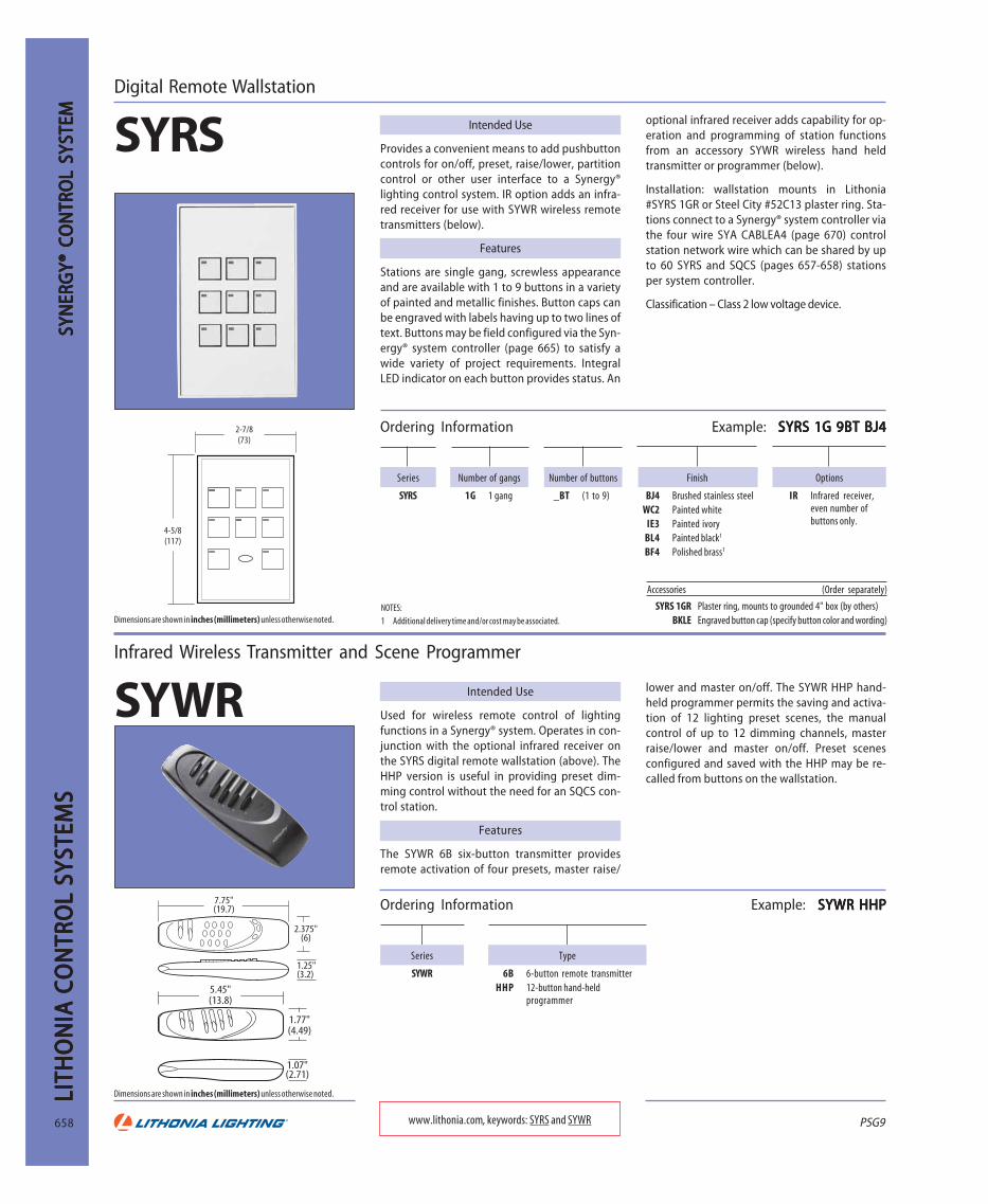
Ordering Information Example: SYRS 1G 9BT BJ4SYRS 1G 9BT BJ4SYRS 1G 9BT BJ4SYRS 1G 9BT BJ4SYRS 1G 9BT BJ4
Options
IR Infrared receiver,even number ofbuttons only.
Finish
BJ4 Brushed stainless steelWC2 Painted white
IE3 Painted ivoryBL4 Painted black1
BF4 Polished brass1
Accessories (Order separately)
SYRS 1GR Plaster ring, mounts to grounded 4" box (by others)BKLE Engraved button cap (specify button color and wording)
2-7/8(73)
4-5/8(117)
Dimensions are shown in inches (millimeters) unless otherwise noted.
www.lithonia.com, keywords: SYRS and SYWR
Ordering Information Example: SYWR HHP SYWR HHP SYWR HHP SYWR HHP SYWR HHP
Digital Remote Wallstation
SYRS Intended Use
Provides a convenient means to add pushbuttoncontrols for on/off, preset, raise/lower, partitioncontrol or other user interface to a Synergy®lighting control system. IR option adds an infra-red receiver for use with SYWR wireless remotetransmitters (below).
Features
Stations are single gang, screwless appearanceand are available with 1 to 9 buttons in a varietyof painted and metallic finishes. Button caps canbe engraved with labels having up to two lines oftext. Buttons may be field configured via the Syn-ergy® system controller (page 665) to satisfy awide variety of project requirements. IntegralLED indicator on each button provides status. An
Intended Use
Used for wireless remote control of lightingfunctions in a Synergy® system. Operates in con-junction with the optional infrared receiver onthe SYRS digital remote wallstation (above). TheHHP version is useful in providing preset dim-ming control without the need for an SQCS con-trol station.
Features
The SYWR 6B six-button transmitter providesremote activation of four presets, master raise/
Infrared Wireless Transmitter and Scene Programmer
SYWR
Number of gangs
1G 1 gang
SYN
ERG
Y® C
ON
TRO
L SY
STEM
SYN
ERG
Y® C
ON
TRO
L SY
STEM
SYN
ERG
Y® C
ON
TRO
L SY
STEM
SYN
ERG
Y® C
ON
TRO
L SY
STEM
SYN
ERG
Y® C
ON
TRO
L SY
STEM
Number of buttons
_BT (1 to 9)
Dimensions are shown in inches (millimeters) unless otherwise noted.
lower and master on/off. The SYWR HHP hand-held programmer permits the saving and activa-tion of 12 lighting preset scenes, the manualcontrol of up to 12 dimming channels, masterraise/lower and master on/off. Preset scenesconfigured and saved with the HHP may be re-called from buttons on the wallstation.
optional infrared receiver adds capability for op-eration and programming of station functionsfrom an accessory SYWR wireless hand heldtransmitter or programmer (below).
Installation: wallstation mounts in Lithonia#SYRS 1GR or Steel City #52C13 plaster ring. Sta-tions connect to a Synergy® system controller viathe four wire SYA CABLEA4 (page 670) controlstation network wire which can be shared by upto 60 SYRS and SQCS (pages 657-658) stationsper system controller.
Classification – Class 2 low voltage device.
7.75"(19.7)
2.375"(6)
1.25"(3.2)
1.77"(4.49)
1.07"(2.71)
5.45"(13.8)
Series
SYRS
NOTES:1 Additional delivery time and/or cost may be associated.

PSG9
LITHO
NIA
CON
TROL SYSTEM
SLITH
ON
IA CO
NTRO
L SYSTEMS
LITHO
NIA
CON
TROL SYSTEM
SLITH
ON
IA CO
NTRO
L SYSTEMS
LITHO
NIA
CON
TROL SYSTEM
S
659
Ordering Information Example: SYRS 1G 3BT BJ4 EXT SYRS 1G 3BT BJ4 EXT SYRS 1G 3BT BJ4 EXT SYRS 1G 3BT BJ4 EXT SYRS 1G 3BT BJ4 EXT
Type
EXT External inputs for occ. sensor and photocell, outputsfor LCPS and 0-10V dimming ballast.
Finish
BJ4 Brushed stainless steelWC2 Painted white
IE3 Painted IvoryBL4 Painted black1
BF4 Polished brass1
Series
SYRS
0-10V Dimming Wallstation
SYRS EXTDigital Equinox®
Intended Use
Ideal for applications which require manual andautomatic control of fluorescent or HID lightingequipped with compatible 4-wire (0-10V) elec-tronic dimming ballasts. Wall-mounted controlstation provides local on/off, manual dimmingand automated daylight dimming control in lo-calized applications. May be used as a stand-alone room controller or connected to a Syner-gy® system for timeclock control and integrationwith a building automation system.
Features
Microprocessor-based wallstation incorporatesone of the most advanced and easiest to configuredaylight harvesting algorithms in the industry.When used with Litronic® Series occupancy sen-sors (pages 672-673), all settings either adjust au-tomatically to actual room usage or are set at thestation, eliminating costly “ladder time” spent
Number of gangs
1G 1 gang
Number of buttons
Stand-alone3BT 3 buttons
Synergy®1BT 1 button3BT 3 buttons5BT 5 buttons7BT 7 buttons9BT 9 buttons
making adjustments on the sensors themselves.Local switching is provided by LPCS Series powerpack(s) (page 674), eliminating the need for homerun wiring back to panel mounted relays.
When connected to a Synergy® system, all sta-tion buttons, inputs and outputs are fully pro-grammable from the Synergy® controller or soft-ware and, like all Synergy® inputs and outputs,fully accessible to BACnet™ building automationsystems. This allows daylight harvesting and dim-ming to be fully integrated into the buildingcontrol system more simply and economicallythan ever before. Room switching and dimmingparameters can be easily incorporated into atime schedule, dimming preset, or progressiveload shedding strategy for maximum occupantcomfort and energy savings.
Classification – Class 2 low voltage device.
Line voltagebranch circuit
Line voltageto next room
Switched hot
SYRSEXT
DEQ APSphotocell
0-10V Dimming signal
Occupancy sensor
LPCSpowerpack
To next room(up to 60 max per MLX controller)
Synergy 'A4' network
(optional)
SYNERG
Y® CON
TROL SYSTEM
SYNERG
Y® CON
TROL SYSTEM
SYNERG
Y® CON
TROL SYSTEM
SYNERG
Y® CON
TROL SYSTEM
SYNERG
Y® CON
TROL SYSTEM
www.lithonia.com, keyword: SYRS EXT
NOTES:
1 Additional delivery time and/or cost may be associated.

PSG9
LITH
ON
IA C
ON
TRO
L SY
STEM
SLI
THO
NIA
CO
NTR
OL
SYST
EMS
LITH
ON
IA C
ON
TRO
L SY
STEM
SLI
THO
NIA
CO
NTR
OL
SYST
EMS
LITH
ON
IA C
ON
TRO
L SY
STEM
S
660
SYN
ERG
Y® C
ON
TRO
L SY
STEM
SYN
ERG
Y® C
ON
TRO
L SY
STEM
SYN
ERG
Y® C
ON
TRO
L SY
STEM
SYN
ERG
Y® C
ON
TRO
L SY
STEM
SYN
ERG
Y® C
ON
TRO
L SY
STEM
Ordering Information Example: SYRS 1G 4BT BJ4 EXTDS SYRS 1G 4BT BJ4 EXTDS SYRS 1G 4BT BJ4 EXTDS SYRS 1G 4BT BJ4 EXTDS SYRS 1G 4BT BJ4 EXTDS
Type
EXTDS External inputs for occ. sensor and photocell,two outputs for LCPS power packs.
Finish
BJ4 Brushed stainless steel, black buttonsWC2 Painted white, white buttons
IE3 Painted ivory, ivory buttonsBL4 Painted black, black buttons1
BF4 Polished brass, black buttons1
Series
SYRS
Dual Switch Wallstation
SYRS EXTDSDigital Equinox®
Intended Use
Ideal for applications which require manual andautomatic control of RT5™ fluorescent fixturesequipped with step-dimming ballasts, fluores-cent fixtures wired for inboard/outboard switch-ing or two independent lighting zones. Wall-mounted control station provides local manualcontrol with fully integrated occupancy sensorand photocell inputs for automated energy man-agement. May be used as a stand-alone roomcontroller or connected to a Synergy® system fortimeclock control and integration with a build-ing automation system.
Features
Microprocessor-based wallstation provides intui-tive manual control of bi-level lighting. Compati-ble with all Litronic® Series occupancy sensors(pages 672-673) for easy code compliance in a va-riety of applications.
Number of gangs
1G 1 gang
Number of buttons
Stand-alone4BT 4 buttons
Synergy®2BT 2 buttons4BT 4 buttons6BT 6 buttons9BT 9 buttons
Line voltagebranch circuit
Line voltageto next room
RT5 fixture with step dimming option
To next room(up to 60 max per MLX controller)
Synergy 'A4' network
(optional)
Switched leg 'S1'
Switched leg 'S2'
SYRSEXT DS
Qty.2LPCSpowerpacks
DEQ APSphotocell
Occupancy sensor
Use LPCS Series power packs (page 674) to switchup to two full 20A circuits on each zone, elimi-nating the need for home run wiring back topanel mounted relays.
When connected to a Synergy® system, all sta-tion buttons, inputs and outputs are fully pro-grammable from the Synergy® controller or soft-ware and, like all Synergy® inputs and outputs,fully accessible to BACnet™ building automationsystems. This allows daylight harvesting and re-mote switching to be fully integrated into thebuilding control system more simply and eco-nomically than ever before. Relays and buttons ineach room can be easily incorporated into a timeschedule, dimming preset or progressive loadshedding strategy for maximum occupant com-fort and energy savings.
Classification – Class 2 low voltage device.
NOTES:1 Additional delivery time and/or cost may be associated.
www.lithonia.com, keyword: SYRS EXTDS

PSG9
LITHO
NIA
CON
TROL SYSTEM
SLITH
ON
IA CO
NTRO
L SYSTEMS
LITHO
NIA
CON
TROL SYSTEM
SLITH
ON
IA CO
NTRO
L SYSTEMS
LITHO
NIA
CON
TROL SYSTEM
S
661www.lithonia.com, keywords: DEQ LC and DEQ APS
Digital Equinox® Load Controller
Intended Use
Integrates a localized zone of fluorescent light-ing equipped with compatible four-wire elec-tronic dimming ballasts into a Synergy® system.Plenum-mounted DEQ LC load controller pro-vides on/off, dimming and automated daylightdimming control for a single lighting zone whena wall-mounted control station is not desired.
Features
The DEQ LC installs in the plenum above thearea to be controlled in place of the cover on astandard 4” or 5” square junction box.
DEQ LC load controller acts as a hub for the con-nection of the low voltage DEQ APS photocell(below), Litronic® occupancy sensor (pages 672-673), LPCS power control station (page 674) and0-10V dimmable ballast control leads. If de-sired, a standard wall switch can be used for lo-
Intended Use
Low voltage sensor used to provide ambientlight level information to Digital Equinox® loadcontroller or wallstations for indoor daylightharvesting applications.
Features
This speciality photosensor is factory calibratedto accommodate the relatively low light levelsnormally found on the ceiling in office applica-tions. 360° lens allows the sensor to averagethe room light level, reducing the effect of re-
DEQ LCDigital Equinox®
Ordering Information Example: DEQ APS INDEQ APS INDEQ APS INDEQ APS INDEQ APS IN
Mounting
IN Indoor
Series
DEQ APS Digital Equinox® analogphotosensor
Options
CNPY Canopy mount to a 4" square junctionbox.
Ordering Information Example: DEQ LC DEQ LC DEQ LC DEQ LC DEQ LC
Series
DEQ LC Digital Equinox® load controller
Analog Photosensor
DEQ APSDigital Equinox®
1.28"(3.25)
1.15"(2.9)
SYNERG
Y® CON
TROL SYSTEM
SYNERG
Y® CON
TROL SYSTEM
SYNERG
Y® CON
TROL SYSTEM
SYNERG
Y® CON
TROL SYSTEM
SYNERG
Y® CON
TROL SYSTEM
cal on/off operation making the control systemtotally unobtrusive to the user.
When connected to a part of a Synergy® system,the DEQ LC can share status, set point and over-ride functions with all Synergy® system control-lers, PC graphics and other building control sys-tems through the BACnet™ protocol.
Dimensions are shown in inches (millimeters) unless otherwise noted.
flective or lightly colored items brought into theroom or placed on a desk.
Classification – Class 2 low voltage device.

PSG9
LITH
ON
IA C
ON
TRO
L SY
STEM
SLI
THO
NIA
CO
NTR
OL
SYST
EMS
LITH
ON
IA C
ON
TRO
L SY
STEM
SLI
THO
NIA
CO
NTR
OL
SYST
EMS
LITH
ON
IA C
ON
TRO
L SY
STEM
S
662
Low Voltage Momentary Switch
LVMSWPM
Ordering Information Example: LVMS PILOT WH LVMS PILOT WH LVMS PILOT WH LVMS PILOT WH LVMS PILOT WH
(blank) Standard switchPILOT Pilot light switch
KEY Key operated switch
Color
IV IvoryWH White
Low Voltage Decora® Switch
LVDSDSA FP
Series
LVMS
Ordering Information Example: LVDS WH LVDS WH LVDS WH LVDS WH LVDS WH
SSPLSweepSwitch®
handle is lighted for easy location in the dark.
Wires to a 120V or 277V circuit switched by aSynergy® or SwitchPak® relay panel like a stan-dard toggle switch, is not line/load sensitive anddoes not require a neutral connection.
Strap-mount device; mounts in a standard singlegang switch box and uses a standard toggleopening wallplate (not included).
Listings
UL Listed. CSA Certified.
Intended Use
Provides individual local line voltage overridecontrol of lighting in time-based controlschemes. Can be used manually to turn lightingon and off in the normal manner. Resets itself au-tomatically to the off position in response to aprogrammed power interruption signal provid-ed by the lighting control panel.
Works like a standard wall switch for on/off oper-ation. Automatically resets to off when power isremoved for approximately five seconds. Switch
Ordering Information Example: SSPL 05 277 SSPL 05 277 SSPL 05 277 SSPL 05 277 SSPL 05 277
Series
SSPL
Voltage
277 120V or 277V (dual voltage)
Load amperage
0 5 0.1 to 5.0 amps2 0 1.0 to 20 amps
Series
DSA FP
Number of openings
D_ 1 to 6
Ordering Information Example: DSA FP D1 WH DSA FP D1 WH DSA FP D1 WH DSA FP D1 WH DSA FP D1 WH
Series
LVDS
NOTES:1 Additional delivery time and/or cost may be associated with these premium
colors.
WH WhiteIV Ivory
Series
WPM
Finish
BS Brushed stainlessWH Painted white
IV Painted ivory
Number of openings
_MS 1 to 202
Number of gangs
_G 1 to 101
Options
LE Customlabeling3
www.lithonia.com, keywords: LVMS, LVDS and SSPL
SYN
ERG
Y® C
ON
TRO
L SY
STEM
SYN
ERG
Y® C
ON
TRO
L SY
STEM
SYN
ERG
Y® C
ON
TRO
L SY
STEM
SYN
ERG
Y® C
ON
TRO
L SY
STEM
SYN
ERG
Y® C
ON
TRO
L SY
STEM wire connections. Wallplates are offered in a va-
riety of sizes and configurations and may be en-graved with customer-supplied labels. Use withSynergy® or SwitchPak® lighting control panels.
Classification – Class 2 low voltage device.
Intended Use
Lithonia LVMS switches and WPM wallplates pro-vide a durable and attractive solution for config-uring low voltage control switch assemblies.Switches snap-fit into the wallplates and are sup-plied with push-on connectors for low voltage
NOTES:
1 Plates larger than four gangs may have longer lead times.2 Must equal the number of gangs (one switch per gang) or two times the number
of gangs (two switches per gang).
3 Two lines, seven characters per line for two switches per gang plate or two lines,12 characters per line for one switch per gang plate.
ganged with other Decora® style devices. DSAwallplates are offered in a variety of sizes andfinishes. Use with Synergy® or SwitchPak® light-ing control panels.
Classification – Class 2 low voltage device.
FILLER Snap-in blank fillerPILOT KEY Key-operated switch
with pilot
Options
Intended Use
Lithonia LVDS switches and DSA wallplates pro-vide a durable and attractive low voltage switchsolution with a standard strap-mount form fac-tor and designer styling. Switches may be
Color
GY Gray1
BK Black1
WH WhiteIV Ivory
Color
Ordering Information Example: WPM 1G 4MS WH WPM 1G 4MS WH WPM 1G 4MS WH WPM 1G 4MS WH WPM 1G 4MS WH
GY Gray1
BK Black1
AL Almond1
AL Almond1
BR Brown1

PSG9
LITHO
NIA
CON
TROL SYSTEM
SLITH
ON
IA CO
NTRO
L SYSTEMS
LITHO
NIA
CON
TROL SYSTEM
SLITH
ON
IA CO
NTRO
L SYSTEMS
LITHO
NIA
CON
TROL SYSTEM
S
663
Intended Use
A unique lighting control system that integratesall aspects of lighting control into a single systemplatform. Combines architectural dimming, lowvoltage switching, lighting automation and ener-gy management functions into a single scalablepackage capable of meeting the requirements ofvirtually any lighting control application.
Features
Combines the most popular aspects of lightingautomation with full-featured low voltageswitching and architectural dimming functions.
Switching and dimming functions may be con-trolled manually or scheduled on a weekly or cal-endar date basis. Functions may be set up usingthe integral LCD alphanumeric display and key-pad or through the use of a personal computer
Synergy® Lighting Control System
Synergy®
www.lithonia.com, keyword: Synergy
Series
SYES Small enclosure,2 modules max.
SYEM Mediumenclosure, 4modules max.
SYEL Large enclosure,6 modules max.
SYESB Small enclosurewith breakerdoor, 2 modulesmax.
SYEMB Mediumenclosure withbreaker door, 4modules max.
SYELB Large enclosurewith breakerdoor, 6 modulesmax.
Main feed options
(blank) No tap feedlugs, nomainbreaker
ML Tap-feedlugs forpowering upto fourcabinetsfrom asingle mainfeed.Requires 2modulepositions;requirespowermoduleswith circuitbreakers
MB_ Mainbreaker, 3pole, specify# of amps
NBAR 42 circuitneutral bar
Options
(blank) Panel ships ascomponentsconsisting ofenclosure, powermodules andcontroller
FA Panel ships fullyassembled(controller andrelay modulesfactory-installedin enclosure)
DMX Dimminginterface requiredfor connection toDMX512 control
PHONE Telephoneinterface1
RO Remote override,accepts contactclosure to forceall relays to full-on for essentiallightingapplications2
OS Occupancy sensorcompatible inputsfor dry contactswitches oroccupancysensors3
LEGACY Allows control oflegacy MiniPac®,Sequel® andMaxStar®dimmer cabinets1
_DB1 Qty. 120V 2KW dimmers with six20A circuit breakers, six dimmersper module
_DB2 Qty. 277V 3.5KW dimmers withfour 20A circuit breakers, sixdimmers per module
_DB3 Qty. 120V 1.5KW dimmers withsix 15A circuit breakers, sixdimmers per module
_DB4 Qty. 277V 3.3KW dimmers withfour 15A circuit breakers, sixdimmers per module
_R Qty. single pole, 120/277 20A,eight relays per module
_RB1 Qty. single pole 20A relays, six120V, 20A circuit breakers, eightrelays per module
_RB2 Qty. single pole 20A relays, four277V, 20A circuit breakers, eightrelays per module
_RB3 Qty. single pole 20A relays, six120V, 15A circuit breakers, eightrelays per module
_RB4 Qty. single pole 20A relays, four277V, 15A circuits, eight relaysper module
_CB2 Qty. 277V constant breakers, fourbreakers per module
_CB1 Qty. 120V constant breakers, sixbreakers per module
_HB6 Qty. single pole 20A relays, four347V, 20A circuit breakers, eightrelays per module
_HB7 Qty. single pole 20A relays, four347V, 15A circuit breakers, eightrelays per module
Output quantity/type Controller type
MLC Basiccontrollerfor stand-alone paneloperation
MLX Enhancedcontrollerfornetworkpaneloperation
SCP Secondarypanel, lesscontroller
NOTES:
1 Not available with MLC controller.
2 Only required for _R and RB output types. All other modules come standardwith RO option.
3 Only required for _R and _RB output types. All other modules come standardwith OS option. RO option included when OS option specified.
Ordering Information Example: SYELB 16RB1 18DBI MLX NBAR DMX SYELB 16RB1 18DBI MLX NBAR DMX SYELB 16RB1 18DBI MLX NBAR DMX SYELB 16RB1 18DBI MLX NBAR DMX SYELB 16RB1 18DBI MLX NBAR DMX
SYNERG
Y® CON
TROL SYSTEM
SYNERG
Y® CON
TROL SYSTEM
SYNERG
Y® CON
TROL SYSTEM
SYNERG
Y® CON
TROL SYSTEM
SYNERG
Y® CON
TROL SYSTEM
with optional software (page 656).
Panels can operate individually as stand-alonelighting controllers or optionally in a networkconfiguration with distributed intelligence. Achoice of system controllers (page 665) allowscustomization to best meet the requirementsand budget of each project.
Provides capacity for a maximum of 48 relays or30 dimmers per enclosure (pages 666-669). En-closures can operate in a master/secondary con-figuration, providing control of up to 96 outputsfrom a single controller. Relays and dimmers areeach rated for control of one lighting circuit atthe listed voltage.
Listings
UL Listed to US and Canadian safety standards.California Title 24 certified.
Accessories (Order separately)
SYA SRE Recess kit for small enclosuresSYA MRE Recess kit for medium enclosuresSYA LRE Recess kit for large enclosuresLSA DOC Job specific submittal and documentation
_F Qty. 0-10V dimmers with single-pole 20A relays, suitable for 120/277V, eight relays and dimmersper module
_FH Qty. 0-10V dimmers with single-pole 20A relays, suitable for 120/277 and 347V, eight relays anddimmers per module
_FB1 Qty. 0-10V dimmers with single20A relays, six 120V, 20A circuitbreakers, eight relays anddimmers per module
_FB2 Qty. 0-10V dimmers, single pole20A relays, four 277V, 20A circuitbreakers, eight relays anddimmers per module
_FB3 Qty. 0-10V dimmers, single pole20A relays, six 120V, 15A circuitbreakers, eight relays anddimmers per module
_FB4 Qty. 0-10V dimmers, single pole20A relays, four 277V, 15A circuitbreakers, eight relays anddimmers per module
_FB6 Qty. 0-10V dimmers, single pole20A relays, four 347V, 20A circuitbreakers, eight relays anddimmers per module
_FB7 Qty. 0-10V dimmers, single pole20A relays, four 347V, 20A circuitbreakers, eight relays anddimmers per module
_ H Qty. single pole 20A relayssuitable for 120V, 277V or 347Voperation, eight relays permodule
PSG9
LITH
ON
IA C
ON
TRO
L SY
STEM
SLI
THO
NIA
CO
NTR
OL
SYST
EMS
LITH
ON
IA C
ON
TRO
L SY
STEM
SLI
THO
NIA
CO
NTR
OL
SYST
EMS
LITH
ON
IA C
ON
TRO
L SY
STEM
S
664
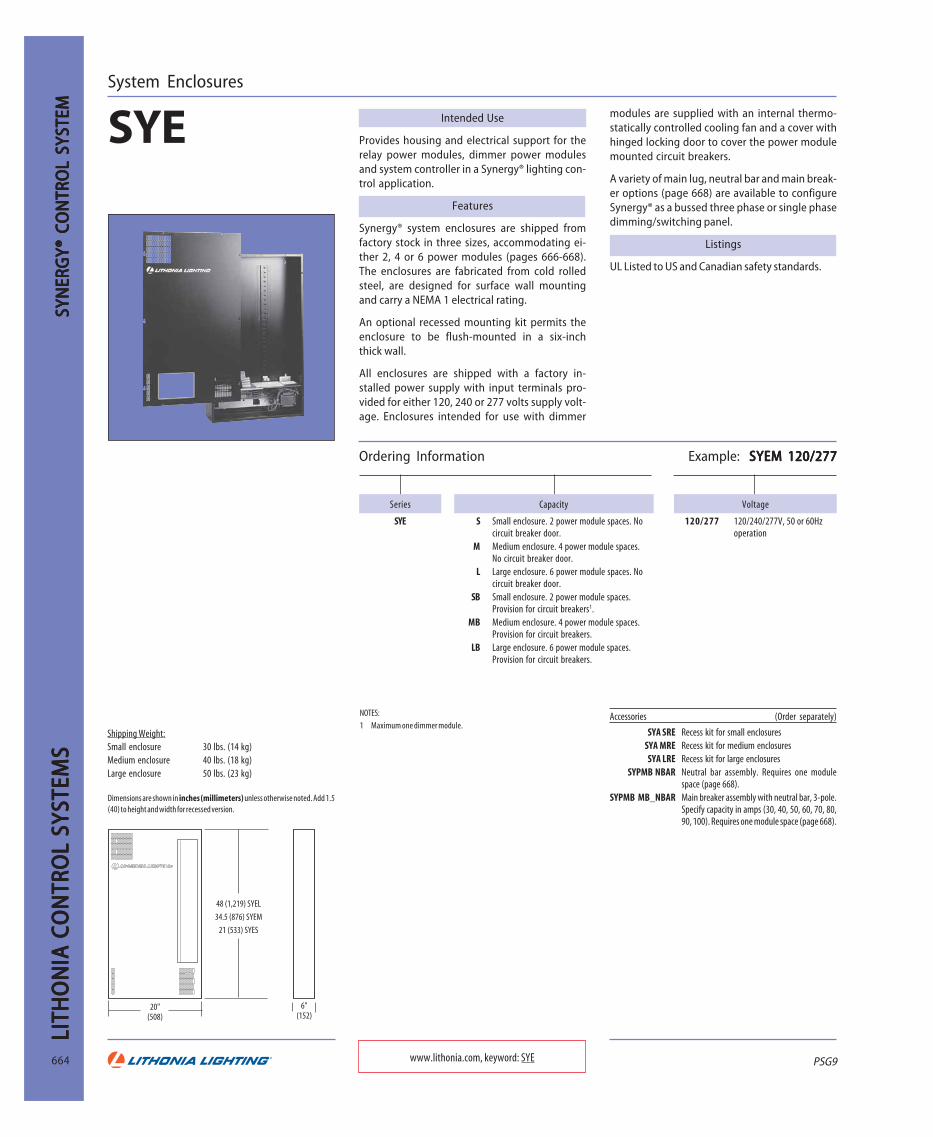
System Enclosures
SYE
Ordering Information Example: SYEM 120/277SYEM 120/277SYEM 120/277SYEM 120/277SYEM 120/277
Capacity
S Small enclosure. 2 power module spaces. Nocircuit breaker door.
M Medium enclosure. 4 power module spaces.No circuit breaker door.
L Large enclosure. 6 power module spaces. Nocircuit breaker door.
SB Small enclosure. 2 power module spaces.Provision for circuit breakers1.
MB Medium enclosure. 4 power module spaces.Provision for circuit breakers.
LB Large enclosure. 6 power module spaces.Provision for circuit breakers.
Voltage
120/277 120/240/277V, 50 or 60Hzoperation
Series
SYE
NOTES:
1 Maximum one dimmer module.Shipping Weight:Small enclosure 30 lbs. (14 kg)Medium enclosure 40 lbs. (18 kg)Large enclosure 50 lbs. (23 kg)
Accessories (Order separately)
SYA SRE Recess kit for small enclosuresSYA MRE Recess kit for medium enclosuresSYA LRE Recess kit for large enclosures
SYPMB NBAR Neutral bar assembly. Requires one modulespace (page 668).
SYPMB MB_NBAR Main breaker assembly with neutral bar, 3-pole.Specify capacity in amps (30, 40, 50, 60, 70, 80,90, 100). Requires one module space (page 668).
Dimensions are shown in inches (millimeters) unless otherwise noted. Add 1.5(40) to height and width for recessed version.
www.lithonia.com, keyword: SYE
Intended Use
Provides housing and electrical support for therelay power modules, dimmer power modulesand system controller in a Synergy® lighting con-trol application.
Features
Synergy® system enclosures are shipped fromfactory stock in three sizes, accommodating ei-ther 2, 4 or 6 power modules (pages 666-668).The enclosures are fabricated from cold rolledsteel, are designed for surface wall mountingand carry a NEMA 1 electrical rating.
An optional recessed mounting kit permits theenclosure to be flush-mounted in a six-inchthick wall.
All enclosures are shipped with a factory in-stalled power supply with input terminals pro-vided for either 120, 240 or 277 volts supply volt-age. Enclosures intended for use with dimmer
SYN
ERG
Y® C
ON
TRO
L SY
STEM
SYN
ERG
Y® C
ON
TRO
L SY
STEM
SYN
ERG
Y® C
ON
TRO
L SY
STEM
SYN
ERG
Y® C
ON
TRO
L SY
STEM
SYN
ERG
Y® C
ON
TRO
L SY
STEM modules are supplied with an internal thermo-
statically controlled cooling fan and a cover withhinged locking door to cover the power modulemounted circuit breakers.
A variety of main lug, neutral bar and main break-er options (page 668) are available to configureSynergy® as a bussed three phase or single phasedimming/switching panel.
Listings
UL Listed to US and Canadian safety standards.
20"(508)
6"(152)
48 (1,219) SYEL
34.5 (876) SYEM
21 (533) SYES

PSG9
LITHO
NIA
CON
TROL SYSTEM
SLITH
ON
IA CO
NTRO
L SYSTEMS
LITHO
NIA
CON
TROL SYSTEM
SLITH
ON
IA CO
NTRO
L SYSTEMS
LITHO
NIA
CON
TROL SYSTEM
S
665
Intended Use
Provides user interface, display, clock and logiccircuits for a Synergy® lighting control systemenclosure and a means to set up lighting controlfunctions, including manual switching, manualand preset dimming, schedules, astronomic timecontrol, photocell switching and daylighting.
Features
Constructed as a plug-in chassis to enhance initialinstallation and serviceability. Used to set up andsave operational features of the system. Providessupport for external control devices (Synergy®digital remote stations (page 658), Sequel® pre-set dimming control stations (page 657), DigitalEquinox® devices (page 659-660) and legacy dim-mer cabinets (page 676) (optional).
User interface is designed for simple operationusing the soft key format popular on automatedteller machines. Large back-lit display providestext-based prompting and feedback for menu
System Controllers
SYSC
Ordering Information Example: SYSC MLXSYSC MLXSYSC MLXSYSC MLXSYSC MLX
Accessories (Order separately)
SYA SKIT Permits two SYE enclosures to operate with asingle controller.
SYSW CONFIG WindowsTM configuration software and cable(page 656).2
SYA CABLEA4 Class 2, four-conductor, plenum-rated networkcable (page 670).
SYA CABLES2 Lithonia plenum-rated RS485 network cable2
(page 670).
Options
ISA Three 16-bit ISA expansion slotsPHONE Telephone interface for voice-prompted override and remote modem access (requires ISA option)1
DMX Theatrical dimming interface, required for connection to DMX512 control signalLEGACY Allows control of one complete network (255 dimmers) of legacy MiniPac®, Sequel® and Max-
Star® dimmer cabinets. Replaces master controller on existing systems.
Shipping Weight is 5.5 lbs. (2.5 kg).
Functional
NOTES:
1 No voice-prompted override with SYSC MLC.2 Not available with SYSC MLC.
Controller type
MLC Basic system controllerMLX Network system controller
www.lithonia.com, keyword: SYSC
Soft Function Keys
4-line 80-character LCDDisplay with Backlight
System StatusLED Indicators
Navigation Keys
DB9 Serial Port
SYNERG
Y® CON
TROL SYSTEM
SYNERG
Y® CON
TROL SYSTEM
SYNERG
Y® CON
TROL SYSTEM
SYNERG
Y® CON
TROL SYSTEM
SYNERG
Y® CON
TROL SYSTEM
navigation as well as status, diagnostic informa-tion and alarms.
Astronomic feature built into Synergy’s internalclock will calculate sunrise and sunset times foruse in the lighting schedules. The controller alsocan read values from accessory photocells andprovide automatic switching or dimming oflighting based on the ambient light level.
See the matrix below for additional features andcapacities specific to the controller type selected.
Series
SYSC
Features Selection Matrix
System Function MLC Controller MLX ControllerRelay Capacity 48 48 (96 total with(No breakers) secondary cabinet)Relay Capacity 40 40 (80 total with
(With breakers) secondary cabinet)
Dimmer Capacity 30 30 (60 total withsecondary cabinet)
DMX channel-to-output DMX channel-to-outputDMX512 Input configured via configured via
hardware settings controller software
Scheduling 11 schedules, 100 schedules,99 events unlimited events
Analog Inputs YES YESPC Support YES YESScript Logic NO YES
Logging NO YESPriority Logic NO YES
Ethernet Network NO YESARCNET Network NO YES
Telephone Override NO YES, optionalBACnet® NO YES
RS232 YES YESModem YES, optional YES, optional
Sequel® Stations YES YESLegacy Dimmers NO YES, optionalDigital Remotes YES YES

PSG9
LITH
ON
IA C
ON
TRO
L SY
STEM
SLI
THO
NIA
CO
NTR
OL
SYST
EMS
LITH
ON
IA C
ON
TRO
L SY
STEM
SLI
THO
NIA
CO
NTR
OL
SYST
EMS
LITH
ON
IA C
ON
TRO
L SY
STEM
S
666 www.lithonia.com, keywords: SYPM and SYPMB 6D
NOTES:
1 Only available with SYPMB 8H module.2 RO option is standard for all modules with OS option; RO and OS options are
standard for 8H modules.
Relay Power Modules
SYPM 8RSYPM 8H
Intended Use
Used in conjunction with system enclosure andcontroller (pages 664-665) to provide manualand automatic on/off control of all types of light-ing loads. Combine with line voltage dimmer(below), 0-10V and DALI (page 667) modules tocreate a complete lighting control solution forany application.
Features
Modules include eight 20A relays and are avail-able for 120V to 277V and 120V to 347V appli-cations. Unique zero-cross switching technolo-gy minimizes the destructive effects of switch-ing large high-inrush loads, such as electronicfluorescent and HID. All relay module typesmay be ordered with optional 15A or 20Abranch circuit breakers.
Line Voltage Dimmer Power Module
SYPMB 6DIntended Use
Used in conjunction with system enclosure andcontroller (pages 664-665) to provide manualand automatic on/off and line voltage dimmingcontrol of a wide variety of lighting loads. Com-bine with relay (above), 0-10V and DALI (page667) modules to create a complete lighting con-trol solution for any application.
Features
Modules include six 20A line voltage dimmerswith integral 15A or 20A circuit breakers and areavailable for 120V, 230V and 277V applications.Each dimmer is equipped with an air-gap relayand an architectural-grade toriodal filter.
All digital design ensures smooth, dependable
Shipping weight is 4lbs. (1.9kg) without breakers and 9lbs. (4.1kg) with breakers.
Ordering Information Example: SYPM 8R SYPM 8R SYPM 8R SYPM 8R SYPM 8R
Type
8R Relay module with eight single-pole20A relays for 120 or 277Voperation
8 H Relay module with eight single-pole20A relays for 120, 277 or 347Voperation
Series
SYPM Module for use with externalcircuit breakers
SYPMB Module with circuit breakers
Options2
RO Remote override. Acceptscontact closure to force allrelays on in essential lightingapplications
OS Occupancy sensor. Eight lowvoltage inputs for contactswitches or occupancy sensors.
Circuit breakers/voltage
(blank) No circuit breakersB1 Six 20A, 120V, 10KAIC breakersB2 Four 20A, 277V, 14KAIC breakersB3 Six 15A, 120V, 10KAIC breakersB4 Four 15A, 277V, 14KAIC breakersB6 Four 20A, 347V, 14KAIC breakers1
B7 Four 15A, 347V, 14KAIC breakers1
Ordering Information Example: SYPMB 6DB1 SYPMB 6DB1 SYPMB 6DB1 SYPMB 6DB1 SYPMB 6DB1
Series
SYPMB
Dimmers
6D Six dimmers per module
Circuit breakers/voltage
B1 Six 20A, 120V, 10 KAIC breakersB2 Four 20A, 277V, 14 KAIC breakersB3 Six 15A, 120V, 10 KAIC breakersB4 Four 15A, 277V, 14 KAIC breakersB5 Four 20A, 120V, 65KAIC breakersShipping weight is 22lbs. (10kg).
SYN
ERG
Y® C
ON
TRO
L SY
STEM
SYN
ERG
Y® C
ON
TRO
L SY
STEM
SYN
ERG
Y® C
ON
TRO
L SY
STEM
SYN
ERG
Y® C
ON
TRO
L SY
STEM
SYN
ERG
Y® C
ON
TRO
L SY
STEM Modules are equipped with a pilot light output
for each relay, eight low voltage contact switchinputs (see page 662 for available switches) andtwo analog inputs (see page 670 for photocells).Switch inputs on units ordered with the "OS" op-tion are compatible for direct connection to oc-cupancy sensors (pages 672-673). All inputs arefully configurable through the use of a systemcontroller (page 665) to work with a wide varietyof input devices and control any combination ofsystem relays and dimmers. Once configured, allmodule settings are stored locally and the mod-ule will continue to operate in fail-safe modeeven if the system controller is removed fromthe system.
Listings
UL Listed to US and Canadian safety standards.
performance without field calibration. Uniquecombination of analog circuitry and digital signalprocessing techniques minimize the effects ofpoor power quality and prevent noticeable flick-er and drift.
Individual dimmer response curves are field con-figurable to accommodate most lamp and ballasttypes via the system controller (page 665). Onceconfigured, all module settings are stored local-ly and the module will continue to operate infail-safe mode even if the system controller is re-moved from the system.
Listings
UL Listed to US and Canadian safety standards.

PSG9
LITHO
NIA
CON
TROL SYSTEM
SLITH
ON
IA CO
NTRO
L SYSTEMS
LITHO
NIA
CON
TROL SYSTEM
SLITH
ON
IA CO
NTRO
L SYSTEMS
LITHO
NIA
CON
TROL SYSTEM
S
667www.lithonia.com, keywords: SYPM 8F and SYPM DALI
Shipping weight is 4lbs. (1.9kg) without breakers and 9lbs. (4.1kg) with breakers.
Ordering Information Example: SYPM 8F SYPM 8F SYPM 8F SYPM 8F SYPM 8F
Type
8F Ballast module with eightsingle-pole, 20A relays andeight 0-10VDC analog outputs
Series
SYPM Module for use with externalcircuit breakers
SYPMB Module with circuit breakers
(blank) No circuit breakers suitable for 120V or277V operation
H No circuit breakers suitable for 120, 277or 347V operation
B1 Six 20A, 120V, 10KAIC circuit breakers
Ordering Information Example: SYPM DALI SYPM DALI SYPM DALI SYPM DALI SYPM DALI
Series
SYPM DALI Network controller and power supply for three DALI loops
Shipping weight is 4lbs. (1.8kg).
0-10V Fluorescent Dimmer Power Module
SYPM 8FIntended Use
Used in conjunction with system enclosure andcontroller (pages 664-665) to provide manualand automatic on/off and 0-10V dimming con-trol of compatible four-wire fluorescent andnon-dim loads. Combine with DALI (below), re-lay and line voltage dimmer (page 666) mod-ules to create a complete lighting control solu-tion for any application.
Features
Modules include eight 20A relays and 0-10VDCoutputs for dimming ballast control, are avail-able for 120V to 277V or 120V to 347V applica-tions and may be ordered with optional 15A or20A branch circuit breakers. Unique zero-crossswitching technology minimizes the destructiveeffects of switching high-inrush loads. Each 0-
Circuit breakers/voltage
DALI Fluorescent Control Power Module
SYPM DALIIntended Use
Used in conjunction with system enclosure andSYSC MLX controller (pages 664-665) to providemanual and automatic control of compatible de-vices on a DALI network. Combine with 0-10V(above), relay and line voltage dimmer (page666) modules to create a complete lighting con-trol solution for any application.
Features
Module includes network controllers and powersupplies for three DALI networks (loops) of up to64 devices each. Connected DALI devices may beconfigured via the system controller (page 665)for status monitoring and prioritized control byany Synergy® user interface, timeclock schedule
SYNERG
Y® CON
TROL SYSTEM
SYNERG
Y® CON
TROL SYSTEM
SYNERG
Y® CON
TROL SYSTEM
SYNERG
Y® CON
TROL SYSTEM
SYNERG
Y® CON
TROL SYSTEM
10V output may be used to control up to 50 com-patible four-wire ballasts. Modules are equippedwith two analog inputs (see page 670) for photo-cells) and eight low voltage inputs suitable fordry contact switches (page 662) and occupancysensors (pages 672-673). All inputs are fully con-figurable through the use of a system controller(page 665) to work with a wide variety of inputdevices and control any combination of systemrelays and dimmers. Once configured, all modulesettings are stored locally and the module willcontinue to operate in fail-safe mode even if thesystem controller is removed from the system.
Listings
UL Listed to US and Canadian safety standards.
B2 Four 20A, 277V, 14KAIC circuit breakersB3 Six 15A, 120V, 10KAIC circuit breakersB4 Four 15A, 277V, 14KAIC circuit breakersB6 Four 20A, 347V, 14KAIC circuit breakersB7 Four 15A, 347V, 14KAIC circuit breakers
or graphical workstation.
Listings
UL Listed to US and Canadian safety standards.

PSG9
LITH
ON
IA C
ON
TRO
L SY
STEM
SLI
THO
NIA
CO
NTR
OL
SYST
EMS
LITH
ON
IA C
ON
TRO
L SY
STEM
SLI
THO
NIA
CO
NTR
OL
SYST
EMS
LITH
ON
IA C
ON
TRO
L SY
STEM
S
668
Ordering Information Example: SYPMB NBARSYPMB NBARSYPMB NBARSYPMB NBARSYPMB NBAR
Neutral Bar and Main Breaker Modules
SYPMB NBAR
SYPMB MB_NBAR
Intended Use
Used in conjunction with system enclosure (page664) and power modules equipped with branchcircuit breakers (pages 666 and 667) to facilitateconnection of an individual Synergy® cabinet toa three-phase, four-wire or single-phase, three-wire main feed.
Features
Modules include a 42 circuit neutral bar ratedfor a #6 to 2/0 AWG main feed and #14 to #4AWG branch neutral conductors. The neutral barcan be used in 120V, 277V or 347V applications.
The optional main breaker is available in capaci-ties up to 100A and is rated for 120V/240V, 120/208V and 277/480V feeds and conductor sizesup to 2/0 AWG.
Listings
UL Listed to US and Canadian safety standards.
Series
SYPMB
Main breaker
(blank) No main breakerMB_ Main breaker, 3 pole, indicate capacity:
30, 40, 50, 60, 70, 80, 90 or 100 amps
Tap Feed Modules
SYPMB ML
SYPMB MB_ML
SYPMB MN
Intended Use
Used in conjunction with system enclosures(page 664) and power modules equipped withbranch circuit breakers (pages 666 and 667) tofacilitate connection of up to four Synergy® cab-inets to a single three-phase, four-wire or sin-gle-phase, three-wire main feed.
Features
ML modules include a three position power dis-tribution block and optional main breaker. MNmodules include a single position power distri-bution block and a 42 circuit neutral bar. All dis-tribution positions include one main lug ratedfor a single #4 AWG to 500 kcmil conductor andfour tap lugs rated for a single #14 to 2/0 AWGconductor each.
One ML module and one MN module is requiredfor each application. All units are rated for 120V/240V, 120/208V and 277/480V applications.
Listings
UL Listed to US and Canadian safety standards.
Ordering Information Example: SYPMB MLSYPMB MLSYPMB MLSYPMB MLSYPMB ML
Series
SYPMB
Distribution lugs
ML Phase conductor tap feed lugs, 3 positionMN Neutral conductor tap feed lug with 42
circuit neutral bar
Main breaker
(blank) No main breakerMB_ Main breaker, 3 pole, indicate capacity:
30, 40, 50, 60, 70, 80, 90 or 100 amps
www.lithonia.com, keyword: SYPMB
Shipping weights are 5 lbs. (2.3 kg) without main breaker and 8 lbs. (3.6 kg) withmain breaker.
SYN
ERG
Y® C
ON
TRO
L SY
STEM
SYN
ERG
Y® C
ON
TRO
L SY
STEM
SYN
ERG
Y® C
ON
TRO
L SY
STEM
SYN
ERG
Y® C
ON
TRO
L SY
STEM
SYN
ERG
Y® C
ON
TRO
L SY
STEM
54 Dimmer, 3 Phase, 4 Wire Tap Feed Example
3 Phase, 4 Wire Main Feed Conductors 500 kcmil Maximum
Tap Feed Conductors 2/0 AWG Maximum
SYPMB NBAR
SYPMB ML
SYPMB MN
Neutral bar
NBAR Neutral bar, 42 circuit
18 Dimmer, 3 Phase, 4 Wire Example
3 Phase, 4 Wire Main Feed Conductors 2/0 AWG Maximum
SYPMB NBAR

PSG9
LITHO
NIA
CON
TROL SYSTEM
SLITH
ON
IA CO
NTRO
L SYSTEMS
LITHO
NIA
CON
TROL SYSTEM
SLITH
ON
IA CO
NTRO
L SYSTEMS
LITHO
NIA
CON
TROL SYSTEM
S
669www.lithonia.com, keyword: Synergy
Ordering Information Example: SYBP42 P2 225 ML B SS MLX PHONE SYBP42 P2 225 ML B SS MLX PHONE SYBP42 P2 225 ML B SS MLX PHONE SYBP42 P2 225 ML B SS MLX PHONE SYBP42 P2 225 ML B SS MLX PHONE
Accessories (Order separately)
LSA DOC Job specific submittal and documentation.SYSW CONFIG WindowsTM 95/98, 2000, NT or XP configuration soft-
ware and cable (page 656).________ Order branch circuit breakers separately. See
Branch Circuit Breaker Selection Table.
NOTES:
1 Order branch circuit breakers separately. See selection table at below.
2 Consult factory for additional main breaker selections and interrupt ratings.3 For house lighting control only.
4 Not available with MLC or SCP controllers.
5 Must provide panel schedules.
Series
SYBP18 18-polecapacity1
SYBP30 30-polecapacity1
SYBP42 42-polecapacity1
Main feed options2
ML Main lugMB100 100A main
breakerMB225 225A main
breakerMB400 400A main
breaker
Voltage
P1 120/208VP2 277/480V
Maximum rating
100 100 amps225 225 amps400 400 amps
Options
DMX Interface forconnection toDMX512 control3,4
PHONE Telephoneinterface4
LVIN Eight low voltageswitch and twoanalog inputs
FA Factory-assembledinterior withbreakers andcontrollers5
LEGACY Interface to allowcontrol of up to 62MiniPac®distributed dimmerpacks
Controller type
MLC Basic controllerfor stand-alonepanel operation.
MLX Enhancedcontroller fornetwork paneloperation.
SCP Secondary panel,less controller
Door type/mounting
SS Standard surfaceDS Door-in-door
surfaceSF Standard flush
Synergy® Controllable Breaker Panel
Synergy®Intended Use
Ideal for applications requiring circuit level re-mote control or lighting automation. Combinesthe powerful capabilities of the Synergy® light-ing control system with the familiar footprint ofa standard circuit breaker panel. This unique con-cept provides fully automated lighting controlwithout the need to install both a relay paneland a branch circuit breaker panel. Also requiresless wall space and will often provide a lower in-stalled cost.
Features
Scheduling – Using integral astronomic clock ca-pability, lighting can be fully automated to con-form to a rotating seven-day schedule. Astro-nomic feature provides dusk/dawn operation,eliminating the need for photocells. Holidayschedule allows entry of up to 32 periods. Blink-warn feature can blink lights automatically priorto a scheduled off.
Overrides – Use Synergy® digital remote stations(page 658) to provide manual control of anycombination of breakers and override scheduled
SYNERG
Y® CON
TROL SYSTEM
SYNERG
Y® CON
TROL SYSTEM
SYNERG
Y® CON
TROL SYSTEM
SYNERG
Y® CON
TROL SYSTEM
SYNERG
Y® CON
TROL SYSTEM
events. Each station can provide up to nine but-tons with integral LED status indicators. A singlefour-wire cable is all that is required for connec-tion of up to 60 (16 with MLC controller) stations.Optional switch input card also allows the use oftraditional low voltage switches and other drycontact closures.
Networking – Panels can be networked togeth-er and used with other Synergy® switching anddimming panels to form a building-wide light-ing control system. Networked systems offerthe flexibility of central control, monitoringand programming via PC software. Integrateswith building automation systems via nativeBACnetTM protocol.
Capacity – Up to 42 circuits with 100, 225 or400-amp bus. Controllable circuit breakers areavailable in 15, 20 or 30-amp single-pole ortwo-pole for 120/208-volt, 120/240-volt or277/480-volt operation. Compatible with non-controllable breakers.
Listings
UL Listed to US and Canadian safety standards.
Main feed locations
T Top feedB Bottom feed
NOTES: Contact factory for additional breaker sizes.
Controllable Breakers Standard Breakers (Non-Controllable)
Branch Circuit Breaker Selection Table(Order as separate items.)
SYBPB BABRS1020 120V, 20A, 1POLE
SYBPB BABRS1030 120V, 30A, 1POLESYBPB BABRS2020 120V, 20A, 2POLESYBPB BABRS2030 120V, 30A, 2POLESYBPB GHQRS1020 277V, 20A, 1POLESYBPB GHQRS1030 277V, 30A, 1POLESYBPB GHQRS2020 277V, 20A, 2POLESYBPB GHQRS2030 277V, 30A, 2POLE
SYBPB BAB1020 120V, 20A, 1POLE
SYBPB BAB1030 120V, 30A, 1POLESYBPB BAB2020 120V, 20A, 2POLESYBPB BAB2030 120V, 30A, 2POLESYBPB GHB1020 277V, 20A, 1POLESYBPB GHB1030 277V, 30A, 1POLESYBPB GHB2020 277V, 20A, 2POLESYBPB GHB2030 277V, 30A, 2POLE

PSG9
LITH
ON
IA C
ON
TRO
L SY
STEM
SLI
THO
NIA
CO
NTR
OL
SYST
EMS
LITH
ON
IA C
ON
TRO
L SY
STEM
SLI
THO
NIA
CO
NTR
OL
SYST
EMS
LITH
ON
IA C
ON
TRO
L SY
STEM
S
670
Analog Photosensor
LSA APS
Network Cable
SYA
Intended Use
A low voltage system component that providesambient light level information to a Synergy® orSwitchPak® lighting control system for use indimming, switching or daylighting applications.
Features
Units for outdoor or skylight applications mountto J-box via integral 1/2” nipple. Unit for indoor
Intended Use
Plenum rated network cable suitable for usewith industrial EIA RS-485 networks.
SYA CABLES2 – Fully compatible with Synergy®MLX (page 665) and SwitchPak® System Remote(SR option) (page 671) panel to panel networks.
SYA CABLEA4 -Fully compatible for use withSynergy® SQCS (page 657) and SYRS (page658) digital networks.
Features
Single twist pair network cables with conductorcolor coding consistent with all Lithonia factory
Ordering Information Example: LSA APS OL LSA APS OL LSA APS OL LSA APS OL LSA APS OL
Ordering Information Example: SYA CABLES2 1000FT SYA CABLES2 1000FT SYA CABLES2 1000FT SYA CABLES2 1000FT SYA CABLES2 1000FT
Series
LSA APS
Options
CNPY Canopy mount to a 4"square junction box
Type/mounting
OL Outdoor (0-100 fc)OH Outdoor (0-1,000 fc)
S Skylight/atrium (0-10,000 fc)IN Indoor (0-100 fc)
Series
SYA
Length
1000FT 1000 feet500FT 500 feet1
250FT 250 feet
www.lithonia.com, keywords: LSA APS and SYA
CO
NTR
OL
SYST
EM A
CCES
SORI
ES C
ON
TRO
L SY
STEM
ACC
ESSO
RIES
CO
NTR
OL
SYST
EM A
CCES
SORI
ES C
ON
TRO
L SY
STEM
ACC
ESSO
RIES
CO
NTR
OL
SYST
EM A
CCES
SORI
ES applications mounts directly to ceiling tile viapeel-and-stick adhesive backing or mounts to J-box using optional canopy. Units are factory-cali-brated for the light levels indicted and connectdirectly to a Synergy® or SwitchPak® system an-alog input. Configuration, setpoints and dead-band all are remotely configurable from the Syn-ergy® or SwitchPak® controller keypad.
Classification – Class 2 low voltage device.
wiring diagrams and installation instruction fortrouble-free network installations.
SYA CABLES2 – For use with industrial EIARS-485 networks.
SYA CABLA4 – Includes all required power andcommunication conductors. For use with indus-trial EIA RS-485 networks plus two #16 AWG con-ductors for 24V station power.
Listings
UL Listed, NEC type CL2P, rated for 75° C/300 Volts.
NOTES:
1 Additional delivery time may be associated.
Cable
CABLES2CABLEA4

PSG9
LITHO
NIA
CON
TROL SYSTEM
SLITH
ON
IA CO
NTRO
L SYSTEMS
LITHO
NIA
CON
TROL SYSTEM
SLITH
ON
IA CO
NTRO
L SYSTEMS
LITHO
NIA
CON
TROL SYSTEM
S
671
Intended Use
A compact and economical lighting control pan-el that offers simplified solutions for a broadrange of lighting control applications. This time-based controller switches lighting on/off at pre-set times while managing a variety of lowvoltage inputs. Relays are rated to directlyswitch 20A lighting loads, eliminating the needfor external contactors or relays.
Features
Simple Set-Up and Operation – Programming isquick and easy using the large LCD display withassociated soft keys and automatic ReadyHelp™on-screen help guide. Unique quick-assign keysprovide one-touch program selections and in-stant override.
Scheduling – Individual daily schedules auto-matically repeat for seven-day lighting load op-erations. Holiday schedule accommodates 32dates. Astronomic and automatic Daylight Sav-ings Time operation.
Ordering Information Example: SPAK 8S 120/277SPAK 8S 120/277SPAK 8S 120/277SPAK 8S 120/277SPAK 8S 120/277
Series
SPAK
Voltage
120/277 120/277 dual voltage
Relays/poles
8S Eight single-pole 20A relays4S Four single-pole 20A relays
4S2D Four single-pole 20A relaysand two double-pole 30A re-lays
4D Four double-pole 30A relays
Lighting Control Panel for Switching Applications
SPAK
Accessories (Order separately)
LSA APS Analog photosensor (page 670)SYA CABLES2 System remote network cable for plenum appli-
cations (page 670)LVMS/WPM Low voltage override switches (page 662)
LVDS/DSA Decora® style low voltage override switches(page 662)
NOTES:
1 Specify SR option for all SwitchPak® panels to be linked together.
Options
SR System remote1
Low Voltage Remote Station
LVRSIntended Use
The LVRS low voltage remote station is idealwhen one to nine buttons are required for acompact location. Buttons may be programmedat SwitchPak® panel for override control of indi-vidual or multiple relays.
Features
Stations are single gang, screwless appearanceand are available with 1 to 9 buttons in a varietyof painted and metallic finishes. Optional LED pi-lot lights provide positive feedback of button
www.lithonia.com, keywords: SPAK and LVRS
NOTES:
1 Other finishes available; contract your local Lithonia representative or the Lithonia factory for more information.
Series
LVRS
Number of gangs
1G 1 gang
Number of switches
_SW 1 to 9
Options
PL 24V pilot indicators
Finish1
BJ4 Brushed stainless steel, black buttonsWC2 Painted white, white buttons
IE3 Painted ivory, ivory buttons
Ordering Information Example: LVRS 1G 2SW BJ4 PLLVRS 1G 2SW BJ4 PLLVRS 1G 2SW BJ4 PLLVRS 1G 2SW BJ4 PLLVRS 1G 2SW BJ4 PL
SWIT
SWIT
SWIT
SWIT
SWITCH
PCH
PCH
PCH
PCH
PAK® RELA
AK® RELA
AK® RELA
AK® RELA
AK® RELAY P
Y PY PY PY PA
NEL
AN
ELA
NEL
AN
ELA
NEL
Warn-before-off feature flashes lights prior toturning off.
Overrides – Eight low voltage switch inputs canbe programmed to provide manual control of anycombination of relays or override one to eightzones of scheduled lighting. Analog photocellinput does not require remote calibrations.
System Remote Option – A single SwitchPak® pro-vides a complete lighting control solution and canbe used to control operation of additional units. Thispowerful option expands the capability of Switch-Pak® to a system level without adding the complexi-ty often associated with networked systems.
Housing – NEMA 1 enclosure wall-mount withhinged locking cover. Separate line and low volt-age compartments
Capacity – Eight single-pole, 20A rated relays for120/277 dual voltage. Optional configurations of600V two-pole relays.
Listings
UL Listed to US and Canadian safety standards.
operation. Button caps can be engraved with la-bels having up to two lines of text.
Installation: wallstation mounts in a grounded Li-thonia #SYRS 1GR or Steel City #52C13 plasterring. Stations connect to SwitchPak® panelswitch inputs with #18 - #14 AWG low voltageClass 2 conductors.
PSG9
LITH
ON
IA C
ON
TRO
L SY
STEM
SLI
THO
NIA
CO
NTR
OL
SYST
EMS
LITH
ON
IA C
ON
TRO
L SY
STEM
SLI
THO
NIA
CO
NTR
OL
SYST
EMS
LITH
ON
IA C
ON
TRO
L SY
STEM
S
672
LITR
ON
IC®
OC
LITR
ON
IC®
OC
LITR
ON
IC®
OC
LITR
ON
IC®
OC
LITR
ON
IC®
OC C
UP
CUP
CUP
CUP
CUP A
NC
AN
CA
NC
AN
CA
NC Y
SEN
SORS
Y SE
NSO
RSY
SEN
SORS
Y SE
NSO
RSY
SEN
SORS
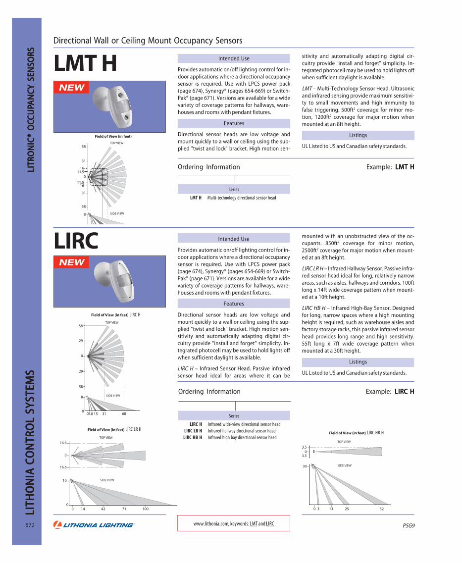
Directional Wall or Ceiling Mount Occupancy Sensors
LMT H Intended Use
Provides automatic on/off lighting control for in-door applications where a directional occupancysensor is required. Use with LPCS power pack(page 674), Synergy® (pages 654-669) or Switch-Pak® (page 671). Versions are available for a widevariety of coverage patterns for hallways, ware-houses and rooms with pendant fixtures.
Features
Directional sensor heads are low voltage andmount quickly to a wall or ceiling using the sup-plied "twist and lock" bracket. High motion sen-
sitivity and automatically adapting digital cir-cuitry provide "install and forget" simplicity. In-tegrated photocell may be used to hold lights offwhen sufficient daylight is available.
LMT – Multi-Technology Sensor Head. Ultrasonicand infrared sensing provide maximum sensitivi-ty to small movements and high immunity tofalse triggering. 500ft2 coverage for minor mo-tion, 1200ft2 coverage for major motion whenmounted at an 8ft height.
Listings
UL Listed to US and Canadian safety standards.
Ordering Information Example: LMT HLMT HLMT HLMT HLMT H
Series
LMT H Multi-technology directional sensor head
www.lithonia.com, keywords: LMT and LIRC
58
31
1611.5
31
58
8 SIDE VIEW
TOP VIEW
Field of View (in feet)
0
11.516
29
29
58
58
8
038 15 31 68
SIDE VIEW
TOP VIEW
Field of View (in feet)
0
0
0
30
3.5
3.5
52253 130
SIDE VIEW
TOP VIEW
Field of View (in feet)
LIRC Intended Use
Provides automatic on/off lighting control for in-door applications where a directional occupancysensor is required. Use with LPCS power pack(page 674), Synergy® (pages 654-669) or Switch-Pak® (page 671). Versions are available for a widevariety of coverage patterns for hallways, ware-houses and rooms with pendant fixtures.
Features
Directional sensor heads are low voltage andmount quickly to a wall or ceiling using the sup-plied "twist and lock" bracket. High motion sen-sitivity and automatically adapting digital cir-cuitry provide "install and forget" simplicity. In-tegrated photocell may be used to hold lights offwhen sufficient daylight is available.
LIRC H – Infrared Sensor Head. Passive infraredsensor head ideal for areas where it can be
mounted with an unobstructed view of the oc-cupants. 850ft2 coverage for minor motion,2500ft2 coverage for major motion when mount-ed at an 8ft height.
LIRC LR H – Infrared Hallway Sensor. Passive infra-red sensor head ideal for long, relatively narrowareas, such as aisles, hallways and corridors. 100ftlong x 14ft wide coverage pattern when mount-ed at a 10ft height.
LIRC HB H – Infrared High-Bay Sensor. Designedfor long, narrow spaces where a high mountingheight is required, such as warehouse aisles andfactory storage racks, this passive infrared sensorhead provides long range and high sensitivity.55ft long x 7ft wide coverage pattern whenmounted at a 30ft height.
Listings
UL Listed to US and Canadian safety standards.
Ordering Information Example: LIRC HLIRC HLIRC HLIRC HLIRC H
Series
LIRC H Infrared wide-view directional sensor headLIRC LR H Infrared hallway directional sensor head
LIRC HB H Infrared high bay directional sensor head
0
0
16.6
16.6
SIDE VIEW
TOP VIEW
Field of View (in feet)
14 42 71 100
10
0
LIRC H
LIRC LR HLIRC HB H

PSG9
LITHO
NIA
CON
TROL SYSTEM
SLITH
ON
IA CO
NTRO
L SYSTEMS
LITHO
NIA
CON
TROL SYSTEM
SLITH
ON
IA CO
NTRO
L SYSTEMS
LITHO
NIA
CON
TROL SYSTEM
S
673
LITRON
IC® OC
LITRON
IC® OC
LITRON
IC® OC
LITRON
IC® OC
LITRON
IC® OCCU
PCU
PCU
PCU
PCU
PAN
CA
NC
AN
CA
NC
AN
CY SENSO
RSY SEN
SORS
Y SENSO
RSY SEN
SORS
Y SENSO
RSOmni-directional Ceiling Mount Occupancy Sensors
Intended Use
Ceiling mount sensor heads provide automaticon/off lighting control for indoor applicationswhere an occupancy sensor with a 360° coveragepattern is required. Use with an LPCS power pack(page 674), Synergy® system (pages 654-669) orSwitchPak™ relay panel (page 671). Multi-tech-nology, ultrasonic and passive infrared sensors areavailable for a wide variety of applications.
Features
Omni-directional sensor heads are low voltageand mount quickly to a variety of ceiling surfacesusing the supplied hardware. High motion sensi-tivity and advanced, automatically adapting dig-
ital circuitry provide "install and forget" simplic-ity. Integrated photocell may be used to holdlights off when sufficient daylight is available.
LMTO H – Ultrasonic and infrared sensing pro-vide maximum sensitivity to small movementsand high immunity to false triggering. Perfect forclassrooms, large offices, conference rooms andcafeterias. 1000ft2 coverage for minor motion,2000ft2 coverage for major motion when mount-ed at an 8ft height.
LUSO H – Ultrasonic sensors provide excellentsensitivity to small movements without the re-quirement of an unobstructed view of the occu-pants. Use for storage areas, warehouses, cafeteri-as and public areas in commercial facilities.
Multi-Technology Sensor Head LMTO H
Ordering Information Example: LMTO HLMTO HLMTO HLMTO HLMTO H
Series
LMTO H Multi-technology ceiling-mounted sensorhead
Ordering Information: Example: LUSO HLUSO HLUSO HLUSO HLUSO H
Series
LUSO H Ultrasonic ceiling-mounted sensor head
Minor Motion, IR Major Motion, IR Minor Motion, Ultrasonic Major Motion, Ultrasonic
Ordering Information: Example: LIRO HLIRO HLIRO HLIRO HLIRO H
Series
LIRO H Infrared ceiling-mounted sensor head
www.lithonia.com, keywords: LMTO, LUSO and LIRO
0
16
16
11.5
11.5
0
0
20
10
10
20
SIDE VIEW
TOP VIEW
201515 11 119 95.65.6 3320
8
0
Ultrasonic Sensor Head LUSO H
Infrared Sensor Head LIRO H
1000ft2 coverage for minor motion, 2000ft2 cover-age for major motion when mounted at an 8ftheight.
LIRO H – Passive infrared sensor with a high im-munity to false triggering that works well inlobbies, closets, wide hallways and other areaswith an unobstructed view of the sensor.1500ft2 coverage for major motion whenmounted at an 8ft height.
Listings
UL Listed to US and Canadian safety standards.
0
20
8
16
16
11.5
11.5
20
SIDE VIEW
TOP VIEW
03 35.5 5.59 911 1115 1520 2032 3222.5 22.5
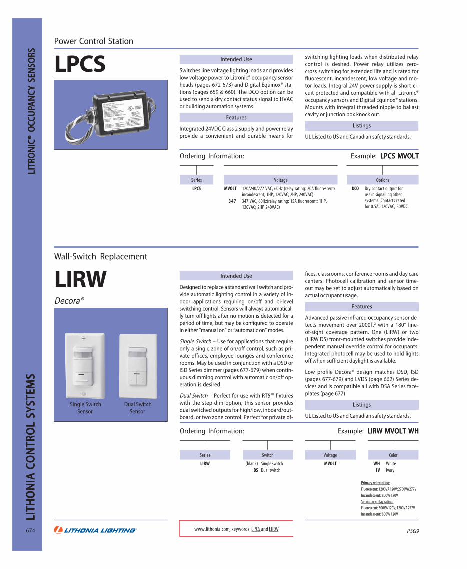
PSG9
LITH
ON
IA C
ON
TRO
L SY
STEM
SLI
THO
NIA
CO
NTR
OL
SYST
EMS
LITH
ON
IA C
ON
TRO
L SY
STEM
SLI
THO
NIA
CO
NTR
OL
SYST
EMS
LITH
ON
IA C
ON
TRO
L SY
STEM
S
674
LITR
ON
IC®
OC
LITR
ON
IC®
OC
LITR
ON
IC®
OC
LITR
ON
IC®
OC
LITR
ON
IC®
OC C
UP
CUP
CUP
CUP
CUP A
NC
AN
CA
NC
AN
CA
NC Y
SEN
SORS
Y SE
NSO
RSY
SEN
SORS
Y SE
NSO
RSY
SEN
SORS
Power Control Station
LPCS Intended Use
Switches line voltage lighting loads and provideslow voltage power to Litronic® occupancy sensorheads (pages 672-673) and Digital Equinox® sta-tions (pages 659 & 660). The DCO option can beused to send a dry contact status signal to HVACor building automation systems.
Features
Integrated 24VDC Class 2 supply and power relayprovide a convienient and durable means for
switching lighting loads when distributed relaycontrol is desired. Power relay utilizes zero-cross switching for extended life and is rated forfluorescent, incandescent, low voltage and mo-tor loads. Integral 24V power supply is short-ci-cuit protected and compatible with all Litronic®occupancy sensors and Digital Equinox® stations.Mounts with integral threaded nipple to ballastcavity or junction box knock out.
Listings
UL Listed to US and Canadian safety standards.
Wall-Switch Replacement
LIRWDecora®
Intended Use
Designed to replace a standard wall switch and pro-vide automatic lighting control in a variety of in-door applications requiring on/off and bi-levelswitching control. Sensors will always automatical-ly turn off lights after no motion is detected for aperiod of time, but may be configured to operatein either “manual on” or “automatic on” modes.
Single Switch – Use for applications that requireonly a single zone of on/off control, such as pri-vate offices, employee lounges and conferencerooms. May be used in conjunction with a DSD orISD Series dimmer (pages 677-679) when contin-uous dimming control with automatic on/off op-eration is desired.
Dual Switch – Perfect for use with RT5™ fixtureswith the step-dim option, this sensor providesdual switched outputs for high/low, inboard/out-board, or two zone control. Perfect for private of-
fices, classrooms, conference rooms and day carecenters. Photocell calibration and sensor time-out may be set to adjust automatically based onactual occupant usage.
Features
Advanced passive infrared occupancy sensor de-tects movement over 2000ft2 with a 180° line-of-sight coverage pattern. One (LIRW) or two(LIRW DS) front-mounted switches provide inde-pendent manual override control for occupants.Integrated photocell may be used to hold lightsoff when sufficient daylight is available.
Low profile Decora® design matches DSD, ISD(pages 677-679) and LVDS (page 662) Series de-vices and is compatible all with DSA Series face-plates (page 677).
Listings
UL Listed to US and Canadian safety standards.
Ordering Information: Example: LIRW MVOLT WHLIRW MVOLT WHLIRW MVOLT WHLIRW MVOLT WHLIRW MVOLT WH
Series
LIRW
Single SwitchSensor
Dual SwitchSensor
Primary relay rating:
Fluorescent: 1200VA 120V; 2700VA 277V
Incandescent: 800W 120VSecondary relay rating:
Fluorescent: 800VA 120V; 1200VA 277V
Incandescent: 800W 120V
Series
LPCS
Voltage
MVOLT 120/240/277 VAC, 60Hz (relay rating: 20A fluorescent/incandescent; 1HP, 120VAC; 2HP, 240VAC)
347 347 VAC, 60Hz(relay rating: 15A fluorescent; 1HP,120VAC; 2HP 240VAC)
Options
DCO Dry contact output foruse in signalling othersystems. Contacts ratedfor 0.5A, 120VAC, 30VDC.
Color
WH WhiteIV Ivory
Voltage
MVOLT
Switch
(blank) Single switchDS Dual switch
www.lithonia.com, keywords: LPCS and LIRW
Ordering Information: Example: LPCS MVOLTLPCS MVOLTLPCS MVOLTLPCS MVOLTLPCS MVOLT

PSG9
LITHO
NIA
CON
TROL SYSTEM
SLITH
ON
IA CO
NTRO
L SYSTEMS
LITHO
NIA
CON
TROL SYSTEM
SLITH
ON
IA CO
NTRO
L SYSTEMS
LITHO
NIA
CON
TROL SYSTEM
S
675
Capacity (VA)
2000 2000 watts
Series
SQIDC
Number of presets and channels
6P 4C 6 presets, 4 channels6P 8C 6 presets, 8 channels1
Wallplate style
SD SolidTR Translucent
Voltage
120
Ordering Information Example: SQIDC 2000 6P 4C BJ4 TR 120SQIDC 2000 6P 4C BJ4 TR 120SQIDC 2000 6P 4C BJ4 TR 120SQIDC 2000 6P 4C BJ4 TR 120SQIDC 2000 6P 4C BJ4 TR 120
Series Width Thickness Height
SQIDC 10-1/8 (257) 1/4 (6) 4-5/8 (117)Accessories (Order separately)
SQCS 5GB 5-gang backbox for 4C and 8C stations.BKLE Engraved button caps. Specify wording.
NOTES:
1 8-channel unit requires Sequel® MiniPac® dimmer cabinet (page 676) forcontrol of loads on channels 5-8.
2 Additional delivery time and/or cost may be associated.
Series
SQRS
Ordering Information Example: SQRS2S BJ4SQRS2S BJ4SQRS2S BJ4SQRS2S BJ4SQRS2S BJ4
Accessories (Order separately)
SYRS 1GR 1-gang plaster ring.BKLE Engraved button caps. Specify wording.
Series Width Thickness Height WeightSQRS 2-7/8 (73) 1/4 (6) 4-5/8 (117) 1/2 (.2)
Integrated Wallbox Dimming System
SQIDCSequel® IDC
Intended Use
Provides manual and preset dimming of mostlamp types in wallbox applications. Offered in avariety of styles and architectural finishes. Maybe used singly, with matching remote stations orinterfaced with external systems.
Features
Master raise and lower buttons adjust intensity ofall lights dimmed from station. Channel raise andlower buttons adjust intensity level of individualchannels. LED bar graph displays intensity level.Select button saves presets. Fade time is adjust-able for each preset scene. Preset button savesand activates presets. Off function turns off alllighting. Low-end and high-end dimming limits
Intended Use
Activates control functions in conjunction withthe Sequel® IDC wallbox dimming system.
Features
Operation – Functions include preset recall,channel raise/lower, master raise/lower and off.
Installation – Mounts to a Lithonia SYRS 1GR boxor 2" wide single-gang switch box.
Classification – Class 2 low voltage device.
DIM
MIN
GD
IMM
ING
DIM
MIN
GD
IMM
ING
DIM
MIN
G
and dimmer curves are adjustable per channel.
Terminals on rear of station allow access fromSQRS remote stations or momentary dry contactclosures to: six presets, master raise/lower, chan-nel raise/lower, select and off.
Overall maximum is 2000VA. Maximum per out-put (1-4) is 600VA electronic ballast or 800VAincandescent, magnetic low voltage and mag-netic ballast, 600VA electronic two- and three-wire fluorescent ballasts. Mounts in five-gangmasonry wall box.
Listings
UL Listed to US and Canadian safety standards.
Dimensions are shown in inches (millimeters) unless otherwise noted.
Remote Stations
SQRS
Dimensions are shown in inches (millimeters) or pounds (kilograms) unlessotherwise noted.
Number of buttons
1S 1 button2S 2 buttons3S 3 buttons4S 4 buttons5S 5 buttons6S 6 buttons9S 9 buttons
www.lithonia.com, keywords: SQIDC and SQRS
Finish
BJ4 Brushed stainless steel, black buttonsWC2 Painted white, white buttons
IE3 Painted ivory, ivory buttonsBL4 Painted black, black buttons2
BF4 Polished brass, black buttons2
Finish
BJ4 Brushed stainless steel, black buttonsWC2 Painted white, white buttons
IE3 Painted ivory, ivory buttonsBL4 Painted black, black buttons1
BF4 Polished brass, black buttons1
NOTES:
1 Additional delivery time and/or cost may be associated.

PSG9
LITH
ON
IA C
ON
TRO
L SY
STEM
SLI
THO
NIA
CO
NTR
OL
SYST
EMS
LITH
ON
IA C
ON
TRO
L SY
STEM
SLI
THO
NIA
CO
NTR
OL
SYST
EMS
LITH
ON
IA C
ON
TRO
L SY
STEM
S
676
Ordering Information Example: SQMPDC 4UX2 S2 120SQMPDC 4UX2 S2 120SQMPDC 4UX2 S2 120SQMPDC 4UX2 S2 120SQMPDC 4UX2 S2 120
www.lithonia.com, keywords: SQMPDC and RDM
Remote High Power Dimmer Pack
SQMPDCMiniPac®
Remote Dimmer Modules
RDM
Intended Use
Increases the individual channel capacity forSQIDC wall box dimming system (page 675) ormay be used as a remote dimmer pack for aSynergy® system equipped with the Legacyoption (page 665).
Features
When used with SQIDC: An integral switch matrixallows dimmers to be flexibly assigned to SQIDCstation channels. Up to four dimmer pack may beused per SQIDC system.
When used with Synergy®: MLX controller withLegacy option required; up to 64 dimmer packsmay be connected to each controller. Dimmersare fully configurable from system controller andsoftware and may be controlled by any Synergy®
Intended Use
Used to boost the capacity of an ISD (page 678),DSD (page 677), or SQIDC (page 675) Series wall-box dimmer. Also allows an ISD Series dimmer tocontrol three-wire fluorescent dimming ballastsand SQIDC dimmers to control four-wire fluores-cent dimming ballasts.
Features
Available for a wide variety of dimming load
Ordering Information Example: RDMI 2000 120RDMI 2000 120RDMI 2000 120RDMI 2000 120RDMI 2000 120
Series
SQMPDC
Options
EM For essential lighting loads. Alldimmers automatically set to full onupon loss of normal power. Type4UX2 or 4UX4 cabinets only. Transferof input fee by others.
Number of dimmers
2 2 dimmers4 4 dimmers
Dimmer type
UX Universal incandesent; two wirefluorescent
UF Universal incandesent; and two,three and four-wire fluores-cent; non-dim
Capacity per dimmer
2 2000VA, 120V4 4000VA, 277V
Voltage
120 120V (single phase)277 277V (single phase)
Type
S2
DIM
MIN
GD
IMM
ING
DIM
MIN
GD
IMM
ING
DIM
MIN
G
user interface or schedule.
High quality architectural-grade filters mini-mize lamp noise. Dimmers are cooled throughnatural convection flow provided by front coverventing and are available with or without posi-tive air gap on/off relays.
Installation – NEMA 1 enclosure is suitable forsurface or flush wall mounting. Dimmers are fedfrom individual 15A or 20A branch circuits. Alldimmers in a single pack must be fed from a sin-gle phase; no phase relationship between differ-ent dimmer packs or SQIDC circuits. Connects toSynergy® cabinet or SQIDC via Lithonia SYA CA-BLES2 network wire (page 670).
Listings
UL Listed to US and Canadian safety standards.
types. Models for use with line voltage loads in-clude an integral RFI filter and may be surface orflush mounted using a 1900 box and 2-gangraised cover. All models are phase independentof the control device and equipped with a low-end trim adjustment.
Listings
UL Listed. CSA Certified. NOM Certified.
Series
RDMI 2000 120 1920 W/VA, 120V, 50/60Hz for incandescent, magnetic low voltage, neon and cold-cathode.RDMF 2000 120 1920 VA, 120V, 50/60Hz for Advance Mark 10™ and Lutron Hi-Lume®, Tu-Wire® and ECO10™ fluorescentRDMI 3000 277 3000 VA, 277V, 50/60Hz for Advance Mark 10™ and Lutron Hi-Lume®, Tu-Wire® and ECO10™ fluorescent
RDMBC 120/277 1920VA at 120V, 4400VA at 277V, 50/60Hz for 0-10VDC fluorescent ballasts only. Mounts to a grounded 4" outlet box.
Load type Load voltage Controller RDMIncandescent, magnetic low voltage, neon 120V SQIDC or ISD 600 I 120 RDMI 2000 120Advance Mark 10™, Lutron Tu-Wire® 120V SQIDC, ISD 600 ADEZ 120, RDMF 2000 120Advance Mark 10™, Lutron Tu-Wire® 277V or DSD 500 ADEZ 120 RDMF 3000 277Lutron Hi-Lume®/ECO10™ 120V
SQIDC or ISD 600 I 120RDMF 2000 120
Lutron Hi-Lume®/ECO10™ 277V RDMF 3000 2770-10VDC Fluorescent 120V or 277V SQIDC or ISD 600 I 120 RDMBC 120/277

PSG9
LITHO
NIA
CON
TROL SYSTEM
SLITH
ON
IA CO
NTRO
L SYSTEMS
LITHO
NIA
CON
TROL SYSTEM
SLITH
ON
IA CO
NTRO
L SYSTEMS
LITHO
NIA
CON
TROL SYSTEM
S
677
Shown with DSA FP D1 wallplate.
Architectural Wallbox Dimmers
DSDIntended Use
DSD Series dimmers provide smooth full-rangedimming of fluorescent fixtures equipped withthe Advance Mark 10™ dimming ballast. Dim-mers have a strap-mount design and may be usedindividually or ganged together for multipleload applications. These dimmers are ideally suit-ed for use with Lithonia fixtures with the ADEZdimming ballast option.
Features
Operation – Linear slide dimming with separaterocker switch for preset or three-way on/off op-
eration and single location dimming.
Installation – All dimmers mount in standard sin-gle-gang switch box and can be ganged togeth-er using multi-gang wallplates (see below).
Compatability – Two-wire dimming ballasts as in-dicated on page 680.
Listings
UL Listed. CSA Certified. NOM Certified.
Capacity (VA)
500 500 VA
Series
DSD
Ballast type
ADEZ Advance Mark 10™ fluorescent
Ordering Information Example: DSD 500 ADEZ 277 IVDSD 500 ADEZ 277 IVDSD 500 ADEZ 277 IVDSD 500 ADEZ 277 IVDSD 500 ADEZ 277 IV
Voltage
120277
Color
IV Ivory1
WH White1
Advance Mark 10TM two-wire ballasts, 120V and 277V
1/4(6)
4-1/2(114)
2-11/16(68)
2-5/8(67)
1(28)
NOTES:
1 Includes standard Leviton Decora® wallplate. Order screwless or multi-gangDSA wallplates separately below.
Capacities and Derating
Advance Max. no. ballast/dimmerMark 10™ Lamp One-gang orcatalog no. type multi-gangVEZ-2Q26 CFM26W 8
VEZ-1T32 CFM32W 12
VEZ-1T42 CFM42W 10
VEZ-1Q18 CFQ18W 22
VEZ-2Q18 CFQ18W 11
VEZ-132 F32T8 13
VEZ-2S32 F32T8 6
VEZ-3S32 F3T8 4
VEZ-154 F54T5/HO 7
VEZ-2S54 F54T5/HO 4
VEZ-1TTS40 FT40W 12
VEZ-2TTS40 FT40W 6
277V277V277V277V277V
Advance Max. no. ballast/dimmerMark 10™ Lamp One- Multi-catalog no. type gang gangREZ-1T32 CFM32W 13 10
REZ-1T42 CFM42W 10 8
REZ-1Q18 CFQ18W 23 18
REZ-2Q18 CFQ18W 11 9
REZ-2Q26 CFQ26W 8 6
REZ-2T42 CFTR42W 5 4
REZ-132 F32T8 13 11
REZ-2S32 F32T8 6 5
REZ-3S32 F32T8 4 3
REZ-154 F54T5/HO 7 6
REZ-2S54 F54T5/HO 3 3
REZ-1TTS40 FT40W 12 9
REZ-2TTS40 FT40W 6 4
120V120V120V120V120V
For higher capacity, use either ISD ADEZ (page 678) or DSD with RDM remote dimmer (page 676).Dimensions are shown in inches (millimeters) unless otherwise noted.
Architectural Wallplates for Decora® Products
DSA FPIntended Use
Provides an architecturally-styled finish treat-ment for DSD, ISD, LVDS and LIRW Series prod-ucts. Wallplates are available for individual de-vices and multi-gang applications with up tosix devices.
D1 One openingD2 Two openings
Color
Ordering Information Example: DSA FP D1 WHDSA FP D1 WHDSA FP D1 WHDSA FP D1 WHDSA FP D1 WH
D5 Five openingsD6 Six openings
Openings2
www.lithonia.com, keywords: DSD and DSA FP
WH WhiteIV IvoryAL Almond3
NOTES:
1 Some color and opening combinations only are available with visible mounting screws.2 One gang per opening is required.
3 Additional delivery time and/or cost may be associated with these premium colors.
Features
Low profile wallplates are compatible with DSD,ISD, LVDS and LIRW Series products and otherDecora® style devices.
Adapter strap permits mounting to the devicewithout exposed fasteners1.
GY Gray3
BK Black3
BR Brown3
DIM
MIN
GD
IMM
ING
DIM
MIN
GD
IMM
ING
DIM
MIN
G
Series
DSA FP D3 Three openingsD4 Four openings

PSG9
LITH
ON
IA C
ON
TRO
L SY
STEM
SLI
THO
NIA
CO
NTR
OL
SYST
EMS
LITH
ON
IA C
ON
TRO
L SY
STEM
SLI
THO
NIA
CO
NTR
OL
SYST
EMS
LITH
ON
IA C
ON
TRO
L SY
STEM
S
678
DIM
MIN
GD
IMM
ING
DIM
MIN
GD
IMM
ING
DIM
MIN
GArchitectural Wallbox Dimmers
ISD Intended Use
The ISD Series wallbox dimmers are designed toprovide smooth full-range dimming for a vari-ety of loads. Products are available for incandes-cent, low voltage, electronic low voltage andfluorescent two-wire and four-wire load types.The ISD dimmers can be used in place of a stan-dard wall switch to provide on/off and dimminglighting control.
Features
Fluid slide movement allows fine adjustment oflight level over the entire dimming range. Sepa-rate on/off switch permits switching of lightingat a preset level. An integral LED indicator on il-luminated dimmers turns on when the switch is
Ordering Information Example: ISD 600 LV 120 WH/IVISD 600 LV 120 WH/IVISD 600 LV 120 WH/IVISD 600 LV 120 WH/IVISD 600 LV 120 WH/IV
Catalog number
Incandescent (supplied with white and ivory faceplates)ISD 600 I 120 WH/IV Illuminated slide dimmer; 600W,
120V, 60HzISD 1000 I 120 WH/IV Illuminated slide dimmer; 1000W,
120V, 60HzMagnetic low voltage (supplied with white and ivory faceplates)
ISD 600 LV 120 WH/IV Illuminated slide dimmer; 600VA,120V, 60Hz
ISD 1000 LV 120 WH/IV Illuminated slide dimmer; 1000VA,120V, 60Hz
Electronic low voltage (supplied with white and ivory faceplates)ISD 400 ELV 120 WH/IV Illuminated slide dimmer; 400VA,
120V, 60HzFluorescent Mark 10™ (supplied with white and ivory faceplates)
ISD 600 ADEZ 120 WH/IV Slide dimmer; 600VA, 120V, 60HzISD 1000 ADEZ 120 WH/IV Slide dimmer; 1000VA, 120V, 60HzISD 1200 ADEZ 277 WH/IV Slide dimmer; 1200VA, 277V, 60HzFluorescent four-wire (supplied with white and ivory faceplates)
ISD BC 120/277 WH/IV Ballast controller; 120/277V
www.lithonia.com, keyword: ISD
Accessories (Order separately)
ISD CCKIT__ Color change kit, specify WH (White), IV (Ivory),GY (Gray), BR (Brown), BK (Black) or AL (Al-mond).
DSA FP D__ Low profile thermoplastic wall-plate for ISD orLeviton Decora® compatible devices (page 677).
0.38 (9.7 )
3.28 (83.3)
4.15(105.4 )
2.12 (53.8)
1.41 (35.8 )
2.68 (68.1 )
off to facilitate switch location in a dark room.Can be used with standard three-way or four-wayswitch for multi-location switching. ISD Seriesdimmers are compatible with Leviton Decora®Series wallplates. Single location, linear slidedimming with separate push on/off switch forpreset three-way and four-way switching. Avail-able in standard white and ivory and suppliedwith a matching single-gang Decora® style wall-plate. Snap-on Decora® style wallplate colorchange kits available (gray, black, brown, almond,white and ivory). Devices can be multi-gangmounted (optional multi-gang DSA wallplate re-quired – see page 677).
Listings
UL Listed. CSA Certified. NOM Certified.
Maximum number of ballasts/dimmer
120V Advance Mark 10™
ISD 600 ADEZ 120 ISD 1000 ADEZ 120
Lamp One Two More than One Two More thanCatalog Number type gang gang two gang gang gang two gangREZ-1T32 CFM32W 15 13 10 26 20 18
REZ-1T42 CFM42W 12 10 8 20 16 14
REZ-1Q18 CFQ18W 27 23 18 46 37 32
REZ-2Q18 CFQ18W 13 11 9 23 18 16
REZ-2Q26 CFQ26W 10 8 6 17 13 12
REZ-2T42 CFTR42W 6 5 4 10 8 7
REZ-132 F32T8 16 13 11 27 22 19
REZ-2S32 F32T8 8 6 5 13 11 9
REZ-3S32 F32T8 5 4 3 9 7 6
REZ-154 F54T5/HO 9 7 6 15 12 11
REZ-2S54 F54T5/HO 4 3 3 7 6 5
REZ-1TTS40 FT40W 14 12 9 24 19 17
REZ-2TTS40 FT40W 7 6 4 12 9 8
Maximum load/dimmer
ISD I/ISD LV/ISD ELV
One Two More thanCatalog Number gang gang two gangISD 1000 I 120 1000W 800W 700W
ISD 600 I 120 600W 500W 400W
ISD 1000 LV 120 1000VA 800VA 700VA
ISD 600 LV 120 600VA 500VA 400VA
ISD 400 ELV 120 400VA 350VA 250VA
Maximum number of ballasts/dimmer
277V Advance Mark 10™
ISD 1200 ADEZ 277
Lamp One Two More thanCatalog Number type gang gang two gangVEZ-2Q26 CFM26W 20 20 20
VEZ-1T32 CFM32W 30 30 30
VEZ-1T42 CFM42W 24 24 24
VEZ-1Q18 CFQ18W 54 54 54
VEZ-2Q18 CFQ18W 27 27 27
VEZ-2T42 CFTR42W 12 12 12
VEZ-132 F32T8 33 33 33
VEZ-2S32 F32T8 16 16 16
VEZ-3S32 F32T8 11 11 11
VEZ-154 F54T5/HO 18 18 18
VEZ-2S54 F54T5/HO 9 9 9
VEZ-1TTS40 FT40W 28 28 28
VEZ-2TTS40 FT40W 14 14 14

PSG9
LITHO
NIA
CON
TROL SYSTEM
SLITH
ON
IA CO
NTRO
L SYSTEMS
LITHO
NIA
CON
TROL SYSTEM
SLITH
ON
IA CO
NTRO
L SYSTEMS
LITHO
NIA
CON
TROL SYSTEM
S
679
DIM
MIN
GD
IMM
ING
DIM
MIN
GD
IMM
ING
DIM
MIN
GDimming Photosensor for Four-Wire Ballasts
ISD DPCIntended Use
Connects directly to up to 80 compatible four-wire dimming ballasts with Class 2 low voltagecontrol wire. Photocell automatically maintainsa constant preset lighting level.
Features
Operation – Automatically maintains a constantpreset lighting level in response to the availabili-ty of natural daylight (daylighting) and/or auto-matically maintains a constant preset light levelover the life of the lighting system (lumen depre-ciation maintenance). 7-140 footcandles responserange ± 1% at 70°F. Immediate or extended fadetime response to light level changes.
Series
ISD DPC Dimming photocell
Ordering Information Example: ISD DPC ISD DPC ISD DPC ISD DPC ISD DPC
Applications:Install near fixtures being controlled or central to circuit being controlled. Cone ofresponse of photocell (60°) must contain area that is lit by fixtures being controlled.Cone of response area must not contain any artificial uplight (i.e., desk lamp).
For day light harvesting, photocell should be installed six to eight feet from windowline, depending on ceiling height, so that cone of response only contains work areainside actual window line. Can be used with an ISD BC ballast controller for auto-matic and manual dimming control.
1.28"
1.15"
www.lithonia.com, keyword: ISD DPC
Housing – Low-profile, UV-stable, white ABShousing with flat Fresnel lens.
Installation – Mounts directly to the ceiling tile.Class 2 low voltage control wire.
Compatability – Four-wire dimming ballasts asindicated on page 680.
Classification – Class 2 low voltage device.
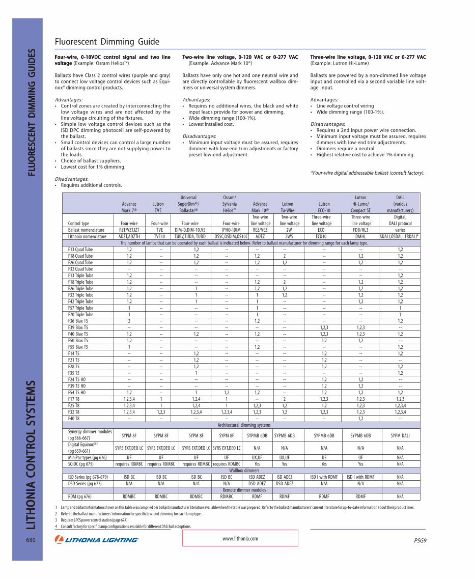
PSG9
LITH
ON
IA C
ON
TRO
L SY
STEM
SLI
THO
NIA
CO
NTR
OL
SYST
EMS
LITH
ON
IA C
ON
TRO
L SY
STEM
SLI
THO
NIA
CO
NTR
OL
SYST
EMS
LITH
ON
IA C
ON
TRO
L SY
STEM
S
680
FLFLFLFL FLU
ORE
SCEN
T D
IMM
ING
GU
IDES
UO
RESC
ENT
DIM
MIN
G G
UID
ESU
ORE
SCEN
T D
IMM
ING
GU
IDES
UO
RESC
ENT
DIM
MIN
G G
UID
ESU
ORE
SCEN
T D
IMM
ING
GU
IDES
Fluorescent Dimming Guide
Four-wire, 0-10VDC control signal and two lineFour-wire, 0-10VDC control signal and two lineFour-wire, 0-10VDC control signal and two lineFour-wire, 0-10VDC control signal and two lineFour-wire, 0-10VDC control signal and two linevoltage voltage voltage voltage voltage (Example: Osram Helios™)
Ballasts have Class 2 control wires (purple and gray)to connect low voltage control devices such as Equi-nox® dimming control products.
Advantages:• Control zones are created by interconnecting the
low voltage wires and are not affected by theline voltage circuiting of the fixtures.
• Simple low voltage control devices such as theISD DPC dimming photocell are self-powered bythe ballast.
• Small control devices can control a large numberof ballasts since they are not supplying power tothe loads.
• Choice of ballast suppliers.• Lowest cost for 1% dimming.
Disadvantages:• Requires additional controls.
Two-wire line voltage, 0-120 VAC or 0-277 VACTwo-wire line voltage, 0-120 VAC or 0-277 VACTwo-wire line voltage, 0-120 VAC or 0-277 VACTwo-wire line voltage, 0-120 VAC or 0-277 VACTwo-wire line voltage, 0-120 VAC or 0-277 VAC(Example: Advance Mark 10®)
Ballasts have only one hot and one neutral wire andare directly controllable by fluorescent wallbox dim-mers or universal system dimmers.
Advantages:• Requires no additional wires, the black and white
input leads provide for power and dimming.• Wide dimming range (100-1%).• Lowest installed cost.
Disadvantages:• Minimum input voltage must be assured, requires
dimmers with low-end trim adjustments or factorypreset low-end adjustment.
Universal Osram/ Lutron DALIAdvance Lutron SuperDim®/ Sylvania Advance Lutron Lutron Hi-Lume/ (variousMark 7® TVE Ballastar® Helios™ Mark 10® Tu-Wire ECO-10 Compact SE manufacturers)
Two-wire Two-wire Three-wire Three-wire Digital,Control type Four-wire Four-wire Four-wire Four-wire line voltage line voltage line voltage line voltage DALI protocolBallast nomenclature RZT/VZT,IZT TVE DIM-D,DIM-10,V5 (PHO-)DIM REZ/VEZ 2W ECO FDB/HL3 variesLithonia nomenclature ADZT,ADZTH TVE10 TUBV,TUDA, TUDD OS5C,OSDIM,OS10C ADEZ 2W5 ECO10 DMHL ADALI,OSDALI,TRDALI4
The number of lamps that can be operated by each ballast is indicated below. Refer to ballast manufacturer for dimming range for each lamp type.F13 Quad Tube 1,2 -- 1,2 -- -- -- -- -- 1,2F18 Quad Tube 1,2 -- 1,2 -- 1,2 2 -- 1,2 1,2F26 Quad Tube 1,2 -- 1,2 -- 1,2 1,2 -- 1,2 1,2F32 Quad Tube -- -- -- -- -- -- -- -- --F13 Triple Tube 1,2 -- -- -- -- -- -- -- 1,2F18 Triple Tube 1,2 -- -- -- 1,2 2 -- 1,2 1,2F26 Triple Tube 1,2 -- 1 -- 1,2 1,2 -- 1,2 1,2F32 Triple Tube 1,2 -- 1 -- 1 1,2 -- 1,2 1,2F42 Triple Tube 1,2 -- 1 -- 1 -- -- 1,2 1,2F57 Triple Tube 1 -- -- -- 1 -- -- -- 1F70 Triple Tube 1 -- -- -- 1 -- -- -- 1F36 Biax T5 2 -- -- -- 1,2 -- -- -- 1.2F39 Biax T5 -- -- -- -- -- -- 1,2,3 1,2,3 --F40 Biax T5 1,2 -- 1,2 -- 1,2 -- 1,2,3 1,2,3 1,2F50 Biax T5 1,2 -- -- -- -- -- 1,2 1,2 --F55 Biax T5 1 -- -- -- 1,2 -- -- -- 1,2F14 T5 -- -- 1,2 -- -- -- 1,2 -- 1,2F21 T5 -- -- 1,2 -- -- -- 1,2 -- --F28 T5 -- -- 1,2 -- -- -- 1,2 -- 1,2F35 T5 -- -- 1 -- -- -- -- -- 1,2F24 T5 HO -- -- -- -- -- -- 1,2 1,2 --F39 T5 HO -- -- -- -- -- -- 1,2 1,2 --F54 T5 HO 1,2 -- 1 1,2 1,2 -- 1,2 1,2 1,2F17 T8 1,2,3,4 1 1,2,4 1 -- 2 1,2,3 1,2,3 1,2,3F25 T8 1,2,3,4 1 1,2,4 1 1,2,3 1,2 1,2 1,2,3 1,2,3,4F32 T8 1,2,3,4 1,2,3 1,2,3,4 1,2,3,4 1,2,3 1,2 1,2,3 1,2,3 1,2,3,4F40 T8 -- -- -- -- -- -- -- 1,2 --
Architectural dimming systemsSynergy dimmer modules(pg 666-667) SYPM 8F SYPM 8F SYPM 8F SYPM 8F SYPMB 6DB SYPMB 6DB SYPMB 6DB SYPMB 6DB SYPM DALI
Digital Equinox®3
SYRS EXT,DEQ LC SYRS EXT,DEQ LC SYRS EXT,DEQ LC SYRS EXT,DEQ LC N/A N/A N/A N/A N/A(pg 659-661)MiniPac types (pg 676) UF UF UF UF UX,UF UX,UF UF UF N/ASQIDC (pg 675) requires RDMBC requires RDMBC requires RDMBC requires RDMBC Yes Yes Yes Yes N/A
Wallbox dimmersISD Series (pg 678-679) ISD BC ISD BC ISD BC ISD BC ISD ADEZ ISD ADEZ ISD I with RDMF ISD I with RDMF N/ADSD Series (pg 677) N/A N/A N/A N/A DSD ADEZ DSD ADEZ N/A N/A N/A
Remote dimmer modulesRDM (pg 676) RDMBC RDMBC RDMBC RDMBC RDMF RDMF RDMF RDMF N/A
Three-wire line voltage, 0-120 VAC or 0-277 VACThree-wire line voltage, 0-120 VAC or 0-277 VACThree-wire line voltage, 0-120 VAC or 0-277 VACThree-wire line voltage, 0-120 VAC or 0-277 VACThree-wire line voltage, 0-120 VAC or 0-277 VAC(Example: Lutron Hi-Lume)
Ballasts are powered by a non-dimmed line voltageinput and controlled via a second variable line volt-age input.
Advantages:• Line voltage control wiring• Wide dimming range (100-1%).
Disadvantages:• Requires a 2nd input power wire connection.• Minimum input voltage must be assured, requires
dimmers with low-end trim adjustments.• Dimmers require a neutral.• Highest relative cost to achieve 1% dimming.
*Four-wire digital addressable ballast (consult factory).
www.lithonia.com
1 Lamp and ballast information shown on this table was compiled per ballast manufacturer literature available when the table was prepared. Refer to the ballast manufacturers’ current literature for up-to-date information about their product lines.
2 Refer to the ballast manufacturers’ information for specific low-end dimming for each lamp type.
3 Requires LPCS power control station (page 674).4 Consult factory for specific lamp configurations available for different DALI ballast options.

PSG9
LITHO
NIA
CON
TROL SYSTEM
SLITH
ON
IA CO
NTRO
L SYSTEMS
LITHO
NIA
CON
TROL SYSTEM
SLITH
ON
IA CO
NTRO
L SYSTEMS
LITHO
NIA
CON
TROL SYSTEM
S
681
FLFL FLFLFLUO
RESCENT D
IMM
ING
UO
RESCENT D
IMM
ING
UO
RESCENT D
IMM
ING
UO
RESCENT D
IMM
ING
UO
RESCENT D
IMM
INGCAP
OFF
LINEVOLTAGE
NEUTRAL
HOT
GREEN
TWO-WIRE LINE VOLTAGE DIMMING BALLAST EXAMPLE FOR SINGLE LOCATION CONTROL
TWO-WIRE LINE VOLTAGE DIMMING BALLAST EXAMPLEFOR TWO LOCATION CONTROL
FLUORESCENTFIXTURES WITH
TWO-WIREDIMMING BALLASTS
BLACK
ISD ADEZ ORDSD ADEZ
DIMMER
120V THREE-WIRE LINE VOLTAGE DIMMING BALLAST EXAMPLEFOR SINGLE LOCATION CONTROL
BLA
CK
ORA
NG
E
WHITE
LOAD
SWITCHED HOT
FLUORESCENTFIXTURES WITH
THREE-WIREDIMMING BALLASTS
RDM MAY ALTERNATELY BE POWERED BY A SEPARATE 120V CIRCUIT
RDMF 2000 120REMOTEDIMMERMODULE
HOT
NEUTRAL
ISD 600 I 120DIMMER
BLACK
GREEN
RED
RED
CAPOFF
SWITCHED HOT
NEUTRAL
ISD 600 I 120DIMMER
BLACK
GREEN
RED
RED
CAPOFF
RDMF 3000 277REMOTEDIMMERMODULE
120V HOT
LOAD
120V LINE VOLTAGEFOR CONTROL SIGNAL
277V LINE VOLTAGETO POWER FIXTURES
277V HOT
NEUTRAL
FLUORESCENTFIXTURES WITH
THREE-WIREDIMMING BALLASTS
ORANGE
BLACK
WH
ITE
277V THREE-WIRE LINE VOLTAGE DIMMING BALLAST EXAMPLEFOR SINGLE LOCATION CONTROL
CAPOFF
LINEVOLTAGE
LINEVOLTAGE
LINEVOLTAGE
NEUTRAL
HOT
GREEN
NEUTRAL
GREEN
FOUR-WIRE 0-10V DIMMING BALLAST EXAMPLEFOR TWO LOCATION CONTROL
ISD BCDIMMER
GREEN
GRAY
BLACK
PURPLEFLUORESCENT
FIXTURES WITHFOUR-WIRE
DIMMING BALLASTS
CLASS 2CONDUCTORS
FOUR-WIRE O-10V DIMMING BALLAST EXAMPLEFOR SINGLE LOCATION CONTROL
REDBLACK
FLUORESCENTFIXTURES WITH
FOUR-WIREDIMMING BALLASTS
HOTRED
TYPICAL WIRING DIAGRAMSFOR FLUORESCENT WALLBOX DIMMERS
TWO-WIRE DIMMING BALLASTS (ADVANCE MARK 10®, LUTRON TU-WIRE)120V OR 277V
FOUR-WIRE DIMMING BALLASTS (ADVANCE MARK 7®, SYLVANIA HELIOS™)
120V OR 277V
THREE-WIRE DIMMING BALLASTS (LUTRON HILUME, ECO-10)
ISD BCDIMMER
REDGRAY
PURPLE
CLASS 2CONDUCTORS
ISD ADEZ ORDSD ADEZDIMMER
RED
RED
GREEN
BLACKFLUORESCENT
FIXTURES WITHTWO-WIRE
DIMMING BALLASTS
NEUTRAL
3 WAYSWITCH
RED
LINEVOLTAGE
HOTRED
GREEN
RED
3 WAYSWITCH
Fluorescent Wiring Guide
www.lithonia.com