control system list of experiments
TRANSCRIPT

!"#$!%&'('#)*&%+,&-))./01.23&
%+,&*+"4+%&-&56&')*&) )3& 789:&0&
CONTROL SYSTEM
LIST OF EXPERIMENTS S.
NO
NAME OF THE EXPERIMENT PAGE
NO.
1. (A) TO STUDY A.C SERVO MOTOR AND PLOT ITS TORQUE SPEED
CHARACTERISTICS.
(B) TO STUDY D.C SERVO MOTOR AND PLOT ITS TORQUE SPEED
CHARACTERISTICS.
3
2. TO STUDY A STEPPER MOTOR & EXECUTE MICROPROCESSOR OR
COMPUTER BASED CONTROL OF THE SAME BY CHANGING NUMBER OF
STEPS, DIRECTION OF ROTATION & SPEED.
11
3. TO STUDY THE MAGNETIC AMPLIFIER AND PLOT ITS LOAD CURRENT V/S
CONTROL CURRENT CHARACTERISTIC FOR SERIES AND PARALLEL
MODE.
15
4. TO PLOT THE LOAD CURRENT V/S CONTROL CURRENT
CHARACTERISTICS FOR SELF EXCITED MODE OF THE MAGNETIC
AMPLIFIER.
18
5. (A) TO STUDY THE SYNCHRO TRANSMITTER IN TERMS OF POSITION V/S
PHASE AND VOLTAGE MAGNITUDE WITH RESPECT TO ROTOR VOLTAGE
MAGNITUDE/PHASE
(B) TO STUDY OF REMOTE POSITION INDICATION SYSTEM USING
SYNCHRO TRANSMITTER /RECEIVER.
21
6. TO STUDY CHARACTERISTICS OF POSITIONAL ERROR DECTECTOR BY
ANGULAR DISPLACEMENT OF TWO SERVO POTENTIOMETERS. . 24
7. TO STUDY PID CONTROLLER FOR LEVEL CONTROL OF A PILOT PLANT 28
8. TO STUDY THE BASIC OPEN LOOP AND CLOSED LOOP CONTROL
SYSTEM. 31
9. TO STUDY WATER LEVEL CONTROL USING INDUSTRIAL PLC. 34
10. TO STUDY MOTION CONTROL OF A CONVEYOR BELT USING A
INDUSTRIAL PLC 37
11. TO STUDY LEAD LAG COMPENSATOR AND DRAW MAGNITUDE AND
PHASE PLOTS. 39
12. TO STUDY CONTROL ACTION OF LIGHT CONTROL SYSTEM (A) THE
STUDY OF LAMP RESPONSE (B) THE CONTROLLER WITH AMPLIFIER IN
CLOSED LOOP (C) AND THE INTRODUCTIOB OF P-I CONTROLLER TO
IMPROVE THE RESPONSE
42
13. DETERMINE TRANSPOSE, INVERSE VALUES OF GIVEN MATRIX 46
14. PLOT UNIT STEP RESPONSE OF GIVEN TRANSFER FUNCTION AND FIND
PEAK OVERSHOOT, PEAK TIME 48
15. PLOT THE POLE-ZERO CONFIGURATIONS IN S-PLANE FOR THE GIVEN
TRANSFER FUNCTION. 51

!"#$!%&'('#)*&%+,&-))./01.23&
%+,&*+"4+%&-&56&')*&) )3& 789:&/&
EXPERIMENT NO: 1(a)
AIM: - To study AC servo motor and note it speed torque Characteristics.
APPARATUS REQUIRED: - AC Servo Motor Setup, Digital Multimeter and Connecting Leads.
THEORY: - AC servomotor has best use for low power control applications. Its
important parameters are speed – torque characteristics. An AC
servomotor is basically a two phase induction motor which consist of two
stator winding oriented 90* electrically apart. In feedback application
phase A is energised with fixed voltage known as “Reference” and phase
B is energized with variable voltage called “Control voltage”. In this setup
AC servomotor is mounted and mechanically coupled a small PMDC
motor loading purpose. When DC supply is fed to DC motor it runs in
reverse direction of servomotor direction to impose load on servomotor.
The resultant torque developed by DC motor to overcome it increase the
current through it which is indicated by panel meter.
CIRCUIT DIAGRAM:-
PROCEDURE: -
AC
servomotor
PMDC
motor
Electronic
Tacho Gen.
P
1
P
2 rpm

!"#$!%&'('#)*&%+,&-))./01.23&
%+,&*+"4+%&-&56&')*&) )3& 789:&1&
1. Switch ON the power supply, switches ON S1. Slowly increase control P1 so that
AC servomotor starts rotating. Connect DVM across DC motor sockets (red &
black). Very the speed of servomotor gradually and note the speed N rpm and
corresponding back emf Eb across DC motor.
2. Connect DVM across servo motor control winding socked (yellow) and adjust AC
Servomotor voltage to 70V and note speed N rpm in table.
3. Switch On S2 to impose load on the motor due to which the speed of AC motor
decreases. Increase the load current by means of P2 slowly and note corresponding
speed N rpm and Ia. Calculate
P=Ia*Eb and Torque=P*1.019*10460/2.2.14Ngm/cm
OBSERVATION TABLE:-
TABLE-1
S.NO SPEED N rpm Eb volts
1.
2.
3.
4.
TABLE-2
S.NO Ia amp Eb ( Tab 1 ) Speed N
rpm
P watt Torque
1.
2.
3.
4.
PRECAUTIONS: -
1. Apply voltage to servomotor slowly to avoid errors.
2. Impose load by DC motor slowly.
3. Take the reading accurately as the meter fluctuates.
4. Switch OFF the setup when note in use.
GRAPH:-

!"#$!%&'('#)*&%+,&-))./01.23&
%+,&*+"4+%&-&56&')*&) )3& 789:&;&
DISCUSSION:- The graph is plotted between speed and torque. As we reduce the speed of the motor
the torque goes on increasing therefore the graph starts with a low value and rises to a
high value approximately linearly .This rise in the graph is due to the rising speed-
torque characteristics of AC servo motor .
QUIZ:- Que 1. What is AC servo motor?
Ans. An AC servo motor is basically a two phase induction motor except for
some Design feature.
Que.2 What is the use of AC servo motor?
Ans. AC servo motor has best use for low power control application.
Que.3 What are the advantages of AC servo motor?
Ans. It is rugged, light weighted, and has no brush contact as in DC servo
motor.
Que4. What is the important parameter of AC servo motor?
Ans. The important parameter of AC servo motor is its speed – torque
Characteristics.
Que.5 On what factor does the direction of rotation of AC servo motor
Depend.
Ans. The direction of rotation of AC servo motor depends on the phase
relationship of Input voltage V1 and V2 .
Que 6. What is the drawback of AC servo motor ?
Ans. The main drawback of AC servo motor is its positive slope which causes
Negative damping to lead instability in control system .
Que.7 How the drawback of positive in AC servo motor is overcome ?
Ans. The drawback of positive in AC servo motor is overcome by designing
the rotor With very high resistance .
Que.8 What is the input of AC servo motor in feedback control application?
Ans. In feedback control application phase A is given a fixed rated voltage
called Reference voltage and phase B is given a variable voltage called

!"#$!%&'('#)*&%+,&-))./01.23&
%+,&*+"4+%&-&56&')*&) )3& 789:&<&
control Voltage.
Que.9 What is the phase relationship between reference voltage and control
Voltage?
Ans. The reference voltage and control voltage are 90 degrees out of phase
with each other.
Que.10 What are the types of AC servo motor ?
Ans. AC servo motors are of various type as squirrel cage rotor motor ,drag
cup Rotor and solid iron rotor motor.

!"#$!%&'('#)*&%+,&-))./01.23&
%+,&*+"4+%&-&56&')*&) )3& 789:&=&
EXPERIMENT NO: 1(b)
AIM:- To study dc servo motor and plot its speed torque characteristics.
APPARATUS:- DC SERVO MOTOR KIT AND DVM.
THEORY: - The experiment is carried out in two steps.
1. Open loop performance
2. Close loop performance.
In first case the motor is run without feedback. The amplifier gain factor is kept at
minimum gain = 3. motor is connected with main unit by 9 pin D Type socket. Step
signal is kept off.
CIRCUIT DIAGRAM:-
PROCEDURE:-
OPEN LOOP PERFORMANCE:- Connect the main unit to the supply. Keep the gain
switch off. Set Vr = 0.7 or 0.8. connect DVM with feedback signal socket Vt. Note the
speed N rpm from display and tacho output Vt in volts from DVM. Record N rpm and Vt
volts for successive gain 4-10 in observation table. Calculate Vm = Vr * Ka. Where Ka is
the gain set from control 3 – 10.
Vr = 0.7 V.
Vm at gain 3 = 0.7 * 3

!"#$!%&'('#)*&%+,&-))./01.23&
%+,&*+"4+%&-&56&')*&) )3& 789:&>&
= 2.1 V.
Plot N vs Vt and N Vs Vm graph.
CLOSED LOOP PERFORMANCE:- In this case the gain switch is kept in on position
thus feedback voltage gets subtracted from reference voltage. This is observed by
decreased motor speed. Record the result between gain factor Ka and speed N. draw the
graph between techo voltage Vt and speed N.
OBSERVATION TABLE:-
S.NO. GAIN(Ka) Vt (volts) N(rpm) Vm=Vr×Ka
PRECAUTIONS:-1. Apply the voltage slowly to start the motor
2. Take the reading properly.
3. Do not apply breaks for long time as the coil may get heated up.
4. Switch OFF the main power when not in use.
GRAPH:- For open loop:

!"#$!%&'('#)*&%+,&-))./01.23&
%+,&*+"4+%&-&56&')*&) )3& 789:&?&
DISCUSSION:-
The graph is plotted between N (RPM) and Vt (techo voltage) and N(rpm) & Vm (motor
voltage).the tacho voltage increases linearly as the RPM of DC servo motor increases.
Similarly the motor voltage increases with RPM .in open loop. The slope is less but in
close loop the slope is sharp and this is due to the feed back gain.
QUIZ:-
Que.1 What are the uses of DC servo motor?
Ans. DC servo motor is widely used in radars, computers, robots, tracking systems
and process controllers etc.
Que.2. What are the types of DC servo motors?
Ans. DC servo motors are separately excited or permanent magnet type.
Que.3. How the speed of DC servo motor is controlled?
Ans. The speed of DC servo motor is controlled by varying the armature voltage.
Que.4. What is the relation between torque and speed of DC servo motor?
Ans. The torque of DC servo motor decreases with increase in speed.
Que.5. Why the speed torque characteristics of DC servo motor has large
Negative Slope?
Ans. The speed – torque characteristics of DC SERVO MOTOR has a large
Negatives Slope due to large armature resistance.
Que.6. What is the effect of negative slope?
Ans. The negative slope provides viscous damping for the servo drive system.
Que.7. In which wattage the DC servo motors are available?
Ans. DC servo motors are available in fraction of a watt to a few hundred watts.
Que.8. What are the special features of DC SERVO MOTORS?
Ans. High torque to inertia ratio, High torque to value ratio, Low inductance of
Winding and efficient heat dissipation is the special features of DC servomotor
Que.9. How the direction of rotation of DC servo motor can be changed?

!"#$!%&'('#)*&%+,&-))./01.23&
%+,&*+"4+%&-&56&')*&) )3& 789:&@A&
Ans. The direction of rotation of DC servo motor can be changed by reversing
the Phase difference from leading to lagging and vice versa between
control voltages and reference voltage.
Que.10. What is transfer function of DC SERVO MOTOR?
Ans. The ratio of Laplace transform of output to the laplace transform of input.

!"#$!%&'('#)*&%+,&-))./01.23&
%+,&*+"4+%&-&56&')*&) )3& 789:&@@&
EXPERIMENT – 2 AIM: - To study the stepper motor and to execute microprocessor computer based
control of the same by changing number of steps, the direction of rotation
and speed.
APPARATUS USED: - Stepper Motor Kit, µP Kit, Interface Cord and
Connecting Leads.
THEORY:- The stepper motor is a special type of motor which is designed to rotate
through a specific angle called step for each electrical pulse received from its control
unit. It is used in digitally controlled position control system in open loop mode. The
input command is in form of a train of pulses to turn the shaft through a specified angle.
the main unit is designed to interface with µP 8085 kit. The stepper motor controller card
remains active while the pulse sequence generator disabled as given plug is connected
with µp interface socket . The following programme enables the stepper motor to run
with µp 8085 kit. For two phases four winding stepper motor only four LSB signals are
required.
CIRCUIT DIAGRAM:-
PHASE
SEQ
PHASEFIELD
Y GRD TRIG
STEPPER
DRIVER
12 V
CW
ROTOR
and
CCW
GEN.
PULSE
DIRECTION
MOTOR
PROCEDURE:- Connect the stepper motor with µp 8085 kit as shown in fig. press EXMEM key to enter
the address as given then press NEXT to enter data .
ADDRESS DATA

!"#$!%&'('#)*&%+,&-))./01.23&
%+,&*+"4+%&-&56&')*&) )3& 789:&@0&
2000 3E 80 MVI A, 80 Initialize port A as output port.
2002 D3 03 OUT 03 OB
2004 3E F9 Start MVI AFA
2006 D3 00 OUT 00 Output code for step o.
2008 CD 3020 call delay delay between two steps.
200B 3E F5 MVI A, F6 Location reserve for current
Delay.
200d D3 OO OUT OO Output code for step 1.
200F CD 3020 Call delay delay between two steps.
2012 3E F6 MVI A, F5
2014 D3 OO OUT OO Output code for step 2.
2016 CD 3020 calls delay between two steps.
2019 3E FA MVI A, F9.
201B D3 OO OUT OO Output code for step 3.
201D CD 3020 call delay delay between two steps.
2020 C3 04 20 JMP START Start.
Press FILL key to store data in memory area. This will complete the pulse sequence
generation. To delay programme route, first press EXMEM to start, a dot sign will appear
in address field then enter the start address. Press NEXT to enter data.
ADDRESS DATA 2030 11 00 00 LXI D 00 00 Generates a delay.
2033 CD BC 03 CALL DELAY
2036 11 00 00 LXI D 00 00 Generates a delay.
2039 CD BC 03 CALL DELAY
203C C9 RET
Press FILL to save data to execute the programmed press the key GO .The above
programme is to rotate the motor at a particular as defined by the given address.
Changing the following contents will change the motor speed.
ADDRESS DATA 2030 11 00 20 AND 2036 TO SIMILAR 11 00 20
CHANGE 11 00 10 TO 11 00 10
CHANGE 11 00 05 TO 11 00 05
CHANGE 11 00 03 TO 11 00 03.
The motor direction depends upon codes FA, F6 ,F5 AND F9.Change in following codes
will change the motor direction.
ADDRESS DATA
2005 3E F9 TO 3E FA
200C 3E F5 TO 3E F6

!"#$!%&'('#)*&%+,&-))./01.23&
%+,&*+"4+%&-&56&')*&) )3& 789:&@/&
2012 3E F6 TO 3E F5
2019 3E FA TO 3E F9.
OBSERVATION TABLE:-
Sr
No.
No. of Pulses Displacement Step Angle
RESULT:- The stepper motor runs as per fed programme.
PRECAUTION:- 1. Make the connection of motor with µp kit properly.
2. Feed the programme carefully and correctly.
3. Do not change the motor direction at high speed.
QUIZ:- Que.1.Why the application of stepper motor is increasing?
Ans. The use of stepper motor is increasing due to availability in large power rating and
reducing cost.
Que.2. What is stable condition of rotor in stepper motor ?
Ans. It is that angle at which torque is zero and is positive for smaller angle and
negative for larger angle.
Que.3. What are the modes of operation of stepper motor?
Ans. There are two modes of operation of stepper motor, open loop and close loop
mode.
Que.4. What are the types of stepper motor?
Ans. There are three types of stepper motors, VR stepper motor, P stepper motor and
hybrid stepper motor.
Que.5. How the windings of stepper motor are wound?
Ans. The windings of stepper motor are wound in such a way that there are only two
phases.
Que.6. How many logics are there in each sequence?
Ans. There are two logics in each sequence, 0 and 1.
Que.7. In how many phases does the motor run?

!"#$!%&'('#)*&%+,&-))./01.23&
%+,&*+"4+%&-&56&')*&) )3& 789:&@1&
Ans. The stepper motor runs in four phases, A,AB, B and AB.
Que.8. Why the stepper motor is run in four phases?
Ans. The stepper motor is run in four phases to avoid over stepping and to improve the
response
Que.9. On what factor does the settling time of stepper motor depend?
Ans. The settling time of stepper motor depends upon loading and input sequence.
Que.10. What is use of µp kit?
Ans. The µp kit is used to run the stepper motor as per the fed programme.
!"#$!%&'('#)*&%+,&-))./01.23&
%+,&*+"4+%&-&56&')*&) )3& 789:&@;&
EXPERIMENT NO:3
AIM: - To study magnetic amplifier & plot its load current (IL) V/S control current (IC).
Characteristics for parallel mode.
APPARATUS REQUIRED: - Magnetic amplifier set up, digital multimeter &
connecting leads.
THEORY: - Amplification is the control of larger output by variation of a smaller input.
Such amplification can be performed by a magnetic device called magnetic amplifier. This set
up is designed to study basic characteristics of such amplifier. To set up consists of magnetic
amplified A.C & D.C power supply, to meters for load & control current & fixed value resistance
of 50 ohms.
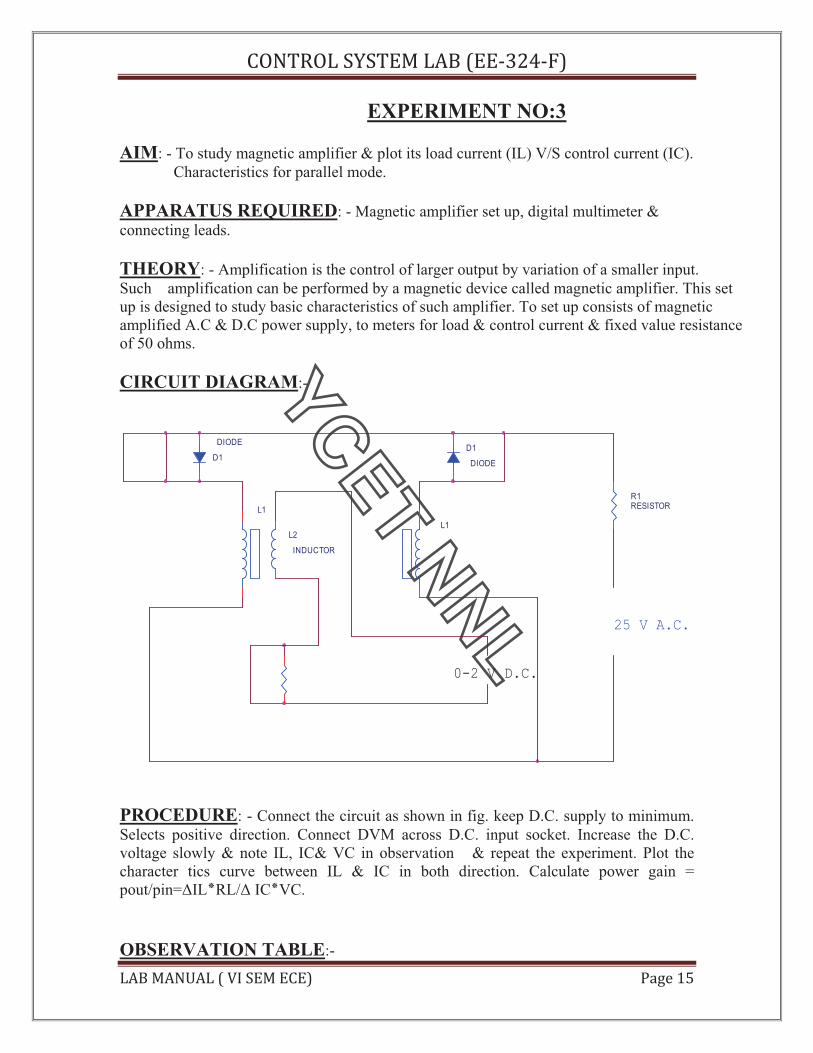
CIRCUIT DIAGRAM:-
D1
DIODE
L1
L2
INDUCTOR
R1
RESISTOR
L1
0-2 V D.C.
D1
DIODE
25 V A.C.
PROCEDURE: - Connect the circuit as shown in fig. keep D.C. supply to minimum.
Selects positive direction. Connect DVM across D.C. input socket. Increase the D.C.
voltage slowly & note IL, IC& VC in observation & repeat the experiment. Plot the
character tics curve between IL & IC in both direction. Calculate power gain =
pout/pin= IL!RL/ IC!VC.
OBSERVATION TABLE:-

!"#$!%&'('#)*&%+,&-))./01.23&
%+,&*+"4+%&-&56&')*&) )3& 789:&@<&
SNO. IC(mA) IL(mA) Vc(+ve)
PRECAUTIONS:-
1. Apply voltage slowly to control winding as the coil may get heated up & burn.
2. Take the reading carefully & accurately.
3. Switch off the set up when not in use.
GRAPH:-
DISCUSSION: - The graph is plotted between control current(IC) and load current
(IL)For positive polarity the control current increases linearly with load current in
forward Direction but for negative polarity the control current increases load current in
reverse direction. This change in direction of control current is due to change in polarity
of control voltage.
QUIZ:- Que.1. What is amplification?
Ans. Amplification is the control of a larger output quantity by the variation of a smaller
input quantity.
Que.2.What is magnetic amplifier?
Ans. Magnetic amplifier is a device which amplifies a small input quantity to a large
output quantity.
Que.3. What is the working principle of magnetic amplifier?
Ans. A magnetic amplifier works on the principle of linkage of induced magneto
Motive Force (mmf).

!"#$!%&'('#)*&%+,&-))./01.23&
%+,&*+"4+%&-&56&')*&) )3& 789:&@=&
Q4. What is magneto-motive force?
Ans. Magneto- motive force in a magnetic circuit is similar to EMF in an electrical
Circuit.
Que.5. What is the basis of selection of core of transformer and number of turns.
Ans. The basis of selection of core of transformer and number of turns is the slope B-H
loop.
Que.6. What is saturable reactor?
Ans. The saturable reactor is a specially wound transformer with three winding
instead of two windings like a common transformer .
Que.7 What is drawback of a magnetic amplifier?
Ans. The main drawback of magnetic amplifier is to control small DC current a Large
number of turns are required which has a greater resistance requires large DC
voltage.
Que.8. How this problem is overcome in a magnetic amplifier?
Ans. This problem is overcome in a magnetic amplifier by self saturation mode.
Que.9. What is the nature of saturable reactor?
Ans. The saturable reactor is inductive nature.
Que.10. What is effect of sudden current application to control winding ?
Ans. If a sudden current is applied to the control winding the current and ampere
Turns of control winding decreases slowly since it has large inductance .
EXPERIMENT NO-4
AIM: To study magnetic amplifier and plot its load current and control current
characteristics for self .

!"#$!%&'('#)*&%+,&-))./01.23&
%+,&*+"4+%&-&56&')*&) )3& 789:&@>&
APPARATUS REQUIRED: Magnetic amplifier set up, digital multimeter and
connecting leads.
THEORY: Self saturation of core is achieved by using two diodes D1 and D2 in series
with L1 and L2 load coils. The successive rectified half wave saturates the core in
opposite direction in few cycles. This leads to flow of current in RL greatly when control
winding in open or there is no current flow. The core does not saturate completely but
operates to bring the core out of saturation. DC current is made to flow in
controlwinding. The control winding has more number of turns than load winding.
Applying a small DC current which oppose the magnetic flux caused by self saturation
tends to cut off produced mmf in load magnetic path. This causes to increase inductance
in l load winding and the voltage drop across then tends to rise which result in decrease
in AC current in RL.If the polarity of DC current is reversed then the saturation of core
takes place in opposite direction.
PROCEDURE: Connect the circuit as shown in fig. keep DC voltage to minimum.
Select positive direction and switch ON the power. Increase the control current slowly
and note the IL, Ic and Vc in observation table. Bring DC voltage to minimum, select
negative. direction and repeat the characteristics curve in both direction. Calculate power
gain
P (gain) = P(out)/P(in) or " IL *RL/"Ic*Vc
CIRCUIT DIAGRAM:
D1
DIODE
L1
L2
INDUCTOR
R1
RESISTOR
L1
0-2 V D.C.
D1
DIODE
25 V A.C.
OBSERVATION TABLE
S.No Ic(mA) IL(mA) Vc(+ve)
1.
2.
3.
4.

!"#$!%&'('#)*&%+,&-))./01.23&
%+,&*+"4+%&-&56&')*&) )3& 789:&@?&
5.
S.No Ic(mA) IL(mA) Vc(-ve)
1.
2.
3.
4.
5.
PRECAUTION : 1. Apply voltage slowly to control winding as the coil may get heated up and burn.
2. Take the reading carefully and accurately.
3. Switch off the set up when not in use.
GRAPH:-
DISCUSSION:-
The graph is plotted between load current and control current. for positive polarity the
Control current rises in the forward direction with rise in load current where as for
negative polarity the control current decreases in the reverse direction with rise in load
current .This is due to the self saturation of the magnetic core .
QUIZ:-
Que.1. What are the modes of operation of the magnetic amplifier?
Ans. The magnetic amplifier operates in two modes Series-parallel mode and Self
saturation mode.

!"#$!%&'('#)*&%+,&-))./01.23&
%+,&*+"4+%&-&56&')*&) )3& 789:&0A&
Que.2. What is the value load resistance RL for magnetic amplifier?
Ans. The value of load resistance RL for magnetic amplifier is 50 ohms Fix.
Q.3. What is power gain in magnetic amplifier?
Ans. The power gain in magnetic amplifier is the ratio of output power to Input power.
Que4. What is current gain in magnetic amplifier?
Ans. The current gain in magnetic amplifier is the ratio of load current to Control
current .
Que.5. What is core saturation?
Ans. When MMF in a coil is varied due to a varying current it causes the Magnetization
to approach to a limit called saturation.
Que.6. What is the direction of windings in the securable reactor?
Ans. In a securable reactor the two windings are anti- phase with each Other.
Que.7. How self saturation is achieved in a magnetic amplifier ?
Ans. The self saturation of core is achieved by using two rectifier diodes D1 & D2 in
series with load coil L1 & L2 .
Que.8. How the magnetic core is brought out of saturation?
Ans. The core is brought out of saturation by passing a current through Control
winding.
Que.9. Which winding has more number of turns?
Ans. The control winding has more number of turns than the load Winding.
Que.10. Between which parameter graph is plotted for magnetic amplifier?
Ans. The graph is plotted between load current and control current.

!"#$!%&'('#)*&%+,&-))./01.23&
%+,&*+"4+%&-&56&')*&) )3& 789:&0@&
EXPERIMENT NO. 5 AIM: - To study of synchros (transmitter/ Receiver) system.
APPARATUS REQUIRED: - Synchro Tx & Rx set, A dual trace CRO and
connecting leads.
BRIEF THEORY: - The synchro Transmitter/ Receiver demonstrator unit is
designed to study of remote transmission of position in AC servomechanism. These are
also called as torque Tx and Rx. The unit has one pair of Tx –Rx synchro motors
powered by 60 V AC inbuilt supply. The synchro Tx has dumb ball shaped magnetic
structure having primary winding upon rotor which is connected with the line through set
of slip rings and brushes. The secondary windings are wound in slotted stator and
distributed around its periphery.
CIRCUIT DIAGRAM:-
DAMPING
STATORSTATOR
RECEIVER
com S1 S2 S3 R1 R2 Ref.
A.C
0 0 0 0 0 0 0
TRANSMITTER
ROTOR
PROCEDURE:-
The experiment is completed is in three parts
1. To study of synchro Tx in terms of position V/s phase and voltage magnitude
w.r.t. rotor voltage magnitude/ phase. Connect the circuit as shown in fig. Note
the o/p Vpp and its phase angle either same as reference o/p or out of phase for

!"#$!%&'('#)*&%+,&-))./01.23&
%+,&*+"4+%&-&56&')*&) )3& 789:&00&
each stator winding. Rotate Tx dial in 30 steps and note voltage magnitude and
phase w.r. t. input as reference. Prepare an observation table.
2. To study synchro Tx/Rx as an Error detector. Connect the circuit as shown in fig.
Start from 60 or 90 and note the Rx R2 o/p voltage and phase.
3. To study of remote position indication system using synchro-Tx and Rx. Connect
the circuit as shown in fig. Keep Tx dial at 0 and watch Rx dial if there is any
error removes it. Increase Tx from 30 to 330 in steps of 30 and note the Rx
position record the observation in a table and find the difference between Tx and
Rx dial position.
OBSERVATION TABLE:-1
S.No. Angular
Position in
Deg. Tx
Magnitude
Phase S1
Magnitude
Phase S2
Magnitude
Phase S3
OBSERVATION TABLE: - 2
S.No. Angular Position in deg.
Tx
Angular Position in deg.
Rx
OBSERVATION TABLE:-3
S.No. Angular Position
in deg. Tx
Angular Position
in deg. Rx
Difference in
Degree Tx-Rx.
PRECAUTIONS: -
1. Move the transmitter and receiver dials slowly to avoid errors in reading.
2. Take the reading carefully in steady condition.
3. Switch of the setup when not in use.

!"#$!%&'('#)*&%+,&-))./01.23&
%+,&*+"4+%&-&56&')*&) )3& 789:&0/&
QUIZ:-
Que.1.What are synchros?
Ans. Synchros are small motors used for remote transmission of shaft Angular position
in AC servo system.
Que.2. What is use of synchro transmitter and receiver?
Ans. Synchro transmitter receivers are designed to study remote transmission of position
in servo mechanism.
Que.3. What is the basic structure of synchro?
Ans. The basic structure of synchro is wound rotor and wound stator .
Que.4. How the two windings are coupled to each other in synchro ?
Ans. The two windings are mutually coupled to each other in such a way that it gives
substantially sinusoidal variation on a function of shaft angular position .
Que.5. What are the advantages of synchros ?
Ans. The operating speed of synchros is high, they have full 360 degree Rotation with
out electrical break and they are highly reliable.
Que.6 What are advantages of synchros ?
Ans .They have full range in order of 30 degrees.linearity is not much better Than
modern potentiometers.
Que.7. What is the phase displacement of three windings of synchros?
Ans. The three windings of synchros are 120 degrees apart .
Que.8. On what factor does the magnitude and polarity of voltage/phase depend?
Ans. The magnitude and polarity of voltage/phase depends upon the angular Position of
rotor.
Que 9. Where the primary winding is connected?
Ans. The primary winding of synchro transmitter is wound on rotor and is connected to
Reference voltage .
Que.10. Where secondary winding is connected?
Ans.The secondary winding is wound over slotted stator and is distributed Around the
periphery .

!"#$!%&'('#)*&%+,&-))./01.23&
%+,&*+"4+%&-&56&')*&) )3& 789:&01&
EXPERIMENT NO: 6
AIM: To study characteristics of positional error detector by angular displacement of
two servo potentiometers.
APPARATUS: Potentiometer kit, Dual trace CRO and connecting leads
THEORY : Potentiometric transducers are used in control applications. The set-up
has built-in source of +5V dc and about 2Vpp 400Hz AC output. A DVM is
provided to read dc voltage and AC can be read on CRO. The potentiometers are
electrtomechanical devices which contain resistance and a wiper arrangement for
variation in resistance due to displacement. The potentiometers have three terminals.
The reference DC or AC voltage is given at the fixed terminals and variable is taken
from wiper terminals.
CIRCUIT DIAGRAM :
Error Output
port 2
Balace Demodulator
AC Excitation
R1
RESISTOR
AC Excitation
DVM
port 1 R1
RESISTOR

!"#$!%&'('#)*&%+,&-))./01.23&
%+,&*+"4+%&-&56&')*&) )3& 789:&0;&
Error Output
port 2
DC Excitation
R1
RESISTOR
DCExcitation
DVM
port 1 R1
RESISTOR
PROCEDURE :
1. Connect the power and select the excitation switch to DC. Keep Pot.1 to
center=180û.Connect DVM to error output. Turn Pot.2 from 20û to 340û in regular steps.
Note displacement in 0û=#2 and output voltage E as V0. Plot graph between V0 and #e=
#1- #2.
2. Switch ON the power and select excitation switch to AC. Connect one of CRO input
with carrier output socket and ground. Connect other input of CRO with error output
socket. Keep pot.1 fixed at180û and move pot.2 from 20û to 340û. Note displacement in #û
and Demodulator voltage VDM. Plot graph between displacement and demodulator
voltage.
OBSERVATION TABLE:
Sl.No.
Pot.2
position in
û
e=
1- 2
Output
Voltage =
V0
Sl.No.
Pot.2
position in
û
e=
1- 2
Output
Voltage =
V0

!"#$!%&'('#)*&%+,&-))./01.23&
%+,&*+"4+%&-&56&')*&) )3& 789:&0<&
PRECAUTIONS :
1. Select the excitation switch as required, AC or DC. Wrong selection may cause error
experiment or damage the setup.
2. Take the reading carefully.
3. Switch OFF the setup when not in use.
GRAPH:-
DISCUSSION:- The graph is plotted between displacement angle and output voltage. For DC Excitation
the output voltage increases linearly with positive displacement angle and decreases with
negative displacement angle.but for AC excitation it is reverse. The output voltage
increases with negative displacement and decreases with positive displacement angle.
QUIZ:-
Que.1. What are potentiometers?
Ans. Potentiometers are electromechanically devices containing resistance and wiper arrangement for variation in resistance due to displacement .
Que.2. What is use of potentiometric error dectector?
Ans. The potentiometric error dectectors are used to compare the referenceAnd
feedback signal and detect the error.
Que.3. What is error signal?
Ans. The angular displacement between reference signal and feedback signaL is called
error signal .
Que.4.What is effective range of potwntiometer ?
Ans. The effective range of potentiometer is approximately 270 degrees.
Que.5.What is balanced demodulator ?
Ans. The balanced demodulator is provided to produce phase sensitive DC Signal when
potentiometers are fed with AC signal .
Que.6. How many terminals are there in potentiometers ?
Ans. There are three terminals in potentiometers, two are fixed and one isVariable.
Que.7. Where reference voltage is applied ?

!"#$!%&'('#)*&%+,&-))./01.23&
%+,&*+"4+%&-&56&')*&) )3& 789:&0=&
Ans. Reference voltage is applied at fixed terminals .
Que.8. From where the variable output is taken ?
Ans. The variable output is taken from wiper terminals .
Que.9. what is linearity?
Ans. Linearity is defined as the maximum deviation of output from ideal Voltage .
Que.10.What is instrumentation amplifier ?
Ans. The instrumentation amplifier is a high impedence differential amplifier Having
Unity gain.

!"#$!%&'('#)*&%+,&-))./01.23&
%+,&*+"4+%&-&56&')*&) )3& 789:&0>&
EXPERIMENT:-7
AIM:-To study PID controller for level control of a plant.
(a)To observe open loop performance of building block and calibration of PID controls
(b)To study P, PI, PID controller with type 0 system with delay
(c) To study P, PI, PID controller with type 1 system
APPARATUS REQUIRED: PID controller setup, CRO and connecting leads.
THEORY: - The setup is designed to study performance of analog PID controller with
regulated system. The board has built in signal source, DVM, simulated process and thre
adjustable parameters as PID,Pfor proportional gain , I for integrated gain and D for
derivative gain .three socket are given to add or out any parameter PI &D .threr are two
signal sources of squire wave which is adjustable in frequency (10-40 Hz) and amplitude
(0-2 Vpp) and other signal source in shape of triangular wave to sweep CRO in X-
direction. One DC voltage output which is continuously variable between – 2Vand +2V.
CIRCUIT DIAGRAM:-
C(s)
Time constt.Sq. Wave
TO CRO
TO CRO
Int.
P I D P
D
Time constt.
Relay
I
PROCEDURE: P control mode: connect the circuit as shown in the figure. Switch over CRO for XY
mode. Adjust P control to 0.1 and note the X and Y values. Increase the value of P and
note the results in table. Input 1.0 Vpp , squire wave of 50ms . I not connected to adder
and D control at 00. switch over CRO in tigger mode and find out period of oscillation.
Switch over again in XY mode and find out percentage over shoot and steady state error

!"#$!%&'('#)*&%+,&-))./01.23&
%+,&*+"4+%&-&56&')*&) )3& 789:&0?&
PI control mode : connect the circuit as shown in figure set Kp =reading of dial. Kd=00.
input signal of squire wave amplitude = 1Vpp at 20 Hz. Switch over CRO in XY mode.
Increase I in steps and note the reading . find the result of Ki for 10-15 % over shoot with
minimum Ess .
PID control mode : connect the circuit as shown in figure. Input =1Vpp squire wave of
same frequency adjust Kp and Ki as table 1 and 2 . increase Kd in steps and note the Ypp
and Xpp output from CRO. The equation of PID controller is
M(t) = Kp e(t) +Ki e(t) dt+ Kd de / dt
OBSERVATION TABLE :
S NO. Kp Xpp Ypp OSPP ESSPP
PRECAUTIONS:
1. Do not keep CRO in XY mode for long time.
2. Take the reading carefully and accurately.
3. Apply the required signal to the kit to avoid error.
4. Switch off the kit when not in use.
DISCUSSION:-In open loop response the plots are performed between
Magnitude/frequency and phase/frequency. The upper curve is for gain/Frequency raised
to 9.35 db. The middle curve is for frequency and the Lower curve is for phase. This shift
in gain-cross over frequency and phase Margin is due to applied gain KA.
QUIZ:-
Que.1. What for compensation networks are used?
Ans. Compensation networks are used to make appreciable improvement in
transient response and small change in steady- state accuracy.
Que.2. What are the types of compensation networks?
Ans. There are three types of compensation networks, LEAD, LAG and
LEAD- LAG Compensation network.

!"#$!%&'('#)*&%+,&-))./01.23&
%+,&*+"4+%&-&56&')*&) )3& 789:&/A&
Que.3. What is the use of all pass filter?
Ans. The all pass filter is used to observe phase/frequency response.
Que.4. What is use of inverting amplifier?
Ans. The inverting amplifier is used to invert the phase oh feed back signal.
It has gain K= -1.
Que.5. What are the responses of compensation network?
Ans. Compensation network has two responses, open loop response and Close loop response.
Que.6. What is use of LEAD compensation?
Ans. LEAD compensation is used to improve the phase margin to any desired
Value for a specified error constant.
Que.7. What is the use effect of LEAD compensation on the system?
Ans. It increases the bandwidth and makes the speed response faster.
Que.8. What is the effect of LAG compensator on the system?
Ans. It reduces the bandwidth and slows down the speed response.
Que.9. What is use of LAG compensation?
Ans. LAG compensation is used for high order system with large error
Constant and large bandwidth.
Que.10. What is process or plant?
Ans. It consists of an active network simulation of second order system
Its transfer function is K/(St+1).

!"#$!%&'('#)*&%+,&-))./01.23&
%+,&*+"4+%&-&56&')*&) )3& 789:&/@&
EXPERIMENT NO. 8
AIM:- To study basic open loop and close loop control systems.
Control System :-
A control system is a combination of elements intended to act together to accomplish an
objective. Control systems are classified into two general categories. Open loop and
closed loop control system. The distinction is determined by the control action, which is
that quantity responsible for activating the system to produce the output.
Open loop control system:-
An open loop control system is one in which the control action is independent of the
output. The important features of open loop control system are:-
(1) Their ability to perform accurately is determined by their calibration, which implies
to establish the input-output relation to obtain a desired system accuracy.
(2) They are not generally troubled with problems of instability.
BLOCK DIAGRAM:-
Input( Command) Output ( Controlled)
signal Variable Speed
force
Examples of open loop control system:-
1. A man working on a road with his eyes closed is an example of open loop control
system. The major components in walking are the brain, the eyes and the feet. The
input may be chosen as desired work direction and the output actual work direction.
The control action is determined by the eyes which detect the difference between
input and output and send information to brain. Since the eyes are closed therefore
the system is open loop.
2. Another example of open loop control system is an electric automatic coffee maker.
One possible input for coffee maker is amount of coffee used. In addition most
coffee makers have a dial which can be set for weak, medium or strong coffee. This
setting usually regulates a timing mechanism. There for brewing time of coffee is
another possible input and the output of any coffee maker can be chosen as coffee
strength.
CLOSE LOOP CONTROL SYSTEM:-
Accelerator
Pedal
Engine Vehicle

!"#$!%&'('#)*&%+,&-))./01.23&
%+,&*+"4+%&-&56&')*&) )3& 789:&/0&
A close loop control system is one in which the control action is some how dependent of
the output. Close loop control systems are commonly called feedback control system.
Feedback is that characteristics of close loop control system which differentiates it from
open loop. It is the property of closed loop system which permits the output to be
compared with the input. So that appropriate control action maybe formed as a function
of input and output.
Important features of feedback are:-
1. Reduced effects of non linearites and distortion.
2. Increased accuracy.
3. Increased bandwidth.
4. Reduced sensitivity of the ratio of output to input to variations in system
characteristics.
5. Tendency towards oscillation or instability.
BLOCK DIAGRAM:-
Reference Error Controlled Output
Input
Examples of closed loop control system:-
1. A man working on a road with his eyes open is an example of closed loop control
system. As eyes can distinguish between the desired walk direction and actual walk
direction and make the necessary correction therefore the system is closed loop.
2. Another example of closed loop control system is an automatic toaster. In which
each heating element supplies same amount of heat to both sides of the bread. And
toast quality can be determined by its color. The toaster is initially calibrated for a
desired toast quality which needs no re-adjustment. The toaster is automatically
switched off when the sensor sees the desired color with the help of feedback
linkage which may be electrical or mechanical. Since the output (color of toast ) is
dependent on input ( temperature setting) there for the system is closed loop.
QUIZ:-
Qur.1 What is control system?
Ans It is combination of elements intended to act together to accomplish an objective.
Que.2 How control system is classified?
Ans Control systems are classified as open loop and close loop open control system.
Que.3 What is open loop control system?
Ans A system in which control action is independent of output.
Que.4 What is closed loop control system?
Control
Elements
Plant
Feedback Path
Elements

!"#$!%&'('#)*&%+,&-))./01.23&
%+,&*+"4+%&-&56&')*&) )3& 789:&//&
Ans A system in which the control action is dependent on the output.
Que.5 What are the main features of open loop control system?
Ans Ability to perform accurately and free from troubles of instability.
Que.6 What are the main features of close loop control system?
Ans Reduced distortion and increased accuracy and bandwidth are the main features of
close loop control system.
Que7. Give the examples of open loop and closed loop system?
Ans. In old Air conditioning system, the systems used to work at certain interval without
observing the room temperature. But in modern Air Conditioning System, the system
senses the room temperature by using temperature sensor,if temperature exceeds certain
limit then only the system starts cooling. So, old systems are example of open loop control
and new systems are example of closed loop control.
Que 8. What is meaning of feedback?
Ans. Process in which the effect or output of an action is 'returned' (fed-back) to modify
the next action. Feedback is essential to the working and survival of all
regulatory mechanisms found throughout living and non-living nature, and in man-
made systems such as education system and economy.
Que9.What is error?
Ans. The difference between the SP and the PV. When errors are detected, the controller
sends instructions to the control system to adjust the output to compensate.
Que10.What is gain?
Ans. The ability of the control system to increase the power or amplitude of its signal.

!"#$!%&'('#)*&%+,&-))./01.23&
%+,&*+"4+%&-&56&')*&) )3& 789:&/1&
EXPERIMENT NO:9
AIM: To study water level control using industrial PLC
APPARATUS REQUIRED: -Trainer kit ST2421 PLC trainer ST2401, ST2402 and
connector.
THEORY:
Water level controlling is shown with the help of LEDs. The apparatus is connected with
output of PLC. Two valves for filling and draining water are shown, for indicating
ON\OFF condition of valve LED is used. Filling of tank indicated by two sensors,
positioned to sense maximum and minimum water levels of tank.
CONNECTION DIAGRAM:-
PIN CONFIGURATION OF CONNECTOR:-
PROCEDURE:

!"#$!%&'('#)*&%+,&-))./01.23&
%+,&*+"4+%&-&56&')*&) )3& 789:&/;&
1. First the valve!1 will open (LED is ON),then water level will increase (row of LEDs will glow)
2. As level reaches above sensor!1, sensor LED will glow. As water level reaches above sensor!2
valve!1 gets closed.
3. After some delay valve!2 will get ON , which will drain water. As soon as water level goes below
sensor!1, valve!2 will close. And same process will go on.
PRECAUTIONS:- 1. Use only the mains cord designed for this instrument
2. To avoid fire or shock hazards, observe all ratings and marks on the instrument.
3. Use the fuse type and rating specified for this instrument.
4. Do not operate in wet / damp conditions.
5. Do not operate in an explosive atmosphere.
6. Keep the product dust free, clean and dry.
QUIZ:-
Q.1 What is PLC?
Ans. A programmable logic controller (PLC) or programmable controller is a digital computer
used for automation of electromechanical processes, such as control of machinery on factory
assemble lines, amusement rides, or light fixtures.
Q.2 What is full form of PLC?
Ans. The full form of PLC is Programmable Logic controller.
Q.3 What are the applications of PLC ?
Ans. Manufacturing Industry, Travel Industry, Textile Industry etc.
Q.4 Which is the famous programming language is used in PLC?
Ans. Ladder logic is mainly used in PLC.
Que5.What are the advantages of PLC.
Ans. Flexible, Correcting Errors, Space Efficient, low cost.
Que6. What are the most popular PLC's used on the packing industry?
Ans:Packaging industry PLC's, most notably cosmetic and pharamaceutical packaging
machinery
Q.7 Why PLC is different from other Computers?
Ans. The main difference from other computers is that PLCs are armored for severe conditions
(such as dust, moisture, heat, cold) and have the facility for extensive input/output (I/O)
arrangements.
Que8.What is DCS?

!"#$!%&'('#)*&%+,&-))./01.23&
%+,&*+"4+%&-&56&')*&) )3& 789:&/;&
Ans. DCS is Distributed Control Systems which is used to control very big plants by using
simple GUI screens.PLCs are interfaced with DCS for interlocking.
Que9.What is SCADA?
Ans. SCADA is Supervisory Control and Data Aquisition which is used to control and Monitor
small number of Equipments in a field.
Que10.What is the difference between PLC and Relay?
Ans. PLC is the much less complex than large relay based system.Also PLC is the very
flexible due to network architecture compare to relay panel.

!"#$!%&'('#)*&%+,&-))./01.23&
%+,&*+"4+%&-&56&')*&) )3& 789:&/<&
EXPERIMENT NO. 10
AIM: - To study motion control of a conveyor belt using a industrial PLC
APPARATUS REQUIRED: - Trainer kit ST2425, Connecting wires.
THEORY:-
Conveyors are basically material handling equipments. Conveyors used for moving
materials over a fixed path. There is a broad range of types of conveyor systems. Wheel
conveyor, roller conveyor, chain conveyor, Magnetic conveyor, pneumatic conveyor are
the major types.
ST2425 Conveyor Control by PLC is a Flat Belt Conveyor system. It consists of two
sensors one is IR sensor and other is proximity sensor. Belt is driven by a DC motor.
Output of proximity sensor, output of IR sensor are the inputs of PLC and motor, motor
direction, buzzer are the outputs of PLC. Some additional I/Os also given for users.
PANEL DIAGRAM:-
PROCEDURE:-
There are two modes of operation of ST2425 one is “Auto Mode” and other is
“Manual Mode”.
Auto Mode:
1. Switch on the Trainer
2. The switch indicated by arrow should be placed in Auto mode
3. Connect +24 V & +5 V supplies
4. Connect inputs and outputs to PLC
5. Set the total count
6. Place containers on the belt randomly
Manual Mode:
1. Switch on the Trainer
2. The switch indicated by arrow should be placed in Manual mode

!"#$!%&'('#)*&%+,&-))./01.23&
%+,&*+"4+%&-&56&')*&) )3& 789:&/=&
3. You can change the direction of motor by using push buttons
PRECAUTIONS:- 1. Make sure that connections are tight.
2. Properly connect inputs and outputs to PLC
3. Switch off the set when not in use.
QUIZ:
Q.1 What is control system?
Ans It is combination of elements intended to act together to accomplish an objective.
Q.2 What is full form of PLC?
Ans. The full form of PLC is Programmable Logic controller.
Q.3 What are Conveyors?
Ans. Conveyors are basically material handling equipments. Conveyors used for moving
materials over a fixed path.
Q.4 Why PLC is different from other Computers?
Ans. The main difference from other computers is that PLCs are armored for severe conditions
(such as dust, moisture, heat, cold) and have the facility for extensive input/output (I/O)
arrangements.
Q.5 What are is proximity sensor.
Ans. A proximity sensor is a sensor able to detect the presence of nearby objects without any
physical contact.
Q.6 Where are the conveyors used?
Ans. The conveyors are used:When material is to be moved frequently between specific points,
to move materials over a fixed path and When there is a sufficient flow volume to justify
the fixed conveyor investment.
Que7.What is the difference between PLC and Relay?
Ans. PLC is the much less complex than large relay based system.Also PLC is the very
flexible due to network architecture compare to relay panel.
Que8.What is the full form of PLC
Ans. The full form of PLC is Programmable Logic controller.
Que.9 What are the applications of PLC ?
Ans. Manufacturing Industry, Travel Industry, Textile Industry etc.
Que10 What is the difference between the PLC and other computers.
Ans.The main difference from other computer is that PLCs operate in industrial
environments(dust,moisture,heat,cold)and have multiple input/output terminals.
!"#$!%&'('#)*&%+,&-))./01.23&
%+,&*+"4+%&-&56&')*&) )3& 789:&/>&
EXPERIMENT NO. 11
AIM: To study LEAD LAG compensator and draw magnitude and phase plot.
APPRATUS REQUIRED: lead lag compensator kit, CRO, and connecting leads.
THEORY: Compensation network are often used to make improvement in transient response and
small change in steady state accuracy. The set up is divided in to three parts. Signal
source: It has sine wave of 10-1200 Hz. Of 0-8 Vpp, Square wave of 20, 40 and 80 Hz of
0-2 Vpp. Trigger is available for trigger of CRO in external trigger mode. The amplitude
is 1.2 Vpp. There are three compensation circuits as lag, Lead and Lag-Lead with transfer
function. The set up has two DC regulated power supply for signal source and systems.
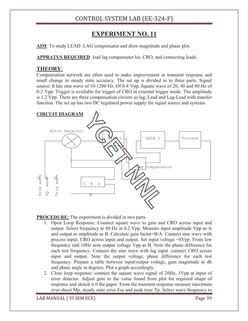
CIRCUIT DIAGRAM
C R O
SQ. wave
Lag Compensator
Sine wave
ProcessGAIN 1 GAIN 2
Error Detector
Trig wave
PROCEDURE: The experiment is divided in two parts.
1. Open Loop Response: Connect square wave to gain and CRO across input and
output. Select frequency to 80 Hz at 0.2 Vpp. Measure input amplitude Vpp as A
and output as amplitude as B. Calculate gain factor=B/A. Connect sine wave with
process input, CRO across input and output. Set input voltage =8Vpp. From low
frequency end 10Hz note output voltage Vpp as B. Note the phase difference for
each test frequency. Connect the sine wave with lag input .connect CRO across
input and output. Note the output voltage, phase difference for each test
frequency. Prepare a table between input/output voltage, gain magnitude in db
and phase angle in degrees. Plot a graph accordingly.
2. Close loop response: connect the square wave signal of 20Hz, 1Vpp at input of
error detector. Adjust gain to the value found from plot for required shape of
response and sketch it 0 the paper. From the transient response measure maximum
over shoot Mp, steady state error Ess and peak time Tp. Select wave frequency to

!"#$!%&'('#)*&%+,&-))./01.23&
%+,&*+"4+%&-&56&')*&) )3& 789:&1?&
40Hz, 1Vpp and adjust gain control to 60%. Not gain control setting. Trace wave
form on paper with record of Ess, Mp, and Tp. Select frequency to 80Hz and
adjust gain control for minimum Ess 0. Trace wave form with Mp and Tp.
connect process with lag compensator and gain 2. Set square wave frequency to
20Hz, 1Vpp at error detector input . Adjunct gain control to for similar Ess. Note
gain to from dial setting. Trace the wave form on paper with record of Mp, Tp and
Ess.
OBSERVATION TABLE :
S.NO. A Vpp B Vpp GAIN dB PHASE ANGLE
GRAPH:
QUIZ: Que.1. What is the use of adder at the input of PID controller?
Ans. Adder is used to sum up the reference signal and feed Back signal.
Que.2. What is the use of time delay?
Ans. Time delay generates a delay of 1.3 seconds between input And output.
Que.3. What is uncommitted amplifier?

!"#$!%&'('#)*&%+,&-))./01.23&
%+,&*+"4+%&-&56&')*&) )3& 789:&1@&
Ans. It is an operational amplifier configurated as phase inverter.
Its gain constant is= -1.
Que.4. What is the range of frequency and amplitude of square wave Source?
Ans. The range of frequency is from 10 to 40 hz and amplitude is From 0 to 2 Vpp.
Que.5. What is range of voltage source?
Ans. The range of voltage source is from -2 to +2 v.
Que.6. What is equation of PID controller?
Ans. The equation of PID controller is
m(t) = Kp e(t)+Ki e(t)dt+Kd de(t)/dt.
Que.7. What is the transfer function of PID controller?
Ans. The transfer function of PID is G(PID) = m(s)/E(S).
Que.8. What are the methods of tuning PID?
Ans. There are two methods of tuning PID, process reaction curve
method and continuous cycling method.
Que.9. What is the main advantage of derivative error compensation?
Ans. Main advantage of this compensation is that as the damping
increases due to compensation , system settling time reduces.
Que.10. How derivative output compensation is obtained?
Ans. Derivative output compensation is obtained by means of a Tachometer
feedback.
!"#$!%&'('#)*&%+,&-))./01.23&
%+,&*+"4+%&-&56&')*&) )3& 789:&10&
EXPERIMENT NO:-12
AIM: To study control action of light control system (a) the study of lamp response (b) the
controller with amplifier in closed loop (c) and the introduction of P-I controller to improve the
response.
APPARATUS REQUIRED: Dual trace CRO, DVM
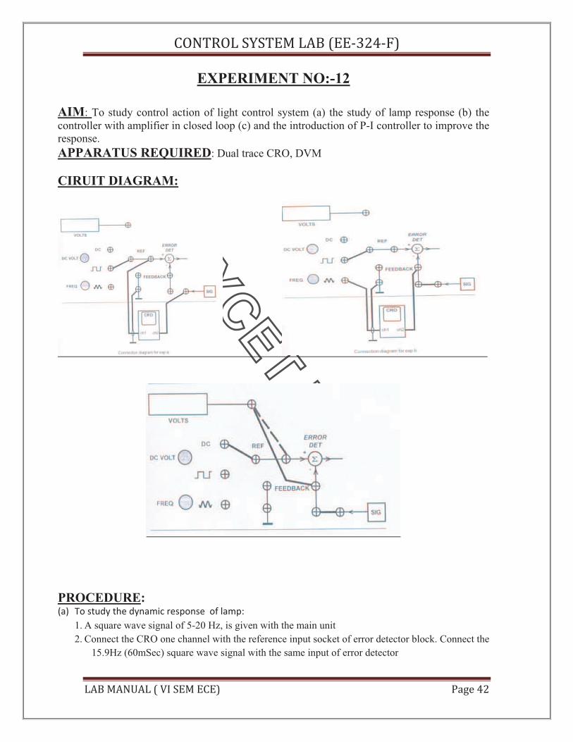
CIRUIT DIAGRAM:
PROCEDURE: (a) To study the dynamic response of lamp:
1. A square wave signal of 5-20 Hz, is given with the main unit
2. Connect the CRO one channel with the reference input socket of error detector block. Connect the
15.9Hz (60mSec) square wave signal with the same input of error detector

!"#$!%&'('#)*&%+,&-))./01.23&
%+,&*+"4+%&-&56&')*&) )3& 789:&1/&
3. Connect the other channel of CRO with the signal conditioner output socket. Select the amplifier
mode from the selector switch and keep the disturbance switches in off condition.
4. Switch on the power supply and adjust the amplifier gain select to number 6,means the amplifier
is selected to amplifying factor 6.
5. Adjust the CRO time base and amplitude controls toobtain the steady waveform pattern showing
the input and output signal. Note the output signal is taken from the sensor signal conditioner
which is negative in polarity thus its inverted form is applied as the lamp response signal .
6. Observe and trace the response curve of both the actuating signal and the lamp output. Note the
+ve lead signal of square wave is 60 mSec duration.
7. Decrease the amplifier gain to 4 and observe its effect upon the lamp output response. It is
observed that the amplitude of lamp intensity is decreased, since the sensor output is directly in
proportion of lamp intensity.
(b) To study the controller with amplifier in closed loop
1. Now connect the feedback path to form the close loop circuit. Connect the signal conditioner
output with the feedback socket of error detector block. Unplug the square wave signal and
connect the reference voltage socket there with the error detector block input.Connect the given
DVM lead with the error detector socket (remove CRO).
2. Select the amplifier gain =1. Adjust the reference voltage to 4.00 volt dc. Now connect the DVM
socket with feedback socket. Note the voltage there. Find out the steady state error as Vr-Vf.
3. Increase the amplifier gain in steps and note the feedback voltage and find out ess.
4. Keep the amplifier gain at 10. Now connect the CRO in place of DVM connect the square wave
signal at the ref. input of error detector block while remove the dc reference from there.
Connect the CRO other channel with triangular wave(X input channel) signal. Select X-Y mode
of CRO . Adjust the waveform position to obtain full screen waveform pattern. Note that the
overlap shown in the waveform.
5. As the input signal has fixed time duration 50 msec, the timing of delay and overshoot is easily
measured..Select different gain and observe its effect upon the overshoot and ess.
(c) To study the introduction of P-I controller to improve the response.
1. Now switchover to the P-I control where the sockets connections are as the step b.4.Adjust CRO
controls to obtain the stationary waveform pattern .Observe the first overshoot and response of
P-I controller.
2. Switch over to CRO normal operation. Connect the X input channel of CRO with the reference
input of error block input. A square wave signal with the the lamp output response inform of
feedback signal appear upon screen.
3. Observe the time lag (produced by the lamp) and the P-I controller response.
4. Now remove the CRO and connect the DVM at error detector reference input. Connect the same
input with the dc reference socket. Adjust the reference for +4.00 volt dc.
5. Connect the DVM at the feedback socket. Note the output voltage there. Note the output voltage
there. Note the feedback voltage is in propotion of light intensity. Find out the steady state error.
WAVEFORMS

!"#$!%&'('#)*&%+,&-))./01.23&
%+,&*+"4+%&-&56&')*&) )3& 789:&11&
PRECAUTIONS:
1. Use only the main cord designed for this instrument
2. To avoid fire or shock hazards, observe all the ratings.
3. Use the fuze type and the rating specified for this instrument
4. Don’t operate in wet /damp conditions
5. Do not operate in an explosive atmosphere
6. Keep the product dust free, clean and dry
QUIZ:-
Que.1. What is full form of PID?
Ans. P stands for proportional, I stand for integrated and D stands for
Derivative gain.
Que.2. What is derivative error compensation?
Ans. A system is said to have derivative error compensation when the
generation of its output depends in some way on its rate of change of
actuating signal .
Que.3. What is integral error compensation?
Ans. A system is said to have integral error compensation if its output
Response depends in some way upon the integral of its actuating
Signal.
Que.4. What is effect of integral error compensation on the system ?
Ans. Integral error compensation changes a second order system to a
Third order system.
Que.5. How derivative error compensation is obtained ?
Ans. Derivative error compensation is obtained by using an amplifier
Which provides a signal having two terms, one proportional to
To derivative of actuating signal and other proportional to the actuating
Signal itself.
Que.6. How integrating error compensation is obtained?

!"#$!%&'('#)*&%+,&-))./01.23&
%+,&*+"4+%&-&56&')*&) )3& 789:&1A&
Aue. Integrating error compensation is obtained by introducing a controller
Which contains two terms, one is proportional to the integration of
Actuating- signal and other proportional to actuating signal itself.
Que.7. Where PID is used?
Ans. PID is used in process industries for feedback gain.
Que.8. If dynamic model is not known then PID is tuned experimentally by
Simulation.
Que.9. How PID is tuned if dynamic model is known?
Ans. If dynamic model is known then PID is tuned by Ziegelar-Nicholas Method.
Que.10. What time response specifications are required to be met by the control
System?
Ans. Three time response specifications are to be met by the control system,
Steady- state accuracy, damping factor and settling time.

!"#$!%&'('#)*&%+,&-))./01.23&
%+,&*+"4+%&-&56&')*&) )3& 789:&1;&
EXPERIMENT NO:-13
EXPERIMENT: Determine transpose, inverse values of given matrix.
APPARATUS REQUIRED: Computer with MATLAB software
THEORY: Open M-files
And start performing the following
Entering matrices into Matlab is the same as entering a vector, except each row of
elements is separated by a semicolon (;) or a return:
B = [1 2 3 4;5 6 7 8;9 10 11 12]
B =
1 2 3 4
5 6 7 8
9 10 11 12
B = [ 1 2 3 4
5 6 7 8
9 10 11 12]
B =
1 2 3 4
5 6 7 8
9 10 11 12
Matrices in Matlab can be manipulated in many ways. For one, you can find the
transpose of a matrix using the apostrophe key:
C = B'
C =
1 5 9
2 6 10
3 7 11
4 8 12
To find the inverse
Let us take
E = [1 2;3 4]
The inverse of a matrix:
X = inv(E)
X =
-2.0000 1.0000
1.5000 -0.5000

!"#$!%&'('#)*&%+,&-))./01.23&
%+,&*+"4+%&-&56&')*&) )3& 789:&1<&
QUIZ:
Que1: What is MATLAB?
Ans: MATLAB is the name used to refer to the class of matrix calculator environments
derived from the first, called MATLAB
Que2:What can we use MATLAB for?
Ans: Matlab is to be utilized for data extraction,data analysis and data processing,it is
further utilized for some statistical task to analyze the behavior of the system by
plotting.it is used to generate stimulus for verification of the system.
Que3: Explain The MATLAB mathematical function library?
Ans. This is a vast collection of computational algorithms ranging from elementary
functions like sum, sine, cosine, and complex arithmetic, to more sophisticated functions
like matrix inverse, matrix eigenvalues, Bessel functions, and fast Fourier transforms
Que4.What is transpose of matrix
Ans: Let A be an m * n matrix. Then At, the transpose of A, is the matrix obtained by
interchanging the rows and columns of A.
Que5 What is inverse of matrix?
Ans: It is defined as Let I = [e1 e2 … en] be the nxn identity matrix. Let A be an nxn
matrix. A nxn matrix, B, is called and inverse of A if and only if AB = I and BA = I. B is
often written as A-1.
Que 6: On what machines Matlab should be run?
Ans : Run it from sthelens, and only if sthelens is down, from cher, orsay or tiree. It
works on other machines too, but some of the other machines have older versions of the
OS and core dump upon exiting from matlab. Some other local machines with new setups
work fine. Try your local machine. Matlab is blocked from running on the servers.
Que 7: Can we run Matlab without graphics?
Ans.Sometimes you may want to run scripts which contain plotting commands without
displaying the plots and without going into the script to comment out the commands.
Que8. Explain The MATLAB working environment?
Ans. This is the set of tools and facilities that you work with as the MATLAB user or
programmer. It includes facilities for managing the variables in your workspace and
importing and exporting data. It also includes tools for developing, managing, debugging,
and profiling M-files, MATLAB's applications.
Que9. How to add noise to an image in Matlab?
Ans. The function noise.m, now installed on ashland too, adds Gaussian, uniform, salt
and pepper, additive or multiplicative noise to an image.
Que10. Explain The MATLAB mathematical function library?
Ans. This is a vast collection of computational algorithms ranging from elementary
functions like sum, sine, cosine, and complex arithmetic, to more sophisticated functions
like matrix inverse, matrix eigenvalues, Bessel functions, and fast Fourier transforms

!"#$!%&'('#)*&%+,&-))./01.23&
%+,&*+"4+%&-&56&')*&) )3& 789:&1=&
EXPERIMENT NO:-14
EXPERIMENT: Plot unit step response of given transfer function and find peak
overshoot, peak time.
APPARATUS REQUIRED: Computer with MATLAB
Consider a higher-order system defined by
Using MATLAB, plot the unit-step response curve of this system. Using MATLAB,
obtain the rise time, peak time, maximum overshoot, and settling time.
C(s) = 6.3223s2+ 18s + 12.811
R(s) s4+ 6s
3 + 11.3223s
2+ 18s + 12.811
% ------- This program is to plot the unit-step response curve, as well as to
find the rise time, peak time, maximum overshoot, and settling time.
% In this program the rise time is calculated as the time required for the
%" response to rise from 10% to 90'% of its final value. -------
num = [0 O 6.3223 18 12.811 1;
d e n = [ l 6 11.3223 18 12.8111;
t = 0:0.02:20;
[y,x,t] = step(num,den,t);
plot(t,y)
grid
title('Unit-Step Response')
xlabel('t (set)')
ylabel('0utput y(t)')
r l = 1; while y(r1) < 0.1, rl= r l+ 1; end;
r2 = 1; while y(r2) < 0.9, r2 = r2+l; end;
rise-time = (r2-rl)*O. 02
rise-time =
0.5800
[ymax,tp] = max(y);
peak-time = (tp-1)*0.02
peak-time =
max-overshoot = ymax-l
max_overshoot =
0.6182
s = 1001; while y(s) > 0.98 8( y(s) < 1.02; s = s-1; end;
settlingtime = (s-1)*0.02
settling-time =
10.0200

!"#$!%&'('#)*&%+,&-))./01.23&
%+,&*+"4+%&-&56&')*&) )3& 789:&1>&
QUIZ:
Que1: What do you understand by MATLAB software?
Ans: MATLAB is a high level language and interactive environment that enables you to
interactive environment that enables you to performcomputationally intensive tasks faster
than with traditional programming language.
Que2. What does MATLAB stands for?
Ans: matrix laborartory
Que3. What is transfer function.
Ans. Transfer function is defined as ratio of laplace of output to the laplace of input.
Que4.What is peak overshoot.
Percent overshoot, - The percent overshoot is defined as the amount that the waveform at
the peak time overshoots the steady-state value, which is expressed as a percentage of the
steady-state value.
Que 5. What is Peak time?
Ans. The peak time is the time required for the response to reach the first peak.
Que6.What is settling time
Ans. The settling time is the time required for the amplitude of the sinusoid to decay to
2% of the steady-state value.
Que7.What is rise time
Ans. Time the response takes to rise from 0 to 100%
Que8. What is transient response?
Ans: Transient response mean the response(temporary output voltage change)of the
converter due to load transient.
Que9What is damping ratio?

!"#$!%&'('#)*&%+,&-))./01.23&
%+,&*+"4+%&-&56&')*&) )3& 789:&A?&
Ans: The damping ratio is a dimensionless measure describing how oscillations in a
system decay after a disturbance. Many systems exhibit oscillatory behavior when they
are disturbed from their position of static equilibrium.
Que10.What is steady state system?
Ans:The manner in which the system output behaves as t approaches infinity – the error
after the transient response has decayed, leaving only the continuous response.
.

!"#$!%&'('#)*&%+,&-))./01.23&
%+,&*+"4+%&-&56&')*&) )3& 789:&A@&
EXPERIMENT NO:-15
EXPERIMENT: Plot the pole-zero configurations in s-plane for the given transfer
function
APPARATUS REQUIRED: Computer with MATLAB
PROCEDURE: Plot s-plane grid lines on the root locus for the following system.
You can do this by typing in MATLAB
H = tf([2 5 1],[1 2 3])
Transfer function:
2 s^2 + 5 s + 1
---------------
s^2 + 2 s + 3
QUIZ:
Que1: What do you understand by MATLAB software?
Ans: MATLAB is a high level language and interactive environment that enables you to
interactive environment that enables you to performcomputationally intensive tasks faster
than with traditional programming language.
Que2. What does MATLAB stands for?
Ans: matrix laborartory
Que3.Where can we use MATLAB?
Ans: It is widely used in academic and research institutions as well as industrial
enterprises.
Que4. Name some tool boxes?
Ans: Control tool boxes, fuzzy logic tool boxes.
Que5.What is system requirement for MATLAB?
Ans: 1 GB for MATLAB only,3-4 GB for a typical in typical Installation 1024 MB.
Que6. What is transfer function?
Ans. Transfer function is defined as ratio of laplace of output to the laplace of input.
Que7. What are zeros and poles in control system?
Ans: zeroes are determined by equating the numerator of the transfer function to zero
poles are determined by equating the denominator of the transfer function to zero
zeroes means the o/p at those frequencies is zero while pole means that o/p at that
frequency is infinite(or very large)
Que8: What is Root Locus?

!"#$!%&'('#)*&%+,&-))./01.23&
%+,&*+"4+%&-&56&')*&) )3& 789:&A0&
Ans; Root-Locus allows to graph the locations of the poles and zeros for every value of
gain, by several simple rules.
Que9: What is the stability in control system?
Ans: The stability of a system relates to its response to inputs or disturbances. A system
which remains in a constant state unless affected by an external action and which returns
to a constant state when the external action is removed can be considered to be stable.
Que10. Name some tool boxes in matlab?
Ans: Control tool boxes, fuzzy logic tool boxes.