control rc 20 - sneholt-nilsensneholt-nilsen.dk/wp-content/uploads/2015/11/rc-20.pdf · 8.1.7...
TRANSCRIPT

BalTec Maschinenbau AG
Obermattstrasse 65 CH - 8330 Pfäffikon ZH Phone: +41 (0)44 953 13 33Fax: +41 (0)44 953 13 [email protected] http:\\www.baltec.com
803778.002/ENG
OPERATING INSTRUCTIONS
Control RC 20
for pneumatic machines 081-331
803778.002/ENG

Introduction Control RC 20
2 803778.002/ENG

Control RC 20 Introduction
803778.002/ENG 3
Contents
1 Introduction ............................................................................................................... 5
2 Safety regulations ..................................................................................................... 6 2.1 Introduction.......................................................................................................................................... 6
2.2 Information and symbols ..................................................................................................................... 6 2.2.1 Warning and safety notices ............................................................................................................ 6
2.3 Safety measures ................................................................................................................................. 7
3 Product description .................................................................................................. 8 3.1 Introduction.......................................................................................................................................... 8
3.2 Details RC 20 control unit ................................................................................................................... 9
3.3 Dimensions drawing RC 20 control unit ............................................................................................ 10
3.4 Technical specifications RC 20 control unit ...................................................................................... 10
3.5 Control functions / Terms .................................................................................................................. 11
3.6 Operation of the riveting spindle ....................................................................................................... 11 3.6.1 Rivet initiation ............................................................................................................................... 12 3.6.2 Initiation monitoring ...................................................................................................................... 13
3.7 Overview of abbreviations and symbols ........................................................................................... 14
4 Commissioning ....................................................................................................... 15 4.1 Electric supply ................................................................................................................................... 15
4.2 Initial commissioning ......................................................................................................................... 16
4.3 Superordinate PLC control ................................................................................................................ 17
5 Operation ................................................................................................................. 18 5.1 Switching on the control unit ............................................................................................................. 18
5.2 Main menu RC 20/RC 20A ................................................................................................................ 19 5.2.1 Setup operating mode .................................................................................................................. 20 5.2.2 Single cycle operating mode ........................................................................................................ 21 5.2.3 Auto-cycle operating mode .......................................................................................................... 22 5.2.4 Info menu (Page 1) ...................................................................................................................... 24 5.2.5 Info menu (Page 2) ...................................................................................................................... 25 5.2.6 Tools menu .................................................................................................................................. 26 5.2.6.1 Setup menu ............................................................................................................................. 27 5.2.6.1.1 Coding system for the individual setup parameter sectors ................................................ 27 5.2.6.1.2 Changing setup parameters .............................................................................................. 28 5.2.6.1.3 Setup Table, SW-Version 2.05 A and 2.05 B .................................................................... 29 5.2.6.2 Diagnosis menu ...................................................................................................................... 32 5.2.6.3 History menu ........................................................................................................................... 32 5.2.6.4 Miscellaneous menu ............................................................................................................... 32
5.3 Troubleshooting and error rectification ............................................................................................. 33 5.3.1 Introduction .................................................................................................................................. 33 5.3.2 List of messages <MES> ............................................................................................................. 33 5.3.3 List of error messages <ERR> ..................................................................................................... 34 5.3.4 General errors .............................................................................................................................. 36
6 Options .................................................................................................................... 37 6.1 Initiator lower end position (bridging initiator) ................................................................................... 37 6.1.1 Function ....................................................................................................................................... 37 6.1.2 Factory settings ............................................................................................................................ 37 6.1.3 Switching status monitoring ......................................................................................................... 38 6.1.4 Adjusting monitoring time in setup ............................................................................................... 39
6.2 Change over from operation with two-hand operating unit to operation with foot switch ................. 40 6.2.1 Key switch .................................................................................................................................... 40
Introduction Control RC 20
4 803778.002/ENG
7 Maintenance and repair work ................................................................................ 41 7.1 Introduction ....................................................................................................................................... 41
7.2 Control unit maintenance ................................................................................................................. 41
8 Appendix ................................................................................................................. 42 8.1 Schemata ......................................................................................................................................... 42 8.1.1 Power section RN pneumatic 802870 ......................................................................................... 42 8.1.2 Control section RN pneumatic 802874 ....................................................................................... 43 8.1.3 Connection diagram safety module (SIMOD) 2HMR-SSR 803162 ............................................ 44 8.1.4 Connection diagram safety module (SIMOD) 2HMRS-SSR 803163 .......................................... 45 8.1.5 Connection diagram safety module (SIMOD) AM-SSR 802885 ................................................. 46 8.1.6 Connection diagram safety module (SIMOD) AMS-SSR 802887-a ........................................... 47 8.1.7 Wiring diagram contactor module RN pneumatic 802908 .......................................................... 48
8.2 Spare parts lists ................................................................................................................................ 49 8.2.1 Control unit RC 20, 814337-n ..................................................................................................... 49
9 Index ........................................................................................................................ 53

Control RC 20 Introduction
803778.002/ENG 5
1 Introduction
We are certain that you have made the right choice with our product and thank you for your trust.
For your personal safety
Before carrying out any activities on or with the control unit, please carefully read these operating instructions first, in particular the chapter on "Safety regulations".
Application area of these operating instructions
These operating instructions describe the control unit and provide all information required for safe operation and maintenance of functionality. Please keep these operation instructions available at all times for all persons involved with the riveting machine.
Questions or unclear points
Please contact immediately if you have any questions or unclear points:
- BalTec Maschinenbau AG, Obermattstrasse 65 CH – 8330 Pfäffikon ZH
- BalTec – distributors (see representatives list in the appendix)
Please provide them with the document and page numbers located in the footer and the machine number listed on the title page of operating instructions.
Original language of assembly instructions
These assembly instructions was originally written in German language.
——
© Copyright BalTec Maschinenbau AG – Pfäffikon 2010

Safety regulations Control RC 20
6 803778.002/ENG
2 Safety regulations
2.1 Introduction
The control unit may only be operated by qualified and appropriately trained personnel for safety reasons.
2.2 Information and symbols
2.2.1 Warning and safety notices
The warning and safety notices used in these operating instructions have the following significance:
CAUTION
Indicates a hazard with low risk which, if not avoided, could result in minor or moderate injury.
WARNING
Indicates a possible hazard with medium risk which, if not avoided, could result in death or serious injury.
DANGER
Indicates an immediate hazard with high risk which, if not avoided, will result in death or serious injury.
NOTICE Indicates practical information and tips that permit the best use of machinery, system or equipment.
CAUTION To warn of material damage.

Control RC 20 Safety regulations
803778.002/ENG 7
2.3 Safety measures
CAUTION
Activation of riveting process with foot switch or pulse signal! Danger of hand injuries! The operator has to take safety measures against the intervention in danger area (e.g. separative protection device)!

Product description Control RC 20
8 803778.002/ENG
3 Product description
3.1 Introduction
The riveting machine RC 20 control unit is a control unit designed for the operation of BALTEC radial riveting machines.
The control unit is modular and can be modified according to the applications for the following riveting machines:
Pneumatic riveting machines (single or double riveting machine)
Hydraulic riveting machines (single or double riveting machine)
Control RC 20 Product description
803778.002/ENG 9
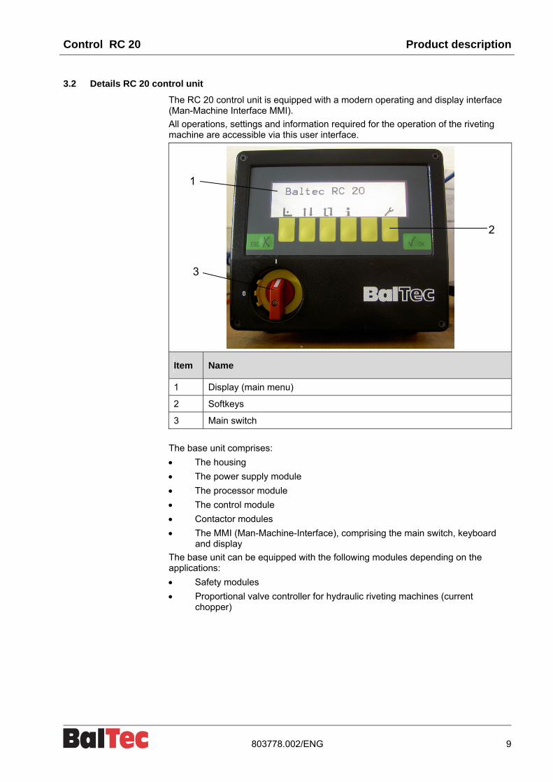
3.2 Details RC 20 control unit
The RC 20 control unit is equipped with a modern operating and display interface (Man-Machine Interface MMI).
All operations, settings and information required for the operation of the riveting machine are accessible via this user interface.
Item Name
1 Display (main menu)
2 Softkeys
3 Main switch
The base unit comprises:
The housing
The power supply module
The processor module
The control module
Contactor modules
The MMI (Man-Machine-Interface), comprising the main switch, keyboard and display
The base unit can be equipped with the following modules depending on the applications:
Safety modules
Proportional valve controller for hydraulic riveting machines (current chopper)
1
2
3

Product description Control RC 20
10 803778.002/ENG
3.3 Dimensions drawing RC 20 control unit
3.4 Technical specifications RC 20 control unit
Construction Al-housing, powder-coated, colours red/anthracite. Internal local separation between power and control section
Degree of protection IP54
Cable entry At the rear via cable glands
Power supply
Three-phase 50/60 Hz Terminals L1, L2, L3, PE Connectable wire cross-section, max. 4mm2 Can be disconnected across all poles with lockable main switch Voltage group 1: 120/230/400/440 V Voltage group 2: 200/346/480/575 V Max. fuse rating of supply lead 16A Primary/secondary galvanically isolated 4kV
Connection See applicable diagram on machine Connection cable with wire cross-section 1.5mm2 as per VDE 0100
Fuses
Internal fine-wire fuses 5x20mm 12 VAC F1 = 1.6 AT 24 VAC F2 = 4.0 AT 24 VAC F3 = 1.0 AT
Inputs/outputs 24 VDC all galvanically isolated 500 V Connection terminals 1.5mm2
Processor Intel 80C32 / 7.3MHZ
Display Graphics-capable display 180x70 mm, 240x64 dots FL backlit
Keyboard Membrane with 8 keys, polyester
Environmental conditionsOperating temperature 0° C - + 50° C Storage temperature - 10° C - + 70° C
Weight Control unit, depending on design, approx. 8.5 - 9.5 kg (Data on label 9 kg)

Control RC 20 Product description
803778.002/ENG 11
3.5 Control functions / Terms
Riveting procedure (RP)
The riveting procedure covers all functions that are required for complete riveting. The riveting procedure consists mainly of two functions, the operation of the spindle motor and the operation of the riveting spindle.
Riveting time (RT)
The duration of the riveting procedure is determined by the riveting time.
Operation of the spindle motor
3 types can be selected in setup:
Permanently switched on
Only switched on during riveting
Only switched on during riveting, but with a switch-off lag of 0.1 to 24.9 seconds which can be selected in setup.
3.6 Operation of the riveting spindle
Pneumatic
Permanent current actuation with 5/2-way valve and spring resetting. The riveting spindle is only driven DOWN. UP is by means of the currentless valve with spring resetting.
Hydraulic
Permanent current actuation with 4/3-way valve and spring resetting (center position currentless). The riveting spindle is driven UP and DOWN. The upper end position is monitored by an initiator. The valve is switched up in the upper position.
With Rapid speed/Working speed (model series 481)
With restrictor valve. The riveting spindle is driven UP and DOWN. The restrictor valve is actuated with the output "Rapid speed/Working speed".
Valve currentless = Work operation
Valve active = during DOWN movement to "lower" initiator
Hydraulic proportional
With way-valve and proportional restrictor. The function is the same as the Rapid speed/Working speed.

Product description Control RC 20
12 803778.002/ENG
3.6.1 Rivet initiation
To initiate riveting "Spindle valve DOWN", several elements are involved for safety reasons:
Riveting actuation
Control contact manually activated or by external control unit
Foot contact (foot switch, etc.)
Two-hand contact
Safety circuit
Optional equipment for safety switches such as light barriers, door monitoring, foot mats, etc.
Safety module SIMOD
One of the following safety modules can be used according to the safety requirements.
Available:
SIMOD AM / AMS for riveting actuation via simple control contact (hand/foot switches, external control unit)
SIMOD 2HM / 2HMS for rivet initiation with two-hand operating unit. Type approved module as per MRL Appendix IV.
The modules.... S are equipped with an input for release; they also have a logic system in order to implement pulse actuation, bridging initiator, etc.

Control RC 20 Product description
803778.002/ENG 13
3.6.2 Initiation monitoring
The processor checks the correct function of the riveting initiation and the safety module. If the function is NOK, the WatchDog relay triggers. The riveting initiation is blocked and the error is shown on the display!
Riveting initiation principle drawing
Item Name
1 Riveting initiation
2 Release (optional)
3 Safety
4 Safety module (SIMOD)
5 Emergency stop
6 Function control and monitoring: processor
7 WatchDog (WD)
8 Spindle
9 Table
10 Spindle valve DOWN
11 Table valve
12 Emergency stop

Product description Control RC 20
14 803778.002/ENG
3.7 Overview of abbreviations and symbols
Abbreviations
RP Riveting procedure
RT Riveting time
SUP Setup (user settings)
ERR Error message
MES Messages
Pn Pneumatic riveting machine
Hyd Hydraulic riveting machine
Operating symbols
Main switch
Disconnection of mains supply at all poles
Green keys
Confirm, Accept, ENTER
Cancel, Back, Exit
Symbols on the display (yellow keys)
Setup operating mode
Single cycle operating mode
Auto-cycle operating mode
Increase/reduce values (riveting time, code, etc.)
Info (Information)
Switches the Process Controller on/off (option)
Tools (utility programs)
Motor ON / OFF
Scroll page down / page up
Cursor up / down
Double functions (simultaneous key pressing)
and Contrast setting (viewing angle modification) of display
and R Reset error <ERR>
and 0 Reset counter

Control RC 20 Commissioning
803778.002/ENG 15
4 Commissioning
4.1 Electric supply
The control unit is connected to the mains supply via the feed cable.
The feed cable is included in delivery.
Data for electrical connection
Input voltage Max. fuse rating of supply lead
Connection cable specifications
Standard length connection cable
see label 16A 3-phase with ground conductor
5m
DANGER
Electrical hazard!
Electric shock! Operations on the control unit are only permitted with main switch set to “OFF“.
CAUTION Incorrect input voltage can destroy the electrical and electronic components!
Input voltage must comply with the specification on the label or the front page of the riveting machine operating instructions.
NOTICE To avoid interference effects on measuring signal and data lines, the lines from control unit to riveting machine must be installed separately from high voltage current and electromagnetic valve cables.
Install no external devices in the control unit if they send out interference signals.

Commissioning Control RC 20
16 803778.002/ENG
4.2 Initial commissioning
CAUTION Riveting spindle position may be too close to the workpiece holder!
Workpiece holder or form tool could be damaged at actuation of riveting procedure!
Move the riveting unit to the top position!
Procedure:
1. Switch on main switch
2. Wait until machine is ready for operation (main menu will appear on the display)
3. Select "Setup" or "Single cycle" operating mode
"Setup" operating mode
4. Press actuation device
The riveting procedure continues for as long as the actuation device is pressed. The duration is shown on the display and includes the time from the start of the riveting spindle to the termination of the riveting procedure (excluding the return time of the riveting spindle)
"Single cycle" operating mode
4. Use the + / - keys to set the required riveting time
5. Press actuation device
The actuation device must be pressed until the entered riveting time is completed and the riveting spindle is ready for the return stroke. If contact is interrupted beforehand, the riveting procedure will be terminated immediately. The riveting spindle will return to the start position.
If an ERR message appears on the display, see “List of error messages <ERR>".

Control RC 20 Commissioning
803778.002/ENG 17
4.3 Superordinate PLC control
Integration within a superordinate PLC means that the control unit must be opened at the back. Procedure:
Removal
1. Undo screw in main switch and pull main switch out
2. Undo the 4 screws in the corners of the rear panel
3. Pull cover with the chassis panel out approx 50mm
4. Disconnect the A3 cable in the back panel (see diagram 802897)
5. Unplug connector of communication cable (ribbon cable)
6. Pull out cover with the chassis panel
CAUTION When removing and inserting the cover, ensure that the cover of the transformer supply (cardboard) is not trapped or damaged by the housing base!
Actuation (rivet start) takes place via a PLC potential-free relay output to the SIMOD (safety module) type AMS at terminal 51 and 52 (see diagram 802887).
Closing
Assembly occurs in the reverse order.

Operation Control RC 20
18 803778.002/ENG
5 Operation
5.1 Switching on the control unit
The control unit is switched on using the main switch built into the front panel.
CAUTION Danger of hand injuries! After a long standstill the riveting spindle could sink. The riveting spindle will return automatically to the start position after switching-on the control unit!
Start-up
The processor runs through the initialization process and tests the safety conditions. If the processor is working correctly and all safety conditions are met, then the machine is ready for operation.
Machine ready for operation
The main menu appears on the display. It is possible to work, make settings and obtain information in the appropriate operating mode.
Machine not ready for operation
If the machine is not ready for operation, an <ERR> is displayed.

Control RC 20 Operation
803778.002/ENG 19
5.2 Main menu RC 20/RC 20A
Switch on the control unit via the main switch. If no changes have been made to the "Operating mode after switch-on" setup parameter, the main menu will appear.
The required operating mode can be selected with the keyboard. The corresponding menu will appear. The current operating mode is shown top left.
In addition, the menus "Info", “Process-Controller“ and "Tools" can be selected.
Main menu
Tools menu
Info menu
Setup operating mode
Single cycle operating mode
Auto-cycle operating mode

Operation Control RC 20
20 803778.002/ENG
5.2.1 Setup operating mode
In the "Setup" operating mode, the riveting procedure is active as long as the command device (foot switch, 2-hand operation, etc.) is pressed.
Symbol Description of the softkey functions
Selects the "Single cycle" operating mode
Selects the "Auto-cycle" operating mode (only possible when the corresponding setup parameter is activated)
Selects the "Info" menu
Back to main menu
Riveting time
The riveting time is measured and indicated in the display.
Strokes
The strokes implemented are also displayed.
Operating mode after switch-on
In the setup parameter "Operating mode after power on", the control unit can be set so that this operating mode is actuated immediately after the mains voltage is switched on.

Control RC 20 Operation
803778.002/ENG 21
5.2.2 Single cycle operating mode
In the "Single cycle" operating mode the riveting procedure is active during the set riveting time.
The command device (foot switch, 2-hand operation, etc.) must remain active during the riveting time. If it is stopped before the riveting time is complete, the riveting procedure will be interrupted immediately. The interruption will be shown on the display.
Exception: Riveting initiation with pulse input.
After initiation of the riveting procedure, the programmed riveting time runs, independently of the time of the riveting actuation (pulse or permanent).
Symbol Description of the softkey functions
Selects the "Setup" operating mode
Selects the "Auto-cycle" operating mode (only possible when the corresponding setup parameter is activated)
Selects the "Info" menu
Increases riveting time by 0.1 sec.
Reduces riveting time by 0.1 sec.
Back to main menu
Riveting time
The riveting time can be adjusted using the "+" and "-" softkeys.
Strokes
The strokes implemented are also displayed.
Operating mode after switch-on
In the setup parameter "Operating mode after power on", the control unit can be set so that this operating mode is actuated immediately after the mains voltage is switched on.

Operation Control RC 20
22 803778.002/ENG
5.2.3 Auto-cycle operating mode
The "Auto-cycle" operating mode is essentially the same as the "Single cycle" operating mode. The riveting procedure is however automatically repeated after a pause as long as the command device (foot switch, 2-hand operation, etc.) is active or until the "Set strokes" value is reached.
The strokes implemented are also displayed.
By default, the setup parameter for the "Auto-cycle" operating mode is set to disabled.
Symbol Description of the softkey functions
Selects the "Setup" operating mode
Selects the "Auto-cycle" operating mode (only possible when the corresponding setup parameter is activated)
Selects the "Info" menu
Cursor (>) scrolls one line down
Cursor (>) scrolls one line up
After pressing the "OK" key, the corresponding value (riveting time, pause time or set strokes) can be changed with the "+" and "-" keys.
Back to main menu
NOTICE This operating mode is only used for the following applications:
In connection with an appropriately secured rotary indexing table
For demonstration purposes

Control RC 20 Operation
803778.002/ENG 23
Changing the riveting time
If the cursor (>) is positioned on the "Riveting time" line, the riveting time can be changed after pressing the OK key with the softkeys "+" and "-".
Changing the pause time
If the cursor (>) is positioned on the "Pause time" line, the pause time can be changed after pressing the OK key with the softkeys "+" and "-". The maximum pause time input can be set in the applicable setup parameter.
Changing the "Set strokes"
If the cursor (>) is positioned on the "Set strokes" line, the set number of strokes can be changed after pressing the OK key with the softkeys "+" and "-". Once this number of strokes has been reached, the auto-cycle stops and the machine waits for a new riveting initiation.
Operating mode after switch-on
In the "Operating mode after power on" setup parameter, the control unit can be set up so that this operating mode is actuated immediately after the mains voltage is switched on.

Operation Control RC 20
24 803778.002/ENG
5.2.4 Info menu (Page 1)
Display normal Display when reset to 0
Display Description Range
Stroke counter OK
Counts all implemented riveting movements that have not caused an error message
Reset to 0 possible - see below 0 – 99999
Stroke counter ERROR
Counts all implemented riveting movements that have caused an error message
Reset to 0 possible - see below 0 – 99999
Stroke counter Total
Counts all stroke movements
Reset only possible with code (Menu Tools -> Miscellaneous)
0 – 99999
Hours Displays the operating hours (riveting motor)
Reset to 0 possible - see below 0 – 99999.9
Hours Total
Displays the total operating hours (riveting motor)
Reset only possible with code (Menu Tools -> Miscellaneous)
0 – 99999.9
Symbol Description of the softkey functions
Scroll page down / page up
Cursor (>) up / down
Contrast setting (viewing angle) of display
Press key simultaneously with the Cursor up / down key
Symbol Reset to 0
0 1. Select text line (Stroke counter.../Hours...) with Cursor (>)
and press OK
2. Press both keys simultaneously

Control RC 20 Operation
803778.002/ENG 25
5.2.5 Info menu (Page 2)
Display Description
HW: WM XXXXXX - XX Hardware Version
SW: WM XXXXXX – XXXXX
X.XX - XX.XX.XX (Date)
Software Version

Operation Control RC 20
26 803778.002/ENG
5.2.6 Tools menu
Press the "Tool" key to enter the menu. To select the sub-menus, proceed as follows:
1. Use the cursor > to move to the required menu
2. Confirm with OK
3. Enter access code with the + / - keys and confirm with OK
The required menu will appear.
The menu can be exited with ESC.
Menu Function description
Setup Operating and machine settings in the setup table (parameter list)
Diagnosis Display of control states of the internal inputs and outputs
History Display of <MES> and <ERR> messages
--- Reserve
Miscellaneous Reset Pieces Total and Hours Total; Delete History Memory; Initialization setup to default values
Symbol Description
Switching the motor on and off
Selects the "Info" menu
Cursor up / down
Increase/reduce value
Back to main menu
Confirm, Accept
NOTICE Utilization of various menus is protected by an access code.
Entering the wrong code several times locks the access. <ERR> 104 is then displayed: Permission denied!
The error is recorded in the "History" memory.

Control RC 20 Operation
803778.002/ENG 27
5.2.6.1 Setup menu
5.2.6.1.1 Coding system for the individual setup parameter sectors
Setting or changing in setup is only possible after entering a code number. The access rights are structured as follows with 6 Levels:
Setup No. Level Access code Display shows
0 to 4 1 1 (Default) Setup No. and Text
5 to 9 2 27 Setup No. and Text
10 to 19 3 397 Setup No. and Text
20 to 29 4 Authorized persons only Setup No.
30 to 49 5 Authorized persons only Setup No.
50 to 59 6 Authorized persons only Setup No.
The code numbers for Levels 4 to 6 are only available to authorized persons.

Operation Control RC 20
28 803778.002/ENG
5.2.6.1.2 Changing setup parameters
Procedure to change a setup parameter:
1. Cursor is positioned on "Setup". Confirm with OK
2. Enter access code with the + / - keys (see setup table) and confirm with OK
3. Use the keys (Scroll pages) and ▲ ▼ (Cursor up/down) to move to the required setup parameter and confirm with "OK"
4. Change the required parameter with the keys + / -
5. Confirm with OK
6. Exit the menu with ESC
The following applies to the setup table (parameter list) below:
The factory settings are set according to the customer order. The values listed in the setup table are default values and may deviate from the factory settings!

Control RC 20 Operation
803778.002/ENG 29
5.2.6.1.3 Setup Table, SW-Version 2.05 A and 2.05 B
Setup No.
Function Description
SW-Initialization
Pn 901
Hyd 902
Level 1 (Access code : 1)
0 Display text, language
SW-Version A
0 = German 1 = English 2 = French 3 = Italian 4 = Spanish 5 = Portuguese
SW-Version B
0 = German 1 = English 2 = French 3 = Polish 4 = Czech 5 = Hungarian
0 0
1 Operating mode after switch-on
0 = Main 1 = Setup 2 = Single cycle 3 = Auto cycle
0 0
2
LCD inverted Display mode of RC 20, only for invertible bright/black background. No effect if display with yellow background!
Display background :
0 = black 1 = bright
1 1
3 Speed working stroke (working stroke of hydraulic machine type 481)
0 – 20 (pulse width modulated) 0 10
4 Not allocated
Level 2 (Access code : 27)
5 Enable riveting time 0 = barred 1 = enabled 1 1
6 Enable counter zeroing 0 = barred 1 = enabled 1 1
7 Riveting motor OFF / Delay 0 ... 254 = Delay in 100ms 255 = continuously on
250 250
8 Lubrication interval (not applicable for „perma STAR CONTROL“)
In Steps of 0.1 Std. 80 40
9 Blockings 0 = all enabled 1 = Setup (without SFT-1) 2 = STF-1 riveting in rows
0 0
Level 3 (Access code : 397) see operating instructions Process-Controller
10 Default NA plus 0.01 mm 30 50
11 Default NA minus 0.01 mm 30 50
12 Default S plus / minus 0.01 mm 30 50
13 Default t plus / minus 0.01 sec. 30 30
14 Default F plus / minus 0.1 kN 5 10
15 Status
0 = OFF 1 = upper end position of spindle (OT) 2 = lower end position of spindle (UT) 3 = riveting time running 4 = ready for start 5 = Setup 6 = Cycle 7 = ERR-Status 8 = ERR-MesStatus 101 = ERR-auto Reset 102 = ERR-manual Reset 103 = ProcHandshake (see diagram 802939)
0 0

Operation Control RC 20
30 803778.002/ENG
Setup No.
Function Description
SW-Initialization
Pn 901
Hyd 902
16 Not allocated
17 Not allocated
18 Not allocated
19 (1...8 = Relay X22)
Level 4 (Access code : ...) see operating instructions Process-Controller
20 RN-Machine type for Process-Controller
0 = without STF 7 = RN 381 100bar 1 = RN 081 8 = RN 381 150bar 2 = RN 181 9 = RN 381 200bar 3 = RN 231 10 = RN 481 4 = RN 241 11 = RN 181 reduced force 5 = RN 281 12 = RN 281 reduced force 6 = RN 331
0 0
21 After-running riveting-time In 10 ms, effective after P27 30 30
22 Mode Process Controller 0 = Standard 2 = slow advance (special case)
0 0
23 Spindle up for p reference In 10 ms (hydraulics only) 0 30
24 Range riveting start In 1.0 mm (max. = 80) 40 50
25 Absolute riveting path length In 1.0 mm (max. = 80) 40 50
26 Filter
Frequency in 0.1Hz, Offset 20.0Hz Range Controller = 50 to 180 4-pole motor 50 Hz = 95 4-pole motor 60 Hz = 155 6-pole motor 60 Hz = 50
95 95
27 Slowing-down riveting time in 10 ms 0 0
28 Max. running time in 100 ms; permitted range 20 to 100 100 100
29 Program OK
0 = all barred 1 = Enable Programming, Setup, MakroProg
enabled 2 = Barred Programming, choice of program no.
admitted
1 1
Level 5 (Access code : ...)
30 Machine type 0 = pneumatic machine 1 = hydraulic machine
0 1
31 Lubrication pulse (not applicable for “perma STAR CONTROL”)
in 100 ms 0 = Machine without automatic lubrication
50 50
32 Grease container, fill level check (not applicable for “perma STAR CONTROL”)
0 = low OK 1 = high OK
0 0
33 Machine with rotary table or sliding table 0 = without rotary-table or pneumatic sliding-table 1 = with rotary-table or pneumatic sliding-table 2 = hand-sliding-table
0 0
34 Reaction time: Rotary- or sliding-table or finger guard device
in 100 ms, 0 = OFF 0 0
35 Riveting time in 100 ms 100 100
36 Pause time in 100 ms 100 100

Control RC 20 Operation
803778.002/ENG 31
Setup No.
Function Description
SW-Initialization
Pn 901
Hyd 902
37 Machine with rapid-/working- advance speed 0 = no 1 = yes
0 0
38 Not allocated
39 Not allocated
40 Timeout up (proximity switch upper end position)
in 100 ms, 0 = no proximity switch installed 0 30
41 Timeout not up (proximity switch upper end position)
in 100 ms, 0 = no proximity switch installed 0 30
42 Timeout down (proximity switch lower end position)
in 100 ms, 0 = no proximity switch installed 100 100
43 Timeout not down (proximity switch lower end position)
in 100 ms, 0 = no proximity switch installed 250 250
44 Timeout riveting stroke limit switch unit (NHE) in 100 ms, 0 = OFF 0 0
45 Blocking time Proc-Cal in 100 ms, 0 = OFF 10 10
46 Not allocated
47 Not allocated
48 Not allocated
49 Not allocated
Level 6 (Access code : ...)
50 Auto cycle possible 0 = no 1 = yes
0 0
51 Start riveting time 0 = normal 1 = signal from lower proximity switch
0 0
52 Activation 0 = continuous 1 = pulse 2 = bypassing
0 0
53 Machine with finger guard device (BT002) 0 = no 1 = yes
0 0
54 Riveting stroke limit switch unit (NHE) 0 = no 1 = yes
0 0
55 MakroStepControl
1 = control step with E//E14/E15 E7 = Bit 0 E14 = Bit 1 E15 = Bit 2 Step 1…8 with value 0…7 (if Set-No. 55 = 1, then Set-No. 42 and 43 = 0
0 0

Operation Control RC 20
32 803778.002/ENG
5.2.6.2 Diagnosis menu
NOTICE The access to the Diagnosis menu is only permitted for the manufacturer and service personnel specially trained by BalTec!
5.2.6.3 History menu
NOTICE The access to the History menu is only permitted for the manufacturer and service personnel specially trained by BalTec!
5.2.6.4 Miscellaneous menu
NOTICE The access to the Miscellaneous menu is only permitted for the manufacturer and service personnel specially trained by BalTec!

Control RC 20 Operation
803778.002/ENG 33
5.3 Troubleshooting and error rectification
5.3.1 Introduction
The control unit is equipped with various monitoring systems.
Two types of incorrect operating states are defined, namely:
Messages <MES>
Errors <ERR>
Messages are incorrect operating states that do not affect safety, e.g. such as "Riveting time interrupted too early".
Errors are impermissible or even dangerous operating states. Errors block the machine, the WD (Watchdog) relay is actuated, all actuators such as valves, contactors, etc. are without current or not actuated.
The error is recorded in the "History" memory. The control unit must be reactivated or the block released.
NOTICE The error messages depend in part of the extension as well as of the settings in the setup. Therefore with new installations, you must specifically check whether the setup is correct for your application
5.3.2 List of messages <MES>
Message on display Cause Rectification information
<MES> 001: EMERGENCY STOP Emergency stop triggered Reset emergency stop
<MES> 002: Hydraulics ON Hydraulics are switched off Switch hydraulics on (only for hydraulically powered riveting machines)

Operation Control RC 20
34 803778.002/ENG
5.3.3 List of error messages <ERR>
Error Cause Rectification information
<ERR> 101 Riveting motor
Thermopacket KM2 triggered Riveting motor overloaded. Motor connection cable NOK
<ERR> 102 Hydraulic motor
Thermopacket KM1 triggered Hydraulic motor overloaded Motor connection cable NOK
<ERR> 103 System Corresponding auxiliary unit used Without auxiliary unit: bridge X30-X60 or X61
<ERR> 104 Permission denied
Code for setup entered incorrectly several times
Enter valid code
<ERR> 105 External check
Open input "Safety" on SIMOD Check external safety equipment
<ERR> 106 STF 1 communi-cation error
Always concerns communication between RC20 and STF-1
See STF-1 operating instructions
<ERR> 107 Under-voltage 24V
Supply voltage too low Check supply (3x... V AC)
Internal voltage program incorrect
24V = overloaded
<ERR> 108 Spindle up Initiator "Spindle up" Spindle not lowered after riveting procedure triggered.
Initiator defective
<ERR> 109 Spindle not up Initiator "Spindle up" Spindle not moving to upper end position
Initiator defective
No upper initiator installed, but activated with program No.
Delete activation in program
<ERR> 110 Spindle down Initiator "Spindle down" Spindle remains down after riveting procedure completed
Initiator defective
<ERR> 111 Spindle not down
Initiator "Spindle down" Spindle does not reach lower end position within given time
Initiator defective
No lower initiator installed, but activated with program No.
Delete activation in program

Control RC 20 Operation
803778.002/ENG 35
Error Cause Rectification information
<ERR> 112 Table not in position
Initiator "Indexing table"
Initiator "Manual sliding table"
Solenoid switch "Pneumatic sliding table"
Table does not reach riveting position
Table not in position during riveting
Initiator defective
No initiator installed, but activated with program No.
Delete activation in program
<ERR> 113 Finger guard Limit switch finger guard device (FGD)
FGD does not reach set position
FGD not in position during riveting
<ERR> 114 Grease container empty
Level monitoring grease lubrication Top up with grease
<ERR> 115 Start antivalence
Monitoring of simultaneousness with 2-channel start initiation
Check SIMOD
<ERR> 116 Prog Data Checksum error Re-initialize STF (Switch control unit off - on)
<ERR> 117 SIMOD antivalence
Monitoring of simultaneousness with 2-channel bridging of activation
Check SIMOD
<ERR> 118 Feedback A2-E4/5
Monitoring of SIMOD self-holding Check SIMOD
<ERR> 119 NHE incorrect at start
Riveting stroke limit switch unit (NHE)
NHE already triggered at start
<ERR> 120 Timeout NHE Riveting stroke limit switch unit (NHE)
NHE does not end riveting procedure within maximum riveting time
<ERR> 121 Cancel Riveting procedure cancelled by operator prematurely (permanent activation!)
Start again after manual reset
<ERR> 122 Interruption Riveting procedure interrupted by opening the input "Release"
Start again after manual reset

Operation Control RC 20
36 803778.002/ENG
5.3.4 General errors
Error Cause Rectification information
Display is dark Supply voltage missing or NOK
Contrast incorrectly set
Switch on main switch
Check F2 and F3 fuses on SUPMOD
Check Frontprint ribbon cable
Adjust contrast (see Chapter "Menu Info")
Display hard to read Contrast incorrectly set Adjust contrast (see Chapter "Info menu")
Working lamp not lit Lamp not switched on
Halogen bulb defective
Switch on lamp
Replace halogen bulb
Check F1 fuse on SUPMOD
Riveting motor not running, spindle moves down
Riveting motor not receiving powerCheck all phases (including supply)!
Riveting motor running, but spindle does not move down
Riveting machine not receiving pressure
Check pressure
Direction control valve may be defective
Riveting cannot be triggered, no error message appears
No riveting actuation occurs. Check foot switch and two-hand button
Check SIMOD

Control RC 20 Options
803778.002/ENG 37
6 Options
6.1 Initiator lower end position (bridging initiator)
6.1.1 Function
The lower end position of the riveting spindle is monitored by an initiator. The initiator switching point is 4mm before the end of the stroke. As soon as the riveting spindle reaches this point the initiator switches and input E7 is set. From his point onward the two-hand control buttons can be released, since they are bridged by the initiator. The riveting spindle does not reverse direction but continues riveting in accordance with the programmed value.
6.1.2 Factory settings
If the radial riveting machine is not equipped with a lower end position initiator, the following factory settings (defaults) in the Setup are active :
Parameter no. 42 Timeout down : 100
Parameter no. 43 Timeout not down : 250
If the radial riveting machine is equipped with a lower end position initiator, the following factory settings (defaults) in the Setup are active :
Parameter no. 42 Timeout down : 30
Parameter no. 43 Timeout not down : 30
NOTICE The monitoring time must always be less than the riveting time!
For example, if riveting takes more than 3 seconds and the initiator monitoring time has been set to the default value of 30 (3 sec.), the following error message is generated : “Spindle not down“ (ERR 111).
This means that the initiator lower end position monitoring time has to be adapted in Setup no. 42 and Setup no. 43 in accordance with the riveting work.
The bridging function is activated with setup parameter 52, value 2. This is a factory setting and should not be changed.

Options Control RC 20
38 803778.002/ENG
6.1.3 Switching status monitoring
The operational check of the initiator by the control unit is carried out continuously by polling the switching status with logical time windows (timeout).
This can detect the following possible faults and indicate these with error messages. The interpretation is as follows:
1. Defect in the open state
The initiator no longer closes. The riveting process is aborted after the monitoring time "Timeout not down“ (parameter 43) has expired. Error message ERR 111 “Spindle not down“ appears.
The reason for this is that the monitoring time has been set so that it is shorter than the riveting time (approach time and deformation time, without return stroke)
The spindle always returns after the 2-hand switch has been released, which results in the error message ERR 122 “Interruption“.
2. Defect in the closed state
The initiator no longer opens. After the monitoring time "Timeout down" (parameter 42) has expired, the error message ERR 110 "Spindle down" appears.
With this error, the 2-hand switch is permanently bridged to self-locking. Even after the initiation button has been let go, the riveting process is not aborted as expected, but continues to its programmed end.
NOTICE If the riveting machine is set up so that it operates with self-locking of the 2-hand switch from a distance of 4 mm from the rivet header and the rivet, it is imperative that the initiator is replaced if it is defective.

Control RC 20 Options
803778.002/ENG 39
6.1.4 Adjusting monitoring time in setup
The monitoring time of initiator lower end position can be set in the setup parameters 42 and 43 as follows:
1. Press key „Tools“ in the main menu
2. Cursor is positioned on “Setup”. Confirm with OK
3. Enter access code with the +/- keys (see setup table) and confirm with OK
4. Use the keys (scroll pages) and ▲ ▼ (cursor up/down) to move to the required setup parameter and confirm with OK
5. Change the required parameter with the keys +/- and confirm with OK
6. Exit the menu with ESC
For more information see chapter „Tools menu“.

Options Control RC 20
40 803778.002/ENG
6.2 Change over from operation with two-hand operating unit to operation with foot switch
6.2.1 Key switch
Optionally, the control unit can be equipped with a key switch.
The machine can be switched from operation with two-hand operating unit to operation with foot switch.
CAUTION
Activation of riveting process with foot switch! Danger of hand injuries! Commissioning and operation may only be made by trained specialist personnel!
Operation with two-hand operating unit
Operation with foot switch
Key can be extracted Key can not be extracted

Control RC 20 Maintenance and repair work
803778.002/ENG 41
7 Maintenance and repair work
7.1 Introduction
For safety reasons, maintenance and repair work may only be carried out by trained specialist personnel.
DANGER
Electrical hazard!
Electric shock! Operations on the control unit are only permitted with main switch set to “OFF“.
7.2 Control unit maintenance
The maintenance for the riveting machine control unit is limited to regular cleaning of the housing and the display, as well as checking the
Tightness of the housing
Tightness of the cable glands
State of the plugs
Mechanical damage, especially to cables and their fastenings
Contact protection of live parts

Appendix Control RC 20
42 803778.002/ENG
8 Appendix
8.1 Schemata
8.1.1 Power section RN pneumatic 802870

Control RC 20 Appendix
803778.002/ENG 43
8.1.2 Control section RN pneumatic 802874

Appendix Control RC 20
44 803778.002/ENG
8.1.3 Connection diagram safety module (SIMOD) 2HMR-SSR 803162
Connection two-hand button, permanent activation
Baltec-No. 530465
Control RC 20 Appendix
803778.002/ENG 45
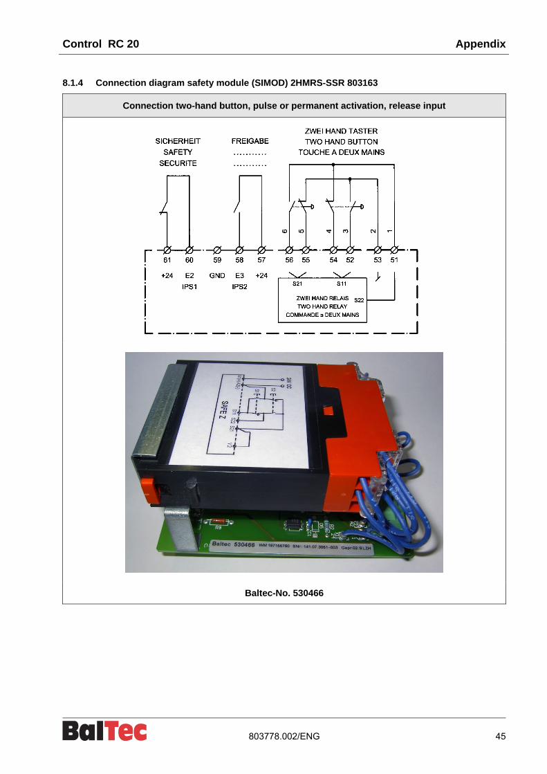
8.1.4 Connection diagram safety module (SIMOD) 2HMRS-SSR 803163
Connection two-hand button, pulse or permanent activation, release input
Baltec-No. 530466
Appendix Control RC 20
46 803778.002/ENG
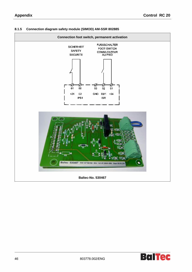
8.1.5 Connection diagram safety module (SIMOD) AM-SSR 802885
Connection foot switch, permanent activation
Baltec-No. 530467

Control RC 20 Appendix
803778.002/ENG 47
8.1.6 Connection diagram safety module (SIMOD) AMS-SSR 802887-a
Connection foot switch, pulse or permanent activation, release input
Baltec-No. 530468

Appendix Control RC 20
48 803778.002/ENG
8.1.7 Wiring diagram contactor module RN pneumatic 802908

Control RC 20 Appendix
803778.002/ENG 49
8.2 Spare parts lists
8.2.1 Control unit RC 20, 814337-n

Appendix Control RC 20
50 803778.002/ENG
Pos. No. Spare name Art. No. Remarks
1 1 Basic unit 530354 120/230/400/440V
3 4 Shock absorber 391202
4 4 Screw 341010 M4x10
9 1 Power supply unit incl. transformer 530355 200/345/480/575V
10 1 Contactor module 530356
11 1 Contactor module 530357
12 1 Contactor module 530358
13 1 Contactor module 530359
14 1 Safety module for permanent activation with foot switch
530467 SIMOD AM-SSR
15 1 Safety module for pulse or permanent activation with foot switch, release input
530468 SIMOD AMS-SSR
16 1 Safety module for for permanent activation with two-hand button
530465 SIMOD 2HMR-SSR
17 1 Safety module for pulse or permanent activation with two-hand button, release input
530466 SIMOD 2HMRS-SSR
19 1 Modification kit 570508 only RNE/RNS 481
20 1 Programmable control 530373 ALB 1761-L16 BWB
21 1 Proportional Valve Driver 530374
22 1 Relay module 534081
23 1 Additional relay 534087
24 2 Distance bolt 530397 M4x60mm DIA SW6
25 3 Screw 346090 M3x6
26 1 Control cable 521078 XY 4x0.75mm2
27 1 Pieces set 530460 RNR with rotary indexing unit MADER
31 Screwed cable gland 525795 M16x1.5 4.0-8.0mm
33 Screwed cable gland 525794 M20x1.5 5.5-12.0mm

Control RC 20 Appendix
803778.002/ENG 51
Pos. No. Spare name Art. No. Remarks
36 Locking plug 371520 M16x1.5 K 295 No.149
37 Locking plug 371521 M20x1.5 K 295 No.188
40 1 Cable machine 520168 3-phase
41 1 Cable machine 520167 1-phase without USA
42 1 Tube fitting straight 525746 CSA, PA-GOB-12M20 NW12-M20x1.5 (Canada)
43 1 Tube fitting with 90° bow angle 525747 CSA, VP-BRB-12M20 NW12-M20x1.5 (Canada)
44 1 Lock nut 525748 CSA. 50.220 PA/SW M20x1.5 (Canada)
45 1 Cable 520230 Bridge
50 1 Thermal relay 524233 Type T16-1.3
51.1 1 Thermal relay 524234 Type T16-1.7
51.2 1 Thermal relay 524235 Type T16-2.3
52.1 1 Thermal relay 524236 Type T16-3.1
52.2 1 Thermal relay 524237 Type T16-4.2
53 1 Thermal relay 524238 Type T16-5.7
54.1 1 Thermal relay 524239 Type T16-7.6
54.2 1 Thermal relay 524240 Type T16-10
55 1 Thermal relay 524241 Type T16-13
60 1 Front cover 814080 optional
101 Power supply unit 530371 120/230/400/440V
102 Transformer 548079 120/230/400/440V
103 Transformer 548080 200/345/480/575V
104 Front unit complete 530367
108 Main switch 522043 SNT A3-8E
109 Contactor 24V, 4kW 533222
KM1 = Riveting motor
KM2 = Hydraulic aggregate motor
KM3 = Second riveting motor (double riveting machines)
110 Relay 534080 24V Type 4KW
111 Control module 530481 PROMOD
112 Rotary knob to main switch 522102 Pos. 108

Appendix Control RC 20
52 803778.002/ENG
Manufacturer
Baltec Maschinenbau AG Obermattstrasse 65 CH-8330 Pfäffikon ZH Schweiz
Tel.: 0041 (0)44 953 13 33 Fax: 0041 (0)44 953 13 44 [email protected] www.baltec.com
Representatives list
Ägypten Finnland Rumänien, Russland
UTP Group Ltd. 5, lbn El Nabih Street Zamalek, Cairo Egypt
Tel.: 0020 2 736 05 34 Fax: 0020 2 736 33 53 [email protected]
C Lindholm Engineering OY P.O. Box 66 Santalantie 25 FI-10901 Hanko-Hangö Finland
Tel.: 00358 207 519 600 Fax: 00358 207 519 619 [email protected] www.clegroup.fi
ALFLETH ENGINEERING AG Hardstrasse 4 CH-5600 Lenzburg Switzerland
Tel.: 0041 (062) 888 70 00 Fax: 0041 (062) 888 70 10 [email protected] www.alfleth.com
Australien Frankreich Schweden
Bliss & Reels Co. Pty. Ltd. 9 Kim Close P.O. Box 215 Bulleen, Victoria 3105 Australia
Tel.: 0061 39 850 6666 Fax: 0061 39 852 1345 www.blissandreels.com.au
BalTec France 11, rue Gustave Madiot ZA les Bordes FR-91070 Bondoufle France
Tel.: 0033 1 69 47 12 00 Mobil: 0033 688 84 8860 Fax: 0033 1 69 47 13 49 [email protected] www.baltec.fr
Colly Company AB Rasebotgsgatan 9 SE-16406 Kista Schweden
Tel.: 0046 8 703 02 57 Fax: 0046 8 703 98 41 Mobil: 0046 70 520 25 05 [email protected]
Australien Grossbritannien, Irland Schweiz
ALLTEC SOLUTIONS 29 Cosgrove street P.O.Box 164 Vermont Vic. 3133 Australia
Tel.: 0061 39 872 6030 Fax: 0061 39 872 6652 Mobil: 0061 418 331 463 [email protected]
BalTec (UK) Ltd. BalTec House, Danehill Lower Earley Reading, Berkshire RG6 4UT, Great Britain
Tel.: 0044 1189 311 191 Fax: 0044 1189 311 103 [email protected] [email protected] www.baltecuk.com
Baltec Maschinenbau AG Obermattstrasse 65 CH-8330 Pfäffikon ZH Schweiz
Tel.: 0041 (0)44 953 13 33 Fax: 0041 (0)44 953 13 44 [email protected] www.baltec.com
BeNeLux Indien Singapore
Heesen-ICA B.V. Afrikalaan 14 A NL-5232 BD's-Hertogenbosch Niederlande
Tel.: 0031 73 641 7365 Fax: 0031 73 642 5735 [email protected] www.heesen-ica.nl
Francis Klein & Co. Private Ltd. 70/1, Mission Road Bangalore - 560 027 India
Tel.: 0091 80 2227 2781 0091 80 2227 2782 Fax: 0091 80 2227 6324 [email protected]
Naka Liquid Control Pte. Ltd 50 Bukit Batok Street 23 #04-11 Midview Building Singapore 659578
Tel.: 0065 6268 5911 Fax: 0065 6268 2170 [email protected]
Brasilien Iran Slowakei, Tschechien
ZELLO Terc.Serv Representaçoes s/s Ltda Av. Samuel Martins 27 s. 112 VI. Progresso 13202-251 – Jundiai SP Brasil
Tel.: 0055 11 9657 8485 0055 11 3964 6617 Fax: 0055 11 4584 7497 [email protected] www.zello-tsr.com.br
Nojand Co. No. 26, ghaffari Ave. hafte - tir square, P.O. Box 15875-4957 Tehran Iran
Tel.: 0098 21 8884 14 77 0098 21 8884 14 78 Fax: 0098 21 8882 53 08 [email protected]
OK Strojservis, s.r.o. Na Kasárnách 152 CZ 396 01 Humpolec Tschechien
Tel.: 00420 604 311 822 Fax. 00420 257 181 056 [email protected] www.ok-strojservis.cz
Bulgarien Italien Slowenien, Kroatien
ALFLETH ENGINEERING AG Hardstrasse 4 CH-5600 Lenzburg Switzerland
Tel.: 0041 (062) 888 70 00 Fax: 0041 (062) 888 70 10 [email protected] www.alfleth.com
Camar S.p.A. Via Genova, 58/A IT-10090 Cascine Vica – Rivoli (TO) Italy
Tel.: 0039 011 959 1626 0039 011 959 2970 Fax: 0039 011 959 4101 [email protected] www.camarspa.it
INTERMER d.o.o. Peruzzijeva ulica 127g Sl-1000 Ljubljana Slowenien
Tel.: 00386 1 280 86 83 Mobil: 00386 41 676 583 Mobil: 00386 41 793 073 Fax: 00386 1 280 86 89 [email protected]
China Japan Spanien
SWISSTEC Shanghai Office Room 1806, Kuen Yang Plaza No. 798 Zhao Jia Bang Road 200030 Shanghai China
Tel.: 0086 21 641 51 105 Fax: 0086 21 641 51 106 [email protected]
Naka Seiki Co. Ltd 2-17, 1-Chome, Kinda-cho Moriguchi, Osaka 570-0011 Japan
Tel.: 0081 6 6901 1875 Fax: 0081 6 6905 8241 [email protected] www.nakaseiki.co.jp
EUROMAQUINA, S.L. Av. De los Pirineos 7, Nave 5A 28703 S. Sebastian de los Reyes (Madrid) Spain
Tel.: 0034 91 658 72 60 Fax: 0034 91 658 62 08 [email protected] [email protected]
China Kolumbien Südafrika
SWISSTEC Beijing Hua Qiao Gong Yu 2-43 Hua Yuan Cun, Xi Jiao 100044 Beijing China
Tel.: 0086 10 684 18 447 Fax: 0086 10 684 12 869 [email protected]
Imocom S.A. Apartado Aéreo 12287 Santafé de Bogotá Colombia
Tel.: 0057 1 262 3800 Fax: 0057 1 262 4982 [email protected] www.imocom.com.co
Edwin Roth (Pty.) Ltd. P.O. Box 1756 6 Derrick Road, Spartan Kempton Park Johannesburg South Africa
Tel.: 0027 11 970 1930 /1/2/3 Fax: 0027 11 394 1132 [email protected]
Dänemark Korea Türkei
Sneholt & Nilsen A/S Adalen 9 DK-4600 Koge Denmark
Tel.: 0045 4615 4600 Fax: 0045 4615 4225 [email protected] www.sneholt-nilsen.dk
Dongso P.A. Co., Ltd. Dongso-Bldg. #394-7 Hapjeong-Dong, Mapo-Ku, Seoul Korea 121-886
Tel.: 0082 2 338 0770 Fax: 0082 2 338 8496 [email protected] [email protected]
ÇAG-KAR DIS TICARET MÜMESSILLIK Yunus Emre Mah. Veysel Karani Cad. No.143/C SANCAKTEPE TR-34791 ISTANBUL, Turkey
Tel.: 0090 216 430 89 29 Mobil: 0090 542 671 36 19 Fax: 0090 216 430 90 09 [email protected] [email protected] www.turkticaret.net/cag-kar
Deutschland PLZ: 6, 7, 8, 94 (ausser 83) Malaysia, Philippinen Ungarn
BalTec Maschinenbau AG Home-Office Am Bahndamm 18/1 DE-73342 Bad Ditzenbach Deutschland
Tel: 0049 7335 923 412 Fax: 0049 7335 923 3069 Mobil: 0049 175 1816 132 [email protected]
Naka Liquid Control Co. Ltd 50 Bukit Batok Street 23 #04-11 Midview Building Singapore 659578
Tel.: 0065 6268 5911 Fax: 0065 6268 2170 [email protected]
ALFLETH ENGINEERING AG Hardstrasse 4 CH-5600 Lenzburg Switzerland
Tel.: 0041 (062) 888 70 00 Fax: 0041 (062) 888 70 10 [email protected] www.alfleth.com
Deutschland PLZ: 0, 1, 2, 39, 9 (ausser 94) Oesterreich, Deutschland PLZ: 83 USA, Kanada; Mexico
BalTec Maschinenbau AG Home-Office Holzacker 8 DE-96253 Untersiemau Deutschland
Tel.: 0049 9565 610 790 Mobil: 0049 175 406 83 42 Fax: 0049 9565 610 787 [email protected]
HAMOTEK Montagetechnik GmbH Grödiger Strasse 10 AT-5081 Anif Oesterreich
Tel.: 0043 6246 72788 Mobil: 0043 664 3420959 Fax: 0043 6246 72980 [email protected] www.hamotek.at
BalTec Corporation 130 Technology Drive Canonsburg, PA 15317 USA
Tel.: 001 724 873 5757 Fax: 001 724 873 5858 [email protected] www.baltecorporation.com
Deutschland PLZ: 3 (ausser 39), 4, 5 Polen
Technisches Büro Diehl GmbH Hofstrasse 137 Postfach 231 DE-40723 Hilden Deutschland
Tel.: 0049 2103 614 43 Fax: 0049 2103 22 546 [email protected] [email protected] www.tb-diehl.de
Julmar ul. Lopuszanka 53 PL-02-232 Warszawa Polen
Tel.: 0048 22 629 25 63 Mobil: 0048 601 221 409 Fax: 0048 22 625 45 54 [email protected]

Control RC 20 Index
803778.002/ENG 53
9 Index
A
Abbreviations .............................................................. 14
Adjusting monitoring time in setup (Initiator lower end position) .................................................................. 39
Auto-cycle operating mode ......................................... 22
B
Bridging initiator .......................................................... 37
C
Change over from operation with two-hand operating unit to operation with foot switch ............................ 40
Changing setup parameters ....................................... 28
Coding system for the individual setup parameter sectors .................................................................... 27
Control functions / Terms ............................................ 11
Control unit maintenance ............................................ 41
D
Details RC 20 control unit ............................................. 9
Diagnosis menu .......................................................... 32
Dimensions drawing RC 20 control unit ...................... 10
E
Electric supply ............................................................ 15
Error ............................................................................ 33
G
General errors ............................................................ 36
H
History menu .............................................................. 32
I
Info menu (Page 1) ..................................................... 24
Info menu (Page 2) ..................................................... 25
Information and symbols ............................................... 6
Initial commissioning ................................................... 16
Initiation monitoring ..................................................... 13
Initiator lower end position .......................................... 37
K
Key switch .................................................................. 40
L
List of error messages <ERR> ................................... 34
List of messages <MES> ............................................ 33
M
Machine not ready for operation ................................. 18
Machine ready for operation ....................................... 18
Main menu RC 20/RC 20A ......................................... 19
Messages ................................................................... 33
Miscellaneous menu ................................................... 32
MMI ............................................................................... 9
O
Operation of the riveting spindle ................................. 11
Operation of the spindle motor .................................... 11
Original language of assembly instructions ................... 5
Q
Questions or unclear points .......................................... 5
R
Rivet initiation.............................................................. 12
Riveting actuation ....................................................... 12
Riveting initiation principle drawing ............................. 13
Riveting procedure (RP) ............................................. 11
Riveting time (RT) ....................................................... 11
S
Safety circuit ............................................................... 12
Safety measures ........................................................... 7
Safety module SIMOD ................................................ 12
Schemata .................................................................... 42
Setup menu ................................................................ 27
Setup operating mode ................................................. 20
Setup Table, SW-Version 2.05 A and 2.05 B .............. 29
Single cycle operating mode ....................................... 21
Spare parts lists .......................................................... 49
Start-up ....................................................................... 18
Superordinate PLC control .......................................... 17
Switching on the control unit ....................................... 18
Switching status monitoring (Initiator lower end position) ............................................................................... 38
Symbols ...................................................................... 14
T
Technical specifications RC 20 control unit ................ 10
Tools menu ................................................................. 26
Troubleshooting and error rectification ........................ 33
W
Warning and safety notices ........................................... 6

Index Control RC 20
54 803778.002/ENG