control principles rev d
TRANSCRIPT
technical guide control principles
Philips Dynalite Technical Guide – Control Principles Page 1 of 11
overview
This document outlines the structure and principles employed in a Philips Dynalite control system,
including information on DyNet network architecture, operating concepts, system commands, device
addressing and other associated features.
system structure
The Philips Dynalite system utilises a true distributed processing architecture, where a range of devices
are interconnected over an RS485 network to form a complete control solution. All commands and
status information is passed to all devices over this network using the event based DyNet protocol. All
Philips Dynalite control devices incorporate an integral microprocessor and internal non-volatile
memory. This allows for each device to store its own configuration data and possessing requirements to
perform the required features and functions, meeting the project requirements. All device
configurations are configured through the use of EnvisionProject, Philips Dynalite‟s commissioning,
monitoring and control software, used to bring the individual devices together to form a system solution
for projects needs.
Philips Dynalite‟s distribution of intelligent devices architecture, dramatically improves reliability over
systems that incorporate centralised processors, where malfunction of one device could result in total
system failure. Should a single device fail in a Philips Dynalite system, all other devices will continue to
operate as normal. This distributed architecture also supports a wide range of interfaces, manufactured
by Philips Dynalite and other system vendors, to offer a robust flexible approach to control of lighting
and other automation systems found in modern projects.
Philips Dynalite‟s range of control products can be broadly categorised as a relationship between; User
Interfaces, Integration devices and Load Controllers. The user interface range includes many different
user control panels, LCD touchscreens, timer clocks, computer head-end software and sensors. User
interfaces are generally programmed to trigger single command messages onto the DyNet network, in
response to a user or input action. Integration devices have been developed to allow other third-party
systems that are commonly found within projects to control the Philips Dynalite system or vice versa.
This allows many systems to work together achieving a required task and reducing the need for the end-
user to interact with each individual system. Philips Dynalite has developed an extensive range of
controllers with a variety of output types, combinations and load ratings. Load controllers constantly
listen to the network messages from Dynet and only respond to command messages that relate to the
controller‟s specific addressing configuration. Control associations are established between user
interfaces, integration devices and load controllers using straightforward addressing and command
techniques with in the Dynet protocol.

Page 2 of 11 Philips Dynalite Technical Guide – Control Principles
device addressing
physical
Each Philips Dynalite load controller on the Dynet network can be identified as a device type and a box
number. With this information the different devices on single networks can be individually addressed for
commissioning. All physical control channels within the load controllers of a Philips Dynalite system have
a Physical and Logical Address. Physical addresses are used within the load controllers and refer to the
physical control channel within a device. This is primarily used during system commissioning to configure
devices as they can be used to identify the individual channels. To identify an individual circuit
connected to a load controller, a Device Type, Box Number and Physical channel number are used by the
commissioning software Envision. The term Physical refers to the individual physical attributes of the
control point. For example a 12 Channel load controller could be addressed as Box 1 and will always
have 12 Physical Channels. These Channels are physically different from the Channels in 12 Channel load
controller Box 2. Physical addresses are also used for reporting system diagnostic information related to
hardware operation.
Similarly for a user interface panel, a Device Type, Box Number and Physical button number are used for
addressing the different input options. Physical addressing is also used to obtain operating parameter
variables from specific devices. An example of this is a technique that can be adopted with a sensor.
Sensors are normally configured to directly issue commands when particular lighting levels are reached
or movement is detected. However, in certain projects it may be necessary to create separate control
routines external from the sensor based on the lighting level sensed or occupancy status detected. This
can be achieved by directly addressing the sensor with physical messages, thus bypassing the device
configuration. This type of message could directly query the sensor for status information of occupancy.
This feature is typically used when a monitoring system is added to the Philips Dynalite installation such
as airconditioning control systems.
logical
Load controller output channels and user control panel buttons are generally configured to logical Areas,
independent of their physical characteristics i.e. the device they are connected to. This logical overlay
enables control points to be grouped regardless of their physical association. A Logical Channel is a
nominated Physical Channel that is assigned to an Area. Multiple physical channels in different load
controllers can be grouped together into logical areas for network addressing requirements. This allows
the Dynet network to control many different physical channels with one network message. The Philips
Dynalite system can support up to 65,535 Areas and each Area up to 65,535 Logical Channels. It is also
possible to assign more than one Physical Channel to a single Logical area. In a lighting control
application, consider the scenario of a large room with 9 Physical Channels driving downlights along the
length of the wall. All of these Physical Channels can be assigned to just one Logical area. This
simplifies operation of large installations, as the end-user only has to make adjustments to one channel.

Philips Dynalite Technical Guide – Control Principles Page 3 of 11
The Philips Dynalite system can be divided into smaller subsections using logical addressing. Consider
the example of a dimmer that supplies lighting circuits to two rooms, with a user control panel in each
room. The controller lighting circuits and the control plate in Room 1 would be configured as Area 2,
and the controller lighting circuits and the control plate in Room 2 would be configured as Area 3. The
end result would be that the control plate set to Area 2 would only control or program circuits
designated Area 2 and the control plate set to Area 3 would only control or program circuits designated
Area 3, so the two rooms will operate independently of each other.
Area 2
Office 1
Logical
Channel 1 CP1 CP2
Load
(Outputs)
1 Phase 40A
DLE410
CH1
CH2
CH3
CH4
Logical
Channel 2
Area 3
Office 2
Logical
Channel 1
Logical
Channel 2
The ability to logically bind individual control channels into groups is essential in installations involving a
large number of channels. Without this facility it would not be practical to view and configure the
control channels within a project as they would need to be addressed individually. Configuration and
maintenance of systems that do not allow for physical channels to be grouped into logical areas can
therefore become quite cumbersome and time consuming to configure or edit requested changes.
preset states
During commissioning each Philips Dynalite load controller may be configured with a number of output
states, which are referred to as Presets. Most load controllers will typically accommodate up to 170
presets. The preset defines a specific output level for each channel of the controller.
Scene 1 Scene 2 Scene 3 Scene 4OFF1
2
3
4 Prog
The illustration above is a typical lighting control application where different intensities of the lighting
are required for each of the four channels. These are set and stored in the controller‟s memory during
commissioning. It is then possible to “recall” these settings from the controller‟s memory from a single
Page 4 of 11 Philips Dynalite Technical Guide – Control Principles
network message at the touch of a button or at predetermined times, from a timer clock or
automatically from an integrated building management system.
A typical application for this approach would be in a hotel coffee shop, where the proprietor requires a
pre-determined lighting “scene” for breakfast, another for lunch, one for dinner and another for
suppertime. These settings can be preset and then simply recalled at the touch of a button. The time
for the change to fade from one scene to another may also be preset and stored in memory. This way
the patrons do not feel any visual discomfort when the lighting changes from one mood to another over,
say, 10 minutes and all the lighting channels will change at the same time.
operating concepts
The Philips Dynalite system can be controlled in several different ways, dependent on application
requirements. Output changes can be achieved using Area Preset or Channel Level command messages.
The most common approach is Area Preset control where Preset states stored within the controller are
recalled. Area Preset command messages will affect all control points that are assigned to the
respective message Area. An example of this would be a button press on a user control panel that is
configured to issue an Area Preset command, say Area 1 go to Preset 1 over 5 seconds. All load
controllers with channels assigned to Area 1 would change from their current preset to preset 1 output
state in five seconds. Status indicators on all user control panels with buttons assigned to Area 1 Preset
1 will also follow accordingly. This network interaction of all devices responding to the same message
allows for simpler commissioning as only one network message is needed to instigate changes in multiple
devices, either load controllers or user interfaces. Preset control is ideally suited to applications where a
large number of channels are to be controlled in a single area.
The ability to recall a preset scene affecting multiple load channels in one area with a single network
message is critical in architectural lighting applications. Systems that do not include provision to store
presets or require multiple network messages to achieve a state or scene change may produce a
discernable cascade effect as the channels sequentially receive individual level commands. This often
produces an undesirable „mexican-wave‟ effect and network traffic complications.
If required, channel Level command messages can also be used to affect output change on a specific
Channel within a defined Area. An example of this would be a user control panel button configured to
issue the message Area 1 Channel 1 go to 50% over 5 seconds. All load controller channels assigned to
Area 1 Channel 1 would go to 50% output in 5 seconds. This method can be used where individual
channel control is required and the number of channels is low. It is typically used in a home or small
office environments where the user wishes to manually change the load controller output levels.
Philips Dynalite Technical Guide – Control Principles Page 5 of 11
programmable logic control
All Philips Dynalite user interface devices also incorporate programmable logic control functionality.
Using Envision software it is possible to author and embed complex programs within these devices that
use arithmetic, sequential and conditional logic functions. These programs are referred to as tasks.
Tasks can be triggered from within a device or from another device on the same network.
Tasks are often used in applications where a single input or user interface action is required to deliver
control over multiple areas. An example in architectural lighting applications would be a “welcome”
function on a user control panel located at an entry point to a residence or office. When operated, the
task issues a sequence of area preset commands required to illuminate an access path through the
installation.
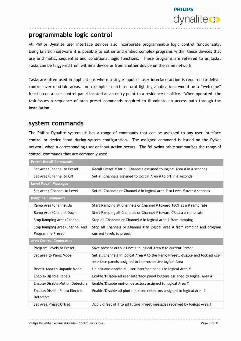
system commands
The Philips Dynalite system utilises a range of commands that can be assigned to any user interface
control or device input during system configuration. The assigned command is issued on the DyNet
network when a corresponding user or input action occurs. The following table summarises the range of
control commands that are commonly used.
Preset Recall Commands
Set Area/Channel to Preset Recall Preset # for all Channels assigned to logical Area # in # seconds
Set Area/Channel to Off Set all Channels assigned to logical Area # to off in # seconds
Level Recall Messages
Set Area/ Channel to Level Set all Channels or Channel # in logical Area # to Level # over # seconds
Ramping Commands
Ramp Area/Channel Up Start Ramping all Channels or Channel # toward 100% at a # ramp rate
Ramp Area/Channel Down Start Ramping all Channels or Channel # toward 0% at a # ramp rate
Stop Ramping Area/Channel Stop all Channels or Channel # in logical Area # from ramping
Stop Ramping Area/Channel And
Programme Preset
Stop all Channels or Channel # in logical Area # from ramping and program
current levels to preset
Area Control Commands
Program Levels to Preset Save present output Levels in logical Area # to current Preset
Set area to Panic Mode Set all channels in logical Area # to the Panic Preset, disable and lock all user
interface panels assigned to the respective logical Area
Revert Area to Unpanic Mode Unlock and enable all user interface panels in logical Area #
Enable/Disable Panels Enable/Disable all user interface panel buttons assigned to logical Area #
Enable/Disable Motion Detectors Enable/Disable motion detectors assigned to logical Area #
Enable/Disable Photo Electric
Detectors
Enable/Disable all photo electric detectors assigned to logical Area #
Set Area Preset Offset Apply offset of # to all future Preset messages received by logical Area #

Page 6 of 11 Philips Dynalite Technical Guide – Control Principles
Set/Clear Area Links Set/ Clear area links between channels assigned to logical Area #
Status Commands
Area Status
Request/Reply Current Preset Request current Preset in logical Area #. System replies with current Preset #
for respective logical Area #.
Request/Reply Current Area Link
State
Request current area links between channels assigned to logical Area #
Channel Status
Request/Reply Channel Level Request current Channel Level # for logical Channel # in logical Area #.
System replies with current Channel Level # for respective logical Channel #
in respective logical Area #
The Philips Dynalite system supports many commands beyond those outlined above. Further details are
available on request.
global functions
It is possible to send every area on a network to a single Preset using Area 0 (zero) as the addressed
Area. There are implications when adopting this method where different third-party devices are in use
such as curtains etc. For this reason Preset messages to specified Areas are the preferred method of
global control.
combining control spaces
Applications where de-mountable partitions or removable walls are being used (typically in areas such as
hotel ballrooms, training rooms and conference centres) will require the control system to combine and
separate lighting groups. It is usual that each space has its own user control panel. When the partitions
are opened or closed, thus dividing a room, it is most important that the control system for the lighting
should also combine or segregate in harmony with the partition status. In practice this means that when
a room is divided, the control panel in one section must not be able to control the lighting in another
section. However, as soon as the partition is opened, both control panels should work in parallel. This
completely automates the room-combining function, so the user does not have to worry about
configuring the system to suit the current arrangement. Philips Dynalite‟s supports Join or Area Link
functions can be used to combine or separate control groups in these applications.
The Join function is suitable for applications where there are a small number of separate sections
involved. The Join function enables an Area to be divided into a number of sub sections. Sub sections
can be combined and separated using the appropriate Join command. Area linking should be used in
applications involving a large number of sections. This function modifies the load controllers to
temporarily assign channels to more than one Area. With area linking, it is possible to create temporary
control links between a total of 24 independent Areas with two-way control from each panel within the
area that is being linked. The obvious main difference between this method and Join is the ability of

Philips Dynalite Technical Guide – Control Principles Page 7 of 11
area link to combine a greater number of areas to work together as one larger area.
A dedicated Base Link Area can also be used to act as a global area for Channels assigned to that Base
Link Area and is useful as a global control for a block of Areas. The channels to be controlled are
assigned during commissioning and can be in one of the 24 areas above the dedicated Base Link Area.
Area linking is uni-directional, so if areas 7 and 10 for example, are to work in tandem there must be
two area link messages sent; one message to link area 7 to area 10 and one message to link area 10 to
area 7.
In the example below areas 7-12 are all independent areas that can be controlled with standard preset
messages. Assigning them to base link area 6 means that if and when required, any of the six areas
shown can be linked to any of the other areas causing it to listen to another area‟s messages as well as
its own. It could be possible; for example, if all areas indicated by base link area 6 were to be used
together for a function, all the areas could be linked and controlled together with a single DyNet
message.
Area 7
Area 8
Area 9
Area 10
Area 11Area 12
Area 2
Area 3
Area 4
Area 5
Area 14
Area 13
Base
Area 6
Area linking can also be used to provide a pseudo global Area other than Area 0. It is possible to create
a pathway of light through a number of different areas by sending a single control message to the base
link area.
network watchdog
Fail safe operation of the Philips Dynalite system can be maintained through the Network Watchdog
feature. This involves broadcasting a special data packet (the Watchdog Tick) to all load controllers
across the network at programmed intervals. If a particular controller does not receive these messages
within a predefined period, the controller will default to an assigned panic preset or to a specific preset
stored in the load controller. This ensures that all controllers revert to a safe operating state should any
part of the network cabling be physically severed, or there is a load controller failure.

Page 8 of 11 Philips Dynalite Technical Guide – Control Principles
status indicator tracking
All user control panels incorporate LED status indicators on all buttons that can be used to indicate the
current preset state of an Area. When a Preset message is transmitted on the network, any indicators
will illuminate on any user control panel button that is also assigned to that Area Preset automatically
and without the need for additional network messages. Indicators for buttons assigned to other presets
within the same Area will turn off. In this way the panels will always indicate the current state of an
area.
In some circumstances it may be necessary to change the state of some or all button status indicators on
a user control panel. The Philips Dynalite system enables status indicators to be controlled
independently using an appropriate physical command message. It is also possible to change the state of
specific button status indicators while leaving others in their current state.
diagnostic functions
The Philips Dynalite system also supports a number of advanced diagnostic functions, which include
Device Online/Offline status, Circuit Breaker Trip Reporting and Circuit Run Time Tracking.
Device Online/Offline status enables all devices to be periodically polled to determine if they are visible
on the network and operating normally. Invoking this function in Envision software ensures that network
or device failures are identified promptly.
Load controllers that incorporate the Circuit Breaker Trip reporting function will broadcast a message on
the DyNet network when a load circuit breaker on the controller trips. The message identifies the
Physical device and channel affected by the tripped circuit breaker. These messages can be used to
alert maintenance personnel of faults so that remedial action can be promptly carried out.
Controllers that support Circuit Run Time tracking will continuously record the accumulated operating
time for each output channel. Run time data for each controller can be queried or reset at any time.
This information can be used by a site management system for scheduling periodic maintenance, such as
lamp replacement intervals on lighting fixtures.
the physical network
Philips Dynalite systems utilise RS485 as its physical network, which is an industry standard method of
data transmission as detailed in the TIA/EIA-485-A specification, with some variations. (For more
information on the TIA/EIA-485-A specification: www.tiaonline.org)
The TIA/EIA-485-A specification defines a UL (Unit Load), which declares that an RS485 driver must be
able to drive 32 ULs. This means that an RS485 network supports 32 nodes, when each node bears a unit

Philips Dynalite Technical Guide – Control Principles Page 9 of 11
load on the line. Philips Dynalite products use 1/8 UL drivers and we recommend up to 128 devices on a
network segment.
Another important variation from the TIA/EIA-485-A specification is the addition of an extra conductor
that carries a DC supply, which is generated by an integral power supply contained within all mains
powered load control devices which is used to energise network devices that are not connect to mains
power, such as motion detectors, wall mounted control panels and timer clocks.
Figure 1: Typical small DyNet Network
Devices are simply connected with a general purpose 3 twisted pair and shield data cable that loops
around to all devices as depicted in Figure 1. If using CAT5 cable the 4th pair can be left as a spare or
used as a drain wire. The connections are as follows:
Note the conductors that carry the DC supply are both wires in the pair paralleled. This
is to avoid the DC supply suffering voltage drop on long cable runs. A 5-way pressure
pad terminal strip is provided on devices for data cable termination. All devices also
have RJ12 connector for temporary connection for commissioning. Some DIN rail load
controllers support two RJ12 connectors for faster termination within the distribution
board.
Terminal Cable Recommended Colour Coding
Shield Drain wire (or CAT5 spare pair) Shield (or Brown pair)
GND 1 pair paralleled Green pair
D+ ½ pair Blue
D- ½ pair Blue / White
+12V 1 pair paralleled Orange pair

Page 10 of 11 Philips Dynalite Technical Guide – Control Principles
Some sites require far more devices than the 128 maximum allowed on a single network. A typical
application is a multi story building, with each floor containing a network of devices. The network
segment for each floor is called a Spur. All spurs are joined together via a Trunk, which is quite often
installed in a riser, linking all floors together.
Larger DyNet Network utilising trunk & spur technology
Each of the floors can run an independent sub-network that does not require any input from other
devices. With each of the floor sub-networks being connected together by bridges on the trunk site-wide
network messages can be sent that will affect the whole project, allowing the entire system to work
together as one. Typically the Trunk is where computer head-end software or BMS will be connected so
there is full access to all the required components of the network.
Note the spurs do not directly connect to the trunk, but are connected via Network Bridges. A Network
Bridge has two RS485 ports that are optically isolated from each other, which will assist to isolate any
faults to a single spur only and also provide galvanic isolation. The use of Network Bridges allows the
maximum number of devices on a single network to be 16,776,960. Network Bridges may also be used as
repeaters when cable runs exceed 1,000 metres. In addition to optical isolation, the Network Bridge can
also be configured as a network filter for stopping unrelated messages being transmitted onto irrelevant
sections of the network, therefore reducing the number of network messages. The Gateways can also be
used to run task on a floor so that when it receives a message from the truck requesting the system

Philips Dynalite Technical Guide – Control Principles Page 11 of 11
change to “After hours” mode, the gateway can then send out the required messages on the sub-floor
network to comply.
dynet 2 protocol properties
Packet Length: Variable, 12 to 1024 bytes
Integrity Checking: 16 bit Fletcher Checksum
Baudrate: 9600 baud to 460800 baud (device dependant)
Data Word Format: 8 bit data, 1 start bit, 1 stop bit, no parity (8N1)
Message Tracking: Source network address embedded in each packet
Logical Areas: 65534, 0 = All Areas
Logical Presets per Area: 65519 editable, 16 predefined
Logical Channels per Area 65534, 0 = All Channels
Fade times per message: 0 to 23.3 hours @ 100mS resolution
Physical Channels per device: 65534, 0 = All Channels
Physical Device Types: 254
Physical Box Numbers per Device Type: 65535
2011 Dynalite Intelligent Light Pty Limited (ABN 97 095 929 829). All rights reserved. Not to be reproduced without permission. Dynalite, DyNet, DLight and associated logos are the registered trademarks of Dynalite Intelligent Light Pty Ltd.