control of x-y table using siemens plc
TRANSCRIPT

UNIVERSITI TEKNIKAL MALAYSIA MELAKA
Control of X-Y Table Using Siemens PLC
Thesis submitted in accordance with the requirements of Universiti Teknikal
Malaysia Melaka for the Bachelor of Manufacturing Engineering (Robotic &
Automation)
By
Suria Azlin binti Ismail
Faculty of Manufacturing Engineering
May 2007

JUDUL: CONTROL OF X-Y TABLE USING SIEMENS PLC
SESI PENGAJIAN: 2/2006-2007 Saya SURIA AZLIN BINTI ISMAIL mengaku membenarkan tesis (PSM/Sarjana/Doktor Falsafah) ini disimpan di Perpustakaan Universiti Teknikal Malaysia melaka (UTeM) dengan syarat-syarat kegunaan seperti berikut:
1. Tesis adalah hak milik Kolej Universiti Teknikal Kebangsaan Malaysia. 2. Perpustakaan Kolej Universiti Teknikal Kebangsaan Malaysia dibenarkan
membuat salinan untuk tujuan pengajian sahaja. 3. Perpustakaan dibenarkan membuat salinan tesis ini sebagai bahan pertukaran
antara institusi pengajian tinggi. 4. **Sila tandakan (√)
KUTKM Library (Pind.1/2005)
SULIT
√
TERHAD
TIDAK TERHAD
(Mengandungi maklumat yang berdarjah keselamatan atau kepentingan Malaysia yang termaktub di dalam AKTA RAHSIA RASMI 1972)
(Mengandungi maklumat TERHAD yang telah ditentukan oleh organisasi/badan di mana penyelidikan dijalankan)
Disahkan oleh:
(TANDATANGAN PENYELIA)
Cop Rasmi:
Tarikh: _______________________ * Tesis dimaksudkan sebagai tesis bagi Ijazah Doktor Falsafah dan Sarjana secara penyelidikan, atau
disertasi bagi pengajian secara kerja kursus dan penyelidikan, atau Laporan Projek Sarjana Muda (PSM). ** Jika tesis ini SULIT atau TERHAD, sila lampirkan surat daripada pihak berkuasa/organisasi berkenaan dengan menyatakan sekali sebab dan tempoh tesis ini perlu dikelaskan sebagai SULIT atau TERHAD.
UNIVERSITI TEKNIKAL MALAYSIA MELAKA Karung Berkunci 1200, Ayer Keroh, 75450 Melaka Tel : 06-233 2421, Faks : 06 233 2414
BORANG PENGESAHAN STATUS TESIS*
UNIVERSITI TEKNIKAL MALAYSIA MELAKA
(TANDATANGAN PENULIS)
Alamat Tetap: NO 201 KOTA GELANGGI 03, 27000 JERANTUT, PAHANG DARUL MAKMUR. Tarikh: _______________________
DECLARATION
I hereby, declared this thesis entitled “Control of X-Y Table Using Siemens PLC” is the
results of my own research except as cited in references.
Signature : …………………………………
Author’s Name : Suria Azlin binti Ismail
Date : ………………………………....

APPROVAL
This thesis submitted to the senate of UTeM and has been accepted as partial fulfillment
of the requirements for the degree of Bachelor of Manufacturing Engineering (Robotic
& Automation). The member of the supervisory committee are as follow:
…………………………………
Main supervisor,
(En. Azrul Azwan bin Abdul Rahman)
Faculty of Manufacturing Engineering
i
ABSTRACT
Programmable logic control (PLC) is the most common automation controller that being
used in industry. It is universally applied for factory automation, process control and
manufacturing systems. The system is originated from the creation of computerized
versions of relay control systems which is used to control machines. There are several
types or models PLC used. Ladder logic is a program method which is used to allow the
sequences of logical actions to be set up, inter-linked and timed. This project being use
SIMATIC S7 as a medium controller for controlling XY table education training kit. The
program will be developing to control positioning axis and functioning switch and
buttoning XY table. Ladder diagram (LD) and function block diagram (FBD) are chosen
as program languages. There are four phase methodology of rapid application
development (RAD) is applied and will be more presses and absorbed in the
methodology flow chart program to ensure the objectives are achieved. The appropriate
instruction control programming of XY table will be recommended as result, then
several suggestion will be recommend from the observation and analysis program
developed closely to the project report.
ii
ABSTRAK
Kebiasaannya, aktiviti perindustrian menggunakan kawalan logik program atau
programmable logic control (PLC) bagi kaedah pengawalan sistem berautomasi
seperti sistem pemprosesan dan pembuatan. Perihal permulaan sistem logik merupakan
ciptaan daripada versi pengganti sistem kawalan pengkomputeran bagi tujuan
pengawalan mesin. Terdapat pelbagai model kawalan logik program digunakan. Tangga
turutan logik atau Ladder logic merupakan kaedah aturan program bagi membenarkan
rangkaian tindakan logik dalam pembinaan struktur program, perhubungan dalaman, dan
pemasaan. Dalam melaksanakan latihan ilmiah ini, Kawalan logic program SIMATIC
S7 digunakan sebagai medium kawalan perlaksaan peralatan latihan pembelajaran XY
table. Program yang akan dibina berfungsi sebagai pengawalan kedudukan paksi dan
butang XY table. Ladder diagram (LD) dan function block diagram (FBD) antara
dua pilihan perantaraan bahasa program. Terdapat empat fasa utama pembinaan program
ditekankan melalui kaedah metodologi, ketangkasan applikasi pembangunan atau rapid
application development (RAD) bagi memastikan pencapaian objektif. Proses program
kawalan XY table akan dibentangkan sebagai keputusan, seterusnya penyusulan
cadangan daripada pemerhatian dan analisis program mengakhiri laporan latihan ilmiah
ini.

iii
DEDICATION
For my beloved family and friends.

iv
ACKNOWLEDGEMENTS
First and foremost I would like to express my sincere gratitude and appreciation to my
supervisor, En. Azrul Azwan b. Abdul Rahman who provided me a lot of ideas on how
to do and success in this final year project. As a principle lecturer at Universiti Teknikal
Malaysia Melaka (UTeM), he has relentlessly showed his supports and intelligence in
helping me to solve my problems during this project is under construction.
Then, not forgetting Pn. Aidawatty who had enthusiastic support of the report revision.
With her help and guidance I’m able to gain better understanding about the project
structure.
I would like to express the profound gratitude to my beloved family for incessant love
and support in undergoing graduate study. They have contributed a lot by their
continuous encouragement and understanding that made this research work possible.
Finally, I’m also happy to present my gratefully acknowledge to anybody who have
helped directly or indirectly in writing this report for their contribution in guidance me
finished this report.

v
TABLE OF CONTENTS
Abstract………………………………………………………………….…..……..…….i
Abstrak ………………………………………………………………..………….……. ii
Dedication……………………………………………………………….……………...iii
Acknowledgement………………………………….…………….…..….…….….…… iv
Table of Contents………………………………………………….………...……..….. ix
List of Tables ………………………………………………………………..………….v
List of Figures ……………………………………………………….………........…. xiii
Sign and Symbols…………………………..………………………………........…... xiv
1. INTRODUCTION……………………..………...…………………………….…....1
1.1 Problem Statements………………….………………………….………………….3
1.2 Objectives…………………………………………………………………………..3
1.3 Scope of Project………………………………...…………………………………. 3
1.4 Project Planning…………………………………………………………………….5
1.5 Project Flow Chart………………………………….………………………………6
1.6 Project Summary……………………………...……………………………………7
2. LITERATURES RIVIEW……………………...…………………...…...........……8
2.1 XY Table………………………………………………….………………….…….8
2.1.1 Component Mechanisms…………………………….……………………….9
2.1.1.1 Mechanical Components……………………………………..…………..10
2.1.1.2 Electrical Components………………………………………...………….15
2.1.2 Control System………………………………………………………...……18
2.1.2.1 Motion Mechanisms...……………………………………...…………….18
2.1.2.2 Loop Systems………………………………………………….…………21
2.1.3 Positioning Coordinate System……………………………………………..25

vi
2.1.3.1 The Cartesian Coordinate System………….………..……...……………25
2.1.3.2 Positive and Negative Movement…………………………...……………27
2.1.3.3 Positioning Program………………………..……………...……..………28
2.1.4 Controller…………………………………….…..………..………….….….30
2.2 Programmable Logic Controller (PLC)………………..………...………………..31
2.2.1 Hardware………………………………………..……………………..……32
2.2.1.1 Mechanical Design of PLC System……………………………..………..34
2.2.2 Internal Architecture……………………………………………….………..36
2.2.2.1 The Central Processor Unit (CPU)……………………………….………38
2.2.2.2 The Buses……………………………………………..……….……….. .38
2.2.2.3 Memory…………………………………………….……….……………39
2.2.2.4 Input Output (I/O)Units…………………………….……..……………. 41
2.2.3 Siemens PLC………………………………………………….…………….43
2.2.4 Programming…………………………………………..….……………….. 44
2.2.4.1 Program Contact Symbols………………………………….…………….45
2.2.4.2 PLC Ladder Programming……………………………….……………….47
2.2.4.3 Functional Block Diagram………………………………………………..54
3. METHODOLOGY……………………………………..…………….……………58
3.1 Project Methodology…………………………………..…….……………………58
3.1.1 Methodology Stage………………………………...….…………………… 59
3.1.1.1 Requirement Planning Phase……………………………..………………59
3.1.1.2 Analysis Phase………………………………………….….….………….59
3.1.1.3 Design Phase……………………………………………….….………….60
3.1.1.4 Implementation Phase……………………………………….……………60
3.1.2 Methodology Flow…………………………………………...……………..61
3.2 Experiment Setup………………………………………………...….……………62
3.2.1 Equipments…………………………..…………………….………………..62

vii
4. RESULT………………….……………………...…….………………….…..........63
4.1 Development…………………………………..…………………………….……63
4.2 Implementation…………………………………….……………..………………65
4.3 Results……………………………………………….………………………..….66
4.3.1 Program One………………………………….…………………………….66
4.3.1.1 Program Network and Description………………………….……..…….66
4.3.2 Program Two………………………………..……………………….…….82
4.3.2.1 Program Network and Description……………………….…….………. 83
5. ANALYSIS & DISCUSSION…………………………………………………….102
5.1 Analysis………………………………………...……………………………….102
5.1.1 Hardware Analysis……………………………………..…………………103
5.1.1.1 XY Table Analysis………………………………….………………….103
5.1.2 Program Analysis…………………………………………….……..…….106
5.1.2.1 Program Task Description and Analysis……………….…...………….106
5.1.2.2 Devices Program Analysis……………………..……...…….………….108
5.1.2.3 Program Structure Analysis …………………………..…….………….111
5.2 Programs Task Discussion…………………………………....…………………114
5.2.1 Program One Description………………………………..…….………….115
5.2.1.1 Problem and Solution…………………………………………………..116
5.2.2 Program Two Description……………………………………..………….118
5.2.2.1 Problem and Solution………………………………………….……… 118
6. CONCLUSIONS AND RECOMMENDATION………………….…..…………120
6.1 Observation Weaknesses and Strengths………………..……………...………..120
6.2 Propositions Improvement……………………………...…………….…….…..121
6.3 Recommendation and Suggestion…………………..………………….……….122
6.4 Project Conclusion…………………………………...……………..……….….122
REFERENCES………………………………………………..……………………...123

viii
APPENDICES…………………………………………………….………………….126
A: Symbol, Address and Comment……………………………………………………126
B: Functional Block Diagram (Program One)………………………….………129
C: Functional Block Diagram (Program Two)…………………………………142
ix
LIST OF FIGURES
1.1 The Various Type of XY Table 2
1.2 Project Flow Chart 6
2.1 The Experimental Setup (Yih, T.T. et al. 2002) 11
2.2 Positioning System of a CNC Machining Centre Table 11
2.3 XY Table Mechanical Components 14
2.4 Relay Diagram 15
2.5 Point-to- Point Angle and Arc (Seames, W.S. 2002) 20
2.6 Continuous-Path Angle and Arc (Seames, W.S. 2002) 20
2.7 Open Loop System Configuration 22
2.8 Open Loop System Diagram 22
2.9 Open Loop System Configuration 24
2.10 Close Loop System Diagram 24
2.11 Cartesian Coordinates System (Seames, W.S. 2002) 26
2.12 Cartesian Coordinates Quadrants (Seames, W.S. 2002) 26
2.13 Cartesian Coordinates System Point (Seames, W.S. 2002) 27
2.14 Absolute Positioning 29
2.15 Incremental Positioning 29
2.16 A Programmable Controller 33
2.17 The PLC System 33
2.18 Signals 34
2.19 Mechanical Design PLC System 36
2.20 Architecture of a PLC 37
2.21 Opotoisolator 42
2.22 Level 43
2.23 Scanning the Ladder Program 48
2.24 A Ladder Diagram 50

x
2.25 Logic Gates (AND, OR and NOT/XOR) 51
2.26 Function Block Diagram 55
2.27 XOR Gate 55
2.28 Logic Diagram 56
2.29 Ladder Diagram for Figure 2.28 56
2.30 Ladder Diagram and Equivalent Functional Block Diagram 57
2.31 Ladder Diagram and Equivalent Functional Block Diagram 57
2.32 Ladder Diagram and Equivalent Functional Block Diagram 57
3.1 RAD Compresses Traditional Development Activity (Dennis, A. 2003) 58
3.2 Methodology Flow Chart 61
3.3 XY Table Education Training Kit 62
4.1 Network 1, Start 67
4.2 Network 2, Stop 68
4.3 Network 3, Automatic Operation 68
4.4 Network 4, Home Position Automatic 70
4.5 Network 5, Home Position 71
4.6 Network 6, Magnet 71
4.7 Network 7, Right Memory 72
4.8 Network 8, Right Movement – Manual/Automatic 73
4.9 Network 9, Left Memory 74
4.10 Network 10, Left Movement – Manual/Automatic 75
4.11 Network 11, Forward Memory 76
4.12 Network 12, Forward Movement – Manual/Automatic 77
4.13 Network 13, Back Memory 77
4.14 Network 14, Back Movement – Manual/Automatic 78
4.15 Network 15, Up Memory 79
4.16 Network 16, Up Movement – Manual/Automatic 80
4.17 Network 17, Down Memory 81

xi
4.18 Network 18, Down Movement – Manual/Automatic 82
4.19 Network 1, Start 83
4.20 Network 2, Stop 84
4.21 Network 3, Right Movement 85
4.22 Network 4, Left Movement 86
4.23 Network 5, Forward Movement 87
4.24 Network 6, Back Movement 88
4.25 Network 7, Down Movement 89
4.26 Network 8, Up Movement 90
4.27 Network 9, Right Counter 91
4.28 Network 10, Right Comparator 91
4.29 Network 11, Left Counter 92
4.30 Network 12, Left Comparator 93
4.31 Network 13, Forward Counter 93
4.32 Network 14, Forward Comparator 94
4.33 Network 15, Back Counter 95
4.34 Network 16, Back Comparator 95
4.35 Network 17, Down Counter 96
4.36 Network 18, Down Comparator 97
4.37 Network 19, Up Counter 97
4.38 Network 20, Up Comparator 98
4.39 Network 21, Memory 99
4.40 Network 22, Memory 99
4.41 Network 23, Memory 100
4.42 Network 24, Memory Reset 101
4.43 Network 25, Home Position 101
5.1 Counter Block 109
5.2 Comparator Symbol 110
5.3 The located of Not Gate as Input 110

xii
5.4 Latching Structure 112
5.5 Double Output Structure 113

xiii
LIST OF TABLES
1.1 Project Planning for PSM Ι 5
1.2 Project Planning for PSM ΙΙ 5
2.1 Contact Symbols 46
2.2 Basic Symbol 49
2.3 Notation 50
5.1 Button and Switch Addresses 104
5.2 Counter Pulse 109
5.3 Network Structure 111
xiv
LIST OF ABBREVIATIONS, SYMBOLS, SPECIALIZED
NOMENCLATURE
AC - Alternating Current
ALU - Arithmetic and Logic Unit
BCD - Binary Coded Decimal
C - Function
CNC - Control Numerical Controller
CP - Continuous Path System CPU - Central Processing Unit
CTD - Down Counter
CTU - Up Counter
CTUD - Up/Down Counter
DC - Direct Current
EPROM - Erasable and Programmable Read-Only-Memory
FBD - Function Block Diagram
FC - Function
FC1 - Start Condition Function
FC10 - Step Chain Function,
FC3 - Counter Function
FC90 - Output Wire Function
I - Input,
IL - Instruction List
ILS - Incremental Linear Scales
LD - Ladder Diagram
M - Memory
mA - mili Ampere
MCU - Machine Control Unit
xv
MW - Memory Word.
NC - Normally Closed
NC - Numerical Control
NO - Normally Open
OB - Organization Block
PC - Personal Computer
PID - Proportional Integral Derivative
PL1 - Pilot Light
PLC - Programmable Logic Control
PTP - Point to Point System
Q - Output,
RAD - Rapid Application Development
RAM - Random Access Memory
RIE - Rotary Incremental Encoder
ROM - Read Only Memory
S1 - Switch
S7 - SIMATIS Step 7
SFC - Sequential Function Chart
ST - Statement List
TR1 - Timer

1
CHAPTER 1 INTRODUCTION
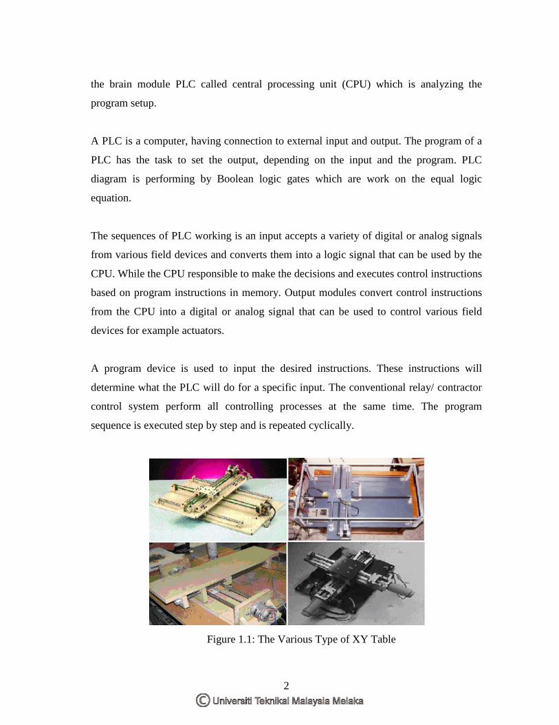
There are various types of XY table being used in machine technology. The apparatus is
applied in positioning element mechanism of lathe, milling and other machine. The most
was applied in control numerical controller (CNC) machining center. The XY table is
use for moves to work of marking, cutting, drilling and others. The named of XY table is
because of the prime activity X and Y axis. Then, there is also Z axis which is for the
vertical axis.
The XY table that used on the project is a just an education training kit and located to
the manufacturing engineering laboratory. There is no any automated controller have
been explore on it. This (manually operate) makes more weakness in controlling
performance of positioning. The suitable controller with familiar and popular in the
productivity industry, PLC is used as a medium improvement the system.
The program being developing to controlling the movement XY table with functioning
the buttoning with consider the bulbs and the safety regulation, then positioning the axis
to the point that make with functioning the magnet to pick and place an object.
PLC offer five medium language but there are only three in Siemens PLC and the
project will done two from it. There are ladder and functional block diagram. The
education training kit of XY table is installing to the program software and connected to
2
the brain module PLC called central processing unit (CPU) which is analyzing the
program setup.
A PLC is a computer, having connection to external input and output. The program of a
PLC has the task to set the output, depending on the input and the program. PLC
diagram is performing by Boolean logic gates which are work on the equal logic
equation.
The sequences of PLC working is an input accepts a variety of digital or analog signals
from various field devices and converts them into a logic signal that can be used by the
CPU. While the CPU responsible to make the decisions and executes control instructions
based on program instructions in memory. Output modules convert control instructions
from the CPU into a digital or analog signal that can be used to control various field
devices for example actuators.
A program device is used to input the desired instructions. These instructions will
determine what the PLC will do for a specific input. The conventional relay/ contractor
control system perform all controlling processes at the same time. The program
sequence is executed step by step and is repeated cyclically.
Figure 1.1: The Various Type of XY Table

3
1.1 Problem Statements
The trend toward automation of production equipment is putting great demands on
people since the early of 1970s. The manufacturers have worked to increase
productivity, capability, reliability, and flexibility by using technologies. In order to
achieve these are making use more and more automation in manufacturing. PLC is one
of the solutions.
The positioning element mechanism numerically controlled XY table using manually is
quietly popularly. Toward the project, although in just an education training kit its will
applies controller system as same as a truly machine. These of developing program
considering to the precaution rule as same in the machine production operation.
1.2 Objectives
By according to the title, the objectives of this project are:
• To recommend new program system to control the positioning axis and
functioning button of XY table.
• To develop new program to control the positioning axis and functioning button
of XY table.
1.3 Scope of Project
The aim of this project is to develop new program that would be control the positioning
of axis. At this stage basic there is important to recognize the hall of thing inside. The

4
scope is consists in three main parts of XY table, PLC and Siemens S7. Below shown
the element scope:
XY Table
• Learn the basic operation.
• Investigate the structure of input and output (switches button and components)
and their address.
PLC and Siemens PLC
• Analyze the features and identify the components on PLC program.
• Investigate and describe the function of each device such as the counter and
relay.
• Study ladder diagram and function block diagram program structure and learn
how to program then minimize the program language to be a simple network
program.
• Investigate the address uses and develop new program regarding to both mode
control.
• Develop the new program which positioning the axis with magnet pick and place
an object to the point making.

5
1.4 Project Planning
Project planning or methodology is the one thing should give consideration to ensure the
project have been done in well condition. There are including the planning on the first
and second stage of project.
Table 1.1: Project Planning for PSM Ι
Table 1.2: Project Planning for PSM ΙΙ