control of secondary units re a4vs axial piston units 92 ...a4vs axial piston units re 92 055/10.97...
TRANSCRIPT

RE 92 055/12.95
1/26
DR DS1n
nsoll
n ist
Control of secondary unitswith
A4VS axial piston units
RE92 055/10.97Replaces: 04.96
Size 40 to 1000 1) Nom. press. 315 bar Max. press. 400 bar
Characteristics:• High response rotary drive
• Reversing open or closed loop operation (four quadrantoperation)
• Power feedback and storage
• Speed, position and torque control with excellent andresponsive control characteristics
• Throttle-free coupling and energy transmission from as manyindependently working motor or generator driven machinesas required, to a common supply line with quasi-constantoperating pressure
• Low losses, especially with partial-load operation
• Compact closed loop electronics (digital or analogue) in Euro-card format
1) Size 1000 on request!
Secondary unit Type A4VSO250DS1 Control and monitoring electronics VT 12000 withfrequency/voltage converter VTS 0102
Functional descriptionSecondary controlled hydrostatic machines connected to apower network with quasi-constant operating pressure meanhigh response, energy saving drives for speed, position andtorque control with power feedback.
No throttling is required for either power take up or feedback, thedisplacement of the machine adjusting itself to the relevantloading. This means that any number of units, operating asmotors or pumps, may be connected in parallel. Four quadrant
operation is even possible in open loop operation, the units usedfor speed and torque reversal being swivelled over the "Zero".This also reverses the direction of flow .
If required an accumulator may be fitted between the primaryand secondary units.
This accumulator is used to cover rapid flow peaks and also tostore energy returned by pump from the secondary unit to thehydraulic circuit, where this energy is not required by any otheractuators. The pre-load pressure and loading condition of theaccumulator, together with the pressure compensated primaryunit and degree of loading on the secondary unit, determine thequasi-constant high pressure in the system.
The specific characteristics of secondary control such as reducingthe amount of equipment required in primary control, combinedwith the possibility of power feedback, the storage of brakingenergy and virtually load-independent speed and positioningaccuracy, open up a wide range of applications.
For further information see "Hydraulic Trainer Vol. 6"(RE 00 293).
Secondary unit
Accumulator
Controlelectronics
Primary unit
Pressurecontroller
Drive Outputnact
ncomm
RE 92 055/10.97

RE 92 055/12.95
2/26
Technical data: Axial piston unit A4VSO (open loop control)
0,5 0,6 0,7 0,8 0,9 1,0
1,5
1,4
1,3
1,2
1,1
1,0
0,9
3,0
2,52,01,81,61,41,21,0
0,8
n o m
ax
n
Inle
t pre
ssur
e p
abs
in b
ar
→
Technical data: Axial piston unit A4VSG (closed loop control)
Determination of inlet pressure pabs at suction port Swith an increase of speed
Note:As the high and low pressure sides do not change, a feedpump may be fitted to port S (see closed loop control).For operating pressure output see closed loop control
Operating pressure inletRecommended boost pressure p
Sp_________________15 bar
Aux. pump inlet pressureSuction pressure pS min (ν = 10 to 300 mm2/s)_________≥ 0,7 bar abs
Operating pressure outletPressure at port A or B
Nominal pressure pN1)___________________________315 bar
Peak pressure pmax
___________________________400 bar
Peak pressure of aux. pump pH max
Boost circuit __________________________30 barPilot circuit, with identical pressure circuit(pressure data to DIN 24 312)
Positioning pressure range
Maximum permissible positioning pressure 1) pmax = 315 bar
Minimum positioning pressure required pmin = operating pressure or 150 bar (see diagram)
Installation position
Optional. The pump housing must be filled on commissioningand remain full during operation.
Case drain pressure
Max. pressure of leakage fluid (housing pressure)
pmax ___________________________________ 4 bar abs.
Note: Shaft seals are of FPM to ISO 1629. All otherseals are Perbunan. The values in the table areguide values and under certain operatingconditions may have to be reduced.
1) from permissible data of servo valve and other system components
10000
4
3
2
1
1000
500,
750
250,
355
125,
180
71 40
2000 3000 4000
Speed n in min -1 →
Definition no max see table on page 3.
250150 315
315
250
200
150
(Size 40 - 125)
(Size 180 - 1000)
max. permissible
Recommended pilot pressurein relation to operating pressure
Operating pressure inletAbsolute pressure at suction port S -generator operation
pabs min
___________________________________ 0,8 bar
pabs max ___________________________________ 30 bar
Spe
ed
→
Cas
e dr
ain
fluid
pre
ssur
e p
abs
in b
ar
→P
ilot p
ress
ure
in b
ar
Operating pressure in bar
Size
Vg
Vg max
Flow →
RE 92 055/12.95
3/26
rechts
links
15°
15°
0°
+ Fax – Fax
Fq
X/2 X/2
X
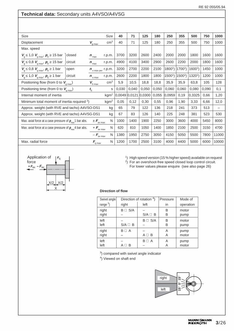
Technical data: Secondary units A4VSO/A4VSG
Size Size 40 71 125 180 250 355 500 750 1000
Displacement Vg max cm3 40 71 125 180 250 355 500 750 1000
Max. speed
Vg ≤ 1,0 V
g max, p
E ≥ 15 bar closed n max
r.p.m. 3700 3200 2600 2400 2000 2000 1800 1600 1600
Vg
≤ 0,8 Vg max
, pE
≥ 15 bar circuit n max
r.p.m. 4900 4100 3400 2900 2600 2200 2000 1800 1600
Vg
≤ 0,8 Vg max
, pE
≥ 1 bar open n o max per
r.p.m. 3200 2700 2200 2100 18001) 17001) 16001) 1450 1000
Vg
≤ 1,0 Vg max
, pE
≥ 1 bar circuit n o max
r.p.m. 2600 2200 1800 1800 15001) 15001) 13201) 1200 1000
Positioning flow (from 0 to Vg max
) VS max
cm3 5,9 10,5 18,8 18,8 35,9 35,9 63,8 105 128
Positioning time (from 0 to Vg max) tS s 0,030 0,040 0,050 0,050 0,060 0,060 0,080 0,090 0,1
Internal moment of inertia kgm2 0,0049 0,0121 0,0300 0,055 0,0959 0,19 0,3325 0,66 1,20
Minimum total moment of inertia required 2) kgm2 0,05 0,12 0,30 0,55 0,96 1,90 3,33 6,66 12,0
Approx. weight (with RVE and tacho) A4VSO-DS1 kg 65 79 122 136 218 241 373 513 –
Approx. weight (with RVE and tacho) A4VSG-DS1 kg 67 83 126 140 225 248 381 523 530
Max. axial force at a case pressure of pmax
1 bar abs. ± Fax max
N 1000 1400 1900 2250 3000 3600 4000 5450 8000
Max. axial force at a case pressure of pmax
4 bar abs. + Fax max
N 620 810 1050 1400 1850 2100 2500 3150 4700
– Fax max N 1380 1950 2750 3050 4150 5050 5500 7800 11000
Max. radial force Fq max N 1200 1700 2500 3100 4000 4400 5000 6000 10000
Application offorce
1) High speed version (15 % higher speed) available on request2) For an overshoot-free speed closed loop control circuit.
For lower values please enquire (see also page 26)
Direction of flow
Swivel angle Direction of rotation 4) Pressure Mode of
range 3) right left in operation
right B ⇒ S/A – B motorright – S/A ⇒ B B pump
left – B ⇒ S/A B motorleft S/A ⇒ B – B pump
right B ⇒ A – A pumpright – A ⇒ B A motor
left – B ⇒ A A pumpleft A ⇒ B – A motor
3) compared with swivel angle indicator4) Viewed on shaft end
left
RE 92 055/05.94
right

RE 92 055/12.95
4/26
FluidMineral oil = no code
Axial piston unitIndustrial swashplate variable unit = A4VSp
N = 350 bar, p
max = 400 bar
Mode of operationSecondary unit for open circuits = O1)Secondary unit for closed circuits = G
Size= Displacement V
g max (cm3) 40 71 125 180 250 355 500 750 1000
Control deviceSpeed control, secondary unit, with built-on servo valve = DS1Speed control, secondary unit, without servo valve = DS1E
SeriesSizes 40, 71 = 1XSizes 125 to 1000 = 2X
Direction of rotationBi-directional = W
SealsPerbunan (shaft sealing ring in FPM) = PFPM seal to ISO 1629 = V
Shaft endParallel with key DIN 6886 = PSplined DIN 5480 = Z
Mounting flange 40 71 125 180 250 355 500 750 1000ISO 4 hole – – – = BISO 8 hole – – – – – – = H
Service line connections A4VSO A4VSGPressure port B SAE at side, 90° offsetSuction port S metric fixing screwsPressure port A SAE at side, same sidePressure port B metric fixing screws
Through drive 40 71 125 180 250 355 500 750 1000without auxiliary pump, without through drive = N00
with through drive to accept an axial piston unitFlange Spigot/shaft to acceptISO 125, 4 hole Splined shaft 32x2x14x9g A4VSO/G 40 = K31ISO 140, 4 hole Splined shaft 40x2x18x9g A4VSO/G 71 – = K33ISO 160, 4 hole Splined shaft 50x2x24x9g A4VSO/G 125 – – = K34ISO 160, 4 hole Splined shaft 50x2x24x9g A4VSO/G 180 – – – = K34ISO 224, 4 hole Splined shaft 60x2x28x9g A4VSO/G 250 – – – – = K35ISO 224, 4 hole Splined shaft 70x3x22x9g A4VSO/G 355 – – – – – = K77ISO 315, 8 hole Splined shaft 80x2x38x9g A4VSO/G 500 – – – – – – = K43ISO 400, 8 hole Splined shaft 90x3x28x9g A4VSO/G 750 – – – – – – – – = K76ISO 250, 8 hole Splined shaft 90x3x28x9g A4VSG 1000 – – – – – – – – = K78With built-on incremental encoder 1000 Imp/U = T03With built-on incremental encoder 2500 Imp/U = T04Increm. encoder with analogue output (standard nmax = 2600 min–1) = T05
Increm. encoder option, through drive fitted with cover = T10
Special tacho mount = T99Euro flange, through drive closed = T00ValveWithout valve block = 0Pilot operated check valve RVE, built-on (with A4VSG 1000 to be ordered separately) = 1
FiltrationWithout filter = NWith built-on filter sandwich plate = Z
= available; = in preparation; – = not available 1) not available for size 1000
Ordering code
A4VS / W –
(Sizes 40 to 1000)
= 13
= 10
–
–
(Sizes 40 to 750)
RE 92 055/05.94

RE 92 055/12.95
5/26
U B MB K2 K3 T R(L)
MA
M1
A
T
P T T1
M2
RKv
T B A P
A
A
Sp
X
SU
E
PStT2 B A
P
U S K1 K2 T R(L)
B1MB
M1
B
B T
XP T
T1M2
PSt PRKv
Sp
T B A P
SU
A
MS
T2 B A
1.1 Hydraulic positioning device (see technical data)
1.2 4 way servo valve (see RE 29 586)
Size Type
40, 71 4WS2EM10-4X/20B2ET315Z8DM125, 180 4WS2EM10-4X/30B2ET315Z8DM250, 355, 500 4WS2EM10-4X/45B2ET315Z8DM750, 1000 4WS2EM10-4X/60B2ET315Z8DM
1.3 Inductive positional transducer IW9-03-DT (see page 24)Alternative: integral piston positional transducer
2 Sandwich plate filter (Ordering code: Z)not required with proportional valve
Size Type
40, 71 DFBH/HC 60Z10D2.0/L24-V-125, 180, 250, 355, 500, 750, 1000 DFBH/HC 110Z10D2.0/L24-V-
3 Incremental encoder GEL 293 (Ordering code: T03 or T04 ) (see page 23)Alternative: AC tacho generator, with or without centrifugal switch
4 Electrically operated check valve RVE (Ordering code: 1) (see page 24)
5 Anti-cavitation valve, to be ordered separately (see page 24)
Associated electronics:
– Control and monitoring device VT 12000(see page 25 and RE 29 775)
– frequency/voltage converter and monitoring electronicsVTS0102(see page 25 and RE 29 761)
– Torque controller card MD1, VTS 0229 (see page 26and RE 29 797)
– Power limiting card LB1 (see page 26 and RE 29 796)
Component parts of a secondary unit
The DS1 speed controller is used to control the swivel angle anddisplacement of a secondary unit at quasi-constant operatingpressure so that the correct torque is made available to maintainthe required speed.In a quasi-constant pressure system the torque is proportionalto the swivel angle or displacement of the axial piston unit. Theswivel angle is fed back by means of an inductive positionaltransducer and the rotational speed by means of a tacho-generator.The unit is supplied complete with a servo valve and flushingplate. Please note the commissioning instructions in RE 07 700and RE 29 586. For less demanding applications the servo valvemay be replaced by a proportional valve.
The control and monitoring electronics VT12000 to RE 29 775and the frequency/voltage converter and monitoring electronicsto RE 29 761 are not included. The system is electronicallyprotected against excessive speeds.
Speed controller DS1
Pilot operated check valve RVE (hydraulic isolator), mounted onthe high pressure port, is returned to the closed position in theevent of an emergency. The secondary unit is then separatedfrom the pressure line to effect braking with power feedback.
In order to prevent cavitation due to the motor running on (orbackwards) during an emergency stop, anti-cavitation valvesmust be used and mounted onto port B1. These valves, checkvalves without spring, must be mounted vertically and are to beordered separately.
1.1 3
1.3
24
5
Closed circuit
Circuit diagram A4VSG
A4VSGXXXDS1/XXW–XXX10T031Z
1.1
1.3
24
3
1.2
Open circuit
Circuit diagram A4VSO
A4VSOXXXDS1/XXW–XXX13T031Z 1.2
Flushing plate
Flushing plate
RE 92 055/04.96

RE 92 055/12.95
6/26
U S K1 K2 T R(L)
B1MB
M1
B
B T
XP T
T1M2
PSt PRKv
Sp
T B A P
SU
A
MS
T2 B A
Ø32 k6
4069,9
SA
E 1
1/2
"
M12
20
1843081,5
21780176
105,5157,515
339,5
399
9010
5856
22
1.5
18
135 91
M10
78
B1
W
M2
227
X
MB
528
T
B
R(L
)
T2
Y
U
144
25
3036
79
22L
R
M10Ø 125 h8
W32
x2x1
4x9g
DIN
548
0
L
R
S
35,7
23,8
49B
18,5
SA
E 3
/4"
50,8
M10
17
48
Sp
RK
v
5
260
10h9
K1
K2
150
7979
150
1585
T1
45°
45°
35
160
M1
Unit dimensions: A4VSO40DS1/1XW–..B13T031Z
Detail Y
Hig
h pr
essu
rese
ries
Detail X
deep
Connections:
B = Pressure port (high pressure series) SAE 3/4"B1 = Additional port M22x1,5S = Suction port (pmax = 30 bar) SAE 1 1/2"K1, K2 = Housing flushing port M22x1,5MB = Test port for operating pressure M14x1,5MS = Pilot oil return M18x1,5M1, M2= Test port for operating pressure 1/4"BSPSp, P = Positioning pressure port M22x1,5PSt = Positioning pressure port 1/2"BSPR(L) = Oil filling/air bleed port M22x1,5T = Oil drain M22x1,5T1 = Leakage/air bleed port 1/4"BSPT2 = Leakage/air bleed port 1/8"BSPU = Flushing port (bearings) M14x1,5RKv = External pilot oil return M22x1,5
Mid
-axi
alpi
ston
uni
t
Pipe threads “BSP” to ISO 228/1
Detail W
Obs
erve
flus
hing
regu
latio
ns to
RE
29
586
Rem
ove
flush
ing
plat
eaf
ter
flush
ing
Nam
epla
te
Flushing plate
Sta
ndar
d pr
essu
rese
ries
dee
p

RE 92 055/12.95
7/26
U B MB K2 K3 T R(L)
MA
M1
A
T
P T T1
M2
RKv
T B A P
A
A
Sp
X
SU
E
PStT2 B A
P
M10
Sp
M1
5 48
260
150
7979
160
45°
45°35
10h9
K 15150
85
205
M2
339,515
105,5157,5
W
MB
B
MA
8T
10 58
22
5290
227
330
561,
5 M10
135Ø32k6
18
78
50,8
20
M10
17 M10
17SA
E 3
/4"
SA
E 3
/4"
B A
823328,828,8
217 22230
U 144
X
T1
R(L
) 25
303622L
R
W32
x2x1
4x9g
DIN
548
079Ø125h8
Unit dimensions: A4VSG40DS1/1XW–..B10T031Z
Connections:
B = Pressure port (high pressure series) SAE 3/4"A = Pressure port (high pressure series) SAE 3/4"K2, K3 = Housing flushing port M22x1,5MA, MB = Test port for operating pressure M14x1,5M1, M2 = Test port for operating pressure 1/4"BSPSp, P = Positioning pressure port M22x1,5PSt = Positioning pressure port 1/2"BSPR(L) = Oil filling/air bleed port M22x1,5T = Oil drain M22x1,5T1 = Leakage/air bleed port 1/4"BSPT2 = Leakage/air bleed port 1/8"BSPU = Flushing port (bearings) M14x1,5RKv = External pilot oil return M22x1,5E = Pilot oil return (feed) M18x1,5
Mid
-axi
al
pist
on u
nit
Detail W
Detail X
Nam
epla
te
deep
deep
Hig
h pr
essu
rese
ries
Hig
h pr
essu
rese
ries
Pipe threads “BSP” to ISO 228/1
Obs
erve
flus
hing
regu
latio
ns to
RE
29
586
Rem
ove
flush
ing
plat
e af
ter
flush
ing
Flushing plate
RE 92 055/12.95
8/26
U S K1 K2 T R(L)
B1MB
M1
B
B T
XP T
T1M2
PSt PRKv
Sp
T B A P
SU
A
MS
T2 B A
Ø40 k6
5077,8
SA
E 2
"
M12
20
214,53495
21292,5176
115,5167,515
349,5
427
101
107068
28
1.5
18
152 106
M12
B1
W
M2
254
MS
X
MB
618
T
B
R(L
)
T2
Y
U
166
27
2745
92
28L
R
M12Ø 140 h8
W40
x2x1
8x9g
DIN
548
0
L
R
S
42,9
27,8
52B
25S
AE
1"
57,2
M12
17
48
Sp
RK
v
296
12h9
K1
K2
170
9393
170
1597
T1
45°
45°
43
180
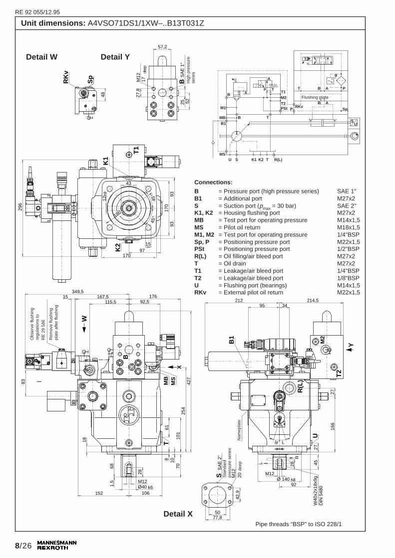
83Unit dimensions: A4VSO71DS1/1XW–..B13T031Z
Detail W Detail Y
deep
Hig
h pr
essu
rese
ries
Connections:
B = Pressure port (high pressure series) SAE 1"B1 = Additional port M27x2S = Suction port (pmax = 30 bar) SAE 2"K1, K2 = Housing flushing port M27x2MB = Test port for operating pressure M14x1,5MS = Pilot oil return M18x1,5M1, M2 = Test port for operating pressure 1/4"BSPSp, P = Positioning pressure port M22x1,5PSt = Positioning pressure port 1/2"BSPR(L) = Oil filling/air bleed port M27x2T = Oil drain M27x2T1 = Leakage/air bleed port 1/4"BSPT2 = Leakage/air bleed port 1/8"BSPU = Flushing port (bearings) M14x1,5RKv = External pilot oil return M22x1,5
Nam
epla
te
Detail X
–
Pipe threads “BSP” to ISO 228/1
Obs
erve
flus
hing
regu
latio
ns to
RE
29
586
Rem
ove
flush
ing
plat
e af
ter
flush
ing
Sta
ndar
dpr
essu
re s
erie
s
deep
Flushing plate
RE 92 055/12.95
9/26
M12
Sp
48
296
170
9393
180
45°
45°43
K
15170
97
210,5
M1
349,515
115,5167,5
WM
B
B AM
A8
T10
70
28
6110
1
258,
5
681,
5 M12
152Ø40k6
18
83
57,2
25
M12
17SA
E 1
"
B A
37,527,8
212 23234
U
166
X
T1
R(L
)
27
2745L
R
W40
x2x1
8x9g
DIN
548
092Ø140h8
12h9
89,527,8
57,2
M12
17 SA
E 1
"
28
106
RK
v
358
U B MB K2 K3 T R(L)
MA
M1
A
T
P T T1
M2
RKv
T B A P
A
A
Sp
X
SU
E
PStT2 B A
P
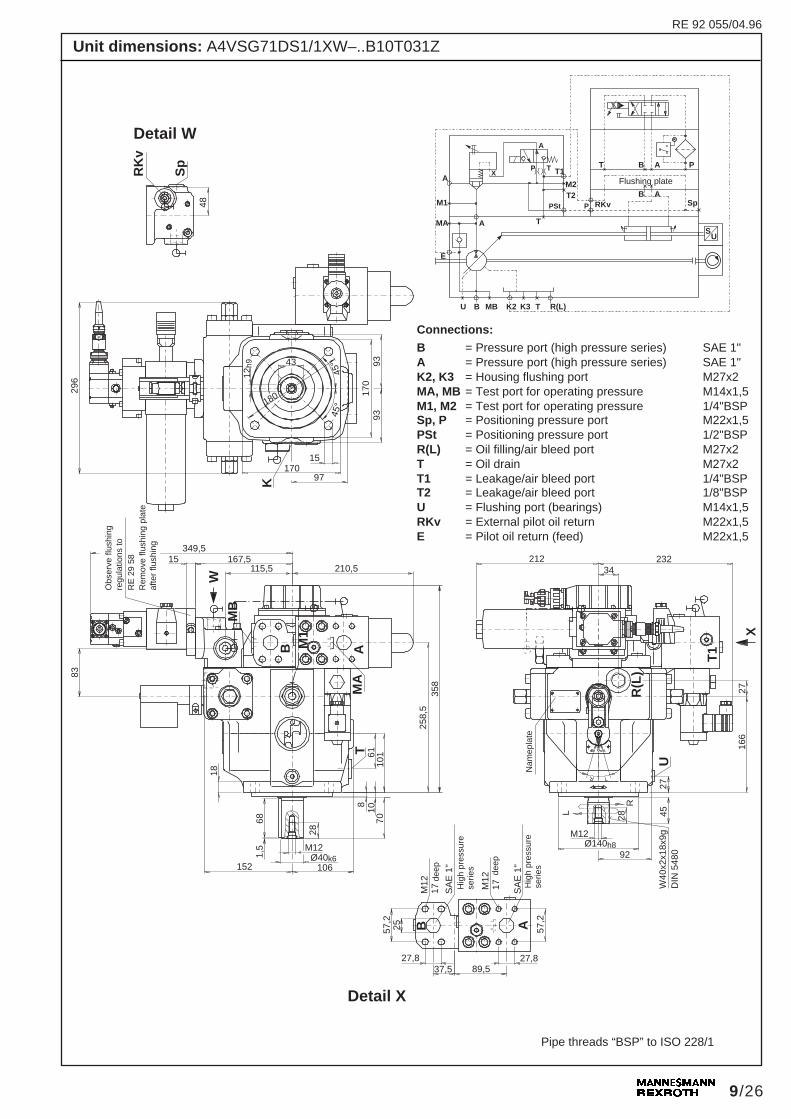
Unit dimensions: A4VSG71DS1/1XW–..B10T031Z
Detail W
Connections:
B = Pressure port (high pressure series) SAE 1"A = Pressure port (high pressure series) SAE 1"K2, K3 = Housing flushing port M27x2MA, MB = Test port for operating pressure M14x1,5M1, M2 = Test port for operating pressure 1/4"BSPSp, P = Positioning pressure port M22x1,5PSt = Positioning pressure port 1/2"BSPR(L) = Oil filling/air bleed port M27x2T = Oil drain M27x2T1 = Leakage/air bleed port 1/4"BSPT2 = Leakage/air bleed port 1/8"BSPU = Flushing port (bearings) M14x1,5RKv = External pilot oil return M22x1,5E = Pilot oil return (feed) M22x1,5
Detail X
Hig
h pr
essu
rese
ries de
ep
Hig
h pr
essu
rese
ries
Nam
epla
te
Pipe threads “BSP” to ISO 228/1
Flushing plate
Obs
erve
flus
hing
regu
latio
ns to
RE
29
58R
emov
e flu
shin
g pl
ate
afte
r flu
shin
g
deep
RE 92 055/04.96

RE 92 055/12.95
10/26
U S K1 K2 T R(L)
B1MB
M1
B
B T
XP T
T1M2
PSt P RKv Sp
T B A P
SU
A
MS2
T2 B A
MS
Ø50 k6
6388,9
SA
E 2
1/2
"
M12
17
232,536114,5
112,5188,5
14419615
378
515
125
108280
36
1.5
22
185,5 120,5
M16
B1
W
M2
310
MS
X
M1,
MB
708
T
B
R(L
)
T2
Y
U
203
30
3354
112
36L
R
M16Ø 160 h8
W50
x2x2
4x9g
DIN
548
0
L
R
S
50,8
31,8
63B
30S
AE
1 1
/4"
66,7
M14
19
48
Sp
RK
v
272
14h9
K1
K2
200
111,
5
200
20114,5
T1
45°
45°
53,5
200
111,
5
177
95
Unit dimensions: A4VSO125DS1/2XW–..B13T031Z
Detail X
Nam
epla
te
Detail W
Detail Y
deep
Hig
h pr
essu
rese
ries
Connections:
B = Pressure port (high pressure series) SAE 1 1/4"B1 = Additional port M33x2S = Suction port (pmax = 30 bar) SAE 2 1/2"K1, K2 = Housing flushing port M33x2MB = Test port for operating pressure M14x1,5MS = Test port for suction pressure M14x1,5MS2 = Pilot oil return 1/2"BSPM1, M2 = Test port for operating pressure 1/4"BSPSp, P = Positioning pressure port M22x1,5PSt = Positioning pressure port 1/2"BSPR(L) = Oil filling/air bleed port M33x2T = Oil drain M33x2T1 = Leakage/air bleed port 1/4"BSPT2 = Leakage/air bleed port 1/4"BSPU = Flushing port (bearings) M14x1,5RKv = External pilot oil return M22x1,5
Pipe threads “BSP” to ISO 228/1
Obs
erve
flus
hing
regu
latio
ns to
RE
29
586
Rem
ove
flush
ing
plat
eaf
ter
flush
ing
Sta
ndar
dpr
essu
rese
ries
Flushing plate
deep
RE 92 055/10.97

RE 92 055/12.95
11/26
U B MB K2 K3 T R(L)
MA
M1
A
T
P T T1
M2
RKv
T B A P
A
A
Sp
X
SU
E
PStT2 B A
P
M16
Sp
48
354
200
200
45°
45°
53,5
K 20
200
246,5
37815
144196
W
B A
8 1082
36
70
125
315
801,
5 M16
185,5Ø50k6
22
66,7
32
M14
19
B
A
31,8
272 25036
U
203
XT1
R(L
)
30
54L
R
W50
x2x2
4x9g
DIN
548
0112Ø160h8
14h9
104,541,5
SA
E 1
1/4
"
36
120,5
M2
M1
RK
v
111,
511
1,5
114,5136
31,8
SA
E 1
1/4
"
M14
19
33
MA
MB
T
414
95
Unit dimensions: A4VSG125DS1/2XW–..B10T031Z
Nam
epla
te
Detail X
Detail W
Connections:
B = Pressure port (high pressure series) SAE 1 1/4"A = Pressure port (high pressure series) SAE 1 1/4"K2, K3 = Housing flushing port M33x2MA, MB = Test port for operating pressure M14x1,5M1, M2 = Test port for operating pressure 1/4"BSPSp, P = Positioning pressure port M22x1,5PSt = Positioning pressure port 1/2"BSPR(L) = Oil filling/air bleed port M33x2T = Oil drain M33x2T1 = Leakage/air bleed port 1/4"BSPT2 = Leakage/air bleed port 1/4"BSPU = Flushing port (bearings) M14x1,5RKv = External pilot oil return M22x1,5E = Pilot oil return (feed) M22x1,5
Hig
h pr
essu
rese
ries
Hig
h pr
essu
rese
ries
Pipe threads “BSP” to ISO 228/1
Obs
erve
flush
ing
regu
latio
nsto
RE
29
586
Rem
ove
flush
ing
plat
e af
ter
flush
ing
deep
deep
Flushing plate
RE 92 055/04.96
RE 92 055/12.95
12/26
U S K1 K2 T R(L)
B1MB
M1
B
B T
XP T
T1M2
PSt P RKv Sp
T B A P
SU
A
MS2
T2 B A
MS
Ø50 k6
75106,4
SA
E 3
"
M16
24
24036122
116188,5
14419615
378
523
125
108280
36
1.5
22
185,5 120,5
M16
B1
W
M2
318
MS
X
M1,
MB
708
T
B
R(L
)
T2
Y
U
203
30
3354
112
36L
R
M16Ø 160 h8
W50
x2x2
4x9g
DIN
548
0
L
R
S
61,9
31,8
63B
30S
AE
1 1
/4"
66,7
M14
19
48
Sp
RK
v
272
9535
4
14h9
K1
K2
200
111,
5
200
20114,5
T1
45°
45°
53,5
200
111,
5
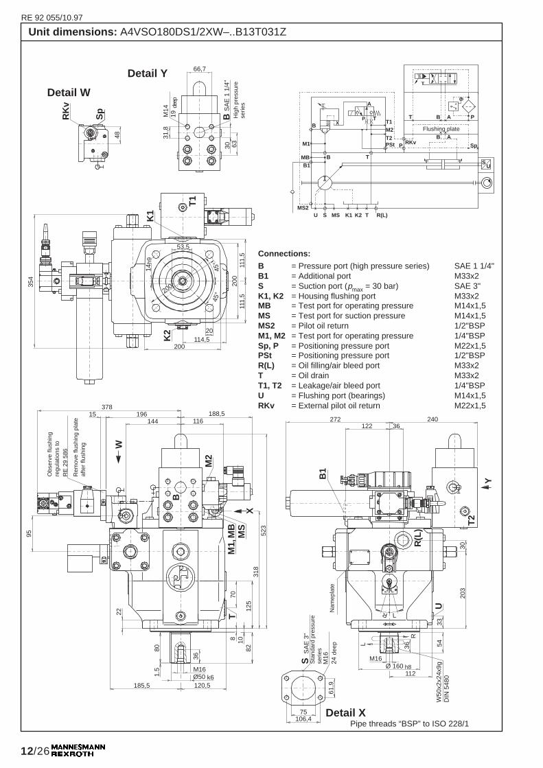
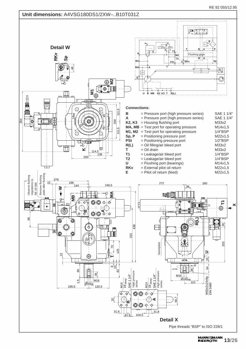
Unit dimensions: A4VSO180DS1/2XW–..B13T031Z
Connections:
B = Pressure port (high pressure series) SAE 1 1/4"B1 = Additional port M33x2S = Suction port (pmax = 30 bar) SAE 3"K1, K2 = Housing flushing port M33x2MB = Test port for operating pressure M14x1,5MS = Test port for suction pressure M14x1,5MS2 = Pilot oil return 1/2"BSPM1, M2 = Test port for operating pressure 1/4"BSPSp, P = Positioning pressure port M22x1,5PSt = Positioning pressure port 1/2"BSPR(L) = Oil filling/air bleed port M33x2T = Oil drain M33x2T1, T2 = Leakage/air bleed port 1/4"BSPU = Flushing port (bearings) M14x1,5RKv = External pilot oil return M22x1,5
Detail X
Nam
epla
te
deep
Hig
h pr
essu
rese
ries
Detail W
Detail Y
Pipe threads “BSP” to ISO 228/1
Flushing plate
Obs
erve
flus
hing
regu
latio
ns to
RE
29
586
Rem
ove
flush
ing
plat
eaf
ter
flush
ing
Sta
ndar
dpr
essu
rese
ries
deep
RE 92 055/10.97
RE 92 055/12.95
13/26
U B MB K2 K3 T R(L)
MA
M1
A
T
P T T1
M2
RKv
T B A P
A
A
Sp
X
SU
E
PStT2 B A
P
M16
Sp
48
354
200
200
45°
45°
53,5
K 20
200
246,5
37815
144196
W
B A
8 1082
36
70
125
315
801,
5 M16
185,5Ø50k6
22
66,7
32
M14
19
B
A
31,8
272 26036
U
203
XT1
R(L
)
30
54L
R
W50
x2x2
4x9g
DIN
548
0112Ø160h8
14h9
104,541,5
SA
E 1
1/4
"
36
120,5
M2
M1
RK
v
111,
511
1,5
114,5136
31,8
SA
E 1
1/4
"
M14
19
33
MA
MB
T
438
95
Unit dimensions: A4VSG180DS1/2XW–..B10T031Z
Nam
epla
teH
igh
pres
sure
serie
s
Hig
h pr
essu
rese
ries
Detail W
Connections:
B = Pressure port (high pressure series) SAE 1 1/4"A = Pressure port (high pressure series) SAE 1 1/4"K2, K3 = Housing flushing port M33x2MA, MB = Test port for operating pressure M14x1,5M1, M2 = Test port for operating pressure 1/4"BSPSp, P = Positioning pressure port M22x1,5PSt = Positioning pressure port 1/2"BSPR(L) = Oil filling/air bleed port M33x2T = Oil drain M33x2T1 = Leakage/air bleed port 1/4"BSPT2 = Leakage/air bleed port 1/4"BSPU = Flushing port (bearings) M14x1,5RKv = External pilot oil return M22x1,5E = Pilot oil return (feed) M22x1,5
Detail XPipe threads “BSP” to ISO 228/1
Obs
erve
flus
hing
regu
latio
ns to
RE
29
586
Rem
ove
flush
ing
plat
e af
ter
flush
ing
deep
deep
Flushing plate
RE 92 055/12.95
14/26
U S K1 K2 T R(L)
B1MB
M1
B
B T
XP T
T1M2
PSt P RKv Sp
T B A P
SU
A
MS2
T2 B A
MS
40615 224 144
188,5
W
M2
68
MS
M1,
MB
X
380
830
90
100
3
42
M20
233 151Ø60m6
B
T15
010
105
SS
AE
3"
M16
2461
,9
75106,4
585
B1
272146
Y
T2
27440
R(L
)
U
M20
42
L
R
7044
248
144Ø224h8
W60
x2x2
8x9g
DIN
548
0
40
48
Sp
RK
v
79,4
M16
2336
,5
6840
BS
AE
1 1
/2"
K1
T1
64
K2
424
265
143,
514
3,5
24265
144,5
280
18h9 45
°45
°
112
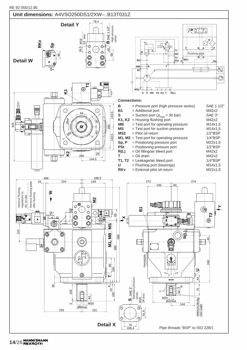
Unit dimensions: A4VSO250DS1/2XW–..B13T031Z
Connections:
B = Pressure port (high pressure series) SAE 1 1/2"B1 = Additional port M42x2S = Suction port (pmax = 30 bar) SAE 3"K1, K2 = Housing flushing port M42x2MB = Test port for operating pressure M14x1,5MS = Test port for suction pressure M14x1,5MS2 = Pilot oil return 1/2"BSPM1, M2 = Test port for operating pressure 1/4"BSPSp, P = Positioning pressure port M22x1,5PSt = Positioning pressure port 1/2"BSPR(L) = Oil filling/air bleed port M42x2T = Oil drain M42x2T1, T2 = Leakage/air bleed port 1/4"BSPU = Flushing port (bearings) M14x1,5RKv = External pilot oil return M22x1,5
Detail W
Detail Y
Nam
epla
te
deep
Hig
h pr
essu
rese
ries
Pipe threads “BSP” to ISO 228/1
Obs
erve
flus
hing
regu
latio
ns to
RE
29
586
Rem
ove
flush
ing
plat
eaf
ter
flush
ing
Sta
ndar
d pr
essu
rese
ries
deep
Flushing plate
Detail X

RE 92 055/12.95
15/26
M20
Sp
48
424
265
45°
45°
64
K
24
265
255,5406
15 224
W
B A8
1010
5
42
9015
0
386
100
3 M20
233Ø60m6
30
79,4
38
M16
21
272 29040
248
X
T1
R(L
)
40
70L
R
144Ø224h8
18h9
50,5
SA
E 1
1/2
"
42
151
M2
M1
RK
v
143,
514
3,5
144,5
36,5
SA
E 1
1/2
"
M16
21
44
MA
MB
T
497,
5
280
AB79,4
36,5118,5
W60
x2x2
8x9g
DIN
548
0T
2
238
U
112
U B MB K2 K3 T R(L)
MA
M1
A
T
P T T1
M2
RKv
T B A P
A
A
Sp
X
SU
E
PStT2 B A
P
Unit dimensions: A4VSG250DS1/2XW–..B10T031Z
Detail X
Detail W
Nam
epla
te
Hig
h pr
essu
rese
ries
Connections:
B = Pressure port (high pressure series) SAE 1 1/2"A = Pressure port (high pressure series) SAE 1 1/2"K2, K3 = Housing flushing port M42x2MA, MB = Test port for operating pressure M14x1,5M1, M2 = Test port for operating pressure 1/4"BSPSp, P = Positioning pressure port M22x1,5PSt = Positioning pressure port 1/2"BSPR(L) = Oil filling/air bleed port M42x2T = Oil drain M42x2T1 = Leakage/air bleed port 1/4"BSPT2 = Leakage/air bleed port 1/4"BSPU = Flushing port (bearings) M14x1,5RKv = External pilot oil return M22x1,5E = Pilot oil return (feed) M22x1,5
Pipe threads “BSP” to ISO 228/1
Flushing plate
Hig
h pr
essu
rese
ries
Obs
erve
flus
hing
regu
latio
ns to
RE
29
586
Rem
ove
flush
ing
plat
e af
ter
flush
ing
deep
deep

RE 92 055/12.95
16/26
U S K1 K2 T R(L)
B1MB
M1
B
B T
XP T
T1M2
PSt P RKv Sp
T B A P
SU
A
MS2
T2 B A
MS
40615 224 144
188,5
W
M2
68
MS
M1,
MB
X
393
830
90
100
4,5
42
M20
233 151Ø70m6
B
T15
010
105
598
B1
272150
Y
T2
27840
R(L
)
U
M20
42
L
R
8244
248
144Ø224h8
W70
x3x2
2x9g
DIN
548
0
40
48
Sp
RK
v79,4
M16
2336
,5
6840
BS
AE
1 1
/2"
K1
T1
64
K2
424
265
143,
514
3,5
24265
144,5
280
18h9 45
°45
°53
SS
AE
4"
M16
2461
,9
75106,4
112
Unit dimensions: A4VSO355DS1/2XW–..B13T031Z
Detail W
Hig
h pr
essu
rese
ries
deep
Detail Y
Connections:
B = Pressure port (high pressure series) SAE 1 1/2"B1 = Additional port M42x2S = Suction port (pmax = 30 bar) SAE 4"K1, K2 = Housing flushing port M42x2MB = Test port for operating pressure M14x1,5MS = Test port for suction pressure M14x1,5MS2 = Pilot oil return 1/2"BSPM1, M2 = Test port for operating pressure 1/4"BSPSp, P = Positioning pressure port M22x1,5PSt = Positioning pressure port 1/2"BSPR(L) = Oil filling/air bleed port M42x2T = Oil drain M42x2T1, T2 = Leakage/air bleed port 1/4"BSPU = Flushing port (bearings) M18x1,5RKv = External pilot oil return M22x1,5
Pipe threads “BSP” to ISO 228/1
Nam
epla
te
Obs
erve
flus
hing
regu
latio
ns to
RE
29
586
Rem
ove
flush
ing
plat
eaf
ter
flush
ing
Sta
ndar
d pr
essu
rese
ries
deep
Flushing plate
RE 92 055/04.96
Detail X

RE 92 055/12.95
17/26
M20
Sp
48
484 26
5
45°
45°
74,5
K
24
265
255,5406
224
W
B A8
1010
5
42
9015
0
393
100
4,5 M20
233Ø70m6
30
79,4
38
M16
21
272 31040
248
X
T1
R(L
)
40
13L
R
144Ø224h8
20h9
50,5
SA
E 1
1/2
" 42
151
M2
M1
RK
v
143,
514
3,5
144,5
36,5
SA
E 1
1/2
"
M16
21
44
MA
MB
T
527
280
AB79,4
118,5
W70
x3x2
2x9g
DIN
548
0T
2U
15
53
36,5
53
82
112
Unit dimensions: A4VSG355DS1/2XW–..B10T031Z
Detail W
deep
deep
Hig
h pr
essu
rese
ries
Hig
h pr
essu
rese
ries
Detail X
Connections:B = Pressure port (high pressure series) SAE 1 1/2"A = Pressure port (high pressure series) SAE 1 1/2"K2, K3 = Housing flushing port M42x2MA, MB = Test port for operating pressure M14x1,5M1, M2 = Test port for operating pressure 1/4"BSPSp, P = Positioning pressure port M22x1,5PSt = Positioning pressure port 1/2"BSPR(L) = Oil filling/air bleed port M42x2T = Oil drain M42x2T1 = Leakage/air bleed port 1/4"BSPT2 = Leakage/air bleed port 1/4"BSPU = Flushing port (bearings) M18x1,5RKv = External pilot oil return M22x1,5E = Pilot oil return (feed) M22x1,5
Pipe threads “BSP” to ISO 228/1
Nam
epla
te
Obs
erve
flus
hing
regu
latio
ns to
RE
29
586
Rem
ove
flush
ing
plat
eaf
ter
flush
ing
Flushing plate
U B MB K2 K3 T R(L)
MA
M1
A
T
P T T1
M2
RKv
T B A P
A
A
Sp
X
SU
E
PStT2 B A
P
RE 92 055/04.96

RE 92 055/12.95
18/26
PRKv
MA2
T AB P
SU
S K1 K2 T R(L)
B1
MB
M1
B
BT
PSt
M2
T1
A
P TX
MP
U MS R4 R2R3 R5 R7R6
MB2AB
T2
MS2
B 945044
,4
96,8
M20
23 SA
E 2
"
92,1
125152,4
SM16
23
SA
E 5
"
510
159
190
Ø 360
Ø 405
22h9
R5
R6
R7
R2
R3
R4
22°3
0'
45°
K2
85
8 x 45 °
(= 360
°)
180
155
80M
B1
16+
5
180
130
47
45°
Ø 80m6
42
125
3 M20
280392
MP
104
122,
5
M2
T
B
Ø 230+5
Ø 315h8
303
50
B1
14
U13
30°
10°
42R
M20
90
R10
Ø 225
189
W80
x3x2
5x9g
DIN
548
030
279
50
139,
5
48
MA
R (
L)
441
736 T
2
L
K1
281
110
110
T1
159
190
24 161190190
M1
X
MB
2
Y
161
MS
Unit dimensions: A4VSO500DS1/2XW–..H13T031Z
Connections:B = Pressure port (high press. series) SAE 2"B1 = Additional port M48x2S = Suction port (pmax = 30 bar) SAE 5"K1, K2 = Housing flushing port M48x2MB = Test port for operating pressure M18x1,5MS = Test port for suction pressure M18x1,5MS2 = Pilot oil return M27x2M1, M2 = Test port for operating pressure 1/4"BSPP = Positioning pressure port M27x2PSt = Positioning pressure port 3/4"BSPR(L) = Oil filling/air bleed port M48x2T = Oil drain M48x2T1, T2 = Leakage/air bleed port 1/4"BSPU = Flushing port (bearings) M18x1,5RKv = External pilot oil return M27x2MA2, MB2, MP = Test port for positioning press. M14x1,5R2 to R7 = Air bleed adjustment M14x1,5
Detail Y Detail Xde
ep deep
Hig
h pr
essu
re s
erie
s
Nam
epla
te
for
liftin
g ey
e M
16-D
IN58
0
Sta
ndar
d pr
essu
rese
ries
Flushing plate
Obs
erve
flus
hing
reg
ulat
ions
to R
E 2
9 58
6
Rem
ove
flush
ing
plat
eaf
ter
flush
ing
Pipe threads “BSP” to ISO 228/1
RE 92 055/04.96

RE 92 055/12.95
19/26
RKvMP
T B A P
SU
B K2 T R(L)
MA1
M1
A
T
M2
T1
A
P TX
MA2
U MB1 R4 R2R3 R5 R7R6K3
A
E
T2MB2B A
PPSt
Unit dimensions: A4VSG500DS1/2XW–..H10T031Z
Detail X
Connections:B = Pressure port (high pressure series) SAE 2"A = Pressure port (high pressure series) SAE 2"K2, K3 = Housing flushing port M48x2MA1, MB1 = Test port for operating pressure M18x1,5M1, M2 = Test port for operating pressure 1/4"BSPP = Positioning pressure port M27x2PSt = Positioning pressure port 3/4"BSPR(L) = Oil filling/air bleed port M48x2T = Oil drain M48x2T1, T2 = Leakage/air bleed port 1/4"BSPU = Flushing port (bearings) M18x1,5RKv = External pilot oil return M27x2E = Pilot oil return (feed) M27x2MA2, MB2, MP = Test port for positioning press. M14x1,5R2 to R7 = Air bleed adjustment M14x1,5
for
liftin
g ey
e M
16-D
IN58
0
Nam
epla
t
deep
deep
Hig
h pr
essu
rese
ries
Hig
h pr
essu
rese
ries
SA
E 2
"
Pipe threads “BSP” to ISO 228/1
Obs
erve
flus
hing
regu
latio
ns to
RE
29
586
Rem
ove
flush
ing
plat
eaf
ter
flush
ing
Flushing plate
RE 92 055/04.96
10°
M20
22°3
0´
85
K 161
281
355
MP
B A
45°
16+
5
8013
0
435
125
M20
392
Ø80m6
96,8
50
31550
279
X
T1
50
R10
189Ø315h8
22h9
60
M2M
1
R5
159
190
44,5
SA
E 2
"
M20
24
90
MA
1
MB
1
Ø360
AB97
154
W80
x3x2
5x9g
DIN
548
0
42
R6
R7
24
159
190
190
Ø405
110
110
510
48
190
R4
R3
R2
45°
8x45° (=
360°
)
R(L
)
T
3
4718
015
5
42
280
M20
24
MB
2
3014
0
R
R
Ø225Ø230+5
U
4814
6
1413
30°
MA
2
L
571,
5
597
104
122,
5
RE 92 055/12.95
20/26
PRKv
MA2
T AB P
SU
S K1 K2 T R(L)
B1
MB
M1
B
BT
PSt
M2
T1
A
P TX
MP
U MS R4 R2R3 R5 R7R6
MB2AB
T2
MS2
125152,4
92,1
SS
AE
5"
M16
;
44,4
M20
; 96,8 SA
E 2
"
9450
B
25h9
K1 203,5
T1
R7
R6
R5
K2
R4
R3
R2
582
110
110
95 Ø 450
Ø 490
182
232
182 23
2
8 x 45° (= 36
0°)
22°3
0'
45°17822
232232
200
M2
MS
768
X47
316
189T
M1
MB
116
+5
180
130
47
45°
Ø 90m6
50
125
4,5 M24
317427
MP
R (
L)
114
132,
5
Ø 263+5
Ø 400h8
185 32750
MB
2
MA
B1
1514
658
14
Y
T2
U13 30°
10°
50
L
R
M24
105
R10
Ø 225
234
W90
x3x2
8x9g
DIN
548
0
155
32
301
50
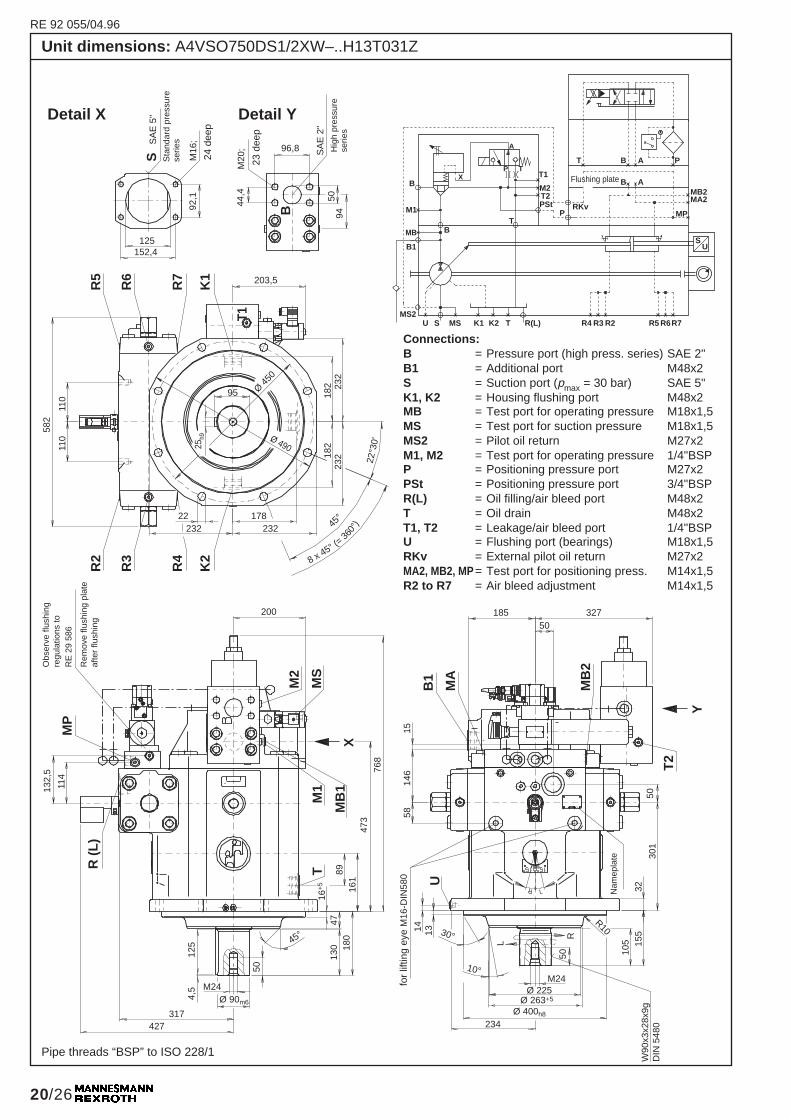
Unit dimensions: A4VSO750DS1/2XW–..H13T031Z
Connections:B = Pressure port (high press. series) SAE 2"B1 = Additional port M48x2S = Suction port (pmax = 30 bar) SAE 5"K1, K2 = Housing flushing port M48x2MB = Test port for operating pressure M18x1,5MS = Test port for suction pressure M18x1,5MS2 = Pilot oil return M27x2M1, M2 = Test port for operating pressure 1/4"BSPP = Positioning pressure port M27x2PSt = Positioning pressure port 3/4"BSPR(L) = Oil filling/air bleed port M48x2T = Oil drain M48x2T1, T2 = Leakage/air bleed port 1/4"BSPU = Flushing port (bearings) M18x1,5RKv = External pilot oil return M27x2MA2, MB2, MP = Test port for positioning press. M14x1,5R2 to R7 = Air bleed adjustment M14x1,5
Sta
ndar
d pr
essu
rese
ries
24 d
eep
23 d
eep
for
liftin
g ey
e M
16-D
IN58
0
Nam
epla
te
Detail X Detail Y
Hig
h pr
essu
rese
ries
Pipe threads “BSP” to ISO 228/1
Obs
erve
flus
hing
regu
latio
ns to
RE
29
586
Rem
ove
flush
ing
plat
eaf
ter
flush
ing
Flushing plate
RE 92 055/04.96

RE 92 055/12.95
21/26
RKvMP
T B A P
SU
B K2 T R(L)
MA1
M1
A
T
M2
T1
A
P TX
MA2
U MB1 R4 R2R3 R5 R7R6K3
A
T2MB2B A
PPSt
304
16189
MA
116
+5
180
130
47
45°
Ø 90m6
50
125
4,5 M24
317427
MP
R (
L)
114
132,
5
MB
2
MB
1
A
355180
T
B
25h9
M1
319
R7
R6
R5
K
R4
R3
R2
582
110
110
95Ø 45
0
Ø 490 182
232
182 23
2
8 x 45° (=36
0°)
22°3
0'
45°17822
232232
M2
96,8
50 96,8
44,515460
44,5
M20
SA
E 2
"
SA
E 2
"
Ø 263+5
Ø 400h8
37550
RK
v
1514
658
14
X
T1
U13 30°
10°
50
L
R
M24
105
R10
Ø 225
234
W90
x3x2
8x9g
DIN
548
0
32
301
50
467
50
155
119
MA
2
629
622
Unit dimensions: A4VSG750DS1/2XW–..H10T031Z
24 d
eep
Detail X
Hig
h pr
essu
rese
ries
for
liftin
g ey
e M
16-D
IN58
0
Connections:B = Pressure port (high press. series) SAE 2"A = Pressure port (high press. series) SAE 2"K2, K3 = Housing flushing port M48x2MA1, MB1 = Test port for operating pressure M18x1,5M1, M2 = Test port for operating pressure 1/4"BSPP = Positioning pressure port M27x2PSt = Positioning pressure port 3/4"BSPR(L) = Oil filling/air bleed port M48x2T = Oil drain M48x2T1, T2 = Leakage/air bleed port 1/4"BSPU = Flushing port (bearings) M18x1,5RKv = External pilot oil return M27x2MA2, MB2, MP = Test port for positioning press. M14x1,5R2 to R7 = Air bleed adjustment M14x1,5
Flushing plate
Obs
erve
flus
hing
regu
latio
ns to
RE
29
586
Rem
ove
flush
ing
plat
e af
ter
flush
ing
Nam
epla
te
Pipe threads “BSP” to ISO 228/1
RE 92 055/04.96
Hig
h pr
essu
rese
ries
RE 92 055/12.95
22/26
Unit dimensions: A4VSG1000... on request!
RE 92 055/04.96RE 92 055/10.97
RE 92 055/12.95
23/26
1st track
1st track
2nd track
2nd track
G
FE D
J
I
C
BAH
T
US = 5 V ± 5 %T
track 2
track 2
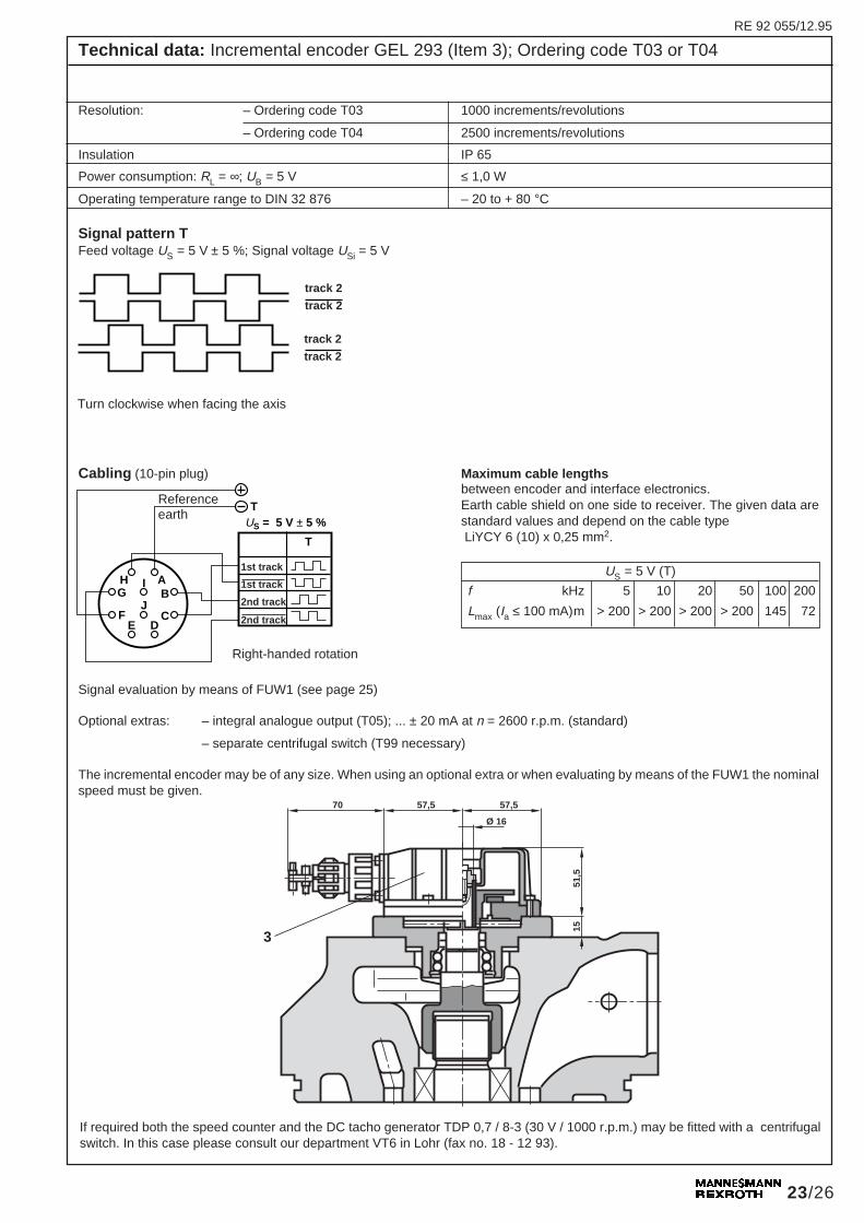
Technical data: Incremental encoder GEL 293 (Item 3); Ordering code T03 or T04
Resolution: – Ordering code T03 1000 increments/revolutions
– Ordering code T04 2500 increments/revolutions
Insulation IP 65
Power consumption: RL = ∞; UB = 5 V ≤ 1,0 W
Operating temperature range to DIN 32 876 – 20 to + 80 °C
Signal evaluation by means of FUW1 (see page 25)
Optional extras: – integral analogue output (T05); ... ± 20 mA at n = 2600 r.p.m. (standard)
– separate centrifugal switch (T99 necessary)
The incremental encoder may be of any size. When using an optional extra or when evaluating by means of the FUW1 the nominalspeed must be given.
Signal pattern TFeed voltage US = 5 V ± 5 %; Signal voltage USi = 5 V
Cabling (10-pin plug) Maximum cable lengthsbetween encoder and interface electronics.Earth cable shield on one side to receiver. The given data arestandard values and depend on the cable type LiYCY 6 (10) x 0,25 mm2.
US = 5 V (T)
f kHz 5 10 20 50 100 200
Lmax (Ia ≤ 100 mA)m > 200 > 200 > 200 > 200 145 72
Turn clockwise when facing the axis
Right-handed rotation
Referenceearth
3
70 57,5 57,5
51,5
15
Ø 16
If required both the speed counter and the DC tacho generator TDP 0,7 / 8-3 (30 V / 1000 r.p.m.) may be fitted with a centrifugalswitch. In this case please consult our department VT6 in Lohr (fax no. 18 - 12 93).
track 2
track 2

RE 92 055/12.95
24/26
Technical data: Inductive positional transducer IW9-03-DT (Item 1.3)
Anti-cavitation valve (RE 20 375)
Size Type
40 S 10 A 0.0
71 S 15 A 0.0
125 S 20 A 0.0
180 S 20 A 0.0
250 S 25 A 0.0
355 S 25 A 0.0
500 S 30 A 0.0
750 S 30 A 0.0
Note: For A4VSO units these anti-cavitation valves are piped to port B. This is not necessary with the A4VSG for which integralanti-cavitation valves are available.
Data – Swivel angle transducer
Electrical measuring system half bridge differential
Control stroke ± 4 mm
Tolerance on linearity ≤ 1,5 %
Frequency f 5 kHz
Coil resistance – between ports 1 and 2 32 Ω
(at 20 °C) – between port 2 and 46 Ω
– between port 1 and 32 Ω
Electrical connections Plug connections to DIN 43 650 - BFZ-Pg9
Insulation of plug connections to DIN 40 050 IP 65
Technical data: Anti-cavitation valve (Item 5), to be ordered separately
Technical data: Electrically operated check valve RVE A4VS (Item 4); Ordering code 1
Electrical data (see directional poppet valve M–3SEW6, RE 22 057)
DC voltage V 24
Power required W 27
Duty cycle continuous
Insulation to DIN 40 050 IP 65
Hydraulic data (see logic elements Type LC.., RE 81 010)
Size Logic element (integral) in housing max. flow m Qmax
in L/min at pressure drop of 5 bar
40 LC25B40E-6X/ AG 55 27 400
71 LC25B40E-6X/ AG 55 26 400
125 LC32B40E-6X/ AG 55 24 600
180 LC32B40E-6X/ AG 55 24 600
250 LC32B40E-6X/ AG 55 25 600
355 LC32B40E-6X/ AG 55 25 600
500 LC40B40E-6X/ AG 55 29 1000
750 LC50B40E-6X/ AG 55 79 1600
1000 LC50B40E-6X/ AG 55 79 1600
RE 92 055/05.94

RE 92 055/12.95
25/26
Further details in clear text
0040 = for axial piston unit A4VS.DS1, size 400071 = for axial piston unit A4VS.DS1, size 710125 = for axial piston unit A4VS.DS1, size 1250180 = for axial piston unit A4VS.DS1, size 1800250 = for axial piston unit A4VS.DS1, size 2500355 = for axial piston unit A4VS.DS1, size 3550500 = for axial piston unit A4VS.DS1, size 5000750 = for axial piston unit A4VS.DS1, size 7501000 = for axial piston unit A4VS.DS1, size 1000
The control and monitoring electronics VT 12000 S 2X (RE 29 775) are used to control the speed of secondary units.
Technical data: Control and monitoring electronics VT 12000 S 2X, to be ordered separately
Characteristics:– Time ramp
– PID speed controller
– PD swivel angle controller
– Output stage for servo valve
– Voltage stabiliser
– Monitoring the secondary unit by means of signal outputssuch as:
• Swivel angles ≤ 5 %• Speed ≤ 2 %• Swivel angle difference ≥ 5 %• Speed difference ≥ 5 %• Speed ≥ 110 % (max.)• Rotary acceleration “too high”• Signal outputs “ready for operation”• Electrical monitoring of positional transducer• Voltage symmetry ± 15 V
32-pin edge connector, DIN 41 612, Type D = S
Series 20 to 29 = 2X(20 to 29, externally interchangeable)
VT 12000 S 2X *
Technical data: Frequency/voltage converter and monitoring electronics FUW 1 VTS 0102, RE 29 761
These additional electronics are used in conjunction with speedcontroller VT 12000 and a digital speed measuring device(incremental encoder) for the speed control of secondary unitswhere very accurate speed control is required.
The card comprises:
• A frequency/voltage converter;
Input signals:
– two input trains with 90° offset pulses
– voltage level 5 V to 15 V
– sensing ratio 1:1
– maximum frequency approx. 150 kHz
Output signal:
– analogue voltage ± 10 V, proportional to frequency
– TTL signal for directional indication
Pre-selectable evaluation ratio with a multiplication factor of1, 2 or 4
VTS 0102 S 1X FUW 1 – – – *64-pin plug to DIN 41 612Type C (for building into Euro-cardmagazine)
Series 10 to 19 = 1X(10 to 19: externally interchangeable)Evaluation factor 1, 2 or 4
Further details in clear text
0 = without cable break monitor1 = with cable break monitor
flimit in kHz
fnom in kHz
• Cable break monitor for incremental encoder
• Internal monitoring signals linked via opto-couplers to 3 external signals
• Interlock and inverted interlock output signals via both TTLand opto-decoupled outputs
RE 92 055/05.94
RE 92 055/12.95
26/26The specified data are for product description purposes only and must not be interpretedas warranted characteristics in a legal sense. All rights reserved – Subject to revision
Mannesmann Rexroth LimitedCromwell Road, St. Neots,Huntingdon, Cambs. PE19 2ESTel: (01480) 476041Fax: (01480) 219052
Mannesmann Rexroth GmbHD-97813 Lohr am MainJahnstraße 3-5 • D-97816 Lohr am MainTelefon 0 93 52 / 18-0 • Telefax 0 93 52 / 18-10 40Telex 6 89 418 - 0
Further details in clear text
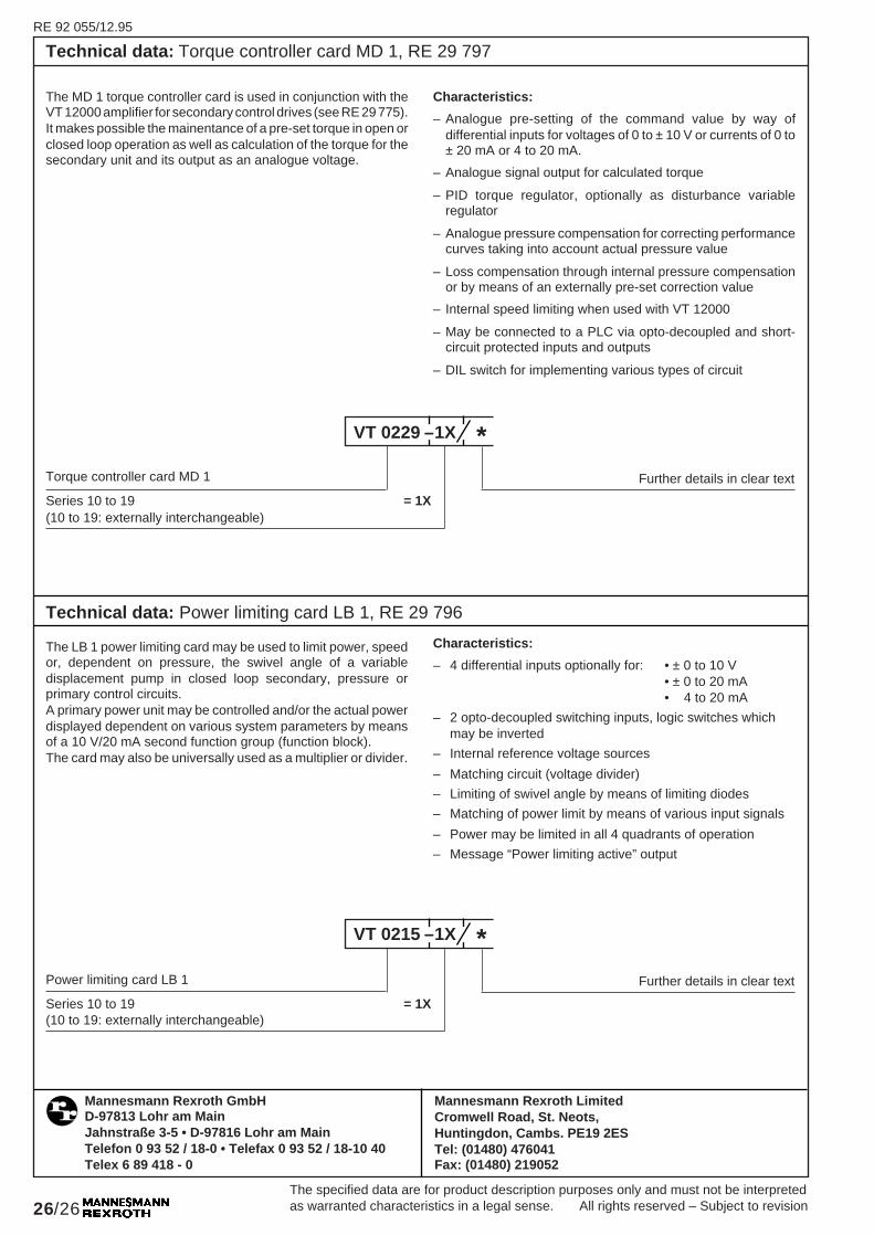
Technical data: Torque controller card MD 1, RE 29 797
The MD 1 torque controller card is used in conjunction with theVT 12000 amplifier for secondary control drives (see RE 29 775).It makes possible the mainentance of a pre-set torque in open orclosed loop operation as well as calculation of the torque for thesecondary unit and its output as an analogue voltage.
Characteristics:
– Analogue pre-setting of the command value by way ofdifferential inputs for voltages of 0 to ± 10 V or currents of 0 to± 20 mA or 4 to 20 mA.
– Analogue signal output for calculated torque
– PID torque regulator, optionally as disturbance variableregulator
– Analogue pressure compensation for correcting performancecurves taking into account actual pressure value
– Loss compensation through internal pressure compensationor by means of an externally pre-set correction value
– Internal speed limiting when used with VT 12000
– May be connected to a PLC via opto-decoupled and short-circuit protected inputs and outputs
– DIL switch for implementing various types of circuit
Torque controller card MD 1
Series 10 to 19 = 1X(10 to 19: externally interchangeable)
*
Further details in clear textPower limiting card LB 1
Series 10 to 19 = 1X(10 to 19: externally interchangeable)
*
Technical data: Power limiting card LB 1, RE 29 796
The LB 1 power limiting card may be used to limit power, speedor, dependent on pressure, the swivel angle of a variabledisplacement pump in closed loop secondary, pressure orprimary control circuits.A primary power unit may be controlled and/or the actual powerdisplayed dependent on various system parameters by meansof a 10 V/20 mA second function group (function block).The card may also be universally used as a multiplier or divider.
Characteristics:
– 4 differential inputs optionally for: • ± 0 to 10 V• ± 0 to 20 mA• 4 to 20 mA
– 2 opto-decoupled switching inputs, logic switches whichmay be inverted
– Internal reference voltage sources
– Matching circuit (voltage divider)
– Limiting of swivel angle by means of limiting diodes
– Matching of power limit by means of various input signals
– Power may be limited in all 4 quadrants of operation
– Message “Power limiting active” output
VT 0229 –1X
VT 0215 –1X