control of dusting in bctmp drying - theseus
TRANSCRIPT

TAMPERE POLYTECHNIC Paper Technology FINAL THESIS Janne Nieminen Control of dusting in BCTMP drying Thesis Supervisor Pertti Viilo (MSc) Commissioning Company M-real Tako Board. Lielahti BCTMP Mill Supervisor: Petri Vuorijärvi (MSc) Tampere 2005

TAMPERE POLYTECHNIC
Paper Technology
Janne Nieminen Control of dusting in BCTMP drying
Final Thesis 27 pages
Thesis Supervisor Pertti Viilo (MSc)
Commissioning Company M-real Tako Board. Lielahti BCTMP Mill
Supervisor: Petri Vuorijärvi (MSc)
October 2005
Keywords BCTMP, pulp drying, dusting, retention aid
ABSTRACT
Changes in the pulping process in the Lielahti BCTMP mill have
lead to dusting problem in the dryer section. Excessive amount of
dust inside the dryer decreases the drying capacity.
The aim of this thesis is to study the factors that cause the dusting
problem and how to reduce or eliminate it. One part of the study is
to follow the effect of retention aid addition on dusting on dryer
section.
Based on the measurements and other findings the retention aid
chemical has no effect on dusting in the dryer section. Although,
improved drainage enables to increase basis weight of dried pulp
which reduces calculated amount of dust per produced pulp ton.
There is a lot of work to be done to decrease dusting in the dryer
section. Based on this study the problem cannot be solved by
making modifications in pulp drying machine. The source of this
problem occurs earlier in the process.

Janne Nieminen FINAL THESIS 3(27)
TABLE OF CONTENTS ABSTRACT..........................................................................................................................2 1. Introduction...................................................................................................................4 2. CTMP process in Lielahti Mill .......................................................................................4 3. Background information ...................................................................................................5
3.1. Lielahti BCTMP mill ...............................................................................................6 3.2. Switch from SGW raw material to BCTMP in Tako Board .....................................6 3.3. Changes in Lielahti BCTMP mill pulp production...................................................6
3.3.1. Lower refining rate..........................................................................................7 3.3.2. Higher refining intensity..................................................................................8 3.3.3. The new plate design .....................................................................................9
4. Lielahti BCTMP mill pulp drying machine ...................................................................11 4.1. General................................................................................................................11 4.2. Wire section.........................................................................................................11 4.3. Press section.......................................................................................................11 4.4. Dryer section .......................................................................................................11
4.4.1. Pulp drying with airborne web ......................................................................11 4.4.2. Internal air circulation system.......................................................................12 4.4.3. The nozzle design ........................................................................................13 4.4.4. Maintenance and service .............................................................................14 4.4.5. Cleaning .......................................................................................................14
5. Consequences of excessive dusting in dryer section .................................................15 6. Retention aid research................................................................................................17
6.1. Retention aid .......................................................................................................17 6.2. Preliminary laboratory research...........................................................................17
6.2.1. Laboratory tests............................................................................................17 6.2.2. Laboratory results.........................................................................................18
7. Measurements and results .........................................................................................22 7.1. Introduction..........................................................................................................22 7.2. Fiber length distribution .......................................................................................22 7.3. Monitoring dusting inside the dryer......................................................................23
8. Conclusion..................................................................................................................24 8.1. Increase of basis weight ......................................................................................24
REFERENCES ..................................................................................................................26

Janne Nieminen FINAL THESIS 4(27)
1. Introduction
The purpose of this thesis was to study the dusting problem in
Lielahti BCTMP mill drying section. Excessive amounts of dust
inside the dryer cause drying capacity decrease. The aim was to
search the solution to reduce or eliminate this problem.
The second chapter introduces briefly BCTMP process on a
general level. The third chapter of this work clarifies the
background of this problem from a theoretical point of view. The
main emphasis is on the issues that changes in production
process have caused. The fourth chapter is the description of
Lielahti BCTMP mill pulp drying machine concentrating on the
dryer section in which the actual problem appears. Chapter five
sums up the consequences of the excessive dusting problem.
The experimental part is based on retention aid research and the
measurements on dryer section which were performed in Lielahti
BCTMP mill pulp drying machine at the same time with retention
aid research made by Eka Chemicals AB. The last chapter
presents the conclusions.
2. CTMP process in Lielahti Mill
The chemi-thermo-mechanical process is a modification of the
TMP process. The most significant difference compared to TMP
process is the chemical treatment for chips. The used chemical
for this treatment is sodium sulphite (Na2SO3). The main raw
material of Lielahti mill is spruce chips. Mixture of spruce and
birch chips is also used. Utilization of this 50%/50% spruce/birch
mixture has increased lately. As seen on Figure 1, the chemical
processing is performed before the refining stage. Preheating the
chips together with sodium sulphite softens the wood matrix. In
this way the defiberation process is more gentle and detached

Janne Nieminen FINAL THESIS 5(27)
fibers are in a more intact state than without chemical treatment.
[7]
Figure 1. Diagram of general CTMP process. [7]
Refining is performed in single a stage by two Metso RGP 60
types of single disc refiners. Main refiners are installed parallel
and those can be controlled independently. After washing stage
the pulp is screened. The pressure screening removes shives and
bundles of unrefined pulp to reject treatment. Rejected pulp is
refined in Metso RGP 46/50 type of reject refiner. Peroxide
bleaching can increase the brightness level up to 80% ISO.
Mainly 70% and 80% ISO brightness levels are used. From
bleaching the pulp is thickened and pumped into storage tower.
[7]
3. Background information
M-real closed Lielahti BCTMP mill market pulp production in
summer 2004. So far Lielahti Mill had been producing fluff pulp for
hygiene products. Freeness (CSF) level of fluff pulp for hygiene
products was around 650ml. In July 2004, the integration of Tako
Board mill and Lielahti BCTMP mill was completed. Since then

Janne Nieminen FINAL THESIS 6(27)
Lielahti have focused on the production of BCTMP as raw
material for Tako Board. Tako Board utilizes BCTMP in middle
layer of paper board production. [1]
3.1. Lielahti BCTMP mill
Lielahti BCTMP mill is part of M-real Tampere Tako board mill.
Lielahti mill produces approximately 110,000 t/a Bleached-Chemi-
Thermomechanical pulp as raw-material for paper board
production. Lielahti mill BCTMP is used in middle-layer of paper
board. The pulp is dried in airborne dryer and cut in sheet cutter
to bales in Lielahti mill. The BCTMP bales are delivered from
Lielahti mill to Tako mill in the center of the town by lorry
transport.
3.2. Switch from SGW raw material to BCTMP in Tako Board
Before the integration of Tako board mill and Lielahti BCTMP
Tako used stone ground wood (SGW) from own SGW-plant and
little amounts of BCTMP from Lielahti pulp mill to middle-layer of
folding boxboard. Now the Tako board SGW plant is closed and
BCTMP is the only raw material used for FBB middle layer. The
present quality standards for consumer packages set high
requirements for FBB. Cleanliness is an important factor
especially in foodstuff board. This restricts usage of chemicals in
the production. For this reason any additional chemicals are not
added to Lielahti BCTMP. Advantages of BCTMP in board
products are high stiffness, good dimensional stability, and a low
content of extractives. [5]
3.3. Changes in Lielahti BCTMP mill pulp production
The switch to pulp production for board grades instead of fluff for
board grades caused changes in the production process. Most of

Janne Nieminen FINAL THESIS 7(27)
the changes took place in pulping department. The main wood
raw material is spruce. The new requirements for produced pulp is
average fiber length <1,6mm and freeness value targeted to
470ml (CSF). The way of refining was adjusted to meet new
specifications of end product.
After these changes in production the dust amount in drying
section have been increased significantly. Presumption is that
energy saving defiberation process is harsher for fiber than
conventional method.
3.3.1. Lower refining rate
The refiner output and the used mechanical energy determine the
refining rate. The refining rate is indicated as the specific energy
consumption (SEC) per each ton of air dry pulp (MWh/t). External
fibrillation of the fiber needs high refining energy. Lower specific
energy refining leaves fibers more intact and level of fibrillation is
lower. Therefore the bonding ability of fiber is also decreased.
[5,7]

Janne Nieminen FINAL THESIS 8(27)
Figure 2. High refining intensity together with low SEC produces
more broken fibers. [7]
3.3.2. Higher refining intensity
Refining intensity is defined as the average energy of the impacts
directed to fibers. Higher refining intensity means harsher refining
with a narrow disc clearance. High radial pulp flow in narrow disc
clearance gives short residence time of the fiber in the disc gap. A
short residence time reduces the amount of pulp in the gap.
However, one must notice that there are only a few empirical tests
made concerning the residence time, and the refining intensity is
still a theoretical quantity. Increased refining intensity has a
tendency to reduce the length of the fibers. Therefore, high
intensity refining can be described as a cutting type of refining.

Janne Nieminen FINAL THESIS 9(27)
This type of refining weakens the bonding ability of fibers and
fiber fractions [5,7]
3.3.3. The new plate design
The plate design has the most significant impact in the refining
intensity. Plates of the both main refiners and reject refiner are
now equipped with low energy segments (LETM) which are
developed and manufactured by Metso Paper. Using low energy
segment design on refiner plates makes it possible to save
measurable amounts of energy. A pilot plant scale trials have
shown that it is possible to decrease the refining energy by 20 %
[6, 7]
Figure 3. Conventional refiner segments with radial tooth pattern.
[5]

Janne Nieminen FINAL THESIS 10(27)
In the low energy segment tooth angle deviates from radial
direction compared to a conventional refiner segment. The angle
of teeth forms a pumping effect in the disc gap. The result of this
feature is a faster feed of pulp into the refining zone and a shorter
residence time in refining. In this way the intensity of refining is
increased. Higher intensity effectively refines coarse fibers and
reduces shives especially in the reject refining. This type of
geometry in tooth pattern reduces the turbulence at the inlet
section of the refiner which leads to reduce of specific refining
energy consumption. Low energy segments are also used to
change the fiber length distribution of the pulp. [6]
Figure 4. Basic operating principle of the low energy segments.
[6]

Janne Nieminen FINAL THESIS 11(27)
4. Lielahti BCTMP mill pulp drying machine
4.1. General
The pulp is dried in a drying machine that consists of wire section,
press section, drying section and sheet cutter. Basis weight is
approximately 600 g/m2, line speed 90 m/min and desired dry
content 85%. Trim width at the sheet cutter is 378 cm.
4.2. Wire section
The stock is fed from a rectifier roll head box onto a wire equipped
with a hybrid former, where Fourdrinier section precedes the twin-
wire nip. The wire section is equipped with forming rolls, foils and
four suction boxes for dewatering downwards in Fourdrinier
section and three suction boxes in hybrid former for upward
dewatering. [2]
4.3. Press section
The press section is equipped with a two-nip press and a suction
roll to pick-up web from wire to press section. The dry content of
web after press section is around 50%.
4.4. Dryer section
4.4.1. Pulp drying with airborne web
Airborne pulp drying is a non-contact drying method. The pulp
web never touches any heated steel surfaces. The dryer utilizes
heated air to dry and support the pulp web. The moist web enters
at the top of the dryer. The airborne web then makes 11
horizontal passes back and forth before it leaves the dryer at
approx. 15% moisture. The delay time of the web inside the dryer

Janne Nieminen FINAL THESIS 12(27)
is approximately 5 min when the line speed is 90 m/min. The hot
and dry supply air enters at the bottom of the dryer. It is re-
circulated and reheated several times in the internal circulation
system. [3,8]
Figure 5. Fläkt dryer internal circulation system [3]
The wet web entering the first blow box deck on the top of the
dryer is impinged by air with the highest moisture content. At the
bottom of the dryer, where the web has a high dryness, it is
impinged by air with lower moisture content. This type of drying
results in high capacity and decreased heat consumption. [3]
4.4.2. Internal air circulation system
The circulation air fan, steam coils and blow boxes build up the
internal circulation air system. The dryer consists of 26 identical
vertical sections. To maximize the heat economy, only a small
percentage of circulation air is exhausted. Approx. 95% of the air
is re-circulated in this system. The circulation air is reheated by the
steam coils and impinged through blow boxes with nozzles on both

Janne Nieminen FINAL THESIS 13(27)
sides of the web. As the air circulates upward in the dryer, its
humidity increases. [4, 8]
4.4.3. The nozzle design
The nozzle geometry and configuration are essential for reliable
function and for a high efficiency of the two side blow box system.
The distance between blow boxes and pulp web must also be very
short in order to have a high drying efficiency. The web tension in
the machine direction is low because it is only the air friction for
web transport that has to be overcome. In cross machine direction
the drying takes place under tension free conditions. Flutter free
web transport at a low web tension results in a high runnability. [4]
Figure 6. Fläkt dryer blow box deck with airborne web. [3]

Janne Nieminen FINAL THESIS 14(27)
4.4.4. Maintenance and service
The dryer with airborne web has few moving parts and this
minimises the need for maintenance. All bearings are located
outside the heated part of the dryer. During normal operation, only
circulation air fans and one drive motor is in function. The rolls are
freewheeling and the transmission and threading tape are
stopped.
Platforms at the inlet and outlet ends and inspection doors give full
access to the dryer. Blow boxes are liftable and built in light make
inspection and cleaning of the blow box deck easy [4].
4.4.5. Cleaning
The steam coils are equipped with fine mesh wire screen frame.
The wire screen works as a filter before the circulating air flow
moves through steam coils. To maintain the whole drying capacity
the dryer must be cleaned at regular intervals. The wire screen
frames are cleaned three times a week. This can be done without
machine shutdown during normal production running. The wire
screen frames are cleaned with vacuum cleaner trough inspection
doors from both sides of the dryer. Each work shift cleans one
third of the frames. In all, it takes three shifts to clean all the
screen frames of the whole dryer, which means that all the screen
frames are cleaned during 24 hours.

Janne Nieminen FINAL THESIS 15(27)
Figure 7. The wire screen frames are cleaned with vacuum
cleaner.
The blow boxes can not be cleaned during production running. To
clean the blow boxes the dryer must be stopped and the inside
temperature must cool down to a safe level. Cleaning is performed
with a long suction hose inside the blow box. This cleaning
operation is done 2-3 times per year during planned maintenance
shutdowns. This operation is very time-consuming because each
of the blow boxes must be cleaned separately.
The dryer needs to be checked from inside before tail threading,
because there might be ripped pieces of pulp web inside the dryer
between top and bottom blow boxes after web break.
5. Consequences of excessive dusting in dryer section
An excessive amount of dust forms a very thick layer on wire
screens inside the dryer. This makes the cleaning with a vacuum
cleaner very difficult. When the wire screen is clear the finest

Janne Nieminen FINAL THESIS 16(27)
fraction of dust goes through it with air flow. It takes some time
before the fibrous material in circulated air forms a filtrating mat
on the wire screen surface. When the mat is formed the filtration
level of screen increases. In that case if the cleaning is performed
more often the more fine material goes through the wire screen
filter.
Figure 8. Thick layer of dust on one of the wire screens of dryer.
The finest fraction of dust accumulates inside the blow boxes
starting from the tip of the sealed end. This is a more serious
harm because the blow boxes can not be cleaned during
production running. When the whole diameter of blow box gets full
of dust the air nozzles are blocked-up. This is very problematic,
especially in the bottom blow boxes whose task is to keep the
web airborne with an air flow. The lack of support makes the pulp
web flutter or even get on contact with the blow box. This will
increase the intensity of mechanical stress onto the web surface.
If the web starts to flutter too much horizontally it might cause a
web break.

Janne Nieminen FINAL THESIS 17(27)
6. Retention aid research
6.1. Retention aid
Since early days, retention aids have been commonly used in
papermaking. In pulp drying machines where the mechanical
retention is significantly higher than in paper machine utilization of
retention aid is very rare.
In the beginning of 2005 Eka Chemicals was interested to try the
effect of retention aid chemical on retention and drainage in
Lielahti BCTMP mill pulp drying machine. Especially better
drainage on wire section was a desired feature, because this
makes the drying process more efficient. Surely, improved
retention also develops the process towards a better direction. In
addition to this, it was assumed that a slightly improved dry
strength can lead to decrease of dusting on drying section.
However, according to Eka Chemicals any guarantees of this kind
effect with this retention aid can not be given.
6.2. Preliminary laboratory research
In February 2005 Eka Chemicals did laboratory research with two
different retention aid polymers in Lielahti BCTMP mill laboratory.
The tested polymers were Eka PL 1510U and Eka PL 2610U.
Both of them are cationic charged polyalcrylamides. The effect on
retention was tested with both polymers alone and also in
conjunction with two different Eka NP colloidal silica sols.
6.2.1. Laboratory tests
Effect of retention aid on Lielahti BCTMP mill stock was tested by
Eka Chemicals sales engineers Seppänen Hanna and Haulivuori
Sami. The Dynamic Drainage Jar (DDJ), also called The Britt Jar,

Janne Nieminen FINAL THESIS 18(27)
permits direct measurement of first-pass retention of solids under
turbulent conditions independent of mat formation. [9]
Figure 9. The Dynamic Drainage Jar. [9]
6.2.2. Laboratory results
The effects of five different dosage levels 25, 50, 75, 100 and 125
g/t on retention were tested. As the graph of Figure 10 shows the
DDJ-retention is doubled with fairly low dosage of polymers
compared to situation were no chemicals are used as retention
aid. It is possible to reach very high level of retention with dosage
from 50 to 75 g/t. However, these results are not directly
proportional on mill scale wire retention values. [10]

Janne Nieminen FINAL THESIS 19(27)
30
40
50
60
70
80
90
100
0 25 50 75 100 125
polymeeriannos g/t
retentio %
PL 1510U
PL 2610U
Figure 10. DDJ-retention for different dosage levels of PL 1510U
and PL 2610U polymers. [10]
The conjunctions with Eka NP colloidal silica sols were also
tested. Increase on the level of retention was not noticeable from
the level that was achieved with polymers. It is more beneficial to
use only polymers to improve retention.
70
75
80
85
90
95
50 75 100 125
NP-annos g/t
retentio %
PL 1510U+ NP442
PL 1510U + NP 900PL 2610U+ NP442
PL 2610U + NP 900
Figure 11. DDJ-retention for colloidal silica conjunctions with
polymers. [10]

Janne Nieminen FINAL THESIS 20(27)
6.3. Mill scale trial run
The decision to perform a mill scale trial run on drying machine
was made because of good results. The chosen polymer for the
trial run was Eka PL 2610 U without colloidal silica sol. This
alternative was easier to carry out. Addition of polymer in stock
was possible to do without any major alteration in process or
process equipments. [12]
Eka PL 2610 U is supplied in 1050kg containers in form of
emulsion where the active content is 43 – 46 %. Before adding
into stock the polymer emulsion must be diluted. This can be
done with automatic dissolver that prepares the solution. [12]
Figure 12. Polymer dissolver equipment.
After dissolving the solution is transferred to a feeding tank. From
this tank solution is drawn off with positive displacement pump.
The solution is diluted 10 times before the feeding point, in order
to ensure good distribution throughout the stock. Typical addition

Janne Nieminen FINAL THESIS 21(27)
point would be in the thin stock between the fan pump and
machine screen. In Lielahti drying machine there is no machine
screen after fan pump, so the addition point is before the fan
pump. Fan pump provides necessary distribution for polymer
throughout the stock. [12]
Normal dosage for retention and drainage improvements will
range from 500 to 2500 g/t in paper machines. In this case, for
pulp drying machine dosage level can be lower. Three different
dosage levels were tested. Based on the laboratory results the
chosen dosages were 30, 125 and 250 g/t. The presumed optimal
dosage is from 100 to 125 g/t. The lower and higher dosages
were tested to get clearly noticeable retention level difference on
measurements. [11]
91
92
93
94
95
96
97
98
0 50 100 150 200 250 300
Polymer dosage (g/t)
Rete
ntio
n (%
)
Figure 13. Retention increase with polymer dosage. [11]
Retention increased significantly as seen on Figure 13. Lower
energy consumption of suction pumps in wire section indicates
that drainage was improved as well. Also the lower use of heating
energy in dryer section was observed.
Janne Nieminen FINAL THESIS 22(27)
7. Measurements and results
7.1. Introduction
Measurements of this work were concentrated mainly on the
dusting phenomenon in the drying section. Monitoring of dusting
level inside the dryer was executed before and during the polymer
addition in the stock.
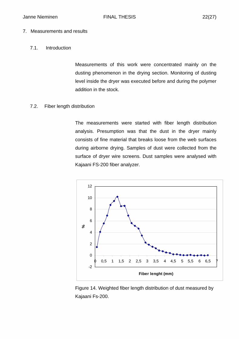
7.2. Fiber length distribution
The measurements were started with fiber length distribution
analysis. Presumption was that the dust in the dryer mainly
consists of fine material that breaks loose from the web surfaces
during airborne drying. Samples of dust were collected from the
surface of dryer wire screens. Dust samples were analysed with
Kajaani FS-200 fiber analyzer.
-2
0
2
4
6
8
10
12
0 0,5 1 1,5 2 2,5 3 3,5 4 4,5 5 5,5 6 6,5 7
Fiber lenght (mm)
%
Figure 14. Weighted fiber length distribution of dust measured by
Kajaani Fs-200.

Janne Nieminen FINAL THESIS 23(27)
The analysis proved that presumption of high fine material content
was wrong. Actually, the fiber length distribution of dust is
practically identical with fiber length distribution of the produced
pulp. Average fiber length is 1,54 mm when the target fiber length
is <1,6 mm.
7.3. Monitoring dusting inside the dryer
The selection of method and device to determine the level of
dusting in the dryer was problematic. Steamy and hot conditions
set limitations for measurements. The absolute amount of dust
inside the dryer is impossible to measure when machine is
running. The decision was to select fixed measuring point from
inside the dryer. The chosen method was to observe the amount
of dust that filtrates on the specific area of one wire screen of
dryer in certain period of time. This way it is possible to observe
the variation of dusting during production running. Specified area
was two wire screens of the dryer. Height of the screen is 370 cm
and width 100 cm. Total observed area was in that case 7,4 m2.
Specified period of time for dust filtration measurements was 4
hours.
The industrial vacuum cleaner turned out to be the most reliable
device for collecting the filtrated dust from the surface of wire
screen to container of vacuum cleaner. The container was
equipped with a detachable dust bag. The weight of the collected
dust was rather simple to weigh when the weight of empty dust
bag was known.
Janne Nieminen FINAL THESIS 24(27)
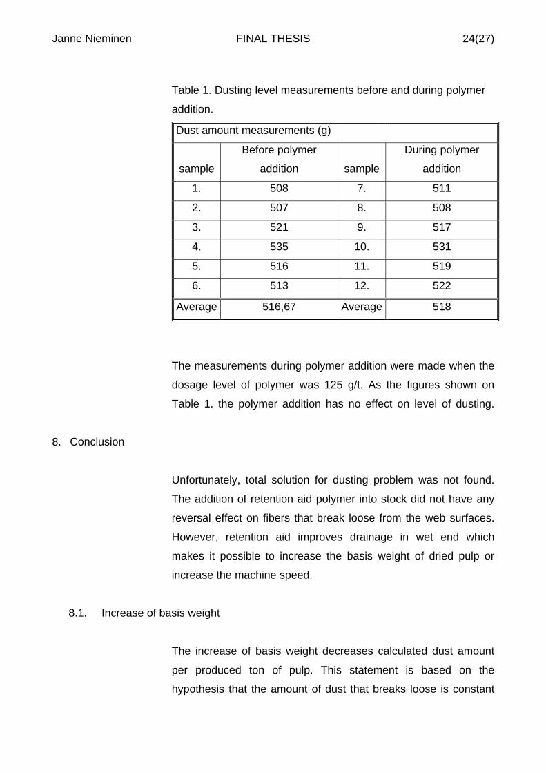
Table 1. Dusting level measurements before and during polymer
addition.
Dust amount measurements (g)
sample
Before polymer
addition sample
During polymer
addition
1. 508 7. 511
2. 507 8. 508
3. 521 9. 517
4. 535 10. 531
5. 516 11. 519
6. 513 12. 522
Average 516,67 Average 518
The measurements during polymer addition were made when the
dosage level of polymer was 125 g/t. As the figures shown on
Table 1. the polymer addition has no effect on level of dusting.
8. Conclusion
Unfortunately, total solution for dusting problem was not found.
The addition of retention aid polymer into stock did not have any
reversal effect on fibers that break loose from the web surfaces.
However, retention aid improves drainage in wet end which
makes it possible to increase the basis weight of dried pulp or
increase the machine speed.
8.1. Increase of basis weight
The increase of basis weight decreases calculated dust amount
per produced ton of pulp. This statement is based on the
hypothesis that the amount of dust that breaks loose is constant

Janne Nieminen FINAL THESIS 25(27)
compared to certain area of web surface. So, if the basis weight is
increased from 600 g/m2 to 700 g/m2 this means that
approximately 16,7 % more pulp can be pass trough the dryer
with same web surface area.
If the volume of production is held in the same level it is possible
to run the drying machine with a slower line speed. This can
decrease the mechanical stress on the web surface.

Janne Nieminen FINAL THESIS 26(27)
REFERENCES
[1] M-real year 2004: Annual review
[2] PAULAPURO, HANNU (ed.). Papermaking science and
technology: Book 8 Papermaking Part 1, Stock Preparation and
Wet. Papermaking chemistry Helsinki: Fapet Oy 1998.
[3] VTT INDUSTRIAL SYSTEMS. KnowPulp 2.4 (CD-rom).
Espoo. Last modified 27.05.2003.
[4] GULLICHSEN, JOHAN (ed.). Papermaking science and
technology: Book 6 Chemical Pulping. Papermaking Chemistry
Helsinki: Fapet Oy 1998.
[5] SUNDHOLM, JAN (ed.) Papermaking science and technology:
Book 5 Mechanical Pulping. Papermaking Chemistry Helsinki:
Fapet Oy 1998.
[6] VUORIO, P; BERGQUIST, P. “New refiner segments
technology to optimize fiber quality and energy consumption of
refiner mechanical pulp.” 2005 African Pulp and Paper week
conference. TAPPSA Archive. (cited 14.5.2005) Available in
World Wide Web: http://tappsa.co.za/archive/
[7] VTT INDUSTRIAL SYSTEMS. KnowPap 5.0 (CD-rom). Espoo.
Last modified 28.05.2003.
[8] FLÄKT Oy. Fläkt Compact Dryer. sales brochure. 1989

Janne Nieminen FINAL THESIS 27(27)
[9] NEIMO, LEO (ed.) Paper making science and technology:
Book 4 Papermaking Chemistry. Papermaking Chemistry
Helsinki: Fapet Oy 1998.
[10] HAULIVUORI, S; SEPPÄNEN, H. Lielahti BCTMP retention
aid laboratory research report. Eka Chemicals AB. Tampere.
22.2.2005.
[11] SEPPÄNEN, H. Lielahti BCTMP retetion and drainage
measurements. Eka Chemicals AB. Tampere. May 2005.
[12] EKA CHEMICALS. Eka Facts: Eka PL 2610 U. Data sheet.
Rev. date 1.10.2004.